
Effect of design parameters in nanocatalyst synthesis on pyrolysis for producing diesel-like fuel from waste lubricating oil†
Riny Yolandha
Parapat
 *a,
Aji Tri
Laksono
a,
Rizki Imam
Fauzi
a,
Yuni
Maulani
a,
Freddy
Haryanto
b,
Alfian
Noviyanto
c,
Michael
Schwarze
d and
Reinhard
Schomäcker
d
*a,
Aji Tri
Laksono
a,
Rizki Imam
Fauzi
a,
Yuni
Maulani
a,
Freddy
Haryanto
b,
Alfian
Noviyanto
c,
Michael
Schwarze
d and
Reinhard
Schomäcker
d
aChemical Engineering Department, Institut Teknologi Nasional Bandung, PHH, Mustopha 23, 40124 Bandung, Indonesia. E-mail: rinyyolandha@itenas.ac.id
bPhysics Department, Institut Teknologi Bandung, Ganesha 10, 40132, Bandung, Indonesia
cDepartment of Mechanical Engineering, Mercu Buana University, Jl. Meruya Selatan, Kebun Jeruk, Jakarta 11650, Indonesia
dDepartment of Chemistry, Technische Universität Berlin, Straße des 17, Juni 124, 10623 Berlin, Germany
First published on 5th August 2024
Abstract
Converting waste lubricating oil into diesel-like liquid fuels using pyrolysis presents a dual solution, addressing environmental pollution while offering a viable response to the fossil energy crisis. However, achieving high-quality fuel with a substantial yield necessitates the utilization of highly active and cost-effective catalysts. We report the development of Fe–Ni nanocatalysts, synthesized using a green approach and supported on TiO2, as a promising strategy for converting waste lubricating oil into premium-grade diesel-like fuel. To ensure efficient and effective pyrolysis processes, tailoring the synthesis parameters of these nanocatalysts is indispensable. In this study, we investigate the effect of design parameters on nanocatalyst synthesis, such as the concentrations of pre-catalysts and reducing agents, reducing time, and the amount of support material, and evaluate their impact on the quality and quantity of pyrolysis products. Through optimization of the synthesis process, a high quality diesel-like fuel with a product yield of about 54% at a mild reaction temperature of 400 °C was obtained. This study highlights the critical role of nanocatalysis in addressing persistent environmental and energy challenges while showcasing the potential of green nanocatalysts in sustainable waste-to-energy conversion processes.
1. Introduction
In recent years, the interest in sustainable energy sources has intensified due to escalating environmental concerns and the need to reduce reliance on finite fossil fuels.1–3 As a result, researchers have turned their attention towards exploring innovative approaches for converting waste materials into valuable energy resources. One such waste stream with significant potential for energy recovery is waste lubricating oil, generated from various automotive operations.4–6 Improper disposal of this waste poses serious environmental risks, including soil and water contamination, air pollution, and adverse health effects.7–9 Addressing these challenges requires the development of an effective process for converting waste lubricating oil into useful energy products. Among various methods, thermal and catalytic processes are the most promising ones for producing fuel oil.10 One particularly effective method is catalytic pyrolysis, which operates at elevated temperatures, typically between 400 °C and 800 °C, in the absence of oxygen. The addition of a catalyst lowers the activation energy required for the pyrolysis reactions, thereby enhancing conversion efficiency and selectivity towards desired products. This approach is especially effective at converting biomass, plastic waste, and other organic materials into valuable renewable energy sources and chemicals.11–14 It can mitigate environmental pollution by reducing the volume of waste and providing an alternative pathway to conventional fossil fuels.15–17 However, the efficiency and yield of pyrolysis processes depend heavily on the choice and performance of catalysts.Zeolites, alumina and silica–alumina are commonly used as catalysts in pyrolysis. The microporous structure of zeolites provides a high surface area and acid sites that facilitate cracking reactions, although they may have lower activity. Alumina and silica–alumina are cost-effective options but can have lower activity and selectivity compared to other catalysts.18 Among the various nanocatalysts explored for pyrolysis applications, bimetallic Fe–Ni nanocatalysts can be a promising option as they may offer high activity and selectivity for targeted products in pyrolysis.19 This is due to their very small particle size, which provides a very large surface area, and the bimetallic properties that enhance reaction synergy and catalytic activity.20 Fe active sites play a crucial role in forming low-chain olefins and transform them into aromatic hydrocarbons. Fe also adsorbs carbonaceous intermediates and catalyzes hydrogen transfer reactions.21 Ni catalysts are effective at hydrogenating and removing oxygen-containing functional groups such as carbonyl, carboxyl, and hydroxyl (deoxygenating) from feedstocks, resulting in a cleaner and more stable product.22 With their ability to facilitate hydrocarbon cracking and reforming, these catalysts are well-suited for promoting the conversion of complex hydrocarbons found in waste lubricants.23,24 Therefore, the synergistic effects arising from the combination of Fe and Ni can further enhance catalytic performance, leading to improved product selectivity and yield. Supported Fe–Ni nanocatalysts combine metal activity with the stability and good dispersion of the support, which can improve pyrolysis performance. However, they require careful control of synthesis and operation to avoid deactivation. Ongoing research and optimization are necessary to fully harness their potential and address any remaining challenges in their application. In terms of oil yield, supported Fe–Ni nanocatalysts produce higher yields compared to other types of catalysts.
Nanocatalysts, particularly those synthesized using environmentally friendly methods, hold immense potential in enhancing the efficiency and selectivity of pyrolysis reactions. The efficient conversion of waste lubricants into high-quality diesel-like fuels via pyrolysis hinges on the meticulous design and selection of nanocatalysts.25,26 Nanocatalysts play a pivotal role in enhancing the kinetics and selectivity of pyrolysis reactions, thereby influencing the yield and quality of the resulting fuels. In this context, the choice of catalyst composition and support material is of significant importance.27 Using nanocatalysts in the pyrolysis of waste lubricating oil offers several environmental benefits compared to traditional methods. Nanocatalysts enhance process efficiency, significantly reducing the amount of residual waste, which minimizes overall waste generation. Additionally, they can produce higher quality products such as fuels with better combustion properties, leading to lower emissions. Nanocatalysts also operate effectively at lower temperatures, resulting in lower energy consumption and a reduced carbon footprint. Furthermore, nanocatalysts can be engineered to target and neutralize specific contaminants in waste lubricating oil, leading to cleaner products and minimizing the release of toxic substances into the environment. These advantages make nanocatalysts a promising alternative to traditional methods, contributing to more sustainable and environmentally friendly waste management practices.
Various nanocatalysts have been investigated for pyrolysis applications; however, the development and design of Fe–Ni bimetallic nanocatalysts have yet to be explored. As mentioned above, this combination holds significant promise due to the synergistic effects between iron (Fe) and nickel (Ni), potentially leading to a catalyst with enhanced activity and selectivity towards desired products.19 Supported Fe–Ni nanocatalysts combine metal activity with the stability and good dispersion of the support, which can improve pyrolysis performance. Ongoing research and optimization are necessary to fully harness their potential and address any remaining challenges in their application. In terms of oil yield, supported Fe–Ni nanocatalysts produce higher yields compared to other types of catalysts. Selecting titanium dioxide (TiO2) as a support material for Fe–Ni nanocatalysts can be advantageous due to its distinctive physicochemical properties. TiO2 offers high thermal stability, excellent dispersion characteristics, and compatibility with metal nanoparticles,28 thereby providing a robust support for anchoring and stabilizing Fe–Ni particles.
In the pyrolysis process, irrespective of the chosen methodology, it is vital to fine-tune the factors that have a significant influence on attaining the targeted yield and product quality. In a recent study employing microwave-assisted pyrolysis for converting plastic waste into energy, alterations in feedstock type, particle size, and reactor temperatures were found to elevate yield rates, while optimizing reactor temperature concurrently mitigated the emission of harmful gaseous by-products.29
In this study, we developed highly efficient Fe–Ni/TiO2 nanocatalysts by tuning the synthesis parameters to enhance the transformation of waste lubricants into diesel-like fuels through mild pyrolysis. Specifically, the Fe–Ni nanocatalysts were synthesized using environmentally friendly (green synthesis) methods, with the goal of maximizing their effectiveness and efficiency in the pyrolysis process. Green synthesis methods contribute significantly to the sustainability of nanocatalyst production by using renewable, non-toxic materials, improving energy efficiency, minimizing waste and emissions, ensuring safer working conditions, and enhancing overall resource efficiency. These methods align with the principles of green chemistry and sustainable development, promoting environmentally friendly practices and reducing the ecological footprint of nanocatalyst production. This sustainable approach is not only beneficial for the environment but also supports the long-term viability and acceptance of nanocatalysts in various industrial applications, including waste lubricating oil pyrolysis.
By elucidating the effect and intricate interplay between the significant factors, this study aims to advance our understanding of nanocatalysis in the pyrolysis process and provide insights into the development of tailored catalyst systems for sustainable waste-to-energy conversion. Through systematic experimentation, characterization, and evaluation, the performance of Fe–Ni/TiO2 nanocatalysts can be maximized. We demonstrate the feasibility of producing premium diesel-like fuels with high yields using tailored nanocatalysts and pave the way for their practical implementation in industrial-scale pyrolysis reactors.
Driven by the rapidly growing need to address environmental problems, energy security, and waste management,30 we developed green nanocatalysts to increase efficiency and convert waste into fuel. The novelty of this research is the design of a Fe–Ni nanocatalyst supported on TiO2 with an environmentally friendly synthesis process for producing a high quality fuel from waste lubricating oil. This research presents a new approach for the high-yield conversion of waste lubricating oil into diesel-like fuel with superior quality, offering a sustainable and efficient route for waste valorization. This nanocatalyst aims to achieve efficient catalytic pyrolysis for converting waste lubricating oil into high-quality diesel-like fuel at moderate temperatures (400 °C). Utilizing these green nanocatalysts in pyrolysis reactors can significantly improve the catalytic process. This study contributes to the field of nanocatalysis for waste-to-energy conversion and addresses the goals of the circular economy.
2. Materials and methods
2.1 Materials
The synthesis of Fe–Ni/TiO2 nanocatalysts was achieved using a direct method, the precipitation synthesis approach. Nickel chloride hexahydrate (NiCl2·6H2O, 99.9%, Sigma-Aldrich) and iron chloride hexahydrate (FeCl2·6H2O, 99.9%, Sigma-Aldrich) were used as metal precursors, dissolved in deionized water. The reducing solution was prepared by dissolving mangosteen peel (Mastin®, Indonesia) in 100 ml of deionized water, followed by an extraction process involving stirring the mixture at 700 rpm and 70 °C for an hour. Subsequently, solid components were efficiently removed through centrifugation. CristalActiv-TiO2 (PC-105, Tronox) served as the support material for the nanocatalyst. Cleaning of the attached Fe–Ni nanocatalyst on the TiO2 surface was carried out using acetone (99.9%, Carl-Roth).2.2 Designing the highly active Fe–Ni/TiO2 nanocatalyst for an efficient pyrolysis process
As mentioned above, our goal is to design a catalyst that can produce high oil yield with premium quality. The general step in designing the nanocatalyst in this work is presented in Fig. 1. We designed the process to operate at room temperature, utilizing affordable and safe materials, thereby making it environmentally friendly and economically viable.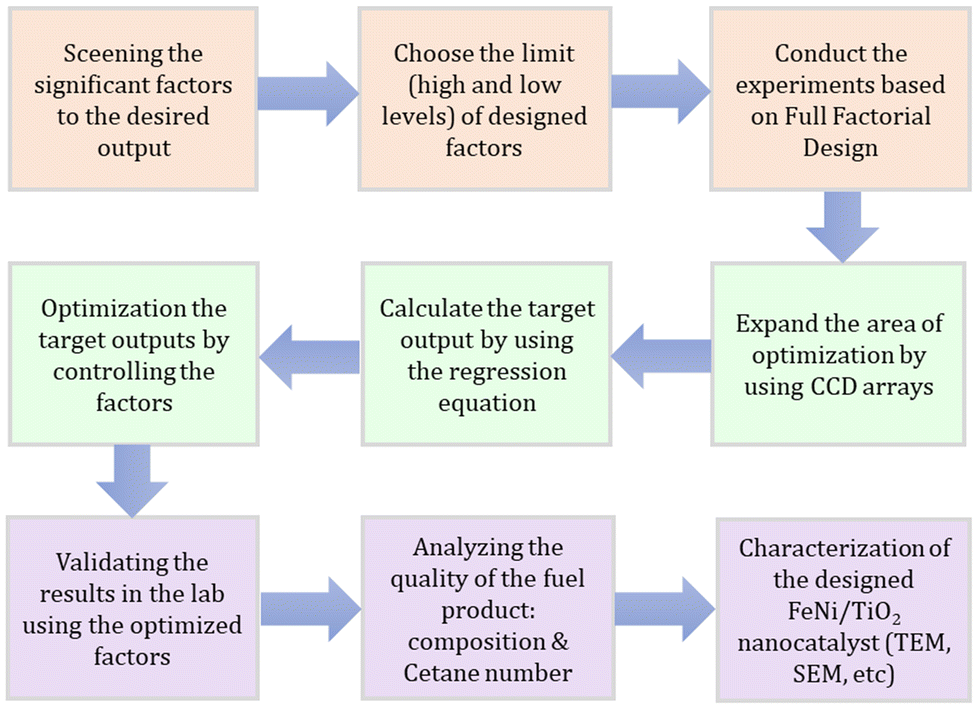 | ||
| Fig. 1 The general step to design the Fe–Ni/TiO2 nanocatalyst in this work. | ||
The screening of the significant factors in the nanocatalyst synthesis that can affect the activity of the catalyst synthesis has been done in our previous work. We found that the concentrations of the metal precursors and the reducing agent, the synthesis time, and the amount of the catalyst support20,31–33 are the four most significant factors. The concept of designing green nanocatalyst Fe–Ni/TiO2 in this work is shown in Fig. 2.
 | ||
| Fig. 2 The concept of designing the Fe–Ni/TiO2 nanocatalyst in this work. | ||
The first approach is conducting the experiments based on Full Factorial Design (FFD) according to a number of factors. The choice of the high and low levels is based on the prediction. Afterward, we expand the number of experiments using Central Composite Design (CCD). We calculate the outputs based on the regression equation from FFD and use those values for simultaneous optimization using Response Surface Methodology (RSM). The results were validated in the lab experiments using the optimized factors. The quality of the product from the experiment was analysed to determine the hydrocarbon composition, calorific value, cetane number, viscosity and density of the liquid fuel. The final step is to characterize the nanocatalyst and elucidate the nanocatalysis in the pyrolysis process.
![[thin space (1/6-em)]](https://www.rsc.org/images/entities/char_2009.gif) :3) into the reactor. Next, a micro pump added 25 ml of the reducing solution, which included mangosteen peel extract (MPE), to the reactor at a controlled flow rate of 0.2 ml s−1. The temperature was then set to 25 °C after activating the thermostat. With a stirrer operating at 700 rpm, the synthesis process was initiated. The growth of Fe–Ni nanoparticles takes place during the synthesis time. After the specified duration, a TiO2 support was introduced into the reactor, initiating a 2-hour deposition process. Subsequently, the resulting Fe–Ni nanoparticles, now deposited onto the TiO2 support, were meticulously separated using a centrifuge, followed by thorough washing with pure acetone. The catalyst then underwent calcination at 300 °C for 2 hours.
:3) into the reactor. Next, a micro pump added 25 ml of the reducing solution, which included mangosteen peel extract (MPE), to the reactor at a controlled flow rate of 0.2 ml s−1. The temperature was then set to 25 °C after activating the thermostat. With a stirrer operating at 700 rpm, the synthesis process was initiated. The growth of Fe–Ni nanoparticles takes place during the synthesis time. After the specified duration, a TiO2 support was introduced into the reactor, initiating a 2-hour deposition process. Subsequently, the resulting Fe–Ni nanoparticles, now deposited onto the TiO2 support, were meticulously separated using a centrifuge, followed by thorough washing with pure acetone. The catalyst then underwent calcination at 300 °C for 2 hours.
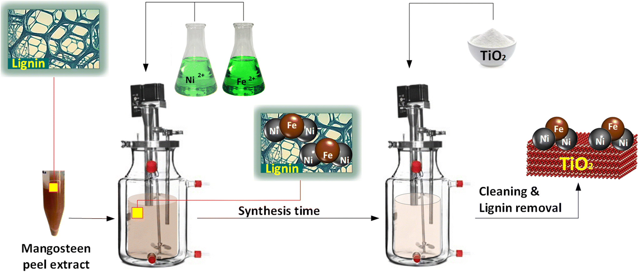 | ||
| Fig. 3 Schematic of nanocatalyst synthesis. | ||
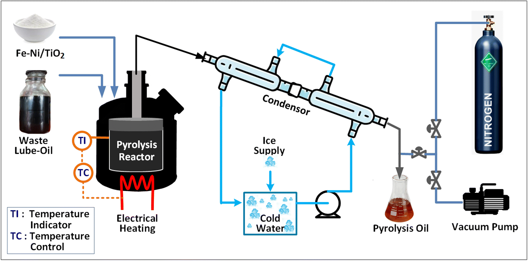 | ||
| Fig. 4 Schematic of the pyrolysis process. | ||
3. Results and discussion
3.1 Full Factorial Design (FFD) with four responses
Initial experiments were conducted based on FFD. Four factors (parameters) were varied in order to get high fuel yield by evaluating three responses as shown in Table 1. Fig. 5 illustrates the visual characteristics of the obtained pyrolysis oil based on FFD, which appears transparent and brownish. This suggests that a significant portion of the long-chain hydrocarbons, typically black or dark in color, have undergone cracking into shorter-chain hydrocarbons.34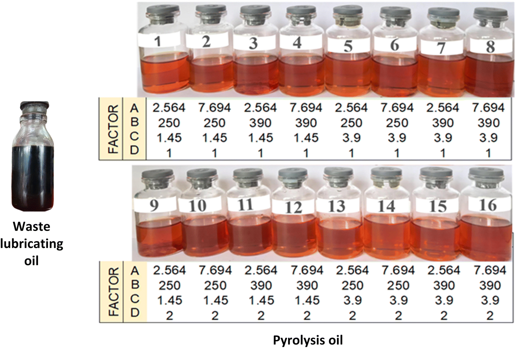 | ||
| Fig. 5 The product of mild pyrolysis of waste lubricating oil based on FFD. | ||
| Run | Factor | Response | ||||||
|---|---|---|---|---|---|---|---|---|
| (A) | (B) | (C) | (D) | Calorific value (cal g−1) | Oil yield (%) | Density (kg m−3) | Catalyst yield (%) | |
| 1 | 7.694 | 390 | 3.9 | 1 | 10844 |
48.50 | 793 | 65.14 |
| 2 | 7.694 | 250 | 3.9 | 1 | 10915 |
38.91 | 798 | 63.92 |
| 3 | 7.694 | 250 | 1.45 | 2 | 10956 |
45.31 | 781 | 69.89 |
| 4 | 5.129 | 320 | 2.675 | 1.5 | 10883 |
43.34 | 791 | 63.67 |
| 5 | 7.694 | 390 | 1.45 | 1 | 10739 |
45.30 | 784 | 62.61 |
| 6 | 2.564 | 390 | 1.45 | 2 | 11045 |
42.90 | 797 | 59.09 |
| 7 | 5.129 | 453 | 2.675 | 1.5 | 10796 |
45.06 | 792 | 65.03 |
| 8 | 7.694 | 390 | 3.9 | 2 | 10939 |
44.80 | 793 | 68.92 |
| 9 | 7.694 | 250 | 3.9 | 2 | 10991 |
42.92 | 791 | 68.69 |
| 10 | 5.129 | 320 | 2.675 | 2.45 | 11029 |
41.96 | 790 | 62.59 |
| 11 | 5.129 | 320 | 2.675 | 0.55 | 10736 |
44.72 | 793 | 64.76 |
| 12 | 5.129 | 320 | 2.675 | 1.5 | 10883 |
43.34 | 791 | 63.67 |
| 13 | 2.564 | 390 | 3.9 | 2 | 10974 |
39.48 | 790 | 59.47 |
| 14 | 2.564 | 390 | 1.45 | 1 | 10280 |
41.21 | 790 | 80.61 |
| 15 | 2.564 | 390 | 3.9 | 1 | 10954 |
46.99 | 796 | 56.31 |
| 16 | 5.129 | 320 | 2.675 | 1.5 | 10883 |
43.34 | 791 | 63.67 |
| 17 | 5.129 | 320 | 2.675 | 1.5 | 10883 |
43.34 | 791 | 63.67 |
| 18 | 5.129 | 187 | 2.675 | 1.5 | 10970 |
41.62 | 790 | 62.32 |
| 19 | 2.564 | 250 | 1.45 | 2 | 10899 |
41.83 | 791 | 62.07 |
| 20 | 5.129 | 320 | 0.347 | 1.5 | 10773 |
42.90 | 789 | 63.66 |
| 21 | 7.694 | 250 | 1.45 | 1 | 10872 |
39.44 | 792 | 49.87 |
| 22 | 2.564 | 250 | 3.9 | 1 | 10952 |
48.03 | 785 | 73.26 |
| 23 | 5.129 | 320 | 2.675 | 1.5 | 10883 |
43.34 | 791 | 63.67 |
| 24 | 5.129 | 320 | 2.675 | 1.5 | 10883 |
43.34 | 791 | 63.67 |
| 25 | 7.694 | 390 | 1.45 | 2 | 10920 |
44.76 | 789 | 62.95 |
| 26 | 2.564 | 250 | 1.45 | 1 | 10889 |
44.12 | 797 | 62.23 |
| 27 | 2.564 | 250 | 3.9 | 2 | 10953 |
38.90 | 790 | 53.75 |
| 28 | 5.129 | 320 | 5.002 | 1.5 | 10992 |
43.77 | 793 | 63.69 |
| 29 | 5.129 | 320 | 2.675 | 1.5 | 10883 |
43.34 | 791 | 63.67 |
| 30 | 0.255 | 320 | 2.675 | 1.5 | 10855 |
42.57 | 793 | 63.06 |
| 31 | 10.002 | 320 | 2.675 | 1.5 | 1090 | 44.11 | 789 | 64.29 |
In this study, we elaborate the findings to provide a deeper understanding of the underlying mechanisms governing the pyrolysis process and underscore the significance of the catalyst's composition and design in achieving sustainable and efficient conversion of waste lubricants into high-quality liquid fuel. The simulation process was carried out using the Central Composite Design (CCD) method, and 31 data points were used in this process.
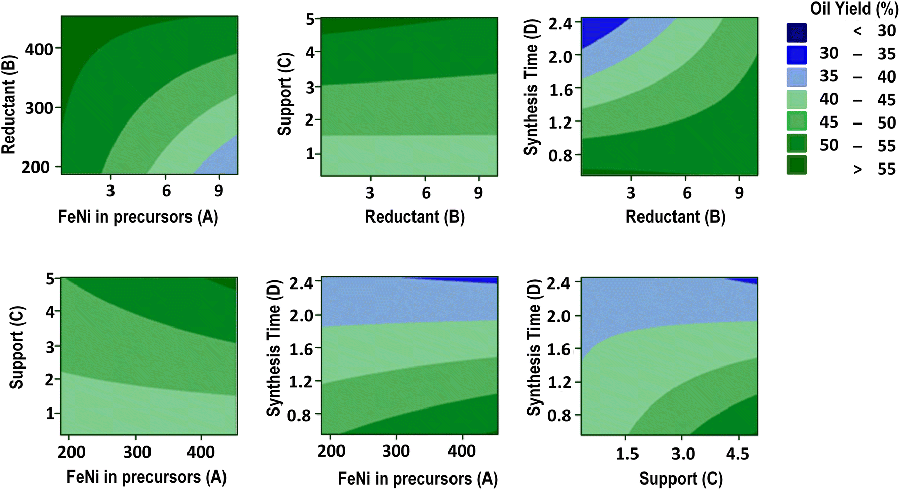
To maximize the oil yield, it is important to thoroughly analyse the intricate interactions among the factors. As illustrated in Fig. 6A, the interaction between factor A (the amount of metals in the precursors) and factor B (the amount of reductant) is particularly noteworthy. This interaction reveals that the impact of factor A on oil yield greatly depends on the value of factor B. Specifically, at higher values of B, an increase in A leads to a notable enhancement in the oil yield. However, at lower values of B, the correlation is reversed. This phenomenon underlines the critical role of ensuring sufficient green reductant to effectively reduce metal ions, thereby facilitating the full production of nanoparticles, which serve as catalysts.35,36 Neglecting this issue could lead to a less than optimal oil yield. Due to the comparatively lower reductive capabilities of natural reducing agents, it is essential to ensure their sufficient quantity to enable the formation of stable anisotropic structures,31,33 thereby maximizing the availability of active sites.
 | ||
| Fig. 6 Factor interaction plots for the response of the oil yield. The impact of the FeNi in precursor varying MPE (A), amount of support (B), and time (C), along with the effect of MPE varying amount of support (D) and time (E), and the impact of support varying time (F). | ||
The polyphenols, including lignin compounds, in MPE serve both as reducing agents and stabilizing agents, preventing aggregation and ensuring the stability of the nanoparticles prior to their attachment to the TiO2 support. Polyphenols possess many hydroxyl groups (–OH) that can donate electrons. During the reduction process, these hydroxyl groups are oxidized to carbonyl groups (C![[double bond, length as m-dash]](https://www.rsc.org/images/entities/char_e001.gif) O), effectively losing electrons. The electrons released from the oxidation of polyphenols are transferred to the metal ions (Mn+), reducing them to their metallic state (M0). This reduction transforms metal ions into metal atoms. The metal atoms start to aggregate, forming small clusters or nuclei. The nuclei grow by further reduction of metal ions and deposition of metal atoms onto the existing nuclei. This process continues until the nanoparticles reach a stable size. Polyphenols stabilize nanoparticles and prevent them from aggregating excessively by adsorbing onto the surface of the nanoparticles, providing steric stabilization.37 The protective layer also passivates the nanoparticle surface, preventing oxidation or further reaction with the environment.
O), effectively losing electrons. The electrons released from the oxidation of polyphenols are transferred to the metal ions (Mn+), reducing them to their metallic state (M0). This reduction transforms metal ions into metal atoms. The metal atoms start to aggregate, forming small clusters or nuclei. The nuclei grow by further reduction of metal ions and deposition of metal atoms onto the existing nuclei. This process continues until the nanoparticles reach a stable size. Polyphenols stabilize nanoparticles and prevent them from aggregating excessively by adsorbing onto the surface of the nanoparticles, providing steric stabilization.37 The protective layer also passivates the nanoparticle surface, preventing oxidation or further reaction with the environment.
The influence of MPE on oil yield does not seem to be very significant as can be seen in Fig. 6D and E. Because MPE acts as a weak reductant, increasing its amount in the synthesis of nanocatalysts does not significantly influence the shape and size of the resulting nanocatalysts. In terms of surface chemistry, specifically the interactions occurring on the catalyst's surface that influence the rate and course of the chemical reactions, MPE does not appear to significantly affect the conversion and oil yield. In the synthesis process, MPE absorbed on the catalyst surface was removed through cleaning with pure acetone and a subsequent calcination process. During pyrolysis, any remaining MPE compounds on the catalyst's surface will be completely burned; therefore, the catalyst's surface can still provide active sites, where hydrocarbon molecules in the feedstock can be more easily absorbed and react.
The correlation between factor A (the quantity of Fe and Ni in the precursor) and factor C (the support amount) appears consistently proportional, as evidenced in Fig. 6B. This observation suggests that achieving a high oil yield necessitates an increase in the metal content within the precursor, alongside ensuring adequate support to facilitate nanoparticle attachment without agglomeration. Similarly, a comparable trend is observed between factors A and D, as illustrated in Fig. 6C. Irrespective of the synthesis time variation, enhanced metal content in the precursor invariably results in an elevated oil yield. However, it is noteworthy that enhancing the metal quantity in the precursor extends the duration required for the production of stable nanoparticles.38
The interactions between the quantity of MPE (factor B) and either the amount of support (factor C) or synthesis time (factor D) exhibit similar trends, as shown in Fig. 6D and E. The influence of the MPE reductant on the oil yield appears to be relatively modest across various support amounts and synthesis times. In the scenario illustrated in Fig. 6D, where a low quantity of metal precursor was utilized at a short synthesis time, resulting in the production of a limited number of nanoparticles, increasing the support amount only slightly impacts oil yield, possibly due to improved dispersions. Conversely, in the scenario presented in Fig. 6E, it is evident that extending the synthesis time after the stable nanoparticle formation stage does not significantly affect the oil yield. This suggests that in both instances portrayed in Fig. 6D and E, all metal ions were likely fully reduced by the MPE within the given timeframe, resulting in the production of stable nanoparticles.
An intriguing scenario unfolds in Fig. 6F, where an increase in the support amount is observed to enhance the oil yield. However, a shifted trend emerges as the synthesis time lengthens, whereby the oil yield exhibits a slight decline. Elevating the support quantity promotes optimal nanoparticle dispersion, thereby enhancing the catalytic activity. Yet, prolonged synthesis durations may trigger nanoparticle agglomeration on lignin particles, which undergo movement during mixing. Consequently, this aggregation reduces nanocatalyst efficacy, subsequently decreasing the oil yield.
In this study we also elucidate the factors affecting the calorific value and density of the pyrolysis oil from waste used lubricating oil. The significant factors affecting the calorific value (Fig. S1 in the ESI†) of the pyrolysis products were found to be the amount of reductant, TiO2, the synthesis time, and the interaction between the amount of reductant and the synthesis time, as well as the interaction between TiO2 and the synthesis time. The significant factors affecting the oil density (Fig. S2†) were found to be the interaction between the amount of reductant and the synthesis time, and the interaction between TiO2 and the amount of metal. Therefore, to get the desired oil density and calorific value, the combination of all those interactions needs to be considered.
Additionally, not only the pyrolysis product was evaluated; it was also noteworthy to evaluate the effectiveness of the nanocatalyst synthesis. The significant factors affecting the catalyst yield (the quantity of Fe–Ni that successfully attaches to the support, as analyzed using ICP-MS) were AC and AD (Fig. S3†). The interaction between the metal amount (A) and the synthesis time (C) and the interaction between the metal amount (A) and the support amount (D) have significant positive effects on the catalyst yield. This suggests that the quantity of Fe–Ni and TiO2 enhances the formation of the nanocatalyst, resulting in a higher catalyst yield. Increasing the reaction time also had a positive effect on the catalyst yield, as it allows complete formation of the catalyst.
These findings have important implications for the development of more efficient catalysts for pyrolysis processes. To get the optimum results, i.e. the maximum oil yield with premium quality, the factors in nanocatalyst synthesis need to be optimized. In this study, we use the Response Surface Methodology (RSM) to optimize the results by means of Minitab® software. For data evaluation, we manually set the factors according to the interaction analysis between the factors as mentioned above and finding the location in the contour plots.
Fig. 7 shows contour plots of the oil yield, which illustrate the complex interaction between the metal amount (A), the reductant amount (B), the support amount (C), and the synthesis time (D) on the pyrolysis outcomes. The contour plots of calorific value are available in the ESI (Fig. S4†), along with the density (Fig. S5†) and the catalyst yield (Fig. S6†). The contour plots visualize the relationships between these factors and can be instrumental in the optimization process. The analysis revealed the optimal conditions for achieving a high oil yield (>50%), i.e. the metal amount (A) should not exceed 3.5 mg and the reductant amount (B) should exceed 400 mg, TiO2 support (C) should be at least 5 g, and the synthesis time (D) should remain below 0.55 h. This condition is also seen in the surface plot presented in Fig. 8.
 | ||
| Fig. 7 Contour plot of the oil yield in the pyrolysis process. | ||
 | ||
| Fig. 8 Surface plots of the oil yields that resulted from the interaction between the metal amount and the reductant amount (A) and from the interaction between the support amount and the synthesis time (B). | ||
To attain the target calorific value of the pyrolysis oil (10770 cal g−1), specific conditions must be met: the Fe–Ni metal composition (A) should not exceed 3 mg, the quantity of the reducing agent (B) should surpass 400 mg, the supporting TiO2 (C) should exceed 4 g, and the synthesis time (D) should not exceed 1 h. Similarly, to achieve the desired density (870 kg m−3), the optimal parameters include a metal precursor (A) below 3 mg, a reductant (B) above 400 mg, a TiO2 support (C) of over 4.5 g, and a synthesis time (D) not exceeding 1 h. Furthermore, to obtain a catalyst yield exceeding 60%, it is necessary to maintain a metal precursor amount (A) below 3 mg, a reductant quantity (B) exceeding 400 mg, a TiO2 support (C) exceeding 4.5 g, and a synthesis time (D) not exceeding 1 h. Consequently, these identified optimal conditions require further investigation and comprehensive evaluation to ascertain their efficacy in optimizing the pyrolysis process.
The results of nanocatalyst optimization using Minitab® software for a high-performing pyrolysis process are presented in Fig. S9.† Theoretically, employing 2.564 mg of Fe–Ni metal salt, 453 mg of reducing agent, 5.0 g of TiO2 support, and a reaction time of 0.55 hours can maximize the nanocatalyst yield to 67.12%. This condition is also seen in the overlapping contour plots in Fig. 9. Consequently, this optimized catalyst is predicted to increase the pyrolysis oil yield, calorific value, and density to 55.66%, 1086 cal g−1, and 788 kg m−3, respectively. To experimentally verify these theoretical findings, we conducted trials using the identified optimal values. These validation efforts demonstrate close agreement with the predicted values, with slight errors of 2.77%, 3.62%, and 0.16% observed for oil yield, calorific value, and density, respectively (Table 2). The oil quality produced by the optimized results was further examined using GC/MS analysis. We reviewed relevant references and subsequently tested our product, as presented in Fig. 10 and Table 3.
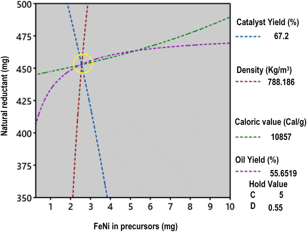 | ||
| Fig. 9 Overlapping contour plots of oil yield. Calorific value and nanocatalyst yield, which result in the optimization point. | ||
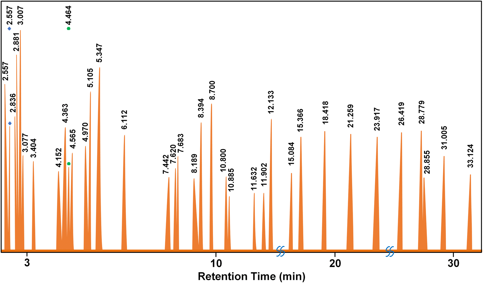 | ||
| Fig. 10 Graphical analysis of pyrolysis oil with GC-MS. | ||
| Parameter | Average | Minitab optimization | Validation | Error (%) |
|---|---|---|---|---|
| Oil yield (%) | 43.35 | 55.65 | 54.11 | 2.77 |
| Caloric value (cal g−1) | 10882 |
10860 |
10957 |
3.62 |
| Density (kg m−3) | 791 | 788 | 799 | 0.16 |
| Peak | Retention | Compound name | Formula | wt% | CN | CNa (wt%) |
|---|---|---|---|---|---|---|
| a Ref. 39. | ||||||
| 1 | 2.557 | 2,4-Dimethyl hexane | C8H18 | 3.59 | 63 | 2.26 |
| 2 | 2.663 | 3-Methyl hexane | C7H16 | 2.07 | 56 | 1.16 |
| 3 | 2.836 | 2-Methyl-1-hexene | C7H14 | 2.40 | 25 | 0.60 |
| 4 | 2.881 | Cycloheptane | C7H14 | 3.62 | 40 | 1.45 |
| 5 | 3.007 | n-Heptane | C7H14 | 5.08 | 56 | 2.84 |
| 6 | 3.077 | 2,4-Dimethyl-1,3-pentadiene | C7H12 | 1.96 | 16 | 0.31 |
| 7 | 3.404 | Methyl cyclohexane | C6H11CH3 | 1.49 | 35 | 0.52 |
| 8 | 4.152 | 2-Ethyl-1-butanol | C6H14O | 1.12 | 42 | 0.47 |
| 9 | 4.363 | 2-Methyl heptane | C8H18 | 5.87 | 52.6 | 3.09 |
| 10 | 4.464 | Benzeneacetic acid, 1,1-dimethylethyl ester | C12H16O2 | 2.25 | 50 | 1.13 |
| 11 | 4.565 | 3-Methylheptane | C8H18 | 3.00 | 58 | 1.74 |
| 12 | 4.970 | 2-Methyl-1-heptene | C8H18 | 2.48 | 52.6 | 1.30 |
| 13 | 5.105 | 1-Octene | C8H16 | 3.91 | 29 | 1.13 |
| 14 | 5.374 | n-Octane | C8H18 | 6.14 | 64.4 | 3.96 |
| 15 | 6.112 | Hexamethyl cyclotrisiloxane | C6H18O3Si3 | 4.22 | 58 | 2.45 |
| 16 | 7.442 | 2,6-Dimethyl heptane | C9H20 | 2.49 | 52 | 1.30 |
| 17 | 7.620 | p-Xylene | C6H4(CH3)2 | 2.76 | 30 | 0.83 |
| 18 | 7.683 | 3-Methyl octane | C9H20 | 1.44 | 53 | 0.76 |
| 19 | 8.189 | 2-Methyl-1-octene | C9H18 | 1.29 | 29 | 0.37 |
| 20 | 8.394 | 1-Nonene | C9H18 | 2.93 | 33 | 0.97 |
| 21 | 8.700 | n-Nonane | C9H20 | 5.12 | 60.9 | 3.12 |
| 22 | 10.800 | 2-Ethylhexyl trichloroacetate | C6H9Cl3O3 | 1.59 | 25 | 0.40 |
| 23 | 10.885 | 2-Methylnonane | C10H22 | 1.20 | 56 | 0.67 |
| 24 | 11.632 | 2-Methyl-1-nonene | C10H20 | 1.17 | 34 | 0.40 |
| 25 | 11.837 | 1-Decene | C10H20 | 2.37 | 35 | 0.83 |
| 26 | 11.902 | Mesitylene | C9H12 | 1.28 | 21 | 0.27 |
| 27 | 12.133 | Decane | C10H22 | 3.11 | 66 | 2.06 |
| 28 | 15.084 | 1-Undecene | C11H22 | 1.55 | 37 | 0.57 |
| 29 | 15.366 | Undecane | C11H24 | 2.96 | 66 | 1.95 |
| 30 | 18.418 | Dodecane | C12H26 | 3.51 | 73 | 2.56 |
| 31 | 21.259 | Tridecane | C13H28 | 2.67 | 88 | 2.35 |
| 32 | 23.917 | Tetradecane | C14H30 | 2.90 | 95 | 2.75 |
| 33 | 26.419 | Pentadecane | C15H32 | 3.13 | 98 | 3.07 |
| 34 | 28.779 | Hexadecane | C16H34 | 2.91 | 100 | 2.91 |
| 35 | 28.855 | Diethyl phthalate | C12H14O4 | 1.17 | 10 | 0.12 |
| 36 | 31.005 | Heptadecane | C17H36 | 2.01 | 105 | 2.11 |
| 37 | 33.124 | Nonadecane | C19H40 | 1.24 | 110 | 1.36 |
| Total | 56.13 | |||||
GC-MS analysis of the liquid product obtained from pyrolysis of used lubricating oil using the Fe–Ni/TiO2 catalyst revealed the presence of various hydrocarbon constituents. These include alkanes (paraffin), alkenes (olefins), aromatics, and aliphatics. Among the 49 detected elements, alkanes constituted the most significant fraction at 55.10%, followed by alkenes (32.65%), aromatics (6.12%), and aliphatics (6.12%). The estimated cetane number of the pyrolysis oil is 56.13, based on the data in Table 3. This value signifies excellent ignition capability, as a higher cetane number indicates a propensity for rapid and efficient fuel ignition in diesel engines. Consequently, the liquid fuel derived from the pyrolysis process demonstrates the potential for facilitating stable and efficient combustion in diesel engines, a crucial factor for optimal engine performance. The cetane number of the pyrolysis oil obtained from this research shows a higher value than ordinary diesel. Furthermore, the analysis indicated a predominance of hydrocarbons with shorter carbon chains (C5–C11); about 73% of the identified hydrocarbons fall within this range, while those with longer chains (C12–C25) represent about 27%. Notably, no hydrocarbons with carbon chain lengths exceeding C25 were detected in the liquid product. This suggests the effective cracking of the used lubricating oil into smaller hydrocarbon molecules (Table 4). As can be seen from Fig. 11, the hydrocarbon composition before and after pyrolysis shows a drastic reduction in long-chain hydrocarbons to shorter chain hydrocarbons, which are the most abundant components in diesel oil (C7–C17).
 | ||
| Fig. 11 Hydrocarbon composition before and after pyrolysis. | ||
| HC | Oil in the pyrolysis process | Literature | ||
|---|---|---|---|---|
| Beforea (wt%) | After (wt%) | Dieselb (wt%) | Premium dieselc (wt%) | |
| a Ref. 40. b Ref. 41. c Ref. 42. | ||||
| C6 | 0 | 4.22 | 0 | 0.284 |
| C7 | 1.796 | 18.20 | 0.009 | 0.852 |
| C8 | 5.158 | 28.88 | 0.017 | 1.989 |
| C9 | 9.470 | 14.54 | 0.026 | 3.125 |
| C10 | 6.801 | 7.86 | 0.043 | 4.261 |
| C11 | 5.643 | 4.50 | 0.077 | 5.398 |
| C12 | 2.634 | 6.93 | 0.137 | 6.534 |
| C13 | 0.783 | 2.67 | 0.240 | 7.670 |
| C14 | 0.666 | 2.90 | 0.411 | 8.807 |
| C15 | 0.742 | 3.13 | 0.694 | 9.943 |
| C16 | 0.402 | 2.91 | 1.140 | 11.080 |
| C17 | 0 | 2.01 | 1.817 | 12.216 |
| C18 | 0.797 | 0 | 2.819 | 13.352 |
| C19 | 0 | 1.24 | 4.208 | 14.489 |
| C20-C40 | 65.107 | 0 | 48.73 | 88.362 |
In the context of pyrolysis, the nanocatalytic aspect of Fe–Ni/TiO2 systems manifests through multiple mechanisms. First, the presence of Fe and Ni species promotes the activation and cleavage of carbon–carbon bonds in complex hydrocarbons, facilitating the conversion of long-chain hydrocarbons into shorter, more desirable fuel molecules. Secondly, the interaction between Fe–Ni nanoparticles and the TiO2 support enhances catalytic stability and prevents particle agglomeration, thereby prolonging the catalyst's lifespan and ensuring sustained activity throughout the pyrolysis process. Additionally, the inherent redox properties of the Fe–Ni species enable them to participate in catalytic oxidation and reduction reactions, further modulating the product distribution and composition.43,44
The Fe–Ni metal acts as the active component, influencing the catalysis process and selectivity. Higher Fe–Ni content can lead to increased activity, potentially influencing the composition and density of the pyrolysis oil. Conversely, a lower Fe–Ni content may result in reduced activity and altered product distributions. TiO2 support provides a high surface area (90 m2 g−1) for Fe–Ni nanoparticle dispersion, preventing aggregation and enhancing accessibility to reactants. It also influences the surface chemistry, affecting its interaction with the feedstock and conversion processes. Variations in the amount of TiO2 support can alter the dispersion and stability of the Fe–Ni nanoparticles, impacting the overall catalytic performance.45,46 In many cases, catalytic reactions profit from a high surface area support material. As we have reported in our previous work, a higher surface area might lead to smaller and better dispersed nanoparticles during preparation. We prepared platinum supported on TiO2 with different surface areas for photocatalysis. The high surface area TiO2 modification (PC500) led to the best activity in hydrogen prodution.47 Therefore, the interaction between these factors is crucial, as the specific combination of Fe–Ni and TiO2 levels can lead to synergistic effects impacting the overall catalytic behaviour and, consequently, the density of the pyrolysis oil. Understanding and optimizing this interaction is essential for controlling the oil density and tailoring its properties to meet specific requirements.
Synthesis time plays an important role in determining the catalyst morphology, crystallinity, and surface properties.48 Sufficient time allows the formation and growth of active sites. Longer synthesis times may promote well-defined crystalline structures and enhance active species dispersion, improving catalytic performance and yield. Conversely, shorter synthesis times may result in incomplete site formation or impurities, negatively impacting the yield. The interaction between these factors suggests that the catalyst yield is influenced not only by the individual effects of the Fe–Ni content and the synthesis time but also by their combined effects. Therefore, understanding and optimizing this interaction is crucial for controlling the catalyst yield and ensuring efficient resource utilization in the pyrolysis process.
The excellent performance of the Fe–Ni/TiO2 nanocatalyst in this study can be attributed to its structure. The size, shape, and dispersion characteristics of the nanocatalyst are displayed in the HRTEM images presented in Fig. 12. The structure of the Fe–Ni nanoparticles (NPs) is shown in Fig. 12A and B, which are more likely to exhibit a 2D structure. Although we aimed to obtain bimetallic Fe–Ni nanoparticles, the plain lattice distances indicate an FeNiOx structure. This is a preliminary structural analysis, and further characterization will be conducted in the future to validate this structure. The sizes of FeNiOx nanoparticles ranged from 2 to 5 nm. Possibly, the Fe–Ni nanoparticles were oxidized during TEM preparation; however, the size of the Fe–Ni nanoparticles would be of the same order of magnitude or smaller. The irregular shape of the Fe–Ni NPs provides numerous active sites, as evidenced by the presence of defects contributing to the high activity of these nanocatalysts.33,49 The structure of the Fe–Ni/TiO2 nanocatalyst can be seen through Secondary Electron Iimaging (SEI) in Fig. 12C. Because the Fe–Ni NPs are much smaller than TiO2, they cannot be observed clearly but their dispersion on the support can be seen through a dark field image (Fig. 12D).
 | ||
| Fig. 12 HRTEM images of the Fe–Ni NPs with different magnifications (A) and (B); STEM images of FeNi/TiO2 using Secondary Electron Imaging (SEI) for observing the morphology (C), and High-Angle Annular Dark Field (HAADF) (D). The nanocatalysts were analyzed using HRTEM (“TITAN 80-300 Berlin Holography Special”). | ||
The composition of the Fe–Ni NPs is shown in Fig. 13. Utilizing the actual HRTEM image (Fig. 13A), the mapping of Fe (Fig. 13B), Ni (Fig. 13C), and both Fe and Ni atoms (Fig. 13D) was conducted. Observation of Fig. 13D reveals that some Fe and Ni atoms are bound together, while others are not. Fig. 13E provides evidence of the presence of Fe and Ni atoms within the particles, with the Ni composition slightly higher than that of the Fe atoms.
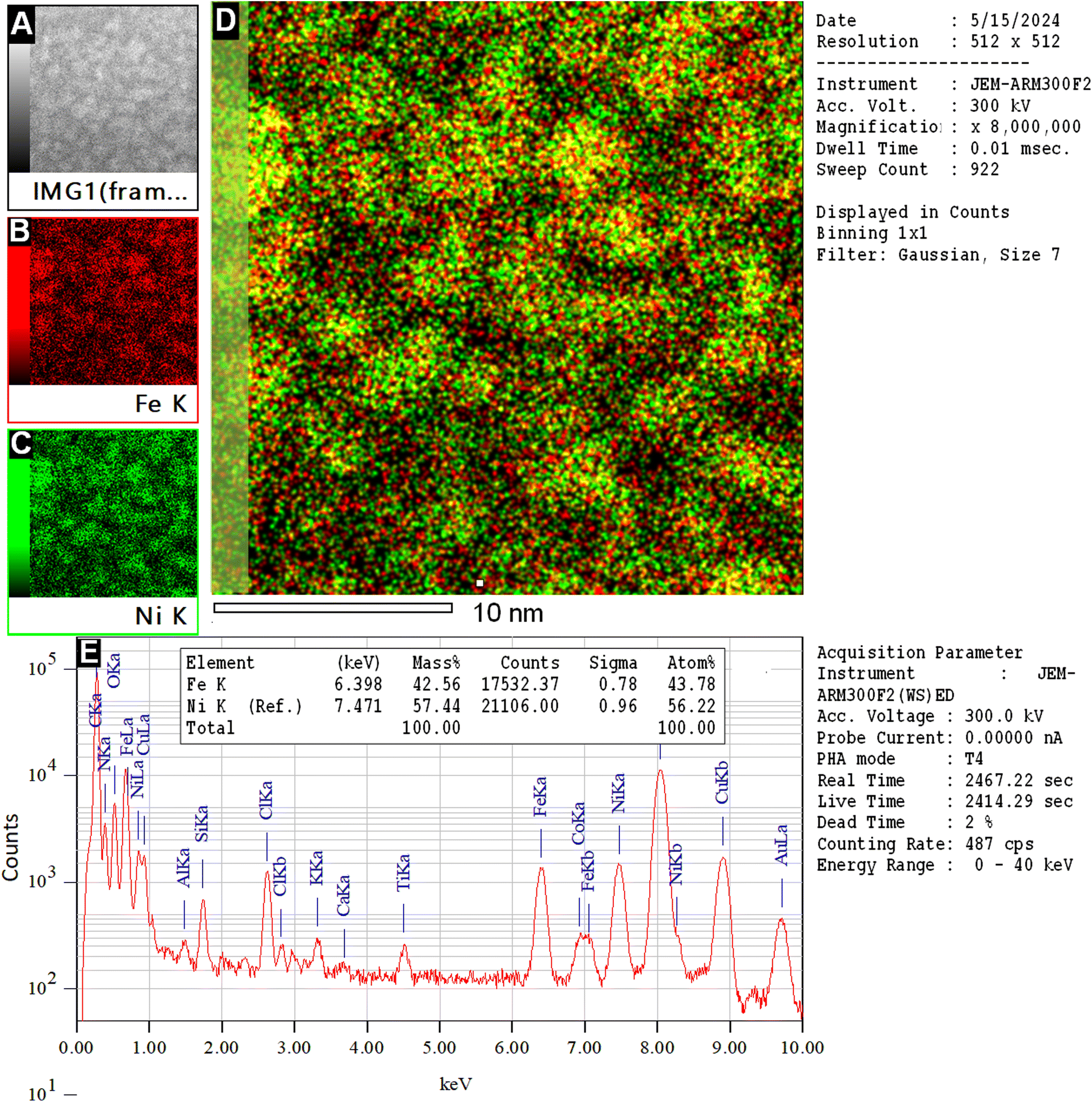 | ||
| Fig. 13 EDX mapping of the Fe–Ni NPs. (A) Initial HAADF image; (B) mapping of Fe; (C) mapping of Ni; (D) overlay of Fe and Ni revealing homogeneously distributed Fe–Ni nanoparticles; (E) EDS analysis of the entire area and quantification. The composition was analyzed using HRSTEM analysis on a probe-corrected JEM-RM300F2 at ZELMI of TU-Berlin. | ||
Fig. 14 presents SEM images of the sample surface at magnifications of 3000× and 40000×. These images reveal that only the size of the TiO2 particles is observable due to the very small size of the Fe–Ni nanoparticles, which is approximately 3.5 nm. The particle size distribution of TiO2, analyzed using PSA, indicates an average size of 881 nm (Fig. S10†). EDS analysis confirms that the surface composition includes Ni and Fe (Fig. 14C).
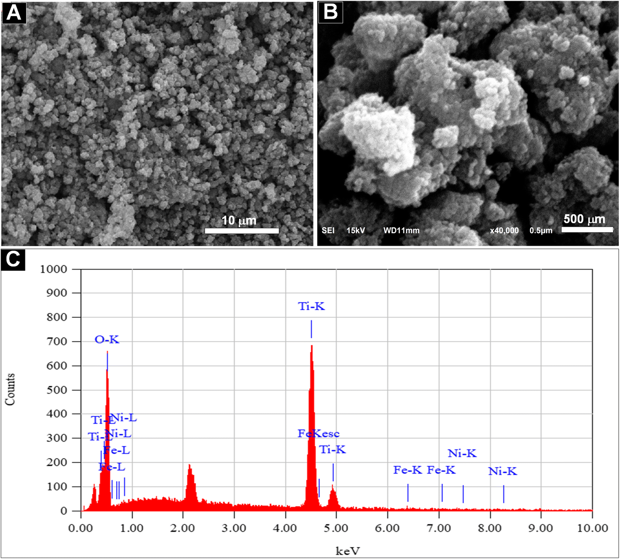 | ||
| Fig. 14 SEM images of the Fe–Ni/TiO2 nanocatalyst at magnifications of 3000× (A) and 40000× (B). The corresponding EDS analysis (C) confirms the presence of Fe–Ni nanoparticles in the catalyst. | ||
XRD analysis of Fe–Ni/TiO2 is shown in Fig. 15. It seems that the peaks of Fe and Ni crystals are hardly detected because they are very small and present in only small amounts in the catalyst. The 2θ = 25.381°, 37.92°, 48.129°, 55.13°, 62.88°, 70.28°, and 75.029° correspond to the (101), (004), (200), (211), (204), (220), and (215) planes of anatase TiO2 (JCPDS card #21-1272), respectively.
 | ||
| Fig. 15 XRD analysis of Fe–Ni/TiO2. | ||
Fig. 16 shows a significant difference in oil yield based on catalyst utilization during the pyrolysis of used lubricating oil. After testing in the same pyrolysis system, the optimized Fe–Ni/TiO2 nanocatalyst produced more oil (54.14%) compared to zeolite (28.09%) and the catalyst-free process. We note here that the catalyst-free process was carried out at a temperature of 650 °C. This notable enhancement of oil yield can be attributed to the better properties of Fe–Ni/TiO2.
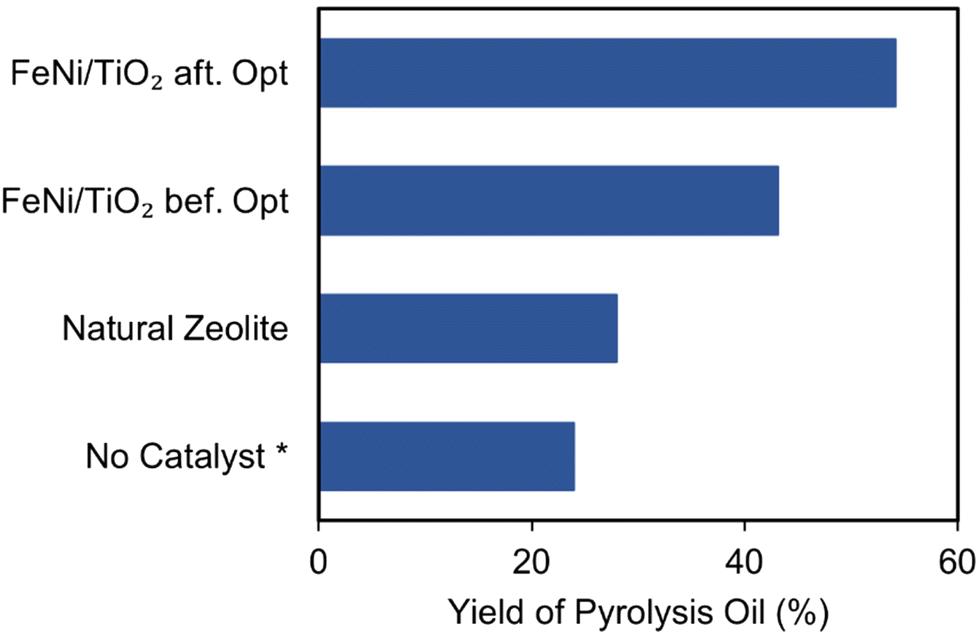 | ||
| Fig. 16 Comparison of oil yields in the pyrolysis of waste lubricating oil using the optimized Fe–Ni/TiO2, natural zeolite, and the catalyst-free process (*the catalyst-free process was carried out at 650 °C). | ||
Blending pyrolysis oil with ordinary diesel oil holds substantial promise for enhancing the quality of diesel fuel. The higher energy content of pyrolysis oil can potentially improve combustion efficiency and engine performance. Additionally, its superior thermal stability can contribute to a more stable blend with a longer lifespan. Beyond technical benefits, utilizing pyrolysis oil serves the dual purpose of waste reduction and resource recovery by adding value to waste materials.
The produced pyrolysis oil typically cannot be used directly and must be blended with other liquid fuels as an additive to enhance the quality of the final fuel product.50 The pyrolysis oil obtained from the catalytic process in this study exhibits higher heating values, lower density, and lower viscosity compared to ordinary diesel oil. Notably, incorporating 50% pyrolysis oil into ordinary diesel oil has the potential to enhance its specifications to resemble those of premium diesel fuel (DEX), as shown in Table 5.
| Quality | Pyrolysis oil (PO) | Ord. diesel (OD) | Mixture of PO:OD = 1:1 |
Premium diesel-DEX |
|---|---|---|---|---|
| Caloric value (cal g−1) | 10957 |
10546 |
10751 |
10755 |
| Density (kg m−3) | 799 | 844 | 821.5 | 840 |
| Viscosity (cSt) | 0.65 | 3.25 | 1.95 | 2 |
| Cetane number | 56.13 | 48 | 50.23 | 50 |
From the results obtained, it can be said that the high oil yield and good quality are due to the effective catalysis process resulting from well-designed nanocatalysts. The anisotropic structure provides plenty of active sites for crucial catalytic reactions. Furthermore, the use of TiO2 as a support material offers several advantages. First, the high surface area of TiO2 facilitates the dispersion of the active Fe–Ni nanoparticles, thereby maximizing their catalytic activity. Secondly, TiO2 exhibits exceptional thermal stability,51,52 allowing it to withstand the harsh conditions of the pyrolysis process. It is suggested that the support structure prevents the agglomeration and sintering of Fe–Ni nanoparticles, ensuring sustained catalytic activity during extended reaction times. The Fe–Ni/TiO2 nanocatalyst effectively facilitates the breakdown of complex hydrocarbons present in used lubricating oil, leading to the increased production of valuable products such as diesel-like oil.
The economic feasibility of implementing these nanocatalysts in commercial pyrolysis plants for fuel production appears promising. Nanocatalysts enhance the efficiency of the pyrolysis process, leading to higher yields of oil with better quality. This increased efficiency can result in lower per-unit production costs. Improved catalytic activity can lower the energy requirements of the pyrolysis process, translating into significant energy cost savings. Furthermore, nanocatalysts often have longer lifespans and higher resistance to deactivation, reducing the frequency and cost of catalyst replacement.
Scaling up the synthesis of nanocatalysts from lab scale to industrial applications involves several technical, economic, and logistical challenges. However, with careful planning and optimization, it is feasible. A thorough economic analysis, including a cost–benefit assessment and payback period calculation, is essential to make a well-informed decision. If the initial investment is justified by the long-term savings and increased revenue, the implementation can be highly beneficial and profitable.
The results of this research contribute to a broader understanding of the catalytic processes in converting waste oil into valuable fuels. This study reveals how synthesis parameters in catalyst preparation indirectly influence the catalytic processes during pyrolysis. Certain synthesis parameters and their interactions are sensitive to product quality and quantity, while others are not. Additionally, this study highlights the importance of developing appropriate, environmentally friendly, and economical strategies for synthesizing active catalysts to achieve an efficient and effective catalytic pyrolysis process for converting waste oil into valuable fuel.
4. Conclusion
The Fe–Ni/TiO2 nanocatalysts, designed using a green synthesis method, demonstrated remarkable catalytic activity in converting waste lubricating oil into high-quality diesel-like fuel. A comprehensive investigation was carried out to elucidate the impact of various factors during nanocatalyst preparation on both the yield and quality of the resulting pyrolysis oil. Interaction plots revealed that the most significant factors influencing oil yield were the interaction between metal concentration and the reductant concentration. Synthesis time, on the other hand, primarily affected the calorific value, while the interaction between metal concentration and the amount of TiO2 support influenced the density of the pyrolysis oil.By optimization and validation, the oil yield was successfully increased to about 54%. The optimized pyrolysis oil also achieved a calorific value of 10957 cal g−1 and a density of 789 kg m−3. Furthermore, GC analysis revealed a composition remarkably similar to that of diesel fuel, which was further supported by a high cetane number of about 52. These characteristics suggest the potential of this oil as a valuable additive to improve the quality of conventional diesel fuel. The results of this study underline the importance of nanocatalyst design for recovering energy from waste lubricating oil through the use of more efficient and environmentally friendly technologies.
Conflicts of interest
The authors declare no conflicts of interest.Acknowledgements
The authors are grateful to the Ministry of Technology Research and Higher Education (Ristekdikti) of Indonesia for the financial support (contract numbers: 106/E5/PG.02.00.PL/2024, 084/SP2H/RT-MONO/LL4/2024, and 327/B.005/LPPM/ITENAS/VI/2024). Special thanks to Sören Selve (Zelmi TU-Berlin) for assisting with the HRTEM analysis, Muhammad Nadhif Noer Hamdhan for preparing the HRTEM samples, and Christoph Fahrenson (Zelmi TU-Berlin) for his help with the SEM analysis.References
- M. J. Albert, Altern. Global Local Polit., 2021, 46, 89–98 CrossRef.
- A. K. Singh, P. Pal, S. S. Rathore, U. K. Sahoo, P. K. Sarangi, P. Prus and P. Dziekański, Energies, 2023, 16, 5409 CrossRef CAS.
- J. O. Unuofin, S. A. Iwarere and M. O. Daramola, Environ. Sci. Pollut. Res., 2023, 30, 90547–90573 CrossRef PubMed.
- F. Chiara and M. Canova, Proc. Inst. Mech. Eng., Part D, 2013, 227, 914–936 CrossRef.
- M. I. Jahirul, F. M. Hossain, M. G. Rasul and A. A. Chowdhury, Energies, 2021, 14, 3837 CrossRef CAS.
- L. Lombardi, E. Carnevale and A. Corti, Waste Manage., 2015, 37, 26–44 CrossRef PubMed.
- I. Ahmad, M. Rehan, M. Balkhyour, M. Abbas, J. Basahi, T. Almeelbi and I. M. Ismail, Int. J. Agric. Environ. Res., 2016, 2, 1–23 Search PubMed.
- F. Ahmed and A. N. M. Fakhruddin, Int. J. Environ. Sci. Nat. Resour., 2018, 11, 1–7 Search PubMed.
- S. Dash, Int. J. Recent Sci. Res., 2015, 6, 2554–2560 Search PubMed.
- M. Sekar, V. K. Ponnusamy, A. Pugazhendhi, S. Nižetić and T. R. Praveenkumar, J. Environ. Manage., 2022, 302, 114046 CrossRef CAS PubMed.
- P. Sambandam, P. Murugesan, V. K. Thangaraj, M. Vadivel, M. Rajaraman and G. Subbiah, Pet. Sci. Technol., 2023, 41, 1113–1130 CrossRef CAS.
- V. L. Mangesh, S. Padmanabhan, P. Tamizhdurai and A. Ramesh, J. Cleaner Prod., 2020, 246, 119066 CrossRef CAS.
- V. L. Mangesh, T. Perumal, S. Subramanian and S. Padmanabhan, Energy Fuels, 2020, 34, 8824–8836 CrossRef CAS.
- P. Sambandam, H. Venu and B. K. Narayanaperumal, Energy Sources, Part A, 2020, 1–17 Search PubMed.
- K. W. Chew, S. R. Chia, W. Y. Chia, W. Y. Cheah, H. S. H. Munawaroh and W.-J. Ong, Environ. Pollut., 2021, 278, 116836 CrossRef CAS PubMed.
- L. Liu, S. Y. Cheng, J. B. Li and Y. F. Huang, Energy Sources, Part A, 2007, 29, 1069–1080 CrossRef CAS.
- A. Pacheco-Lopez, F. Lechtenberg, A. Somoza-Tornos, M. Graells and A. Espuna, Front. Energy Res., 2021, 9, 676233 CrossRef.
- N. Miskolczi, N. Borsodi, F. Buyong, A. Angyal and P. T. Williams, Fuel Process. Technol., 2011, 92, 925–932 CrossRef CAS.
- R. Y. Parapat, Y. Maulani, G. N. Fatimah, F. Haryanto, M. Tasbihi, M. Schwarze and R. Schomäcker, E3S Web of Conferences, EDP Sciences, 2024, vol. 484, p. 03004 Search PubMed.
- R. Y. Parapat, M. F. R. Putra, Z. Zamaludin, D. A. Permadi, I. Aschuri, Y. Yuono, A. Noviyanto, M. Schwarze and R. Schomäcker, J. Kim. Sains Apl., 2023, 26, 391–403 CrossRef CAS.
- P. Li, H. Pan, K. Wan, S. Zhou, Z. Zhang, D. Hong and Y. Zhang, Sustainable Energy Fuels, 2022, 6, 2289–2305 RSC.
- Y.-L. Ding, H.-Q. Wang, M. Xiang, P. Yu, R.-Q. Li and Q.-P. Ke, Front. Chem., 2020, 8, 1–11 CrossRef PubMed.
- O. Norouzi, S. Taghavi, P. Arku, S. Jafarian, M. Signoretto and A. Dutta, J. Anal. Appl. Pyrolysis, 2021, 158, 105280 CrossRef CAS.
- T. Qin and S. Yuan, Fuel, 2023, 331, 125790 CrossRef CAS.
- J. Leng, Z. Wang, J. Wang, H.-H. Wu, G. Yan, X. Li, H. Guo, Y. Liu, Q. Zhang and Z. Guo, Chem. Soc. Rev., 2019, 48, 3015–3072 RSC.
- Y. Dong, Y. Rao, H. Liu, H. Zhang, R. Hu, Y. Chen, Y. Yao and H. Yang, eScience, 2024, 100253 CrossRef.
- R. Y. Parapat, O. H. I. Saputra, A. P. Ang, M. Schwarze and R. Schomäcker, RSC Adv., 2014, 4, 50955–50963 RSC.
- S. M. El-Refaei, P. A. Russo and N. Pinna, ACS Appl. Mater. Interfaces, 2021, 13, 22077–22097 CrossRef CAS PubMed.
- T. R. Praveenkumar, M. Sekar, R. R. Pasupuleti, B. Gavurová, G. Arun Kumar and M. Vignesh Kumar, Fuel, 2024, 357, 129379 CrossRef CAS.
- S. Padmanabhan, K. Giridharan, B. Stalin, S. Kumaran, V. Kavimani, N. Nagaprasad, L. Tesfaye Jule and R. Krishnaraj, Sci. Rep., 2022, 12, 5330 CrossRef CAS PubMed.
- R. Y. Parapat, M. Schwarze, A. Ibrahim, M. Tasbihi and R. Schomäcker, RSC Adv., 2022, 12, 34346–34358 RSC.
- R. Y. Parapat, V. Parwoto, M. Schwarze, B. Zhang, D. Sheng Su and R. Schomäcker, J. Mater. Chem., 2012, 22, 11605–11614 RSC.
- R. Y. Parapat, M. Wijaya, M. Schwarze, S. Selve, M. Willinger and R. Schomäcker, Nanoscale, 2013, 5, 796–805 RSC.
- A. Al-Rumaihi, M. Shahbaz, G. Mckay, H. Mackey and T. Al-Ansari, Renewable Sustainable Energy Rev., 2022, 167, 112715 CrossRef CAS.
- K. Muthu, V. Thangapushbam, P. Rama, S. Sivakami and M. Jothika, Green synthesis, characterization and Photocatalytic Reduction of Congo red using Silver Nanoparticles from Millingtonia hortensis leaf extract, DOI:10.21203/rs.3.rs-2767566/v1, accessed March 16, 2024.
- W. Xu, J. S. Kong, Y.-T. E. Yeh and C. Peng, Nat. Mater., 2008, 7, 992–996 CrossRef CAS PubMed.
- F. Zhou, T. Peterson, Z. Fan and S. Wang, Nutrients, 2023, 15, 3881 CrossRef CAS PubMed.
- S. Pal, A. Kumar, A. K. Sharma, P. K. Ghodke, S. Pandey and A. Patel, Processes, 2022, 10, 1497 CrossRef CAS.
- J. Yanowitz, Renewable Energy Search PubMed.
- W. Basuki, K. Syahputra, A. Suryani and I. Pradipta, Indones. J. Biotechnol., 2015, 16, 132 CrossRef.
- Y. F. Hidayanti , Analisis Komposisi Hidrokarbon Bahan Bakar Minyak Menggunakan Kromatografi Gas, https://sv.ipb.ac.id, accessed February 9, 2024.
- Produsen Bahan Bakar Solar Industri Kapal Laut|Bahan Bakar Diesel – Pertamina One Solution, https://onesolution.pertamina.com/Product/IFM?cat=product, accessed January 22, 2024.
- S. Colussi, A. Gayen, M. Farnesi Camellone, M. Boaro, J. Llorca, S. Fabris and A. Trovarelli, Angew. Chem., Int. Ed., 2009, 48, 8481–8484 CrossRef CAS PubMed.
- M. A. Ahsan, A. R. Puente Santiago, Y. Hong, N. Zhang, M. Cano, E. Rodriguez-Castellon, L. Echegoyen, S. T. Sreenivasan and J. C. Noveron, J. Am. Chem. Soc., 2020, 142, 14688–14701 CrossRef CAS PubMed.
- K. Kim, Y. Kawano, D. Higai, X. Hou, M. Peng and E. W. Qian, J. Jpn. Pet. Inst., 2022, 65, 18–26 CrossRef CAS.
- V. P. Indrakanti, J. D. Kubicki and H. H. Schobert, Energy Environ. Sci., 2009, 2, 745–758 RSC.
- M. Schwarze, C. Klingbeil, H. U. Do, E. M. Kutorglo, R. Y. Parapat and M. Tasbihi, Catalysts, 2021, 11, 1027 CrossRef CAS.
- X. Shen, J. Zhang, H. Jiang, Y. Du and R. Chen, Ind. Eng. Chem. Res., 2022, 61, 4534–4545 CrossRef CAS.
- R. Y. Parapat, F. A. Yudatama, M. R. Musadi, M. Schwarze and R. Schomäcker, Ind. Eng. Chem. Res., 2019, 58, 2460–2470 CrossRef CAS.
- S. Padmanabhan, T. V. Kumar, K. Giridharan, B. Stalin, N. Nagaprasad, L. T. Jule and K. Ramaswamy, Sci. Rep., 2022, 12, 21719 CrossRef CAS PubMed.
- W. Li, Y. Bai, C. Liu, Z. Yang, X. Feng, X. Lu, N. K. van der Laak and K.-Y. Chan, Environ. Sci. Technol., 2009, 43, 5423–5428 CrossRef CAS PubMed.
- W. Zhou, F. Sun, K. Pan, G. Tian, B. Jiang, Z. Ren, C. Tian and H. Fu, Adv. Funct. Mater., 2011, 21, 1922–1930 CrossRef CAS.
Footnote |
| † Electronic supplementary information (ESI) available. See DOI: https://doi.org/10.1039/d4nr01183j |
| This journal is © The Royal Society of Chemistry 2024 |