
Evidence of carrier diffusion between emission states in CdSe/ZnS core–shell quantum dots: a comprehensive investigation combining fluorescence lifetime correlation spectroscopy (FLCS) and single dot photoluminescence studies†
Debopam
Acharjee
a,
Mrinal Kanti
Panda
a,
Asit Baran
Mahato
a,
Ayendrila
Das
a and
Subhadip
Ghosh
 *ab
*ab
aSchool of Chemical Sciences, National Institute of Science Education and Research (NISER), An OCC of Homi Bhabha National Institute (HBNI), Khurda, Odisha 752050, India. E-mail: sghosh@niser.ac.in
bCenter for Interdisciplinary Sciences (CIS), National Institute of Science Education and Research (NISER), An OCC of Homi Bhabha National Institute (HBNI), Khurda, Odisha 752050, India
First published on 9th September 2024
Abstract
Investigation of carrier dynamics in CdSe/ZnS core–shell quantum dots (QDs) is performed using fluorescence-lifetime-correlation-spectroscopy (FLCS) and single-dot PL blinking studies. The origin of an emitted photon from a QD in an FLCS study is assigned to either an exciton state or trap state based on its excited state lifetime (τfl). Subsequently, two intrastate autocorrelation functions (ACFs) representing the exciton and trap states and one cross-correlation function (CCF) coupling these two states are constructed. Interestingly, the timescales of carrier diffusion (τR) show striking similarities across all three correlation functions, which further correlate with τR of the conventional FCS. However, ACFs notably deviate from the CCF in their μs progression patterns, with the latter showing growth, whereas the former ones display decay. This implies inter-state carrier diffusions leading to the QD blinking. Further study of single particle PL blinking on a surface-immobilized QD indicates shallow trap states near the band edge cause the blinking at low excitation power, while trion recombination becomes an additional contributing factor at higher pump power. Overall, the results highlight not only an excellent correlation between these two techniques but also the potential of our approach for achieving an accurate and comprehensive understanding of carrier dynamics in CdSe/ZnS QDs.
Introduction
The CdSe/ZnS core–shell quantum dot (QD) stands out as a pivotal member of the semiconductor nanocrystal family, extensively employed across diverse domains.1–7 These QDs comprise a cadmium selenide (CdSe) core for efficient light absorption and emission and a zinc sulfide (ZnS) shell for enhancing PL efficiency by mitigating surface defects.4 The core–shell configuration not only boosts the optical characteristics of QDs but also acts as a protective barrier against oxidation and photodegradation, thereby extending the excited state lifespan of the QDs.9,10 Like other quantum-confined semiconductor materials, CdSe/ZnS QDs have diverse applications, including cell imaging, light-emitting diodes (LEDs), photovoltaics, and quantum dot-based displays.1,3,11,12 All these applications benefit from their tuneable emission wavelengths, high photoluminescence quantum yields (PLQYs), and remarkable photostability.Despite having several promising optoelectrical and material properties, QDs encounter challenges due to trap induced PL blinking, hindering their practical deployment in display and related applications.13–18 Several approaches, such as surface treatments, modifications in synthesis pathways, heteroatom doping, and interface engineering, have demonstrated a significant reduction in trap states.17,19–22 However, these methods have not yet succeeded in producing completely defect-free QDs, since they still experience shallow traps near the band edge. These states facilitate efficient non-radiative band-edge carrier (NBC) recombination well before forming a second exciton. NBC blinking is common in QDs.13,15,23–25 Deep trap states within QDs result in the prolonged entrapment of carriers, subsequently leading to the charging of QDs. Upon subsequent photoexcitation, the charged QDs convert into trions, which relax either through radiative recombination or through fast non-radiative Auger recombination, with the former occurring at a rate constant (2kr) twice faster than the radiative recombination rate (kr) of neutral exciton.13,15,24–26 Blinking caused by trion recombination is referred to as “AC blinking”. Previous studies demonstrated that QDs could experience both NBC and AC blinking simultaneously.13,24,27 Further studies, particularly involving the excitation of QDs with energies surpassing the band-gap threshold, reveal a new phenomenon called non-radiative hot carrier (HC) recombination that may occur alongside NBC and AC recombinations within the same QD.23,27,28 These findings represent a significant advancement in understanding of different types of blinking phenomena observed in QDs, however, they all share a commonality in being linked to trap states. Thus, achieving a comprehensive understanding of the mechanisms of trap-state-induced carrier recombination in QDs is essential for expanding their applications in photovoltaics and optoelectronics.
In this study, we employed several non-invasive single molecule-based techniques to investigate the recombination mechanisms occurring in CdSe/ZnS QDs, which are responsible for the blinking at various timescales. Two widely accepted single-particle PL techniques are actively being considered for studying QDs: (i) single-particle blinking study of surface-immobilized QD, and (ii) FCS study of QD in the solution phase. Although the latter technique represents measurements from a small ensemble of particles (∼nM concentrations), it can still offer evidence of sample heterogeneity and distribution of characteristic time constant.29–39 Single-particle blinking studies are conventionally performed by embedding individual QDs in a polymer matrix with only a limited scope of retaining their surface state integrity because of the inevitable influences of QD-surface interactions.13 This would definitely hinder the realization of the intrinsic PL properties of QDs. Single particle blinking study of surface-immobilized QD also suffers from low throughput data collection. To this front, FCS is considered to be more advantageous because it is a solution phase study and compatible with high throughput data collection. Despite the numerous advantages of FCS, there have been only a limited number of studies on QD blinking using this technique.29–31 Other than high throughput and absence of unwanted interactions, FCS also offers better temporal resolution (<0.1 μs) compared to one (∼10 ms) in a single dot blinking study on a surface-immobilized QD. The temporal resolution of later is limited by the binning time (≥1 ms) of the PL intensity trajectory.25,40,41 All these factors render FCS a promising technique for studying carrier dynamics.
FCS analyzes intensity fluctuations within an extremely small (<1 femtoliter) excitation volume, enabling the detection of timescales associated with the processes accountable for PL fluctuations.42,43 While conventional FCS is capable of capturing timescales related to a number of phenomena such as diffusion, structural changes, triplet kinetics and molecular recognitions, it lacks the ability to determine the number of emission centers contributing to an FCS curve, even if they possess different lifetimes and thereby unable to provide several crucial information related to the interstate carrier dynamics.42 On the other hand, FLCS offers the capability to distinguish between two or more emission centers within a QD that have different PL lifetimes (τfl), even if their PL peak positions are similar.30,44–50 This ultimately offers a thorough understanding of the blinking behaviors of individual emission centers related to the exciton (long τfl) and trap states (short τfl) through the analyses of their ACFs.31 Additionally, FLCS allows for the simultaneous detection of the trajectory of carrier dynamics involving multiple emission states by analyzing interstate CCF.31 The present study reveals that the growth feature (anti-correlation) in CCF between exciton and trap states serves as direct evidence of carrier diffusion between the respective states, leading to the quenching of one state at the cost of gaining PL intensity of the other state. Conventional FCS studies can't provide such a distinct evidence of carrier migration from one state to another. Additional investigation into the blinking behavior of surface-immobilized QD reveals that shallow trap states near the band edge cause blinking at low excitation power, whereas, at higher pump intensity, trion recombination emerges as an additional contributing factor.
Results and discussion
CdSe/ZnS core–shell QDs with a diameter of approximately 8 nm (as depicted in the TEM image in Fig. 1a) and a photoluminescence quantum yield (PLQY) of approximately 60% were obtained from Merck (product number 748056). The QD sample was dispersed in octadecene (ODE) through mild sonication. The absorption spectrum displays the first excitonic peak at ∼532 nm, while the PL peak is observed at ∼537 nm (Fig. 1b). Additional characterizations using X-ray diffraction spectroscopy (XRD), dynamic light scattering (DLS), and Fourier-transform infrared spectroscopy (FTIR), are available in the ESI [Fig. S1–S3†]. The findings of the above studies align well with prior studies.6–8,51,52 | ||
| Fig. 1 (a) HRTEM image of CdSe/ZnS QDs, inset shows the particle size distribution. (b) Absorption (dashed line) and PL (solid line, λex ∼450 nm) spectra of CdSe/ZnS QDs dispersed in octadecene (ODE). (c) The excited state PL lifetime profile (grey curve, simultaneously recorded during FLCS) of CdSe/ZnS QDs is resolved into two decay profiles representing trap state (blue) and exciton state (green). The inset shows intrastate autocorrelation functions (ACFs) of the exciton (long τfl, green) and trap (short τfl, blue) states along with the interstate cross-correlation function (CCF) between the exciton and trap states (blue-green line). FLCS utilizes TCSPC to separate FCS contributions of trap and exciton states based on the lifetimes of the detected photons. The core of this technique lies in the statistical isolation of distinct intensity contributions carried out at the single photon level. FLCS serves as a lifetime analogy to multicolor FCS, offering numerous additional benefits. | ||
In conventional FCS, only the macroscopic arrival times (τ, with ns precision) of each recorded photons with respect to the start pulse are registered. Conventional FCS provides valuable insights into diffusion, triplet kinetics, molecular interactions, carrier dynamics, or other processes causing PL fluctuations at μs-to-ms timescale.42,43 However, FLCS expands on this by additionally recording the microscopic delay times (t, with ps precision) of the recorded photons with respect to the previous sub-ns excitation pulse.44–50 Since the FCS curves are plotted as a function of τ (macroscopic arrival time), henceforth, we would recognize this timescale as the FCS scale. Conversely, the microscopic delay times (t) utilized for constructing the TCSPC histogram vary among different emission centers and are recorded on a lifetime scale. The ACF and CCF are calculated from various arrival timescales (τ and t) of detected photons. If a nanocrystal contains two emission states, both contributing to the PL, the resultant FCS curve is not a linear combination but instead a complicated superposition of both. Separation of FCS contributions first involves the determination of statistical origins of the detected photons, followed by the formulation of statistical filters that lead to the separation of intensity contributions. Once separated, the formations of ACFs and CCF are straightforward. Further details on the FLCS, construction of the CCF and ACF can be found elsewhere.44
Fig. 1c illustrates resolving the conventional FCS curve of QDs into two intrastate ACFs related to the exciton and trap states and one interstate CCF coupling these two states. The key to this entire separation process in FLCS lies in different lifetimes of the exciton (∼8.9 ns) and trap (∼1.9 ns) states, respectively. The statistical distribution of microscopic arrival times of detected photons at low excitation power (∼0.02 kW cm−2) fits nicely to a bi-exponential decay function, with characteristic timescales of ∼8.9 ns (exciton) and ∼1.9 ns (trap), respectively. As the pump power increases from ∼0.02 kW cm−2 to ∼0.2 kW cm−2, the contribution of the trap state lifetime (∼1.9 ns) rises from ∼49% to ∼57%, implying efficient trapping of charge carriers at an elevated pump intensity. ACFs and CCF display similarities, including their dynamical timescales of carrier diffusion (τR) and translational diffusion of QDs (τD), with the exception of their correlation patterns at μs time regime. ACFs demonstrate a decay pattern, whereas CCF exhibits growth or anti-correlation (Fig. 1c). The growth feature in CCF unequivocally confirms the strong coupling between the exciton and the trap states, where the population (or PL intensity) increases in one state at the cost of sacrificing the PL intensity of the other state (Fig. 2a and b). Thus, our FLCS study allows direct tracking of the carrier diffusion in QDs through the examinations of intrastate ACFs and interstate CCF. These analyses additionally offer substantiation for carrier migration at the μs timescale as the underlying mechanism of QD blinking.
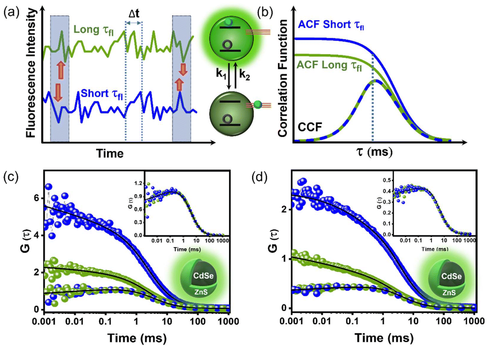 | ||
| Fig. 2 (a) Schematics of PL intensity traces of exciton (long τfl, green) and trap (short τfl, blue) states of a QD. Over time, if the PL fluctuation patterns of the two emission centers (exciton and trap) correlate in a reverse manner, an anti-correlation or growth feature would be observed in CCF. (b) Schematics of ACFs of exciton (green) and trap (blue) states, along with inter-state CCF (blue-green line) with growth feature, correlating with PL blinking depicted in (a). Since both emission centers belong to the same QD, later time decay (ms regime) of all three correlation functions follows similar timescales (τD) decided by QD diffusion. Also, the μs evolution timescale of all three correlation curves would match since this timescale (τR) is decided by trapping (k1) and de-trapping (k2) rates of charge carrier; τR = (k1 + k2)−1. (a and b) are schematic representations, not showing any real data. (c and d) ACFs and CCF of CdSe/ZnS QDs at low (c) and high (d) excitation power (real data). The inset shows the CCF of the main figure to realize the growth feature by zooming the y-axis. | ||
PL lifetime profiles at both the excitation powers fit satisfactorily to a bi-exponential decay function with characteristic timescales of ∼1.9 ns and 8.9 ns, respectively (Fig. 1c). A larger contribution of exciton state (∼8.9 ns) is observed at lower pump intensity (∼0.02 kW cm−2). Correlating with previous studies, we assigned the faster component (∼1.9 ns) to trion or trap state-mediated recombination, whereas the longer component to radiative recombination of exciton.31,53 The ACFs of the trap state with ∼1.9 ns lifetime component [G(τ)1.9×1.9] and the exciton state with ∼8.9 ns component [G(τ)8.9×8.9], as well as the CCF between trap and exciton state [G(τ)1.9×8.9], at low (∼0.02 kW cm−2) and high (∼0.2 kW cm−2) excitation powers are illustrated in Fig. 2c and d. These ACFs and CCF fit nicely to the following analytical fitting function (eqn (1)), which combines two blinking phenomena. The initial part [GR(τ)] accounts for the blinking stemming from carrier trapping (rate constant k1) and de-trapping (rate constant k2) at characteristic timescale of τR [=1/(k1 + k2)], whereas the latter part [GD(τ)] represents the blinking as a result of translational diffusion of the QDs across the excitation volume.31
 | (1) |
 | (2) |
| GD(τ) = (1 + τ/τD)−1(1 + τ/k2τD)−1/2 | (3) |
| Correlations | τ D (ms) [low/high power] | τ b (μs) [low/high power] | β [low/high power] | g [low/high power] | Fraction of time spent in trap state [k1/(k1 + k2)] [low/high power] |
|---|---|---|---|---|---|
| Conventional FCS | 3.0/3.9 | 150/100 | 0.20/0.11 | 0.5/2.5 | 0.33/0.71 |
| FLCS-ACF (8.9 × 8.9 ns) | 3.0/4.0 | 150/100 | 0.29/0.18 | 0.5/2.5 | 0.33/0.71 |
| FLCS-ACF (1.9 × 1.9 ns) | 3.2/3.8 | 150/90 | 0.13/0.50 | 2.0/0.4 | 0.33/0.71 |
| FLCS-CCF (8.9 × 1.9 ns) | 3.2/4.0 | 150/90 | 0.08/0.06 | −1/−1 |
Next, we investigated the PL intensity trajectories of individual QDs embedded in a PMMA matrix (Fig. 3). Through dot-to-dot analysis, we were able to elucidate the distinct characteristics of carrier dynamics by mitigating the influence of ensemble averaging. Single-dot measurements were conducted using confocal microscopy. Our single-dot blinking investigation has provided insights into the origin of trap states and the associated carrier dynamics. Furthermore, the results of the single-dot study qualitatively correlate with FLCS study. The first step of the single dot blinking investigation involves spin-coating an extensively diluted QD sample onto a coverslip. This diluted sample was prepared by dispersing QDs in a solution containing toluene and 1% (w/v) poly(methyl methacrylate) (PMMA). Fig. 3e illustrates the fluorescence lifetime imaging (FLIM) recorded on a small portion of the coverslip, displaying diffraction-limited spots (or dots) separated by considerable distances from each other. To confirm that each dot in the scan image represents a single QD rather than a cluster of multiple QDs, we performed a second-order photon anti-bunching study on the individual dots, which revealed sub-Poissonian photon statistics (Fig. 3b and h). Photon anti-bunching or sub-Poissonian photon statistics can be observed when photons are emitted one after another from a single emission source. Indeed, our anti-bunching study can be utilized to corroborate individual dots in scan image comprising a single QD (Fig. 3e). A pulse laser emitting at ∼422 nm with a repetition rate of ∼10 MHz was used to excite the individual dots, and PL intensity trajectories were recorded for a sufficiently long time (60 seconds) (Fig. 3 left and right panels). Simultaneously, arrival times of photons relative to the excitation pulse were recorded using TCSPC for statistical analysis of the excited state lifetime. Single-dot measurements were replicated across 70–80 dots to provide a more accurate analysis of the observed phenomenon without any biases stemming from analyzing a randomly selected QD. Fig. 3 depicts the data of a few randomly selected representatives of PL intensity traces along with the statistical distribution of intensity states at different excitation powers. Intensity histograms reveal a bimodal distribution comprising high-intensity ON states and weakly intense OFF states. The OFF-state fraction was found to increase with increasing pump intensity. This observation is attributed to trion recombination at high pump intensity, as evidenced by the nearly twofold increase in the radiative recombination rate (2kr) of the OFF state at high pump intensity compared to the recombination rate (kr) of the ON state. This will be discussed in more detail in the subsequent paragraphs.
 | ||
| Fig. 3 The figures at the left (a, d and g) and right (c, f and i) panels depict the PL intensity trajectories of three individual QDs under low (2 W cm−2) and high (20 W cm−2) pump powers. The statistical distributions of intensity states are depicted along the right y-axis of the figures on the left and right panels, showing a larger OFF state fraction at elevated pump intensity. Individual figures in the left and right panels are marked with a number identifying the particle in the lifetime scan image (e) whose PL trajectory data has been shown. (b and h) Second-order cross-correlation functions [g2(τ)] recorded in pulse mode demonstrate that the emitted photons from individual dots in (e) exhibit sub-Poissonian statistics. This indicates that each dot observed in the lifetime scan image corresponds to a single QD. | ||
The OFF states in the PL trajectory that cause blinking predominantly stem from carrier trapping. Although several mechanisms are reported for QD blinking contingent upon the materials involved and the pump intensity, they all share a commonality in being linked to trap states. Thus, we examined the statistical distribution of OFF and ON states with varying durations for individual QDs, represented by ρ(τoff) and ρ(τon), respectively (Fig. 4). To delineate the ON and OFF events in a PL intensity trace, a threshold line was positioned between the average ON and OFF intensities. Intensity states above the threshold are considered to be ON events, whereas those below the threshold are considered to be OFF states. The probability distribution of OFF-time durations [ρ(τoff)] follows a power-law kinetics, ρ(τoff) ∝ τ−moff, whereas the probability distribution of ON-time durations [ρ(τon)] follows a truncated power-law kinetics,  . The power-law exponents moff and mon here indicate the relative rates of charge de-trapping and trapping in a single QD.15 The exponential cut-off time (τC) in the ON time distribution [ρ(τon)] is crucial as it provides information on the photoionization probability [ρion] of the QD, given that ρion is proportional to 1/τC.25 Certainly, we did observe this truncation behavior of ρ(τon) plot, a signature of photo charging (Fig. S4†).
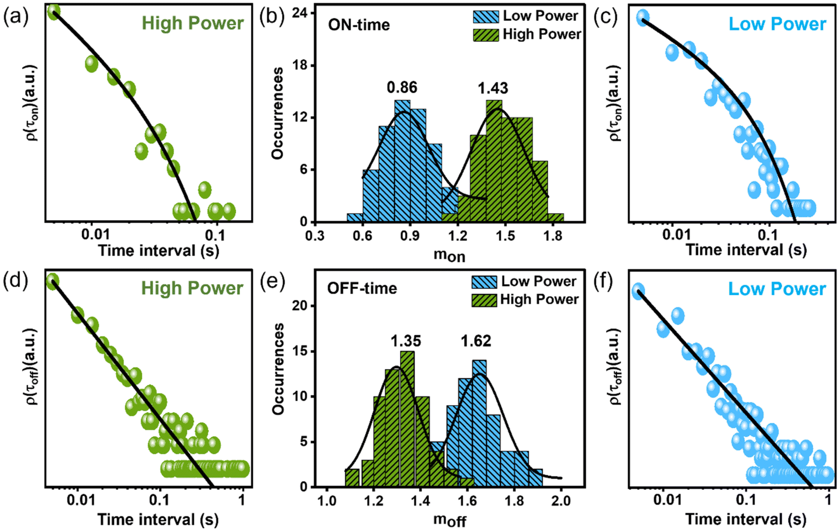 | ||
| Fig. 4 (a and c) The probability distribution plots of ON time durations of a QD at low (∼2 W cm−2, c) and high (∼20 W cm−2, a) excitation powers. (d and f) Similar plots for OFF time durations at low (∼2 W cm−2, f) and high (∼20 W cm−2, d) excitation powers. (b) Probability histograms of the ON time power law exponents (mon) recorded over 60–70 particles at low and high powers. (e) Same plots for moff at two different powers. The mean values are mentioned above each distribution. As the pump intensity increases relative charge trapping rate (mon) rate increases (b), whereas the relative charge de-trapping rate (moff) decreases (e), implying more efficient charge trapping at high power. | ||
Fig. 4b and e show the probability histograms of mon and moff, which are based on measurements from 60–70 individual QDs. As the pump intensity increases, the relative trapping rate (mon) speeds up, whereas the relative de-trapping rate (moff) slows down. This observation indicates that charge carriers are effectively trapped at high excitation power. A similar observation was also noted in the FCS study, as discussed previously. Possible models elucidating the power-dependent PL blinking of QD include (i) fluctuation of tunneling barrier with time in the pathway of carrier diffusion, where trapping occurs through tunneling of the carrier from the QD core to the external trap states.28 Excitation power here changes the PL blinking by changing the time-dependent accessibility of trap states by modulating the barrier height. Model (ii) relies on photo-charging of QDs leading to trion states where efficient Auger recombination causes the OFF state.25 The duration of the OFF state is decided by the lifetime of the carrier in the trap state. These models explain the power-law distribution of OFF-durations considering a distribution of relative distances of trap states from the core.28 Other existing models propose the involvement of hot carrier trapping and NBC recombination in the blinking process, as previously discussed. In most cases, with increasing excitation power, a greater number of recombination phenomena participate in the blinking. As a result, the cause of blinking in our QD remains uncertain, whether it can be due to the fluctuation of the tunneling barrier, the activating and deactivating of trap states, or the distribution of the density of static trap states.28,55 However, analyzing the power dependency on ρion (α1/τc) reveals a super-linear dependence on excitation power, implying Auger ionization plays a crucial role in the blinking of our QDs (Fig. S4†). We observed that 1/τc is superlinear in excitation power (i.e., ρion ∝ IP1.2), implying nonlinear (Auger ionization) and linear processes may contribute to the photo charging of our QDs (Fig. S4†).25,56–58
To illuminate the underlying mechanism of blinking in our QDs, conducting a correlation study between PL intensity and lifetime utilizing time-tagged TCSPC study at the single-particle level is essential. This study reveals a strong interdependence between these two quantities, which is more prominent in a fluorescence-lifetime-intensity-distribution (FLID) map (Fig. 5).13,18,25,41 In the FLID map, the likelihood of the dot occupying a specific state in the “IPL − τPL space” is represented by a color gradient, with red indicating higher probability and shifting to blue as the probability decreases. The FLID trajectory, connecting various probability states, provides valuable insights into the underlying mechanism of QD blinking.15,23 FLID mappings are carried out at two different powers on a set of 30–35 particles to prevent any biases that may arise from analyzing a randomly chosen QD. Subsequently, the blinking data of a particle showing the highest resemblances with other particles recorded at the same excitation power are examined further, and used for the FLID plot (Fig. 5 and S5†). The ON and OFF intensity states in a PL intensity trajectory arise from carrier recombination at the exciton state and trap state (Fig. 5a and d). These two states are clearly visible in the low-power FLID map (Fig. 5b and S6–S8†). While the ON state involves the radiative recombination of a single exciton, the OFF state encompasses several non-radiative recombination pathways along with radiative.13,25,41
 | ||
| Fig. 5 (a and d) PL intensity and lifetime trajectories, recorded on the same QD at low (a) and high (d) excitation powers. A clear correlation between lifetime and intensity trajectories was observed, implying trion and/or NBC recombination. (c and f) Excited state lifetime profiles of the OFF (blue) and ON (green) states were obtained by analyzing the emissions with intensities indicated by the blue (OFF) and green (ON) slabs in the upper panels of (a) (for (c)) and (d) (for (f)). (b and e) Fluorescence lifetime intensity distribution (FLID) maps presented in false color at low (b) and high (e) excitation powers, obtained from analyzing intensity and lifetime trajectories in (a) (low power) and (d) (high power), respectively. The shift from blue to red indicates a rising probability of a specific state occurring within the IPL − τPL space. See Fig. S5† for similar plots from other particles. | ||
Since no vertical broadening is evident in none of the FLID plots, hot carrier trapping is ruled out (Fig. 5b and e).40 Vertical broadening is generally caused by the trapping of above band-edge carriers to trap states nearby before relaxing to the band-edge state. In such a scenario, PL intensity reduces drastically without affecting the lifetime. This vertical blinking phenomenon is often referred to as B-type blinking, as illustrated by the middle figures in Scheme 1.40 To shed light on the darker species in FLID, we applied the lifetime-intensity scaling method, widely reported in the literature.13,18,25,41 As mentioned earlier, considering that the brightest state in FLID is persuasive solely to the radiative recombination of the single exciton, we can deduce the ratio of radiative rates (kr,off/kr,on) between the dark (OFF) and bright (ON) states.13 This deduction would be made under the assumption that the intensities (I) of the corresponding states in the blinking trajectory are proportional to their PL quantum yields (PLQYs). Hence, the radiative recombination rate (kr) would be proportional to PLQY/τ (or I/τ). When this relationship is applied to both ON (green slab) and OFF (blue slab) intensity states of blinking trajectory, one can obtain the relative radiative rates of ON (kr,on) and OFF (kr,off) states (Fig. 5a and d). The scaling factor η, representing the ratio of radiative recombination rates of OFF and ON states (kr,off/kr,on), provides valuable insights into the darker species. This understanding aids in distinguishing the nature of the OFF states, determining whether they are charged species prone to efficient Auger recombination or quenched neutral species (eqn (4)).
 | (4) |
 | ||
| Scheme 1 Various possible PL blinking mechanisms in a QD (upper panel), along with their corresponding appearance patterns on the FLID map (vertical figures in the lower panel). Nonradiative processes are denoted by red arrows, while radiative processes are depicted with green arrows. | ||
In the above equation, Ion (or Ioff) represents ON (or OFF) state intensity which is determined by averaging the emission intensity within the green (or blue) vertical slab in the PL intensity trajectory (Fig. 5a and d).13 Likewise, τon (or τoff) denotes the lifetime of the ON (or OFF) state's PL, which is determined by fitting the PL decay profile of the ON state to an exponential decay function (as illustrated in Fig. 5c and f). The decay profile of the ON (or OFF) state is derived from the photons collected from the green (or blue) vertical slabs of the PL intensity trajectory, as depicted in Fig. 5a and d. Scaling factor η with value unity implies that the OFF state is a neutral species caused by the NBC recombination. This form of recombination arises from the short-lived shallow trap states located near the band edge, a phenomenon commonly seen in QDs and various other semiconductor materials.28,40,59,60 NBC blinking involves an interplay between constant radiative recombination rate and fluctuating nonradiative recombination rate, leading to a linear relationship between intensity and lifetime, shown by a white dotted line in the FLID map (Fig. 5b and e). In our case, the blinking phenomenon observed in QDs under low excitation power is solely induced by band-edge carrier trapping and de-trapping, which is referred to as NBC or C-type blinking (Fig. 5a). The pathway of charge trapping in NBC recombination and its manifestation in FLID map is illustrated by the vertical figures on the right side of Scheme 1.15 As mentioned earlier, NBC blinking is caused by the shallow trap states near the band-edge and can be confirmed by calculating η. This value can be derived by analyzing the low-power PL blinking trajectory using eqn (4) (Fig. 5a). We derived the intensities of ON (Ion ∼701/20 ms) and OFF (Ioff ∼84/20 ms) states after subtracting the background intensity (∼8/20 ms) from the apparent ON and OFF state intensities of PL intensity trajectory at low excitation power (Fig. 5a). The lifetimes of ON (τon ∼15.6 ns) and OFF (τoff ∼2.2 ns) states are also derived from the same blinking trajectory (Fig. 5a), analyzing the emissions from the highest (green slab) and lowest (blue slab) intensity regimes. PL intensity decay curves are depicted in Fig. 5c. Plugging all these values into eqn (4) results in η ∼ 0.85, which is close to unity, as expected for NBC or C-type blinking, and is further confirmed by the linear trajectory observed in the FLID map (Fig. 5b).
However, a similar calculation of η for the high-power blinking trajectory reveals the involvement of an additional recombination channel, predominantly trion-mediated Auger recombination (Fig. 5d–f). For trion recombination, η would be 2, and the corresponding blinking is recognized as type-A blinking (Scheme 1). The curved trajectory of the FLID map indicates type-A blinking (Fig. 5e). In contrast to the single exponential lifetime profile observed for the OFF-state at low excitation power, the OFF-state lifetime at high excitation power comprises two components (τfastoff ∼ 0.6 ns and τslowoff ∼ 2.1 ns) (Fig. 5f). η was calculated separately for these two components, with Ion (∼1200/20 ms), Ioff (∼130/20 ms), Ibackground (∼8/20 ms), and τon (∼14 ns) being common parameters. With the faster lifetime component (∼0.6 ns) of the OFF state, our calculated value of η (∼2.5) lies close to 2, suggesting trion recombination.13 A slightly higher value of η than the expected one is likely due to the use of an overestimated Ioff, which includes contributions from another lifetime component (∼2.1 ns) that is difficult to separate. On the other hand, the longer lifetime component (∼2.1 ns) of the OFF state yields η ∼ 0.72, which is close to unity, implying NBC or C-type recombination. Thus, it is evident that at low excitation power, only type-C or NBC blinking is present in our QDs. However, at an elevated pump intensity, trion-mediated type-A blinking participates alongside type-C blinking. This assertion can be further supported by examining the trajectory of the FLID maps depicted in Fig. 5b and e. At low power, FLID trajectory shows a linear diagonal relationship (dotted white line), while at high power, an additional curved trajectory (solid white line) emerges alongside the linear one as a result of trion recombination (Fig. 5b and e). In none of the excitation powers, the PL intensity trajectory demonstrates hot carrier recombination or B-type blinking.
Our subsequent efforts to investigate the relationship between QD blinking and defect state density enabled us to analyze the FLID patterns of QDs while varying the number of defect states.23,25,76 This study was performed by enhancing defect states through the gradual photodegradation of QDs via UV irradiation. The colloidal suspension of QDs in hexane was exposed to intense UV light for an extended period (∼5 h), leading to partial photodegradation, as evidenced by a gradual decline in PLQY (Fig. S6†). UV irradiation causes long-lived deep trap states in QDs, where photoexcited charge carriers become easily trapped for long time, leading to photocharging of QDs.25 Upon excitation to these charged QDs, they transform into trions, where carriers efficiently recombine through Auger processes.23,25,76 Fig. S7–S9† displays the FLID maps of QDs subjected to varying durations of UV exposure. The FLID pattern of QDs not exposed to UV follows a linear relationship between intensity and lifetime, represented by a diagonal trajectory.23,25,76 In contrast, UV-exposed QDs show an additional FLID pattern with a curved trajectory, indicative of trion recombination, which becomes more pronounced with increased UV exposure.23,25 Therefore, we conclude that a higher density of defect states leads to the dominance of trion blinking over NBC blinking.
Conclusions
In summary, a thorough examination of carrier dynamics in a model QD system by FLCS and single particle blinking reveals several striking observations. (i) FLCS study provided evidence of carrier diffusion contributing to QD blinking. The anti-correlation feature in the μs regime of CCF is indeed a remarkable finding, suggesting a decrease in PL of exciton state at the expense of an increase in PL of the trap state, and vice versa. Thus, our FLCS study demonstrates a direct evidence of carrier diffusion, such an observation is relatively uncommon in the existing literature. Our FLCS study established further a reduced stretching exponent (β) and faster timescale of carrier dynamics (τR) at an elevated pump intensity, implying efficient carrier trapping by dispersive trap states with distributed energies at high pump intensity. Unfortunately, our FLCS study was unable to clarify the true nature of the trap states and their mechanistic involvements in blinking at different excitation powers. Analysis of our single dot PL data confirms that the origin of faster τR and dispersive trap states at high power is indeed linked to an additional relaxation channel caused by the trion recombination. At a low excitation power, only the short-lived band edge trap states participate in the blinking, which is less dispersive in nature, and also, the associated timescale of blinking here is relatively slower since it involves recombination between two oppositely charged species. However, for trion recombination at high pump intensity, one hole can recombine either of the two electrons (negative trion) or one electron with two holes (positive trion) with a much faster timescale because of the higher recombination probability. Also, unlike NBC recombination, trion recombination involves long-lived deep trap states that are highly dispersive in nature and stem from the internal structural defect of QDs.60–63 Thus, the single dot PL blinking analyses nicely explain the origins of reduced β and faster τR, observed in the FCS study of QDs at higher excitation power. Moving forward, our future plans include conducting a more in-depth analysis of charge carrier dynamics. We aim to utilize ultrafast time-resolved techniques to provide a comprehensive understanding of carrier dynamics across all timescales.64–75Data availability
The data supporting this article have been included in the ESI† and main manuscript. Constructions of FLCS, anti-bunching curves, PL intensity trajectory, distributions of ON and OFF times, FLIDs and subsequent fittings were performed using SymPhoTime 64 software developed by PicoQuant. Details of this software can be found at https://www.picoquant.com/dl_datasheets/SymPhoTime64_brochure.pdf.Conflicts of interest
There are no conflicts to declare.References
- D. A. Hines and P. V. Kamat, ACS Appl. Mater. Interfaces, 2014, 6, 3041–3057 CrossRef CAS.
- H. Zhu, N. Song and T. Lian, J. Am. Chem. Soc., 2010, 132, 15038–15045 CrossRef CAS.
- S. Kundu and A. Patra, Chem. Rev., 2017, 117, 712–757 CrossRef CAS PubMed.
- B.-O. Dabbousi, J. Rodriguez-Viejo, F.-V. Mikulec, J. R. Heine, H. Mattoussi, R. Ober, K.-F. Jensen and M. G. Bawendi, J. Phys. Chem. B, 1997, 101, 9463–9475 CrossRef CAS.
- G. Ba, Y. Yang, F. Huang, J. Wang, Y. Lu, J. Li, C. Cheng, M. Sui and J. Tian, Nano Lett., 2024, 24, 4454–4461 CrossRef CAS.
- S. Koley, M. R. Panda and S. Ghosh, J. Phys. Chem. C, 2016, 120, 13456–13465 CrossRef CAS.
- K. Bharadwaj, S. Koley, S. Jana and S. Ghosh, Chem. – Asian J., 2018, 13, 3296–3303 CrossRef CAS PubMed.
- P. Singhal and H. N. Ghosh, J. Phys. Chem. C, 2018, 122, 17586–17600 CrossRef CAS.
- E. Zenkevich, A. Stupak, C. Göhler, C. Krasselt and C. von Borczyskowski, ACS Nano, 2015, 9, 2886–2903 CrossRef CAS PubMed.
- Y.-S. Park, J. Lim, N. S. Makarov and V. I. Klimov, Nano Lett., 2017, 17, 5607–5613 CrossRef CAS.
- H. Moon, C. Lee, W. Lee, J. Kim and H. Chae, Adv. Mater., 2019, 31, 1804294 CrossRef PubMed.
- Y. Shu, X. Lin, H. Qin, Z. Hu, Y. Jin and X. Peng, Angew. Chem., Int. Ed., 2020, 59, 22312–22323 CrossRef CAS.
- M. K. Panda, D. Acharjee, A. B. Mahato and S. Ghosh, Small, 2024, 20, 2311559 CrossRef CAS.
- K. Mishra, M. Barai and S. Ghosh, J. Phys. Chem. C, 2022, 126, 16905–16918 CrossRef CAS.
- T. Kim, S. I. Jung, S. Ham, H. Chung and D. Kim, Small, 2019, 15, 1900355 CrossRef PubMed.
- N. Pathoor, A. Halder, A. Mukherjee, J. Mahato, S. K. Sarkar and A. Chowdhury, Angew. Chem., 2018, 130, 11777–11781 CrossRef.
- E. M. Thomas, S. Ghimire, R. Kohara, A. N. Anil, K.-I. Yuyama, Y. Takano, K. G. Thomas and V. Biju, ACS Nano, 2018, 12, 9060–9069 CrossRef CAS.
- E. M. Thomas, N. Pradhan and K. G. Thomas, ACS Energy Lett., 2022, 7, 2856–2863 CrossRef CAS.
- Y. Lee, D. Y. Jo, T. Kim, J. H. Jo, J. Park, H. Yang and D. Kim, ACS Appl. Mater. Interfaces, 2022, 14, 12479–12487 CrossRef CAS PubMed.
- S. Paul and A. Samanta, J. Phys. Chem. Lett., 2022, 13, 5742–5750 CrossRef CAS PubMed.
- C. T. Yuan, P. Yu and J. Tang, Appl. Phys. Lett., 2009, 94, 243108 CrossRef.
- Y. L. He, J. Chen, R. M. Liu, Y. L. Weng, C. Zhang, Y. M. Kuang, X. J. Wang, L. J. Guo and X. Ran, ACS Appl. Mater. Interfaces, 2022, 14, 12901–12910 CrossRef CAS PubMed.
- C. T. Trinh, D. N. Minh, K. J. Ahn, Y. Kang and K.-G. Lee, Sci. Rep., 2020, 10, 2172 CrossRef CAS PubMed.
- W. Fu, J. Yin, H. Cao, Z. Zhou, J. Zhang, J. Fu, J. H. Warner, C. Wang, X. Jia, G. N. Greaves and A. K. Cheetham, Adv. Mater., 2023, 35, 2304074 CrossRef CAS.
- Y.-S. Park, S. Guo, N. S. Makarov and V. I. Klimov, ACS Nano, 2015, 9, 10386–10393 CrossRef CAS PubMed.
- S. Mandal, S. Mukherjee, C. K. De, D. Roy, S. Ghosh and P. K. Mandal, J. Phys. Chem. Lett., 2020, 11, 1702–1707 CrossRef CAS.
- T. Ahmed, S. Seth and A. Samanta, ACS Nano, 2019, 13, 13537–13544 CrossRef CAS PubMed.
- A. A. Cordones and S. R. Leone, Chem. Soc. Rev., 2013, 42, 3209–3221 RSC.
- S. Doose, J. M. Tsay, F. Pinaud and S. Weiss, Anal. Chem., 2005, 77, 2235–2242 CrossRef CAS PubMed.
- P. K. Singha, T. Kistwal and A. Datta, J. Phys. Chem. Lett., 2023, 14, 4289–4296 CrossRef CAS.
- A. Das, K. Mishra and S. Ghosh, J. Phys. Chem. Lett., 2021, 12, 5413–5422 CrossRef CAS.
- D. Acharjee, A. Das, M. K. Panda, M. Barai and S. Ghosh, Nano Lett., 2023, 23, 1946–1953 CrossRef CAS PubMed.
- K. Mishra, A. Das and S. Ghosh, J. Phys. Chem. C, 2020, 124, 24115–24125 CrossRef CAS.
- S. Dey, U. Mandal, A. Adhikari, S. Ghosh and K. Bhattacharyya, Hydrogen Bonding Transfer Excited State, 2010, 1, 159–174 Search PubMed.
- S. Ghosh, A. Adhikari, S. Sen Mojumdar and K. Bhattacharyya, J. Phys. Chem. B, 2010, 114, 5736–5741 CrossRef CAS PubMed.
- S. Ghosh, U. Mandal, A. Adhikari and K. Bhattacharyya, Chem. – Asian J., 2009, 4, 948–954 CrossRef CAS PubMed.
- A. Das, D. Acharjee, M. K. Panda, A. B. Mahato and S. Ghosh, J. Phys. Chem. Lett., 2023, 14, 3953–3960 CrossRef CAS PubMed.
- S. Bhattacharyya, S. Prashanthi, P. R. Bangal and A. Patra, J. Phys. Chem. C, 2013, 117, 26750–26759 CrossRef CAS.
- S. Kundu, A. Chowdhury, S. Nandi, K. Bhattacharyya and A. Patra, Chem. Sci., 2021, 12, 5874–5882 RSC.
- C. Galland, Y. Ghosh, A. Steinbrück, M. Sykora, J. A. Hollingsworth, V. I. Klimov and H. Htoon, Nature, 2011, 479, 203–207 CrossRef CAS PubMed.
- G. Yuan, D. E. Gómez, N. Kirkwood, K. Boldt and P. Mulvaney, ACS Nano, 2018, 12, 3397–3405 CrossRef CAS PubMed.
- T. Wohland, S. Maiti and R. Macháň, An Introduction to Fluorescence Correlation Spectroscopy, IOP Publishing, Bristol, U.K., 2020. pp. 247–250 Search PubMed.
- P. Schwille and E. Haustein, Fluorescence Correlation Spectroscopy. In A tutorial for the Biophysics Textbook Online (BTOL), Biophysical Society, Rockville, MD, 2002, pp. 10–25 Search PubMed.
- P. Kapusta, R. Machań, A. Benda and M. Hof, Int. J. Mol. Sci., 2012, 13, 12890–12910 CrossRef CAS PubMed.
- J. Humpolíckova, A. Benda, J. Sýkora, R. Machań, T. Kral, B. Gasinska, J. Enderlein and M. Hof, Biophys. J., 2008, 94, L17–L19 CrossRef.
- A. Ghosh, S. Isbaner, M. Veiga-Gutierrez, I. Gregor, J. Enderlein and N. Karedla, J. Phys. Chem. Lett., 2017, 8, 6022–6028 CrossRef CAS.
- J. Chen and J. Irudayaraj, Anal. Chem., 2010, 82, 6415–6421 CrossRef CAS PubMed.
- K. Ishii and T. Tahara, J. Phys. Chem. B, 2010, 114, 12383–12391 CrossRef CAS PubMed.
- I. Gregor and J. Enderlein, Photochem. Photobiol. Sci., 2007, 6, 13–18 CrossRef CAS PubMed.
- A. Orte, M. J. Ruedas-Rama, J. M. Paredes, L. Crovetto and J. M. Alvarez-Pez, Langmuir, 2011, 27, 12792–12799 CrossRef CAS.
- T. Mokari and U. Banin, Chem. Mater., 2003, 15, 3955–3960 CrossRef.
- R. K. Ratnesh and M. S. Mehata, Spectrochim. Acta, Part A, 2017, 179, 201–210 CrossRef CAS.
- S. Paul, G. Kishore and A. Samanta, J. Phys. Chem. C, 2023, 127, 10207–10214 CrossRef CAS.
- S. Seth, N. Mondal, S. Patra and A. Samanta, J. Phys. Chem. Lett., 2016, 7, 266–271 CrossRef CAS PubMed.
- I. Y. Eremchev, A. O. Tarasevich, J. Li, A. V. Naumov and I. G. Scheblykin, Adv. Opt. Mater., 2021, 9, 2001596 CrossRef CAS.
- M. Kuno, D. P. Fromm, S. T. Johnson, A. Gallagher and D. J. Nesbitt, Phys. Rev. B: Condens. Matter Mater. Phys., 2003, 67, 125304 CrossRef.
- S. Wang, C. Querner, T. Emmons, M. Drndic and C. H. Crouch, J. Phys. Chem. B, 2006, 110, 23221–23227 CrossRef CAS PubMed.
- F. D. Stefani, W. Knoll, M. Kreiter, X. Zhong and M. Y. Han, Phys. Rev. B: Condens. Matter Mater. Phys., 2005, 72, 125304 CrossRef.
- M. Nirmal, B. O. Dabbousi, M. G. Bawendi, J. J. Macklint, J. K. Trautmant, T. D. Harrist and L. E. Brus, Nature, 1996, 383, 802–804 CrossRef CAS.
- M. Abdellah, K. J. Karki, N. Lenngren, K. Zheng, T. Pascher, A. Yartsev and T. Pullerits, J. Phys. Chem. C, 2014, 118, 21682–21686 CrossRef CAS.
- J. Meng, Z. Lan, M. Abdellah, B. Yang, S. Mossin, M. Liang, M. Naumova, Q. Shi, S. L. Gutierrez Alvarez, Y. Liu, W. Lin, I. E. Castelli, S. E. Canton, T. Pullerits and K. Zheng, J. Phys. Chem. Lett., 2020, 11, 3705–3711 CrossRef CAS PubMed.
- S. Chatterjee, M. Ghosal, K. Tiwari and P. Sen, J. Phys. Chem. Lett., 2021, 12, 546–551 CrossRef CAS PubMed.
- S. Kundu, M. Ghosh and N. Sarkar, Langmuir, 2021, 37, 9281–9301 CrossRef CAS PubMed.
- U. Mandal, S. Ghosh, S. Dey, A. Adhikari and K. Bhattacharyya, J. Chem. Phys., 2008, 128, 164505–164510 CrossRef PubMed.
- S. Koley and S. Ghosh, Phys. Chem. Chem. Phys., 2016, 18, 24830–24834 RSC.
- S. K. Mondal, S. Ghosh, K. Sahu, P. Sen and K. Bhattacharyya, J. Chem. Sci., 2007, 119, 71–76 CrossRef CAS.
- U. Mandal, S. Ghosh, G. Mitra, A. Adhikari, S. Dey and K. Bhattacharyya, Chem. – Asian J., 2008, 3, 1430–1434 CrossRef CAS PubMed.
- D. Acharjee, A. B. Mahato, A. Das and S. Ghosh, J. Phys. Chem. C, 2023, 127, 19643–19650 CrossRef CAS.
- K. Mishra, D. Acharjee, A. Das and S. Ghosh, J. Phys. Chem. B, 2021, 125, 11017–11025 CrossRef CAS PubMed.
- S. Ghosh, U. Mandal, A. Adhikari, S. Dey and K. Bhattacharyya, Int. Rev. Phys. Chem., 2007, 26, 421–448 Search PubMed.
- A. Adhikari, S. Dey, U. Mandal, D. K. Das, S. Ghosh and K. Bhattacharyya, J. Phys. Chem. B, 2008, 112, 3575–3580 CrossRef CAS PubMed.
- G. Bounos, S. Ghosh, A. K. Lee, K. N. Plunkett, K. H. DuBay, J. C. Bolinger, R. Zhang, R. A. Friesner, C. Nuckolls, D. R. Reichman and P. F. Barbara, J. Am. Chem. Soc., 2011, 133, 10155–10160 CrossRef CAS PubMed.
- K. Bharadwaj, H. Choudhary, S. Hazra and S. Ghosh, ChemPhysChem, 2020, 21, 415–422 CrossRef CAS PubMed.
- S. Chakrabarty, H. Kaur, T. Pal, S. Kar, S. Ghosh and S. Ghosh, RSC Adv., 2014, 4, 35531–35540 RSC.
- S. Ghosh, K. Sahu, S. K. Mondal, P. Sen and K. Bhattacharyya, J. Chem. Phys., 2006, 125, 054509 CrossRef PubMed.
- M. K. Panda, D. Acharjee, N. Nandi, S. Koley and S. Ghosh, Chem. – Eur. J., 2024, e202401938, DOI:10.1002/chem.202401938.
Footnote |
| † Electronic supplementary information (ESI) available. See DOI: https://doi.org/10.1039/d4nr02221a |
| This journal is © The Royal Society of Chemistry 2024 |