 Open Access Article
Synergy of strength–ductility in HfMoTaTiZr refractory high entropy alloy through Cr addition
Lei Bai†
a,
Yutong Xiao†a,
Junjun Wang*ac,
Man Xua,
Shulin Wanga,
Chuanbin Wangbc and
Jian Peng bc
bc
aHubei Key Laboratory of Plasma Chemistry and Advanced Materials, Engineering Research Center of Environmental Materials and Membrane Technology of Hubei Province, Wuhan Institute of Technology, Wuhan 430074, P.R. China. E-mail: junjunwang@wit.edu.cn
bState Key Laboratory of Advanced Technology for Materials Synthesis and Processing, Wuhan University of Technology, Wuhan 430070, P.R. China
cChaozhou Branch of Chemistry and Chemical Engineering Guangdong Laboratory, Chaozhou 521000, P.R. China
First published on 2nd January 2024
Abstract
Concurrent strength–ductility improvement of HfMoTaTiZr is achieved via Cr addition and the underlying strengthening mechanism was discussed. 4.2 at% Cr addition into HfMoTaTiZr led to the formation of a Laves phase, in addition to the BCC phase. The hardness of HfMoTaTiZrCr0.5 is 535.8 Hv0.3, 56.96% higher than the reference alloy HfMoTaTiZr. The yield strength and fracture strain of HfMoTaTiZrCr0.5 reach 1750.6 ± 80.3 MPa and 14.0 ± 2.9%, respectively, 207.5 MPa and 20.6% higher than HfMoTaTiZr. Solid solution hardening and the presence of the intermetallic Laves phase are believed to be responsible for the enhancement in strength and the formation of a reticulated structure of the Laves phase in HfMoTaTiZrCr0.5 results in the improvement in ductility.
1. Introduction
In the last few decades, the development of nickel-based superalloys has allowed a steady increase in operating temperatures of jet turbine engines, which leads to enhanced engine performance and efficiency. However, nowadays the engine operating temperatures have reached around 80% of the melting points of the materials,1,2 i.e., almost reaching the upper limit of usability, making it impossible to further increase the operating temperature. Thus, it is urgently needed to develop new materials that can withstand higher operating temperatures to achieve better performance, higher engine efficiency, and lower greenhouse gas emissions.Among various potential candidates, such as ceramics,3–5 intermetallic compounds,6,7 and refractory metals, refractory high-entropy alloys (RHEAs)8–12 have drawn considerable attention in the past decade because of their very encouraging properties, for instance, high melting points, superior mechanical properties at both room temperature and elevated temperatures,13–18 which makes RHEAs of great interest for high-temperature application. Senkov et al.18,19 first reported two RHEAs, MoNbTaW and MoNbTaVW by arc melting followed by a hot isostatic press. Both RHEAs are single-phase alloys with a body-centered cubic structure and retain good yield strength at high temperatures of 600–1600 °C. Remarkably, the yield strength of MoNbTaVW at 1000 °C reaches 842 MPa, which is significantly higher than that of Ni-based superalloys Inconel 718 and Mar-M247 that are used as high-temperature parts on jet turbine engines. However, both MoNbTaW and MoNbTaVW exhibit poor room-temperature fracture toughness and high density. Thus, Senkov et al.18 explored the possibility of replacing heavy elements W, Mo and Ta with lighter elements Ti, Hf and Zr and successfully obtained HfNbTaTiZr RHEAs, which also have a BCC crystal structure. HfNbTaTiZr possesses outstanding room temperature ductility (ε > 50%) and considerable strain hardening and its yield strength reaches 929 MPa. Intriguingly, its yield strength at elevated temperature (1000 °C) is poor, which is only 295 MPa. Thus, Juan et al.20 replaced Nb in HfNbTaTiZr with Mo. It is encouraging that the obtained as-cast HfMoTaTiZr RHEA shows high strength at both room temperature (1600 MPa) and high temperature (855 MPa), which is great progress compared with MoNbTaW and MoNbTaVW. Nonetheless, HfMoTaTiZr has a relatively high density, 10.21 g cm−3. Thus, a strategy should be developed to reduce the density of HfMoTaTiZr without sacrificing its good mechanical properties.
Among various elements, Cr is of particular interest as it is lighter than elements in HfMoTaTiZr. Several previous studies have revealed that Cr alloying in bcc RHEAs may strengthen the alloys instead of degrading their good mechanical properties.21–27 Wang et al.28 replaced Nb, Ti and Zr, respectively, with Cr and observed that a Laves phase emerged regardless of which element was substituted by Cr and a significant enhancement in strength was achieved in all cases. Similar phenomena were also observed by Fazakas et al.29 (TiZrHfNbCr) and Yan et al.30 (WMoNbTiCr). Thus, it is expected that alloying Cr in HfMoTaTiZr can not only reduce the density but also increase the room temperature mechanical properties of HfMoTaTiZr.
In this study, two RHEAs, HfMoTaTiZr and HfMoTaTiZrCr0.5 were prepared by vacuum arc melting. The influence of Cr alloying on the phase, microstructure, and room-temperature mechanical properties of the newly formed alloys was investigated and the underlying mechanism was discussed.
2. Experimental procedures
2.1 Materials preparation
All ingots with nominal compositions of HfMoTaTiZr and HfMoTaTiZrCr0.5 RHEAs were prepared by vacuum arc-melting in an inert gas atmosphere. The nominal compositions of the HfMoTaTiZr and HfMoTaTiZrCr0.5 RHEAs are provided in Table 1. All elements displayed a purity of above 99.95 wt%. In order to improve the chemical homogeneity of the alloy, each ingot was re-melted at least 5 times. Nominal compositions were accepted because the weight loss after melting did not exceed 0.5 wt%.| Composition | Hf | Mo | Ta | Ti | Zr | Cr | Total |
|---|---|---|---|---|---|---|---|
| HfMoTaTiZr | 30.0 | 16.1 | 30.4 | 8.1 | 15.4 | 0 | 100 |
| HfMoTaTiZrCr0.5 | 28.8 | 15.5 | 29.1 | 7.7 | 14.7 | 4.2 | 100 |
2.2 Materials characterization
The crystal structure of the as-cast alloys was investigated by X-ray diffractometer (XRD) (Empyrean, Panalytical) with Cu Kα radiation. The microstructure, fracture surface, and chemical composition of as-cast alloys were observed using scanning electron microscopy (SEM) (FEI Quanta 250), which is equipped with an Oxford X-act energy dispersive spectrometer (EDS). Room temperature Vickers hardness was measured by Innovatest Falcon 401AM Vickers microhardness unit with a load of 0.3 kg and a dwelling time of 15 s. Each sample was tested under identical test conditions for five times. Cylindrical samples for the compression test were 3 mm in diameter and 6 mm in height. Compression tests were performed at room temperature using the Servo-Hydraulic testing machine (Instron 5967) operating at a constant ram speed of 0.008 mm s−1. The initial strain rate is 0.001/s. The density of the samples was determined according to the Archimedes' principle.3. Results and discussion
3.1 Microstructure
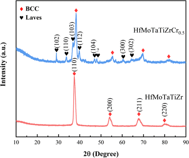
Fig. 1 shows the X-ray diffraction patterns of as-cast HfMoTaTiZr and HfMoTaTiZr0.5. HfMoTaTiZr is identified as a single-phase BCC crystal structure (cI2-W), which is identical to HfMoTaTiZr prepared by Juan et al.20 The shape of the (200), (211) and (220) peaks are asymmetric due to the compositional difference between dendrite and interdendrite regions.20 In addition to the diffraction peaks of the BCC phase, peaks corresponding to the Laves phase are also observed. The XRD-determined lattice parameters of HfMoTaTiZr and HfMoTaTiZrCr0.5 are aHfMoTaTiZr = 3.392 Å and aHfMoTaTiZrCr0.5 = 3.325 Å, respectively. Both values are higher than the calculated ones according to the ideal mixing rule or Vegard's law31 (Table 2). It is worth mentioning that the lattice parameter of HfMoTaTiZr prepared in this work is larger than that by Juan et al.20 and the relative intensity of XRD peaks (200) and (211) are different, which should be attributed to the slight difference in composition. The same as the lattice parameters, the density of HfMoTaTiZr is also higher than that measured by Juan et al.20 and the theoretical density (Table 2).| Hf | Mo | Ta | Ti | Zr | Cr | HfMoTaTiZr | HfMoTaTiZrCr0.5 | |
|---|---|---|---|---|---|---|---|---|
| Melting point | 2222 | 2610 | 2996 | 1668 | 1852 | 1907 | ||
| Lattice parameter | 3.559 | 3.147 | 3.303 | 3.276 | 3.582 | 2.884 | Cal.: 3.373 | Cal.: 3.329 |
| Exp.: 3.392 | Exp.: 3.325 | |||||||
| Density | 13.15 | 10.22 | 16.8 | 4.52 | 6.59 | 7.19 | Cal.: 10.24 | Cal.: 9.977 |
| Exp.: 10.44 | Exp.: 10.26 |
We speculated that the formation of the Laves phase in HfMoTaTiZr0.5 is attributed to the fact that Cr can form various Laves phases with the constituent elements in HfMoTaTiZr such as Ti, Zr, Hf, and Ta and Cr2X (X = Ti, Zr, Hf, and Ta) is the only stable intermetallic compound in all Cr–X binary system.32 However, we observed that the diffraction peaks of the Laves phase do not match with the standard diffraction pattern of any binary Cr2X Laves phase. Thus, we speculate that the Laves phase should be a complex multicomponent intermetallic phase, which is temporarily denoted as Cr2(Ti, Zr, Hf, Ta). Laves phases with similar composition have also been observed in several Cr-containing RHEA.28,33–35 The diffraction peaks of the BCC phase shift to higher angles with Cr addition, indicating the d-spacings decrease, i.e., the lattice constant of HfMoTaTiZrCr0.5 RHEAs is smaller than that of HfMoTaTiZrCr0.5 because Cr has the smaller atomic radius than elements in HfMoTaTiZr. Thus, it is safe to conclude that a certain amount of Cr was dissolved in the BCC phase in HfMoTaTiZr and extra Cr reacted with HfMoTaTiZr to form the Laves phase.
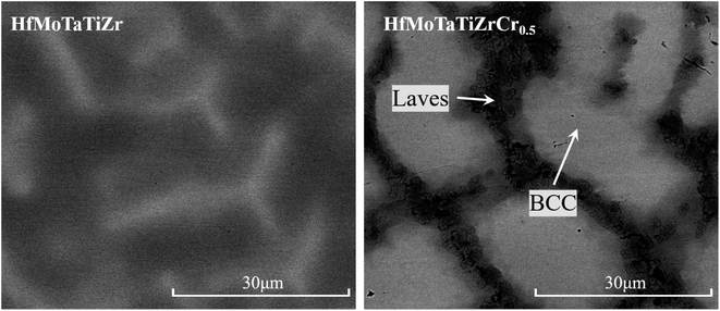
Fig. 2 shows the SEM backscatter electron (BSE) contrast images of as-cast HfMoTaTiZr and HfMoTaTiZrCr0.5. Both alloys have a typical dendrite microstructure (divided into dendritic and interdendritic regions). In contrast to HfMoTaTiZr, the elliptical dendrites in HfMoTaTiZrCr0.5 alloy are surrounded by a continuous reticulated inter-dendritic framework. The lack and granular area at the dendritic/interdendritic interface should be the Laves phase. This hypothesis is further confirmed by the element distribution maps of HfMoTaTiZrCr0.5 RHEA shown in Fig. 3. The region with Laves phase is dominated by Cr, Hf, Ti, Mo and Zr. Together with the analysis results from XRD (Fig. 1) and the conclusion from previous work,19,28,29,36–38 it is reasonable to conclude that the Laves phase should be (Cr, Mo)2(Hf, Ti, Zr). From Fig. 2, the volume fraction of the Laves phase is estimated to be 3.8%.
Table 3 summarises the EDS-determined fraction and compositions of the dendritic and interdendritic regions of as-cast HfMoTaTiZr and HfMoTaTiZrCr0.5 RHEAs. The composition of the BCC phase in both alloys are very close to each other. The dendrites are enriched in high melting point elements: Mo (2610 °C) and Ta (2996 °C), and the interdendritic regions are mainly composed of elements with relatively lower melting points: Hf (2222 °C), Ti (1668 °C), and Zr (1852 °C). Cr (1907 °C) is the dominant element in the Laves phase in HfMoTaTiZrCr0.5. and the contents of other elements range from 9.2 to 16.8 at%, which is in good agreement with the composition of the Laves phases in similar RHEAs.19,20
| Concentration (at%) | Hf | Mo | Ta | Ti | Zr | Cr | ||
|---|---|---|---|---|---|---|---|---|
| HfMoTaTiZr | Dendrite arm | BCC | 16.4 | 23.7 | 9.0 | 18.2 | 12.7 | 0 |
| Interdendrite region | BCC | 21.7 | 18.0 | 16.3 | 20.9 | 23.1 | 0 | |
| HfMoTaTiZrCr0.5 | Dendrite arm | BCC | 13.2 | 27.0 | 32.1 | 15.4 | 8.3 | 4.1 |
| Interdendrite region | BCC | 22.0 | 11.0 | 8.4 | 22.9 | 31.3 | 4.5 | |
| Laves | 16.8 | 17.3 | 9.2 | 11.9 | 16.3 | 28.5 | ||
3.2 Mechanical properties
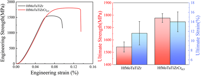
The Vickers hardness of as-cast HfMoTaTiZr and HfMoTaTiZrCr0.5 RHEAs at room temperature are also measured in the study. The addition of 4.2 at% Cr effectively increases the hardness from HfMoTaTiZr 460.1 HV0.3 to 535.8 HV0.3, increased by 16.5%. The engineering stress–strain curves of HfMoTaTiZr and HfMoTaTiZrCr0.5 obtained by compression tests at room temperature are shown in Fig. 4. The yield strength (σ0.2) of HfMoTaTiZr in this work is 1543.1 ± 40.9 MPa, which is consistent with that in ref. 20 (1600 MPa). However, the fracture strain (εf) of present HfMoTaTiZr reaches 11.6%, 65.5% higher than that of Juan et al.20 Considering the observation by XRD, it is speculated that the improved ductility or εf of HfMoTaTiZr is attributed to the slight compositional difference from that of Juan et al.20 | ||
| Fig. 4 Engineering stress–strain curves of HfMoTaTiZr and HfMoTaTiZrCr0.5 obtained by compression tests at room temperature. | ||
Compared with HfMoTaTiZr, concurrent strength–ductility improvement is achieved via the Cr addition. The σ0.2 and εf of HfMoTaTiZrCr0.5 reach 1750.6 ± 80.3 MPa and 14.0 ± 2.9%, respectively, which are 207.5 MPa and 20.6% higher than those of the present HfMoTaTiZr (1543.1 ± 40.9 MPa and 11.6 ± 4.0%). The enhancement in both σ0.2 and εf after the Cr addition can be attributed to several factors. First, XRD analysis indicates that a certain amount of Cr was dissolved in the BCC phase of HfMoTaTiZr. Cr also has the smallest atom radius among constitute elements of HfMoTaTiZr. Thus, incorporating Cr into the existing BCC unit cell will lead to more severe lattice distortions and more dislocations, i.e., solid solution hardening, which effectively promotes the hardness and strength of HfMoTaTiZr. A similar phenomenon was also observed in other RHEA.39,40 Secondly, the presence of the intermetallic phase and its dispersion can also affect the hardness and compressive strength. The Cr addition in this work leads to the formation of a hard intermetallic Laves phase, which has a positive impact on the hardness and strength of HfMoTaTiZr. Generally speaking, the appearance of the brittle intermetallic phase usually deteriorates the plasticity, i.e., leading to a decline in ductility. However, in the as-cast HfMoTaTiZrCr0.5, the Laves phase is connected and forms a reticulated structure. Such a unique structure is expected to hinder crack propagation during deformation and compensate for the loss in plasticity caused by the formation of the brittle Laves phase. In our case, the increase in ductility due to the formation of the reticulated structure is more significant than the ductility loss resulting from the increased fraction of the brittle phase.
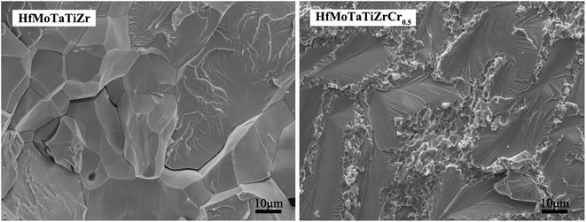
Fig. 5 shows the fracture surfaces of HfMoTaTiZr and HfMoTaTiZrCr0.5 RHEAs. HfMoTaTiZr exhibits intergranular fracture and cleavage fracture mode and a large amount of crack can be observed on the fraction surface, and intergranular fracture features mainly appear in the vicinity of cracks, together with river patterns of cleavage fracture mostly perpendicular to the grain boundary. Presumably, the fracture process is as follows: cracks initially originate in microvoids located in the dendritic/interdendritic interface and then propagate along the interface. Both intergranular fracture and cleavage fracture belong to brittle fracture. In contrast, HfMoTaTiZrCr0.5 RHEA shows a quasi-cleavage fracture surface at BCC grains. A cluster of parallel crystal planes at different heights forms because cracks propagate along certain crystal surfaces or slip surfaces, twinning surfaces, and consequently leading to the fracture of the BCC grains. However, ductile fracture is observed for the Laves phase, since its grains display the dimple fracture, indicating that the Laves phase experienced a plastic deformation during the compression test. During deformation, the extension of cracks was impeded by the reticulated structure of the Laves phase, which decreases the quantity and size of cracks and was beneficial to the plasticity. The similar effect of a reticulated structure on the plasticity has been reported by Wang et al.28
4. Conclusions
HfMoTaTiZr and HfMoTaTiZrCr0.5 RHEAs were prepared by vacuum arc melting. The effect of Cr addition on the phase, microstructure and mechanical properties was studied. The as-cast HfMoTaTiZr RHEA exhibits a single-phase BCC crystal structure while a Laves phase is present in HfMoTaTiZrCr0.5 RHEA in addition to the BCC phase. Compared with HfMoTaTiZr, concurrent strength–ductility improvement is achieved via the Cr addition. The hardness of HfMoTaTiZrCr0.5 is 535.8 Hv0.3, which is 56.96% higher than the reference alloy HfMoTaTiZr (460.1 Hv0.3). The yield strength and fracture strain of HfMoTaTiZrCr0.5 are 1750.6 ± 80.3 MPa and 14.0 ± 2.9%, respectively, which are 207.5 MPa and 20.6% higher than those of HfMoTaTiZr (1543.1 ± 40.9 MPa and 11.6 ± 4.0%). Solid solution hardening and the presence of the intermetallic Laves phase is believed to be responsible for the enhancement in strength and the formation of a reticulated structure of the Laves phase in HfMoTaTiZrCr0.5 results in the improvement in ductility.Conflicts of interest
There are no conflicts to declare.Acknowledgements
This work was supported by Guangdong Major Project of Basic and Applied Basic Research (2021B0301030001), Self-innovation Research Funding Project of Hanjiang Laboratory (HJL202202A003) and knowledge innovation project of Wuhan (2023010201010091).References
- T. M. Pollock and S. Tin, J. Propul. Power, 2006, 22, 361–374 CrossRef CAS.
- J. H. Perepezko, Science, 2009, 326, 1068–1069 CrossRef CAS PubMed.
- J. Gild, K. Kaufmann, K. Vecchio and J. Luo, Scr. Mater., 2019, 170, 106–110 CrossRef CAS.
- K. A. Kane, B. A. Pint, D. Mitchell and J. A. Haynes, J. Eur. Ceram. Soc., 2021, 41, 6130–6150 CrossRef CAS.
- R. Loehman, E. Corral, H. P. Dumm, P. Kotula and R. Tandon, Ind. Heat., 2004, 71, 36–38 Search PubMed.
- T. Yang, Y. Zhao, W. Li, C. Yu, J. Luan, D. Lin, L. Fan, Z. Jiao, W. Liu and X. Liu, Science, 2020, 369, 427–432 CrossRef CAS PubMed.
- J. Hou, J. Gan, W. Li, H. Tian, X. Luo, J. Ju, Y. Zhou, S. Liu, H. Yao and Z. Chen, Corros. Sci., 2023, 225, 111607 CrossRef CAS.
- Z. Han, H. Luan, X. Liu, N. Chen, X. Li, Y. Shao and K. Yao, Mater. Sci. Eng., A, 2018, 712, 380–385 CrossRef CAS.
- O. N. Senkov, D. B. Miracle, K. J. Chaput and J.-P. Couzinie, J. Mater. Res., 2018, 33, 3092–3128 CrossRef CAS.
- M. Srikanth, A. R. Annamalai, A. Muthuchamy and C.-P. Jen, Crystals, 2021, 11, 612 CrossRef CAS.
- W. Xiong, A. X. Guo, S. Zhan, C.-T. Liu and S. C. Cao, J. Mater. Sci. Nanotechnol., 2023, 142, 196–215 CrossRef CAS.
- Y. Shadangi, K. Chattopadhyay and N. K. Mukhopadhyay, J. Mater. Res., 2023, 38, 248–264 CrossRef CAS.
- E. Pickering and N. Jones, Int. Mater. Rev., 2016, 61, 183–202 CrossRef CAS.
- Y. Ye, Q. Wang, J. Lu, C. Liu and Y. Yang, Mater. Today, 2016, 19, 349–362 CrossRef CAS.
- E. P. George, D. Raabe and R. O. Ritchie, Nat. Rev. Mater., 2019, 4, 515–534 CrossRef CAS.
- W. Zhang, P. K. Liaw and Y. Zhang, Sci. China Mater., 2018, 61, 2–22 CrossRef CAS.
- O. Senkov, G. Wilks, D. Miracle, C. Chuang and P. Liaw, Intermetallics, 2010, 18, 1758–1765 CrossRef CAS.
- O. N. Senkov, G. Wilks, J. Scott and D. B. Miracle, Intermetallics, 2011, 19, 698–706 CrossRef CAS.
- O. Senkov, F. Zhang and J. Miller, Entropy, 2013, 15, 3796–3809 CrossRef CAS.
- C.-C. Juan, M.-H. Tsai, C.-W. Tsai, C.-M. Lin, W.-R. Wang, C.-C. Yang, S.-K. Chen, S.-J. Lin and J.-W. Yeh, Intermetallics, 2015, 62, 76–83 CrossRef CAS.
- M. del Pilar Moricca and S. Varma, J. Alloys Compd., 2010, 489, 195–201 CrossRef.
- K. Zelenitsas and P. Tsakiropoulos, Mater. Sci. Eng., A, 2006, 416, 269–280 CrossRef.
- M. Chen, X. H. Shi, H. Yang, P. K. Liaw, M. C. Gao, J. A. Hawk and J. Qiao, J. Mater. Res., 2018, 33, 3310–3320 CrossRef CAS.
- X. Gao, L. Wang, N. Guo, L. Luo, G. Zhu, C. Shi, Y. Su and J. Guo, Int. J. Refract. Met. Hard Mater., 2021, 95, 105405 CrossRef CAS.
- D. Chen, F. He, B. Han, Q. Wu, Y. Tong, Y. Zhao, Z. Wang, J. Wang and J. Kai, Intermetallics, 2019, 110, 106476 CrossRef CAS.
- S. Scudino, P. Donnadieu, K. B. Surreddi, K. Nikolowski, M. Stoica and J. Eckert, Intermetallics, 2009, 17, 532–539 CrossRef CAS.
- P. Pradhan, Y. Shadangi, V. Shivam and N. Mukhopadhyay, J. Alloys Compd., 2023, 935, 168002 CrossRef CAS.
- L. Wang, X. Li, H. Niu, L. Yang, M. Xu and J. Yi, Met. Mater. Int., 2022, 28, 2413–2421 CrossRef CAS.
- E. Fazakas, V. Zadorozhnyy, L. Varga, A. Inoue, D. Louzguine-Luzgin, F. Tian and L. Vitos, Int. J. Refract. Met. Hard Mater., 2014, 47, 131–138 CrossRef CAS.
- J. H. Yan, M. J. Li, K. Li, J. W. Qiu and Y. Guo, J. Mater. Eng. Perform., 2020, 29, 2125–2133 CrossRef CAS.
- L. Vegard, Z. Phys., 1921, 5, 17–26 CrossRef CAS.
- F. Stein and A. Leineweber, J. Mater. Sci., 2021, 56, 5321–5427 CrossRef CAS.
- X. Gao, L. Wang, N. Guo, L. Luo, G. Zhu, C. Shi, Y. Su and J. Guo, Int. J. Refract. Met. Hard Mater., 2022, 102, 105723 CrossRef CAS.
- O. Senkov, T. Daboiku, T. Butler, S. Rao and E. Payton, Int. J. Refract. Met. Hard Mater., 2022, 109, 105968 CrossRef CAS.
- H. Liu, L. Liu and C. Xin, AIP Adv., 2021, 11, 025044 CrossRef CAS.
- U. Bhandari, B. Mullamuri and S. Thangaprakash, J. Phys.: Conf. Ser., 2020, 1706, 012148 CrossRef CAS.
- S. Kumar, A. Linda, Y. Shadangi and V. Jindal, Intermetallics, 2024, 164, 108080 CrossRef CAS.
- V. K. Pandey, Y. Shadangi, V. Shivam, B. Sarma and N. Mukhopadhyay, Philos. Mag., 2022, 102, 480–503 CrossRef CAS.
- O. Senkov, J. Miller, D. Miracle and C. Woodward, Nat. Commun., 2015, 6, 6529 CrossRef CAS PubMed.
- J. Yan, K. Li, Y. Wang and J. Qiu, JOM, 2019, 71, 2489–2497 CrossRef CAS.
Footnote |
| † These authors contributed equally: Lei Bai and Yutong Xiao. |
| This journal is © The Royal Society of Chemistry 2024 |


