 Open Access Article
Effect of oxide impurities on the dissolution behavior of Th4+, Be2+ and U4+ in fluoride salts
Yubing Yan ab,
Yingjie Liab,
Haiying Fu
 a,
Yuan Qiana,
Qingnuan Lia,
Qiang Dou*ab and
Junxia Geng
 *ab
*ab
aShanghai Institute of Applied Physics, Chinese Academy of Sciences, Shanghai, 201800, China. E-mail: gengjunxia@sinap.ac.cn; Tel: +86-21-39194027
bUniversity of Chinese Academy of Sciences, Beijing 100049, China. E-mail: douqiang@sinap.ac.cn; Tel: +86-21-39190198
First published on 18th January 2024
Abstract
Oxides are one of the most important impurities in the fuel salt of molten salt reactors (MSRs), and excessive oxide impurities pose a risk to the safe operation of MSRs. This study focused on investigating the precipitation behavior between Th4+, U4+, and Be2+ with O2− in the 2LiF–BeF2 (FLiBe) eutectic salt system. The results showed that the solubility of UO2 was 5.52 × 10⁻³ mol kg−1, and the solubility product (Ksp) of UO2 was 6.14 × 10⁻⁷ mol3 kg−3 in FLiBe salt at 650 °C. It was also found that the O2− ion would firstly react with U4+ to form UO2, and then the excessive O2− would react with Be2+ to generate BeO in the FLiBe system. Despite conducting the solubility experiment of ThO2 and titration experiment of FLiBe–ThF4, the system failed to achieve the solubility and the Ksp of ThO2. The main reason for this was that O2− preferentially reacted with Be2+ over Th4+ to form precipitates, in other words, Be2+ exerted a protective effect against Th4+. Above all, this work experimentally demonstrated that in the FLiBe system, O2− preferentially combines with U4+ to form a precipitate, followed by Be2+, while Th4+ is relatively inert.
Introduction
Reducing the use of fossil fuels seems to be an effective way to reduce CO2 emissions and mitigate global warming, and many countries have chosen to develop sustainable nuclear power to partially replace traditional energy production.1 Consequently, significant efforts have been made to develop nuclear energy, and one of the current efforts is to develop the fourth-generation advanced nuclear energy systems, such as molten salt reactors (MSRs). The characteristic of MSRs is the use of nuclear fuel in liquid form.2–4 The fissile material (UF4) and fertile material (ThF4) are dissolved in the molten carrier salt, and several alternative fuel carrier salts are being considered, but the leading candidate is 2LiF–BeF2 (FLiBe).5–8 Using liquid fuel will give MSRs an excellent advantage in performing continuous on-line fuel purification. On-line refueling significantly reduces the costs associated with fuel fabrication. More importantly, the ability to perform on-line fuel processing makes MSR suitable for the use of thorium.In molten salt reactors, the purities are critical for controlling of chemical problems in the molten salt and mitigating corrosion. Among them, oxide impurities are a particularly important contaminant in this regard, because they can cause serious problems, such as fuel deposition and corrosion of structural materials.9–12 In addition to the impurities already present in the raw constituents of molten salt, partial oxide impurities are generated during reactor operation and maintenance. Water and oxygen are entrained in the gas phase of the reactor system, which are the major external sources of oxide impurities in MSRs; neutron irradiation of the fuel salt generates oxygen in the system during operation;13 and some oxides can penetrate into the MSRs fuel from passive layers formed on the surface of the structural materials.14 Although the oxide contamination in MSR is usually removed by sparging the molten salts with a mixture of H2 and HF to control the oxygen content of the molten salt within an acceptable range,15–19 after the molten salt is loaded into the reactor, oxide impurities will still be introduced slowly in the manner described above. Previous studies have shown that UF4 in the fuel salt readily reacts with O2− ions to form uranium oxide precipitates, as shown in eqn (2).20,21 The formation of uranium precipitates would reduce the concentration of U4+ and cause the loss of fuel, what's more, the large accumulation of UO2 precipitates on the structural metal surface of the primary circuit would create the overheated areas in the reactor, posing a potential threat to the reactor operation.
| H2O + 2F− = 2HF + O2− | (1) |
| UF4 + 2O2− = UO2↓ + 4F− | (2) |
For the safety of the molten salt reactor, it is necessary to strictly control the concentration of O2− in the fuel salt. In addition, the molten salt oxide chemistry of this research will open the door to a deeper understanding of the precipitation and dissolution behavior of oxides in fluoride salts, which plays an important role in the chemical control of molten salt systems.
Studies of the dissolution and precipitation behaviors of UO2 in fluoride salt have a long history, not least because of its importance in the safety of molten salt reactors. However, the existing studies showed a large scatter in the solubility product (Ksp) of UO2, and the desired data are often not available due to the inappropriate experimental conditions such as the temperature and composition of molten salt. Peng et al.20,22 have studied the precipitation of UO2 in LiF–BeF2 and LiF–NaF–KF fluoride salt systems at 600 °C, using electrochemical methods. Their study showed that the Ksp of UO2 in the LiF–NaF–KF system was 4.75 × 10⁻⁶ mol3 kg−3, while in the LiF–BeF2 system, it was 1.67 × 10⁻⁵ mol3 kg−3. There was an order of magnitude difference in the Ksp of UO2 between the two systems. Oak Ridge National Laboratory (ORNL)23 studied the Ksp of UO2 in LiF–BeF2–ThF4–UF4 at 500 °C, which was 2.60 × 10⁻⁷ mol3 kg−3. ORNL24 has studied the system in detail and found that the Ksp of UO2 at 600 °C in the LiF–BeF2–ZrF4 system was 1.20 × 10⁻⁵ mol3 kg−3. In LiF–BeF2–UF4 with the addition of 5% ZrF4, Toth25 found that Zr4+ had a greater binding interaction for O2− than that of U4+. This finding has led to an increased interest in studying the interaction between Zr4+ and O2–, as Zr4+ can effectively integrate with O2−. This property, combined with its small neutron absorption cross-section (thermal neutron absorption cross-section of 0.18 bar), has even led several researchers to advocate ZrF4 as an ideal oxygen binding additive to prevent the precipitation of UO2 in the fuel salt. Korenko21 found that the introduction of oxide in the LiF–NaF–KF–UF4–ZrF4 system can generate ZrO2 precipitation, which effectively consumed the O2− in the molten salt and prevented the precipitation of UO2. Studies of the LiF–BeF2–ZrF4–UF4 system by Peng26 showed that ZrO2 formed initially as an O2− addition of less than 1 mol kg−1, with UO2 and ZrO2 co-precipitating at O2− additions greater than 1 mol kg−1. It implied that when oxide contamination exists in the melt containing both ZrF4 and UF4, a significant amount of ZrF4 could inhibit the UO2 formation. Later, Song and co-workers27 found that in the system of LiF–BeF2–ZrF4–UF4 system, when the molar ratio of Zr4+ to U4+ was greater than 4, only ZrO2 precipitation formed after the quantitative addition of Li2O. Conversely, ZrO2 and UO2 co-precipitated when the molar ratio was less than 4.
Thorium has been acknowledged as a marvelous resource for its potential application as nuclear fuel, it has been considered as a possible supplement or even a replacement for uranium. Therefore, it is crucial to study the chemical behavior of Th4+ in thorium-based molten salt reactors, as well as that of U4+. Chamelot et al.28 reported that the addition of oxides to LiF–CaF2–ThF4 produced the intermediate product ThOF2, and gradually formed the ThO2 with more O2− added. Wang29 used Raman spectroscopy to study the addition of Li2O to FLiBe/FLiNaK–ThF4 and found that there was stabilized Th2OF104− anion with linear Th–O–Th geometry formed in both systems. Some related research on thorium utilization in molten salt reactors has been published over the years, despite the numerous investigations on the products and structures of thorium compounds, less effort has been dedicated to the precipitation and dissolution behavior of Th4+.
The influence of O2− ions on Th4+ and U4+ in the molten salt reactor has been proven to be significant. Researchers have attempted to establish an association between the precipitates of U4+, Th4+, and O2−. It is necessary to have an understanding about the solubility and solubility product (Ksp) of ThO2 and UO2. Though a few studies have been performed for the solubility and Ksp of UO2, the results obtained are inconclusive. Furthermore, to our knowledge, there is limited research about solubility and Ksp of ThO2 has been performed so far. Therefore, this study concentrates on the interaction between O2− and U4+, Th4+, as well as the precipitation and dissolution behavior of UO2 and ThO2 in the FLiBe system. This work aims to enhance knowledge of the oxide chemistry behavior in the FLiBe system.
Experiments
Solubility experiments of UO2, ThO2
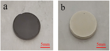
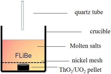
The UO2 and ThO2 (applied by North China Nuclear Fuel Components Co., Ltd) powders were compressed into tablets, as shown in Fig. 1(a) and (b), and positioned at the bottom of the crucible respectively. Next, 20 g of FLiBe salt was used to cover the tablets. To prevent any interference with sampling, a piece of nickel mesh was placed between the FLiBe molten salt and UO2/ThO2 tablet to avoid powder diffusion. The UO2 or ThO2 was immersed in the FLiBe salt bath at 650 °C to create a saturated solution, which is illustrated in Fig. 2. Samples were taken hourly during the initial seven hours and subsequently every two hours. The samples were analyzed to determine the concentration of U4+ and Th4+ by ICP-OES, while the concentration of O2− by LECO oxygen analyzer and ion chromatography. Based on the concentrations of U4+/Th4+ and O2− in salt samples, the solubility, as well as the solubility product (Ksp) can be calculated.Preparation of FLiBe–ThF4
In order to rapidly dissolve the ThF4 (supplied by Changchun Institute of Chemical Engineering, with a purity of 99.9%) into the fluoride salt, it is necessary to synthesize a molten mixture of LiF and ThF4 in advance. 10.2 g of ThF4 was mixed with 2.8 g of LiF and melted at a temperature of 700 °C to prepare LiF–ThF4(FLiTh). The FLiTh was then mixed with FLiBe salt and heated to ensure that the ThF4 uniformly dissolved into the FLiBe salt. The concentration of O2− within the resulting FLiBe–ThF4 mixture was determined to be 1.80 × 10⁻² mol kg−1.Titration experiments of UF4/ThF4 with Li2O in FLiBe
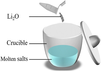
To investigate the reactions of U4+ and Th4+ with O2− in the FLiBe system and obtain the corresponding values of Ksp, the titration experiments of UF4/ThF4 in FLiBe salt were carried out. In the titration experiment of FLiBe-UF4, 1 g of UF4 (supplied by China National Nuclear Corporation, Baotou No. 202 Plant, 99.9% purity) was mixed with 19 g of FLiBe molten salt in a crucible; in the titration experiment of FLiBe–ThF4, 20 g of FLiBe–ThF4 was used. O2− ions were added to the melts in the form of Li2O. After the O2− was added, the salt mixture was stirred to ensure complete reaction of O2− ions with U4+/Th4+ ions in the salt (the schematic diagram is shown in Fig. 3). The temperature was maintained at 650 °C to allow the molten salt to settle, during the process, the supernatant was periodical extracted via a quartz tube for the concentration analysis of Th4+, U4+ and O2−.Chemical analysis
The obtained samples were dissolved and diluted, and then the concentrations of cations (U4+, Th4+) in the molten salts were determined by ICP-OES (PerkinElmer Co., Ltd.). It was based on the premise that substances form a high-temperature plasma in a high-frequency electromagnetic field, so that the constituent elements of the compounds were generated into their excited states at high temperatures or by electric excitation, and that specific wavelengths of the electromagnetic spectral lines will be emitted when the elemental excited states were restored to the ground state, thus realizing qualitative or quantitative analyses of different samples.The total concentration of O2− in the experiment was measured with the LECO oxygen detector (LECO RO600, LECO Co., Ltd.). The obtained sample was ground into powder and weighed precisely, with approximately 0.05 g sample being wrapped in a tin capsule and placed in a graphite crucible. During the test process, the molten salt sample quickly went through the feeding platform into the graphite crucible, and then switched the current to heat the crucible to 2700 °C in a short period. At the high temperature, the molten salt samples were melted, causing a reaction between the oxygen contained and carbon from the graphite crucible and generating CO and CO2 gases. The generated gases entered the infrared cell and were detected using infrared absorption. The computer assimilated the detection signals of CO and CO2 and subsequently calculated the total oxygen content value of the sample.
Weighed out about 0.1 g of sample into a PE bottle and added deionized water. The bottle was then put into an ultrasonic cleaner to extract the ions to be measured. Finally, the obtained liquid was quantitatively diluted and the oxygenated ions (NO3−, PO43−, SO42−) in the molten salt were determined using an ion chromatograph (ICS-2100, Dionex Co., Ltd).
Results and discussion
Content analysis of oxygen impurities in FLiBe salt
While the previous experiments and theoretical studies have focused on the oxygen impurity in fluoride salt, these results suggested that the oxygen impurities in the salt are composed of oxygen ions (O2−) and oxygenated anions (including NO3−, PO43−, SO42− etc.).22,30 During reactor operation and maintenance, the concentration of O2− ions within the fuel system would increase gradually, which was attributed to moisture and oxygen leaking into the reactor and the corrosion of the passive layers of the structural materials. Different from O2− ions, the oxygenated anions can be maintained at a relatively stable level, as oxygenated impurities were mainly introduced along with the carrier salt, LiF, BeF2 and UF4, etc.The total oxygen content in the FLiBe molten salt was measured using a LECO oxygen analyzer. The oxygenated anions in molten salt were determined by ion chromatography. The practical O2− concentration ([O2−]) in molten fluorides was determined by subtracting the oxide concentration in oxygenated anions ([O]IC) from the total oxide concentration ([O]LECO), as shown in eqn (3). The measurement results of the total oxide concentration and the oxide concentration in oxygenated anions of FLiBe raw materials were listed in Table 1. The average total oxide concentration in the FLiBe molten salt was up to 8.56 × 10⁻³ mol kg−1, as most of the oxygen and water contamination products were removed by sparging the salt with a mixture of H2 and HF. The main oxygenated anions were found to be NO3−, PO43−, and SO42−. Based on the mass proportion of oxide in the oxygenated anion, the oxide concentrations in NO3−, SO42−, and PO43− were determined to have oxide concentrations of 1.56 × 10⁻³, 2.13 × 10⁻³, and 3.56 × 10⁻³ mol kg−1, respectively. Thus, the resulting oxide concentrations in these three oxygenated anions were up to 7.25 × 10⁻³ mol kg−1, and the O2− content is then calculated to be 1.31 × 10⁻³ mol kg−1 using eqn (3).
| [O2−] = [O]LECO − [O]IC | (3) |
| Total oxygen content of FLiBe, mol kg−1 | Oxygen content of oxygenated anions, mol kg−1 | Total oxygen content of oxygenated anions, mol kg−1 | O2− content, mol kg−1 |
|---|---|---|---|
| 8.56 × 10⁻³ | NO3− 1.56 × 10⁻³ | 7.25 × 10⁻³ | 1.31 × 10⁻³ |
| PO43− 2.13 × 10⁻³ | |||
| SO42− 3.56 × 10⁻³ |
Solubility of UO2 in FLiBe salt
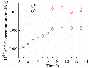
Since UO2 has been proven to be the main precipitate of U4+ ions in the fuel system,20 the key data of the solubility of UO2 in FLiBe salt is of great significance for controlling the oxide content of the fuel salt. In this study, the solubility of UO2 in FLiBe salt at a temperature of 650 °C was measured using the static dissolution method. UO2 tablet were used in these dissolution experiments. Fig. 4 shows the changes of U4+ and O2− concentrations in FLiBe salt as a function of dissolution time, where U4+ content in molten salt was regarded as the amount of UO2 dissolved. It can be seen that the U4+ concentration kept increasing with an increase in dissolution time. Finally, as the dissolution time up to 7 hours, the [U4+] reached a final plateau with a constant concentration, thus indicating that 7 h was the dissolution equilibrium time. Furthermore, the solubility of UO2 was calculated to be 5.52 × 10⁻³ mol kg−1. It should be noted that, as shown in Fig. 4, there are no significant fluctuations in the O2− concentration profile as dissolution periods greater than 7 hours. The average oxygen content was approximately 1.06 × 10⁻² mol kg−1, which is twice the U4+ equilibrium concentration, consistent with the U/O molar ratio in UO2. Based on the concentration of O2− and U4+ in FLiBe salt, the solubility product of uranium and oxygen ions was determined to be 6.14 × 10⁻⁷ mol3 kg−3, as shown in Table 2.
The titration of UF4 with Li2O in molten FLiBe
Understanding the impact of O2− on the behavior of U4+ in fluoride salt not only has fundamental interests but also is important for reactor operation and maintenance. The Ksp of UO2 is one of the most important parameters in the oxide chemistry of fuel salt, indicating the interaction between U4+ and O2− ions. This study aimed to investigate the Ksp of UO2 with different oxygen content by titrating UF4 with Li2O in FLiBe salt. Three sets of titration experiments were conducted with Li2O/UF4 ratios(molar ratio) of about 1![[thin space (1/6-em)]](https://www.rsc.org/images/entities/char_2009.gif) :
:![[thin space (1/6-em)]](https://www.rsc.org/images/entities/char_2009.gif) 1, 1
1, 1![[thin space (1/6-em)]](https://www.rsc.org/images/entities/char_2009.gif) :
:![[thin space (1/6-em)]](https://www.rsc.org/images/entities/char_2009.gif) 2, and 1
2, and 1![[thin space (1/6-em)]](https://www.rsc.org/images/entities/char_2009.gif) :
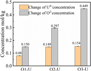
:![[thin space (1/6-em)]](https://www.rsc.org/images/entities/char_2009.gif) 3, which were called O1–U, O2–U and O3–U in this work, respectively. The equilibrium concentrations of U4+ and O2− ions in molten FLiBe salt after each titration operation are given in Table 3. According to the data in Table 3, it was found that with an increase in the addition of Li2O from 0.157 mol kg−1 to 0.470 mol kg−1, the equilibrium concentrations of U4+ decreased sharply, while the equilibrium concentration of O2− accordingly increased from 9.31 × 10⁻³ mol kg−1 to 2.13 × 10⁻² mol kg−1. Thus, based on the given data, the solubility product (Ksp) of U4+ and O2− can be calculated to be 3.80 × 10⁻⁶ mol3 kg−3. This value was slightly greater than the Ksp obtained in the UO2 solubility experiment. This may be attributed to some un-deposited UO2 particles formed in the titration experiments, and these particles were picked up with the fluoride salt in the sampling process. The Ksp of UO2 obtained from the experiment is compared with that in the literature, the results are shown in Table 4.
3, which were called O1–U, O2–U and O3–U in this work, respectively. The equilibrium concentrations of U4+ and O2− ions in molten FLiBe salt after each titration operation are given in Table 3. According to the data in Table 3, it was found that with an increase in the addition of Li2O from 0.157 mol kg−1 to 0.470 mol kg−1, the equilibrium concentrations of U4+ decreased sharply, while the equilibrium concentration of O2− accordingly increased from 9.31 × 10⁻³ mol kg−1 to 2.13 × 10⁻² mol kg−1. Thus, based on the given data, the solubility product (Ksp) of U4+ and O2− can be calculated to be 3.80 × 10⁻⁶ mol3 kg−3. This value was slightly greater than the Ksp obtained in the UO2 solubility experiment. This may be attributed to some un-deposited UO2 particles formed in the titration experiments, and these particles were picked up with the fluoride salt in the sampling process. The Ksp of UO2 obtained from the experiment is compared with that in the literature, the results are shown in Table 4.
| Initial O2−, mol kg−1 | Equilibrium U4+, mol kg−1 | Equilibrium O2−, mol kg−1 | Ksp, mol3 kg−3 | Average value | |
|---|---|---|---|---|---|
| O1–U | 0.157 | 7.51 × 10⁻² | 9.31 × 10⁻³ | 6.51 × 10⁻⁶ | 3.80 × 10⁻⁶ |
| O2–U | 0.316 | 9.61 × 10⁻³ | 1.87 × 10⁻² | 3.36 × 10⁻⁶ | |
| O3–U | 0.470 | 3.34 × 10⁻³ | 2.13 × 10⁻² | 1.52 × 10⁻⁶ |
| Molten salt system | Temperature/°C | Ksp/mol3 kg−3 | Experimental condition |
|---|---|---|---|
| LiF–BeF2 | 600 | 1.67 × 10⁻⁵ | Titration experiment |
| LiF–NaF–KF | 600 | 4.75 × 10⁻⁶ | Titration experiment |
| LiF–BeF2–ThF4–UF4 | 500 | 2.6 × 10⁻⁷ | Molten salt reactor |
| LiF–BeF2–ZrF4 | 600 | 1.2 × 10⁻⁵ | Molten salt reactor |
| LiF–BeF2 | 650 | 6.14 × 10⁻⁷ | Solubility experiment |
| LiF–BeF2 | 650 | 3.80 × 10⁻⁶ | Titration experiment |
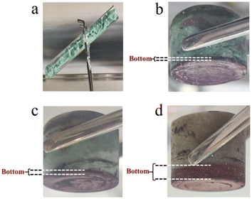
As seen in Table 3, there was a clear difference between the initial addition value and the equilibrium value of U4+ and O2− in the melts. The concentration variation of the two ions in these titration experiments is shown in Fig. 5. Inspected in more detail, it was revealed that the variation in concentration of the Δ[U4+]/Δ[O2−] ratio in the O1–U and O2–U experiments was about 1![[thin space (1/6-em)]](https://www.rsc.org/images/entities/char_2009.gif) :
:![[thin space (1/6-em)]](https://www.rsc.org/images/entities/char_2009.gif) 2, consistent with the U/O molar ratio in UO2. Fig. 6 shows the photographs of solidified FLiBe–UF4 salts after the titration experiments. It was evident that distinct reddish-brown precipitate layers appeared at the bottom of the salts. Meanwhile, with an increase in the addition of Li2O, the thickness of the precipitate layer increased, and the upper green molten salt gradually discolored. However, the results obtained in the O3–U experiment demonstrated that the Δ[U4+]/Δ[O2−] ratio was approximately 1
2, consistent with the U/O molar ratio in UO2. Fig. 6 shows the photographs of solidified FLiBe–UF4 salts after the titration experiments. It was evident that distinct reddish-brown precipitate layers appeared at the bottom of the salts. Meanwhile, with an increase in the addition of Li2O, the thickness of the precipitate layer increased, and the upper green molten salt gradually discolored. However, the results obtained in the O3–U experiment demonstrated that the Δ[U4+]/Δ[O2−] ratio was approximately 1![[thin space (1/6-em)]](https://www.rsc.org/images/entities/char_2009.gif) :
:![[thin space (1/6-em)]](https://www.rsc.org/images/entities/char_2009.gif) 2.9, which was different from the U/O molar ratio in UO2. It was found that the Δ[U4+]/Δ[O2−] ratio remained at 1
2.9, which was different from the U/O molar ratio in UO2. It was found that the Δ[U4+]/Δ[O2−] ratio remained at 1![[thin space (1/6-em)]](https://www.rsc.org/images/entities/char_2009.gif) :
:![[thin space (1/6-em)]](https://www.rsc.org/images/entities/char_2009.gif) 2.9 (shown in Table 5) upon repetition of the O3–U experiment.
2.9 (shown in Table 5) upon repetition of the O3–U experiment.
| Starting | Equilibrium | Variations | U4+:O2−percentage change | |
|---|---|---|---|---|
| U4+ mol kg−1 | 0.158 | 3.10 × 10⁻³ | 0.155 | 1![[thin space (1/6-em)]](https://www.rsc.org/images/entities/char_2009.gif) : :![[thin space (1/6-em)]](https://www.rsc.org/images/entities/char_2009.gif) 2.9 2.9 |
| O2− mol kg−1 | 0.469 | 2.35 × 10⁻² | 0.446 |
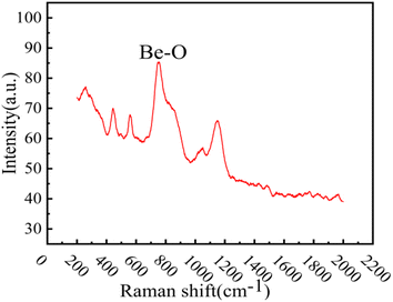
XRD analysis was performed on the reddish-brown precipitate after most of the FLiBe salt was removed (shown in Fig. 7). The diffraction peaks on the XRD pattern indicated that all the precipitate layers in these titration experiments contain a large amount of UO2. Later, these precipitates were analyzed by Raman spectrometer, and the analysis result (Fig. 8) showed that UO2 was not the only generated precipitate in the O3–U experiment. Another insoluble oxide BeO31 would form after most U4+ ions were precipitated due to the successive addition of Li2O. Such a result may explain the distinct deviation of the Δ[U4+]/Δ[O2−] ratio in the O3–U experiment.
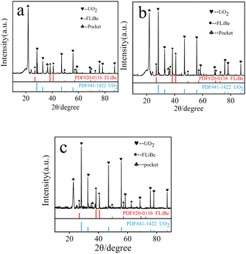 | ||
| Fig. 7 (a) XRD analysis of the precipitate in O1–U; (b) XRD analysis of the precipitate in O2–U; (c) XRD analysis of the precipitate in O3–U. | ||
Solubility of ThO2 in FLiBe salt
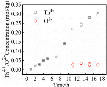
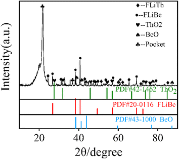
In MSRs using thorium, the deposition behavior of Th4+ is worthy of attention. Previous research have indicated that the Th4+ oxide precipitates in the form of ThO2.30 In order to study the precipitation and dissolution behavior of ThO2 in the FLiBe system, the solubility of ThO2 in molten FLiBe salt at 650 °C was studied by the static dissolution method. Fig. 9 presents the concentrations of Th4+ and O2− in the molten salt at different times. The concentration of Th4+ increased from 1.24 × 10⁻³ mol kg−1 to 0.297 mol kg−1, and did not reach dissolution equilibrium after 18 hours. However, the [O2−] fluctuated within a small range of 0.03 mol kg−1 after being dissolved for more than 10 hours, which was much less than the concentration of Th4+. The variation of concentrations was not only inconsistent with the Th/O molar ratio in ThO2 but also different from that of the UO2 solubility experiment completely. Due to the continuous dissolution of Th4+ in FLiBe without reaching equilibrium during the experiment, the solubility and Ksp of ThO2 could not be determined.To explore why ThO2 fails to reach its dissolution equilibrium just as UO2 does, XRD analysis was conducted on the insoluble substance at the bottom of molten salt after removing the FLiBe salt by distillation. As shown in Fig. 10, it can be observed that BeO and ThO2 coexisted. It was speculated that the O2− generated from dissolved ThO2 would react with Be2+, which promoted the dissolution of ThO2.
The titration of ThF4 with Li2O in molten FLiBe
It failed to get the Ksp of ThO2 from the solubility experiment, which was extremely important to control the oxygen in molten salt, so the Ksp of ThO2 was intended to be measured using the same method as the UO2 titration experiment mentioned above. Two sets of titration experiments were conducted with Li2O/ThF4 ratio of about 1![[thin space (1/6-em)]](https://www.rsc.org/images/entities/char_2009.gif) :
:![[thin space (1/6-em)]](https://www.rsc.org/images/entities/char_2009.gif) 1 and 1
1 and 1![[thin space (1/6-em)]](https://www.rsc.org/images/entities/char_2009.gif) :
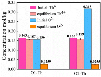
:![[thin space (1/6-em)]](https://www.rsc.org/images/entities/char_2009.gif) 2, denoted by O1–Th, O2–Th. Fig. 11 presents the initial and the equilibrium concentrations of Th4+, O2− in the molten salt, and shows a significant difference from the UO2 titration experiment. As shown in this figure, with the addition of Li2O, there was no obvious change in the concentration of Th4+, while the [O2−] decreased unexpectedly. The result suggested that the introduction of O2− may react with other cations, leading to the dissolution behavior of Th4+ to remain unaffected.
2, denoted by O1–Th, O2–Th. Fig. 11 presents the initial and the equilibrium concentrations of Th4+, O2− in the molten salt, and shows a significant difference from the UO2 titration experiment. As shown in this figure, with the addition of Li2O, there was no obvious change in the concentration of Th4+, while the [O2−] decreased unexpectedly. The result suggested that the introduction of O2− may react with other cations, leading to the dissolution behavior of Th4+ to remain unaffected.
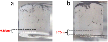
In order to determine whether the Th4+ in molten salt reacted with O2−, the concentration of Th4+ in different sections of the molten salt of O2–Th was analyzed, the relevant result was shown in Table 6. It was evident that the concentrations of Th4+ in all three parts were similar, confirming that Th4+ was uniformly distributed in the FLiBe salt. However, obvious precipitates were observed at the bottom of the salt (as shown in Fig. 12), and the thickness of the precipitate layer increased with the increase of O2−. Subsequently, an XRD analysis was performed on the precipitate after most of FLiBe salt was removed (Fig. 13). The XRD pattern confirmed the presence of BeO but no ThO2 in the precipitate.
![[thin space (1/6-em)]](https://www.rsc.org/images/entities/char_2009.gif) :
:![[thin space (1/6-em)]](https://www.rsc.org/images/entities/char_2009.gif) O2− = 1
O2− = 1![[thin space (1/6-em)]](https://www.rsc.org/images/entities/char_2009.gif) :
:![[thin space (1/6-em)]](https://www.rsc.org/images/entities/char_2009.gif) 2)
2)
| Th4+, mol kg−1 | |
|---|---|
| Upper part | 0.160 |
| Middle part | 0.162 |
| Lower part | 0.157 |
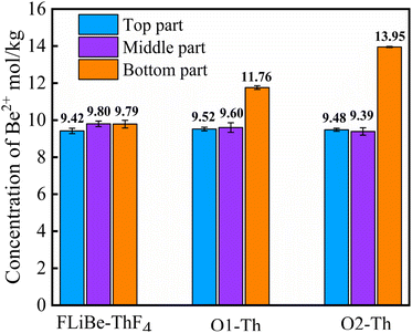
Therefore, it is necessary to determine the concentration of Be2+ in the molten salt. Fig. 14 illustrates the variation of [Be2+] at different sections within the molten salts of O1–Th, O2–Th, and FLiBe–ThF4. It can be seen that the [Be2+] remained relatively consistent across different positions in the FLiBe–ThF4 molten salt. However, in the salts of O1–Th and O2–Th, the [Be2+] at the bottom was higher than that of the top and middle sections. Furthermore, the [Be2+] at the bottom of O2–Th was higher than that of O1–Th. These experimental findings suggested that the addition of O2− led to an enrichment of Be2+ at the bottom, which could be attributed to the fact that O2− did not react with Th4+ but with Be2+ in the FLiBe system.
The comparison of binding ability of Th4+, Be2+ with O2− in fluoride salts
Based on the titration experiments results outlined above, two sets of experiments were specifically designed to investigate the interaction between Be2+, Th4+ and O2− in fluoride salts. To observe whether the Th4+ has the ability to capture the O2− from BeO, the titration experiment of ThF4 in the FLiBe was conducted by adding BeO instead of Li2O. And to examine whether O2− can combine with Th4+ to generate ThO2, the titration experiment of ThF4 with Li2O in FLiTh without Be2+ was performed.In the titration experiment of ThF4 with BeO in FLiBe, the ratio of BeO/ThF4 was set to be 1![[thin space (1/6-em)]](https://www.rsc.org/images/entities/char_2009.gif) :
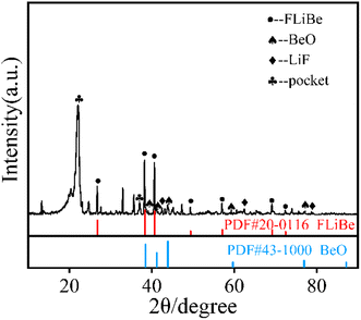
:![[thin space (1/6-em)]](https://www.rsc.org/images/entities/char_2009.gif) 2. The equilibrium [Th4+] and [Be2+] as well as the [O2−] in the supernatant of the molten salt were listed in Table 7. It showed that there was no obvious change in the concentrations of Be2+, Th4+ and O2−. However, Fig. 15(a) presents obvious precipitation at the bottom of the molten salt, and XRD characterization (the result shown in Fig. 15(b)) revealed that the precipitation was BeO. The experimental results confirmed that the BeO did not react with Th4+ in FLiBe molten salt, suggesting it is difficult for Th4+ to capture the O2− in BeO.
2. The equilibrium [Th4+] and [Be2+] as well as the [O2−] in the supernatant of the molten salt were listed in Table 7. It showed that there was no obvious change in the concentrations of Be2+, Th4+ and O2−. However, Fig. 15(a) presents obvious precipitation at the bottom of the molten salt, and XRD characterization (the result shown in Fig. 15(b)) revealed that the precipitation was BeO. The experimental results confirmed that the BeO did not react with Th4+ in FLiBe molten salt, suggesting it is difficult for Th4+ to capture the O2− in BeO.
| Th4+, mol kg−1 | Be2+, mol kg−1 | O2−, mol kg−1 | |
|---|---|---|---|
| 1 | 0.162 | 9.81 | 1.57 × 10⁻² |
| 2 | 0.160 | 9.62 | 1.75 × 10⁻² |
| 3 | 0.162 | 9.97 | 1.89 × 10⁻² |
| 4 | 0.161 | 9.61 | 1.89 × 10⁻² |
 | ||
| Fig. 15 (a) FLiBe–ThF4–BeO molten salt; (b) XRD spectrum of the precipitation of FLiBe–ThF4–BeO; (c) XRD spectrum of the precipitation of FLiTh–Li2O. | ||
In another titration experiment of ThF4, Li2O was directly added to FLiTh salt, and the precipitate obtained in this system was characterized by XRD after the removal of the molten salt (shown in Fig. 15(c)). The XRD pattern clearly revealed the presence of ThO2, indicating that Th4+ has the ability to react with O2− to form ThO2 in the absence of Be2+.
Based on the solubility experiment of ThO2 and the titration experiment of ThF4 in FLiBe salt, it was clearly demonstrated that when O2− was introduced into the FLiBe–ThF4 salt, it preferentially reacted with Be2+ rather than Th4+. This suggested that Be2+ had a protective effect on Th4+ in the fluoride salt system.
Conclusions
To investigate the effect of O2− on the fuel salt of molten salt reactor, and provide a basis for understanding the chemical behavior of oxides in the fluoride salt system, this study focused on the solubility of UO2 and ThO2, as well as the interaction behavior of O2− with U4+, Th4+, and Be2+ in the FLiBe system. The main findings are summarized as follows.(1) At a temperature of 650 °C, the solubility of UO2 was 5.52 × 10⁻³ mol kg−1, and the value of Ksp was 6.14 × 10⁻⁷ mol3 kg−3. When the added [O2−] was less than twice of the [U4+] in the FLiBe system, O2− would preferentially react with U4+ to form UO2 precipitate. As more O2− continued to be introduced, O2− would react with Be2+ to generate BeO precipitate.
(2) When O2− was introduced into the FLiBe–ThF4 system, O2− would preferentially react with Be2+ rather than Th4+, and only in the absence of Be2+, O2− reacted with Th4+ to form ThO2. In brief, O2− introduced into the FLiBe molten salt at 650 °C would react firstly with U4+, then with Be2+, and finally with Th4+.
Hence, when oxide impurities were introduced into the molten salt reactor fuel, it is important to take into account their impact on uranium to prevent the formation of UO2 precipitate. The current results indicated that the presence of a large number of U4+ and Be2+ played a certain protective role for Th4+.
Author contributions
Yubing Yan: methodology, investigation, writing – original draft, writing – review. Yingjie Li: data curation, investigation. Haiying Fu: conceptualization, methodology. Yuan Qian: conceptualization. Qingnuan Li: conceptualization, validation. Junxia Geng: writing – review, supervision, validation. Qiang Dou: writing – review, validation, project administration, resources.Conflicts of interest
There are no conflicts to declare.Acknowledgements
This work was supported by the National Natural Science Foundation of China (No. 12175303 and U2267226), Xinjiang Uygur Autonomous Region Key R&D Task Special Project (No. 2022B01039).References
- L. Mathieu, D. Heuer, R. Brissot, C. Garzenne, C. L. Brun, D. Lecarpentier, E. Liatard, A. Nuttin, E. Walle and J. Wilson, Prog. Nucl. Energy, 2006, 48, 664–679 CrossRef CAS.
- C. György and Sz. Czifrus, Prog. Nucl. Energy, 2016, 93, 306–317 CrossRef.
- J. Serp, M. Allibert, S. Delpech, O. Feynberg, V. Ghetta, D. Heuer, D. Holcomb, V. Ignatiev, J. L. Kloosterman, L. Luzzi, R. Yoshioka and D. Zhimin, Prog. Nucl. Energy, 2014, 77, 308–319 CrossRef CAS.
- O. Benes and R. J. M. Konings, J. Fluorine Chem., 2009, 130, 22–29 CrossRef CAS.
- P. Souček, O. Beneš, B. Claux, E. Capelli, M. Ougier, V. Tyrpekl, J. F. Vigier and J. M. Konings, J. Fluorine Chem., 2017, 200, 33–40 CrossRef.
- C. Forsberg, Prog. Nucl. Energy, 2005, 47, 32–43 CrossRef CAS.
- A. Nuttin, D. Heuer, A. Billebaud, R. Brissot, C. Le Brun, E. Liatard, J. M. Loiseaux, L. Mathieu, O. Meplan and E. M. Lucotte, Prog. Nucl. Energy, 2005, 46, 77–99 CrossRef CAS.
- M. L. Tan, G. F. Zhu, Z. D. Zhang, Y. Zou, X. H. Yu, C. G. Yu, Y. Dai and R. Yan, Nucl. Sci. Technol., 2022, 33, 5 CrossRef CAS.
- H. Nishimura, T. Terai, T. Yoneoka, S. Tanaka, A. Sagara and O. Motojima, J. Nucl. Mater., 2000, 283–287, 1326–1331 CrossRef CAS.
- Y. L. Wang, Q. Wang, H. J. Liu and C. L. Zeng, Corros. Sci., 2016, 103, 268–282 CrossRef CAS.
- F. Y. Ouyang, C. H. Chang, B. C. You, T. K. Yeh and J. J. Kai, J. Nucl. Mater., 2013, 437, 201–207 CrossRef CAS.
- K. M. Sankar and P. M. Singh, Corros. Sci., 2022, 206, 110473 CrossRef CAS.
- S. Q. Guo, J. S. Zhang, W. Wu and W. T. Zhou, Prog. Mater. Sci., 2018, 97, 448–487 CrossRef CAS.
- N. J. Condon, S. Lopykinski, F. Carotti, K. E. Johnson and A. Kruizenga, ACS Omega, 2023, 8, 29789–29793 CrossRef CAS PubMed.
- R. D. Scheele, A. M. Casella and B. K. McNamara, Ind. Eng. Chem. Res., 2017, 56, 5505–5515 CrossRef CAS.
- D. A. Petti, G. R. Smolik, M. F. Simpson, J. P. Sharpe, R. A. Anderl, S. Fukada, Y. Hatano, M. Hara, Y. Oya, T. Terai, D. K. Sze and S. Tanaka, Fusion Eng. Des., 2006, 81, 1439–1449 Search PubMed.
- A. L. Mathews and C. F. Baes Jr, Inorg. Chem., 1968, 7, 373–382 CrossRef CAS.
- P. Calderoni, P. Sharpe, H. Nishimura and T. Terai, J. Nucl. Mater., 2009, 386–388, 1102–1106 CrossRef CAS.
- S. Delpech, C. Cabet, C. Slim and G. S. Picard, Mater. Today, 2010, 13, 34–41 CrossRef CAS.
- H. Peng, M. Shen, Y. Zuo, X. X. Tang, R. Tang and L. D. Xie, Electrochim. Acta, 2016, 222, 1528–1537 CrossRef CAS.
- M. Korenko, M. Straka, J. Uhlíř, L. Szatmáry, M. Ambrová and M. Šimurda, J. Radioanal. Nucl. Chem., 2014, 302, 549–554 CrossRef CAS.
- H. Peng, W. Huang, L. D. Xie and Q. N. Li, J. Nucl. Mater., 2020, 531, 152004 CrossRef CAS.
- Molten-salt Reactor Program: the Development Status of Molten-Salt Breeder Reactors, ORNL-4812, 1972 Search PubMed.
- Molten-salt Reactor Program: Semiannual Progress Report for Period Ending, ORNL-3419, 1963 Search PubMed.
- L. Toth, U. Gat, G. Del Cul, S. Dai and D. Williams, Review of ORNL's MSR technology and status, Oak Ridge National Lab., 1996 Search PubMed.
- H. Peng, Y. L. Song, N. Ji, L. D. Xie, W. Huang and Y. Gong, RSC Adv., 2021, 31, 18708–18716 RSC.
- Y. L. Song, M. Shen, S. F. Zhao, R. Tang, L. D. Xie and Y. Qian, J. Electrochem. Soc., 2021, 168, 036513 CrossRef CAS.
- P. Chamelot, L. Massot, L. Cassayre and P. Taxil, Electrochim. Acta, 2010, 55, 4758–4764 CrossRef CAS.
- C. Y. Wang, X. T. Chen and Y. Gong, J. Phys. Chem., 2021, 125, 1640–1646 CrossRef CAS PubMed.
- M. Y. Xie, L. Li, Y. P. Ding and G. X. Zhang, J. Nucl. Mater., 2017, 487, 317–322 CrossRef CAS.
- S. M. Lee, Y. Jiang, J. Jung, J. H. Yum, E. S. Larsen, C. W. Bielawski, W. Wang, J. H. Ryoue, H. S. Kimf, H. Y. Chaf and J. Oh, Appl. Surf. Sci., 2019, 469, 634–640 Search PubMed.
| This journal is © The Royal Society of Chemistry 2024 |

