 Open Access Article
An innovative Z-type Sb2S3/In2S3/TiO2 heterostructure: superior performance in the photocatalytic removal of levofloxacin and mechanistic insight†
Jianrou Li,
Zhuangzhuang Yin ,
Jun Guo,
Wei Gan,
Ruixin Chen,
Miao Zhang
 * and
Zhaoqi Sun*
School of Materials Science and Engineering, Anhui University, Hefei 230601, Anhui Province, P. R. China. E-mail: szq@ahu.edu.cn; zhmiao@ahu.edu.cn
First published on 7th February 2024
Abstract
In this study, Sb2S3/In2S3/TiO2 (SIT) heterojunction photocatalysts were prepared by a simple two-step hydrothermal method and applied to the photocatalytic degradation of levofloxacin (LEV). After 160 min of reaction under visible light, the SIT heterojunction photocatalyst degraded 10 mg L−1 LEV at a rate of 86.7%. The degradation of LEV follows pseudo-first-order kinetics with a rate constant 1.16 × 10⁻² min−1, which is 1.42, 1.22 and 1.05 times higher than that of TiO2, SI and IT, respectively. Meanwhile, the SIT photocatalysts also showed high photocatalytic activity for other antibiotics. The enhanced photocatalytic activity of the ternary heterostructures was attributed to the full-spectrum response and the synergistic effect of the dual Z-type heterojunctions, which improved the visible light absorption and facilitated the charge separation. In addition, ˙OH and ˙O2− play a dominant role in the photodegradation process. This work contributes to the design of novel photocatalytic materials with dual Z-type heterojunctions and efficient photocatalysts for the degradation of antibiotics.
1. Introduction
Levofloxacin (LEV) is a third-generation fluoroquinolone antibiotic widely used in human and animal therapy.1–3 However, due to its complex structure and multiple physicochemical characteristics, it is difficult to completely remove LEV by conventional wastewater treatment techniques, thus it is a serious threat to ecosystems and human health.4–6 Therefore, it is crucial to explore efficient, direct, eco-friendly and sustainable methods to detect and remove antibiotics from wastewater. Photocatalysis technology based on semiconductor materials has obvious advantages of low cost, environmental friendliness and low-energy, and was considered to be a green chemical pathway with great potential for the treatment of antibiotic wastewater.7–10 Recently, researchers have studied and developed various photocatalytic materials for the degradation of antibiotics in water. For example, a novel oxygen vacancy-rich Bi5O7BrxI1−x nanorod solid solution was used for the degradation of antibiotic levofloxacin under visible light;11 construction and actual application of In2O3/BiOBr heterojunction for effective removal of ciprofloxacin under visible light;12 S-scheme heterojunction composite of UiO-66-NH2/Bi7O9I3 was applied for the degradation of ciprofloxacin.13Many semiconductor materials have been designed for photocatalytic degradation of LEVs in wastewater. Among them, titanium dioxide (TiO2) has low toxicity and good stability, and thus has a wide application potential in water treatment and environmental remediation.14,15 However, the catalytic performance of pure TiO2 is affected by the wide band gap (3.2 eV) and high photogenerated carrier recombination rate.16–18 In order to improve its photocatalytic activity and stability in practical applications, many methods have been proposed, such as optimising the structure of TiO2 and constructing heterostructures.19–21
Since the photocatalytic degradation of antibiotics occurs at the semiconductor–water interface, vertically aligned semiconductor nanoarrays (e.g., nanorods or nanosheets) provide a large number of active sites, reduce carrier diffusion distances and enable multiple light reflections between arrays, which can enhance the photocatalytic degradation of LEVs by improving the photo-generated charge separation efficiency of photocatalyst.22,23 At the same time, it can also reduce the risk of secondary pollution and improve the environmental friendliness of the wastewater treatment process. More importantly, TiO2 nanorod arrays provide an exploitable platform for building heterojunction structures. For example, Gan et al. used Ag nanoparticles to decorate 2D/2D TiO2/g-C3N4 heterojunction for efficient removal of tetracycline hydrochloride;24 Guo et al. developed a new high-performance ternary photocatalyst based on the co-modification of TiO2 nanorods with BPQDs and Ag nanoparticles for TC degradation.25
Fortunately, the above shortcomings of TiO2 can be ameliorated effectively by developing a Z-type heterojunction photocatalyst, which can remarkably improve the redox ability of catalysts through enhancing the charge separation efficiency.26–28 Alternatively, indium sulfide (In2S3) has been widely used as a photocatalyst because of its narrow band-gap (2.0–2.3 eV), wide visible light response range and low toxicity.29–31 On the other hand, antimony trisulfide (Sb2S3) has attracted much attention owing to its narrow band-gap (1.5–1.9 eV), large absorption coefficient and so on.32,33 In2S3 and Sb2S3 have been chosen to design Z-type composites because of their higher conduct band potential and lower valence band potential.34,35 According to previous literature, In2S3 and Sb2S3 have been employed to assemble Z-scheme photocatalysts coupling with other catalysts. Such as, Ding et al. prepared In2S3/TiO2 thin-film catalysts with sulfur vacancies for the activated sodium persulfate (PMS) photocatalytic degradation of levofloxacin;36 Sharma et al. fabricated nanoflower-like Sb2S3/SiO2 monoliths by the vacuum impregnation method, which were utilized for the photocatalytic degradation of pollutants MB, TM and real wastewater.37
In conclusion, binary Z-scheme photocatalysts have made enough efforts, but their photocatalytic activities still have an improvement room.38,39 Some studies reported that the successfully synthesized dual Z-type photocatalysts improved the separation/transport efficiency of photogenerated carriers, broadened the photo-response range, and thus enhanced the photocatalytic activity.40–43 For instance, Jang et al. constructed TiO2/CdS/MoS2 heterojunctions to enhance the photoelectrochemical performance;44 Shihan Qi et al. successfully synthesized In2S3/Ag–Ag2S–AgInS2/TNR photocatalyst by a facile hydrothermal and wet chemical method to enhance the photoelectrochemical and photocatalytic performance;45 Chen et al. constructed Sb2S3/CdS/CdIn2S4 S-scheme heterojunction to improve the photoelectrochemical performance.46
In this paper, Z-type Sb2S3/In2S3/TiO2 (SIT) heterojunction photocatalysts was prepared by a simple two-step hydrothermal method, which was evaluated the performance in the degradation of multiple antibiotics in the visible light and investigated the effect of different experimental parameters on the degradation of levofloxacin (LEV) by SIT. Meanwhile, the main radicals in the photocatalytic system were identified by trapping experiments and electron spin resonance spectroscopy (EPR), and the degradation pathways and intermediates of LEV were revealed by liquid chromatography-mass spectrometry (LC-MS) analysis and three-dimensional excitation-emission matrix fluorescence (3D EEMs). In addition, the energy band structure of the Z-type heterojunction was formulated by the optical and photoelectrochemical properties of the SIT system, and the degradation steps and mechanism of the Z-type SIT photocatalyst were proposed.
2. Experimental
2.1. Material
Fluorine-doped tin oxide (FTO) conducting glasses were obtained from Wuhan Jingge Solar Energy Technology Co., Ltd. Tetrabutyl titanate (C16H36O4Ti, TBT) and thioacetamide (C2H5NS, TAA) were obtained from Shanghai Aladdin Biochemical Technology Co., Ltd. Hydrochloric acid (HCl), acetone (C3H6O), ethanol, sodium thiosulfate pentahydrate (Na2S2O3·5H2O), and isopropyl alcohol (IPA, ˙OH scavenger) were obtained from Sinopharm Chemical Reagent Co., Ltd. Ethylene glycol (C2H6O2), L-antimony potassium tartrate (C8H4K2O12Sb2·xH2O), indium(III) chloride tetrahydrate (InCl3·4H2O), levofloxacin (LEV), and p-benzoquinone (BQ, ˙O2− scavenger) were obtained from Macklin Industries Co. Ltd. Ethylenediaminetetraacetic acid disodium (EDTA–2Na, h+ scavenger) were obtained from Beijing Innochem Science & Technology Co., Ltd. 5,5-Dimethyl-1-pyrroline-N-oxide (DMPO) was purchased from Dojindo Chemical Co., Ltd. All chemicals were used as received without further purification.2.2. Preparation of TiO2 nanorods arrays
Synthesis of TiO2 nanorods arrays was made by hydrothermal method. Typically, 0.5 mL of Ti(C4H9O)4 precursor was added to 30 mL aqueous solution of 6 M HCl to form a uniform system under stirring. The solution was then transferred to a polytetrafluoroethylene (PTFE) reactor liner (50 mL) and FTO of 2 cm × 5 cm was immersed in the solution. Heating at 150 °C for 12 h. After cooling, the precipitate was washed with deionized (DI) water and ethanol. And dried at 60 °C in an oven overnight.2.3. Preparation of Sb2S3/In2S3/TiO2
The fabrication procedure of Sb2S3/In2S3/TiO2 is illustrated in Scheme 1. 30 mg of TAA and 6 mg of InCl3·4H2O were dissolved in 40 mL of ethylene glycol solution. After stirring for 30 min, 10 mg of C8H4K2O12Sb2·xH2O was added to it and stirred for another 30 min, and the prepared TiO2 nanoarrays were immersed in the solution and heated at 140 °C for 12 h to obtain Sb2S3/In2S3/TiO2, defined as SIT. In the absence of InCl3·4H2O, single-phase In2S3/TiO2 can also be prepared in a similar method and denoted as IT, Sb2S3/In2S3 was fabricated by a similar procedure in the absence of TiO2, defined as ESI.†2.4. Characterization
The X-ray diffraction (XRD, D8 Advance, Bruker) analyses was performed with a scanning range from 10° to 80° to identify the crystal structures of the samples. The surface morphology of the samples was revealed by field-emission scanning electron microscopy (FESEM, Hitachi S-4800). The microstructure and lattice spacing were analyzed by transmission electron microscopy (JEOL, JEM-F200), which attached energy-dispersive X-ray (EDX) spectroscopy. X-ray photoelectron spectroscopy (XPS; ESCALAB-250) was selected to explore the surface chemical compositions with an Al Kα source. Using the Thermo Avantage software fit the data and the 284.8 eV C 1s internal standard peak as the calibration point. The ultraviolet photoelectron spectroscopy (UPS) data were equipped with He I (21.22 eV) as the UV excitation source. The time-resolved photoluminescence (TRPL) spectra of the samples were obtained by ultrafast time-resolved fluorescence spectrometer (FluoroMax-4P) with an excitation wavelength of 375 nm. The electron paramagnetic resonance (EPR) spectra were performed using an electron paramagnetic resonance spectrometer (Bruker EMX Plus). The intermediates produced during the degradation of LEV were determined by liquid chromatography-tandem mass spectrometry (LC-MS).The analytical methods were provided in ESI.†
2.5. Optical and photoelectrochemical measurements
A fluorescence spectrophotometer (FL, Hitachi F-4500) at a wavelength of 325 nm was used to analyze the separation efficiency of electron–hole pairs. And three-dimensional excitation–emission matrix fluorescence spectrum (3D EEMs) was measured to monitor the fluorescence change during the process of LEV degradation. UV-vis diffuse reflectance spectra (UV-vis DRS) was acquired using a UV-visible spectrophotometer (Shimadzu, UV-2550) and transformed into absorption spectra.A three-electrode electrochemical workstation (CHI660D) was used to performed the photocurrent response and electrochemical impedance spectroscopy (EIS). 0.1 M Na2SO4 solution as electrolyte, sample as working electrode, platinum wire as counter electrode and saturated Ag/AgCl electrode as reference electrode.
2.6. Photocatalytic tests
The photocatalytic performances of all samples were irradiated under a 300 W Xe lamp (Perfect light, PLS-SXE300/300UV). All samples (1 cm × 1 cm) were placed into LEV solution (5 mL, 10 mg L−1) for 30 min under dark condition to achieve the adsorption–desorption balance. The distance between the sample and the light source was set to 10 cm. The intensity of the characteristic absorption peak of the LEV solution was measured by UV-vis spectrophotometer every 30 min. The initial pH for assessing LEV-catalyzed degradation was adjusted with 0.10 M HCl and 0.10 M NaOH.Additional information is available in the ESI.†
3. Results and discussion
3.1. Structure and morphology characterization
X-ray diffraction (XRD) pattern of SIT is depicted in Fig. 1(a). Neglecting the diffraction peaks of FTO, the characteristic peaks at 36.1°, 54.3°, 62.8° and 69.8° can be identified as the (1 0 1), (2 1 1), (0 0 2) and (1 1 2) planes of rutile TiO2 (JCPDS 21-1276), respectively. And the peaks at 27.5°, 33.4° and 43.8° belong to (3 1 1) and (4 4 0) planes of In2S3 (JCPDS 32-0456), respectively. Moreover, the peak at 15.7° and 17.5° are ascribed to (2 0 0) and (1 2 0) planes of Sb2S3 (JCPDS 42-1393). TiO2 and IT were also synthesized as control samples as shown in Fig. S1(a) and (b).† The main diffraction peaks of SIT coincide with the planes of TiO2, In2S3, and Sb2S3, respectively.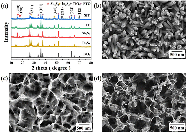 | ||
| Fig. 1 (a) XRD patterns of pure TiO2, In2S3, Sb2S3, IT and SIT; SEM images of (b) TiO2, (c) IT, (d) SIT. | ||
The SEM image shows the vertically aligned TiO2 nanorods are uniformly distributed on the FTO surface with an average width of 120 nm (Fig. 1(b)) and a length of about 1 μm (Fig. S2(a)†). To better disclose the interface effect of SIT heterostructure nanoarrays, those single-phased In2S3 and Sb2S3 were also prepared. As revealed in Fig. S2(b) and (c),† the In2S3 shows the wrinkled nanosheet structure and the Sb2S3 displays the particle structure. In Fig. 1(c), the obtained IT composites possess similar morphology to pristine In2S3. After anchoring the nanoparticles of Sb2S3, the SEM image of SIT in Fig. 1(d) also clearly presents wrinkled structure nanoarrays that were assembled by small nanosheets, as revealed by the SEM image of In2S3 and IT. The cross-section view of SIT displays still vertically aligned nanorods arrays in Fig. S2(d).†
As depicted in Fig. 2(a), TEM image of SIT can be clearly seen that the Sb2S3 nanoparticles and In2S3 nanosheets are successfully anchored on the TiO2 nanorods, confirms the intimate contact of the In2S3 and Sb2S3 with TiO2 nanorods. The highresolution transmission electron microscope image (HRTEM) in Fig. 2(b) suggests three types of clear lattice fringes of 0.32 nm, 0.20 nm and 0.35 nm are respectively attributed to the (1 1 0) plane of TiO2, the (5 1 1) plane of In2S3 and the (1 3 0) plane of Sb2S3. In addition, high-angle annular dark-field scanning TEM (HAADF-STEM) image and energy-dispersive X-ray spectroscopy (EDS) mapping images in Fig. 2(c)–(h) observe that all the Ti, In, Sb, O, and S elements were distributed on the whole nanoarrays, which also verifies the above characterizations. Above observations suggest the successful fabrication of heterostructured SIT nanoarray.
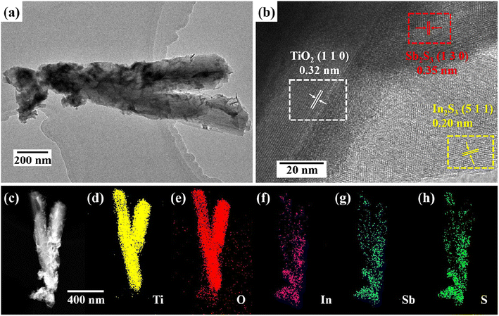 | ||
| Fig. 2 TEM images of the SIT (a); HRTEM images of a representative region (b); HAADF-STEM image (c); EDS mapping results of SIT (d)–(h). | ||
XPS analysis was also employed to investigate the chemical state and elemental composition of as-synthesized samples.47 As shown in Fig. 3(a), the XPS survey spectrum of SIT confirm the existence of expected Ti, In, Sb, S, and O elements, which is consistent with the elemental mapping analysis. Seen from the Ti 2p spectrum of Fig. 3(b), two characteristic peaks of Ti4+ state in TiO2 could be determined as Ti 2p3/2 at 458.6 eV and Ti 2p1/2 at 464.4 eV. After manufacturing SIT, the Ti 2p3/2 and Ti 2p1/2 peaks exhibit a negative shift to the binding energies of 458.5 eV and 464.3 eV. As for O 1s spectra in Fig. S3(a),† deconvoluted O 1s peak consists of 531.1 and 530.1 eV, ascribed to the ˙OH group of surface adsorbed H2O and Ti–O bond in the structure of TiO2, respectively.24,48 Similarly, the peaks for O 1s of SIT also indicate slight negative shift.
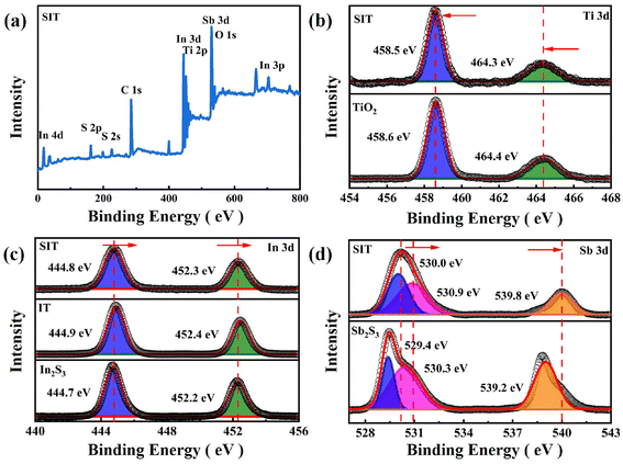 | ||
| Fig. 3 XPS spectra of different samples: (a) survey spectra, (b–d) the high-resolution spectra of Ti 2p, In 3d and Sb 3d. | ||
The In 3d spectrum in Fig. 3(c) reveals that two peaks of In2S3 are fitted into 2p1/2 at 452.2 eV and 2p3/2 at 444.7 eV. Compared with In2S3, the characteristic peaks of SIT are positively shifted by 0.1 eV. Fig. 3(d) presents the Sb 3d spectrum, the peaks of Sb2S3 at 529.4 and 539.2 eV are assigned to Sb 3d5/2 and Sb 3d3/2 of Sb3+. Similarly, the Sb 3d spectrum of SIT also displays a shift toward the higher binding energy direction. In addition, the peak at 530.9 eV could be attributed to the oxidation of the catalyst surface in the air.32,46 The S 2p spectrum in Fig. S3(b)† is segmented into the peaks at 161.3 and 162.5 eV, attributed to S 2p1/2 and S 2p3/2 of SIT, respectively.
Furthermore, the binding energy of an element is closely related to its density of outer electrons.27,40 The abovementioned analysis confirms that the binding energies of TiO2 move towards a high energy region, while the binding energies of In2S3 and Sb2S3 offset to a low energy region, which implies a low electron density of TiO2 and a high electron density of In2S3 and Sb2S3 in the heterostructure of SIT. The phenomenon demonstrates that the electrons migrate from TiO2 to In2S3 and Sb2S3 in the Z-type heterojunction of SIT.
3.2. Photocatalytic activity
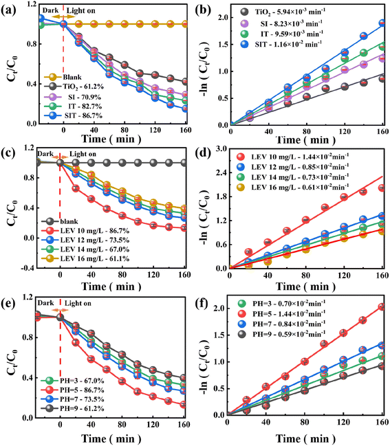
For all produced photocatalysts, the removal rate (η) and kinetic constants (Ka) of LEV photodegradation were determined using eqn (S1) and (S2),† and the results are shown in Fig. 4(a) and (b) and S4(b).†![[thin space (1/6-em)]](https://www.rsc.org/images/entities/char_2009.gif) 25,36 The η of TiO2 degradation of LEV was about 61.2% with a Ka of 5.94 × 10⁻³ min−1, which could be attributed to its broad forbidden band and low visible light reactivity of the photocatalyst. When compared to the pure TiO2 photocatalyst, the composites of IT and SI demonstrated superior photocatalytic performance (η = 82.7%, Ka = 9.59 × 10⁻³ min−1 and η = 70.9%, Ka = 8.23 × 10⁻³ min−1). In particular, when the SIT double Z-type heterojunction composite was utilized as a photocatalyst (Fig. S4(b)†), 86.7% of the LEV was degraded (Ka = 1.16 × 10⁻² min−1), which was 1.42, 1.22 and 1.05 times higher than that of TiO2 SI and IT, respectively. These facts imply that the synergistic effect produced by building a dual Z-type heterojunction delivers the maximum photocatalytic activity of SIT composites, which can be employed as an easily recyclable photocatalyst for efficient LEV degradation. Thus, the following explanations for the greater catalytic activity of SIT:
25,36 The η of TiO2 degradation of LEV was about 61.2% with a Ka of 5.94 × 10⁻³ min−1, which could be attributed to its broad forbidden band and low visible light reactivity of the photocatalyst. When compared to the pure TiO2 photocatalyst, the composites of IT and SI demonstrated superior photocatalytic performance (η = 82.7%, Ka = 9.59 × 10⁻³ min−1 and η = 70.9%, Ka = 8.23 × 10⁻³ min−1). In particular, when the SIT double Z-type heterojunction composite was utilized as a photocatalyst (Fig. S4(b)†), 86.7% of the LEV was degraded (Ka = 1.16 × 10⁻² min−1), which was 1.42, 1.22 and 1.05 times higher than that of TiO2 SI and IT, respectively. These facts imply that the synergistic effect produced by building a dual Z-type heterojunction delivers the maximum photocatalytic activity of SIT composites, which can be employed as an easily recyclable photocatalyst for efficient LEV degradation. Thus, the following explanations for the greater catalytic activity of SIT:
(1) The TiO2 vertical nanorod array is distinct in that it has a large specific surface area and more ion transport channels than other structure, which can expose an increasing number of active sites and make them more favorable for reactant adsorption.22,45
(2) The dual Z-type heterostructure, which fosters contact and a synergistic effect among the three materials, achieves successful charge separation and transfer. Additionally, the production of many reactive radicals speeds up the photocatalytic degradation of SIT system.38,43
(3) With the addition of Sb2S3 component, the visible light absorption range of the composites increased and the light absorption ability of SIT was improved.32,37
3.3. Universality, reusability and stability
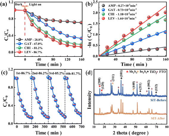
As shown in Fig. 5(a), (b) and S4(e),† the prevalence and usefulness of SIT heterojunctions were determined by the degradation efficiency of various antibiotics, including ampicillin (AMP), gatifloxacin (GAT), chlortetracycline hydrochloride (CHI) and levofloxacin (LEV) to assess their applicability. Surprisingly, under the same experimental conditions, SIT heterojunctions showed good degradation of CHI and LEV with removal efficiencies of 86.7% and 81.2%, respectively, and Ka values of 1.44 × 10⁻² min−1 and 1.18 × 10⁻² min−1, while it showed weaker degradation of GAT and AMP with degradation efficiencies of 67.0% and 28.8%, and Ka values of 0.73 × 10⁻² min−1 and 0.27 × 10⁻² min−1. The intrinsic molecular structure of the antibiotic may be responsible for the significant difference in Ka values. These results confirm that SIT dual Z-type heterojunctions show wide applicability in degrading various antibiotics.The reusability and stability of the catalysts were investigated to assess their potential for practical applications. As seen in Fig. 5(c), even though the LEV removal efficiency showed a slight decreasing trend as the cycle number increased, the degradation rate of LEV by the SIT dual Z-type heterojunction photocatalyst could still reach 81.7% after four consecutive cycles, indicating that the system has a relatively beneficial cycling performance. Since oxygen-containing functional groups are the primary active ingredient in the degradation of LEV by the SIT system, it can be assumed that the decreased degradation rate of the SIT dual Z-type heterojunction photocatalyst was likely caused by the deactivation of oxygen-containing functional groups as a result of repeated vacuum drying, leaching of metal ions, or adsorption of intermediates.20,39
Furthermore, Fig. 5(d) shows the XRD diffractograms of fresh and used catalysts, indicating that SIT maintains its initial crystal structure after repeated use with no significant changes in diffraction peaks. Thus, it has efficient and stable catalytic performance for LEV degradation.
3.4. Identification of reactive oxygen species
As shown in Fig. 6(a) radical trapping experiments were performed to investigate the mainly oxidizing species of SIT involved in photocatalytic degradation of LEV. Basically, isopropyl alcohol (IPA), p-benzoquinone (BQ) and disodium ethylenediaminetetraacetate (EDTA–2Na) were used as the capture agents of hydroxyl radicals (˙OH), holes (h+), superoxide radicals (˙O2−) and holes (h+), respectively.49 In Fig. 6(b) and S4(f),† the removal rate of LVF decreased dramatically from 86.7% to 0.7% after the addition of 5 mM IPA (k = 3.96 × 10⁻⁵ min−1), indicating the presence and dominance of ˙OH radicals. With the present of 5 mM EDTA–2Na, the degradation efficiency of LEV decreased a little to 80.6% (k = 1.11 × 10⁻² min−1), revealing that h+ was contributed little to the degradation of LEV. Subsequently, BQ at 5 mM resulted in a reduction of LEV removal to 64.6% (k = 7.18 × 10⁻³ min−1), indicating that ˙O2− was present in the system but was not the dominant radical.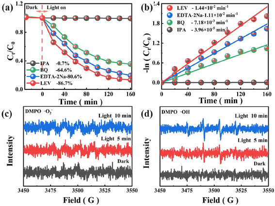 | ||
| Fig. 6 (a) LEV degradation efficiency and (b) reaction kinetics with various scavengers; the EPR spectra of (c) ˙O2− and (d) ˙OH. | ||
EPR tests were conducted to further confirm the existence of ˙O2− and OH active species with DMPO as the spin trap, the existence of visible light was the only difference.28,40 EPR spectrum tests in the dark reveal no obvious signal. Fig. 6(c) appeared a 1![[thin space (1/6-em)]](https://www.rsc.org/images/entities/char_2009.gif) :
:![[thin space (1/6-em)]](https://www.rsc.org/images/entities/char_2009.gif) 2
2![[thin space (1/6-em)]](https://www.rsc.org/images/entities/char_2009.gif) :
:![[thin space (1/6-em)]](https://www.rsc.org/images/entities/char_2009.gif) 2
2![[thin space (1/6-em)]](https://www.rsc.org/images/entities/char_2009.gif) :
:![[thin space (1/6-em)]](https://www.rsc.org/images/entities/char_2009.gif) 1 signal of DMPO–˙OH, when the ˙OH was captured by DMPO, which further confirmed the presence of ˙OH. Similarly, the four signals of 1
1 signal of DMPO–˙OH, when the ˙OH was captured by DMPO, which further confirmed the presence of ˙OH. Similarly, the four signals of 1![[thin space (1/6-em)]](https://www.rsc.org/images/entities/char_2009.gif) :
:![[thin space (1/6-em)]](https://www.rsc.org/images/entities/char_2009.gif) 1
1![[thin space (1/6-em)]](https://www.rsc.org/images/entities/char_2009.gif) :
:![[thin space (1/6-em)]](https://www.rsc.org/images/entities/char_2009.gif) 1
1![[thin space (1/6-em)]](https://www.rsc.org/images/entities/char_2009.gif) :
:![[thin space (1/6-em)]](https://www.rsc.org/images/entities/char_2009.gif) 1 were detected in Fig. 6(d), but the peak of DMPO–˙O2− intensity was weak, which indicated that a few ˙O2− can be generated.29,35 Above all, ˙OH and ˙O2− are recognized the domain reactive species in this system.
1 were detected in Fig. 6(d), but the peak of DMPO–˙O2− intensity was weak, which indicated that a few ˙O2− can be generated.29,35 Above all, ˙OH and ˙O2− are recognized the domain reactive species in this system.
3.5. Proposed degradation pathways
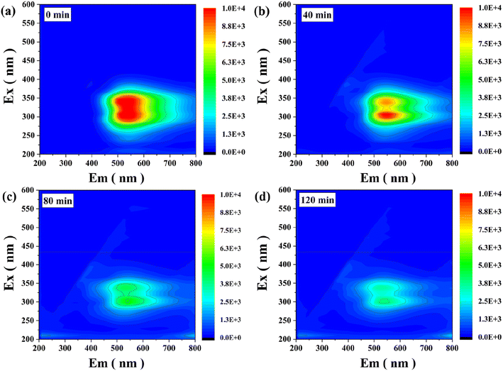
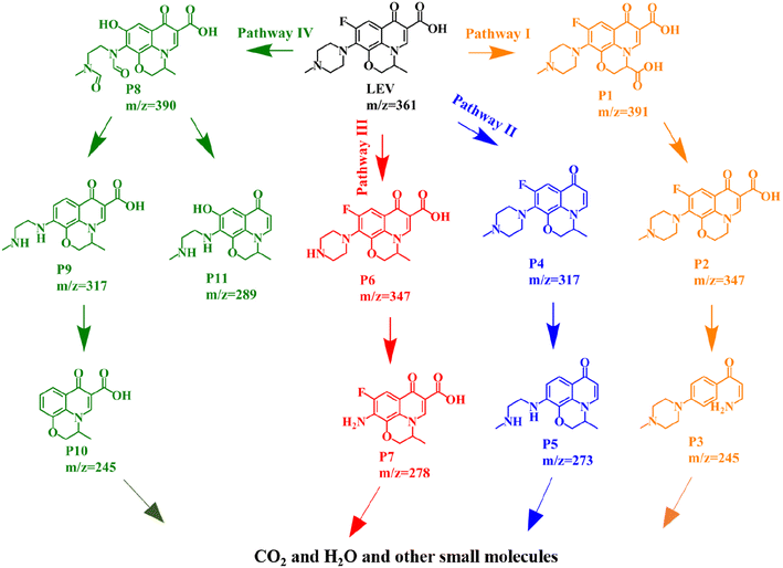
The obtained 3D EEMs spectra provide important information on the fluorescence changes during LEV degradation.21,50 Here, Ex represents the emission wavelength (nm) and Em represents the excitation wavelength (nm). As shown in Fig. 7(a), two obvious humus acid-like peaks located at Ex/Em = (320–360/450–600) nm and Ex/Em = (270–320/400–450) nm. The intensity of fluorescence peaks obviously decreased when extending the reaction time to 40 min, implying that the conjugated heterocycle structure of LEV was destroyed (Fig. 7(b)). Moreover, the intensity of the fluorescence peaks continued to decrease with the increase of illumination time (Fig. 7(c)). After 120 min of light illumination (Fig. 7(d)), there is almost no obvious fluorescence signal, exhibiting that the intermediate products of LEV are decomposed into small molecules and eventually mineralized to H2O and CO2.The intermediates and potential degradation pathways of LEV degradation by SIT were identified by LC-MS.4,47 The obtained mass spectra and intermediates were depicted in Fig. S5–S6 and Table S1,† respectively. Based on previous similar reports, four possible degradation pathways of LEV were proposed, as shown in Fig. 8. In pathway I, the product P1 (m/z = 391) was formed by carboxylation. Then, the intermediates passed through decarboxylation to degrade to P2 (m/z = 374).44 After the oxazine ring being destroyed, the production of P3 (m/z = 245) from P2 was attributed to the defluorination and decarboxylation.3 As for pathway II, LEV undergoes decarboxylation to form the P4 (m/z = 317).27 P4 was further reduced and removed by fluorination to produce P5 (m/z = 273).40 Further, take off the piperazine ring to obtain P7 (m/z = 278).46 Pathway IV, P8 (m/z = 390) was produced by changing fluorine group into hydroxyl group while opening and oxidizing piperazine ring.4 Next, P9 (m/z = 317) was generated by the cleavage of the hydroxyl group and demethylation to obtain product P10 (m/z = 245).20 Simultaneous, the production of P11 (m/z = 289) from P8 were attributed to the removal of C![[double bond, length as m-dash]](https://www.rsc.org/images/entities/char_e001.gif) O bond and decarboxylation.51 Finally, the intermediates might be further generated to CO2, H2O and other small molecules.
O bond and decarboxylation.51 Finally, the intermediates might be further generated to CO2, H2O and other small molecules.
Meanwhile, Fig. S7(a)† presents the changes of total organic carbon (TOC) during the degradation process of LEV. After 160 min of light irradiation, TOC removal rate of LEV by the SIT reaches 68.5%. The result further indicates that the structure of LEV is indeed broken and decomposed into H2O and CO2 as well as some intermediate products during the process of photocatalytic degradation. Thus, it shows that SIT has good degradability as well as mineralization ability towards LEV.
3.6. Optics and photoelectrochemical investigations
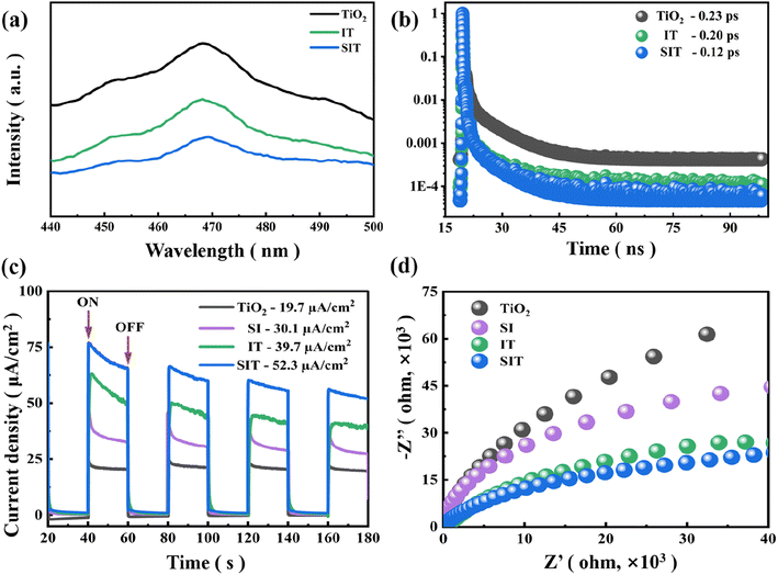
Relevant research shows that the higher the PL intensity, the higher the electron–hole recombination rate and the weaker the photocatalytic performance.6 PL spectra of TiO2, IT and SIT were shown in Fig. 9(a), the samples exhibited a strong emission peak centered at 467 nm, the PL intensity of SIT as comparison to TiO2 and IT was weaker, which indicates that it has high efficiency of photogenerated electron–hole separation.45 In addition, the charge separation kinetics of the samples were investigated via time-resolved photoluminescence (TRPL) spectroscopy. In Fig. 9(b), the lifetime (τ) of TiO2, IT and SIT were 0.23 ps, 0.20 ps and 0.12 ps, respectively. This result confirms that SIT had the shortest electron lifetime, suggesting the fastest charge transfer of electrons across electrode/electrolyte interface in SIT photoanode.24 The ability of photogenerated carriers to separate and migrate can be easily observed in the photocurrent density curve.19 Fig. 9(c) exhibits the transient photocurrent under visible light with light on–off cycles, the photocurrent response density of SIT (52.3 A cm−2) showed the higher current density than that of IT (39.7 μA cm−2), SI (30.1 μA cm−2) and TiO2 (19.7 μA cm−2). When the lamp was turned off, the current quickly decreased to the initial value. As reported, the radius of semicircle arc represents the charge transfer resistance.45 As shown in Fig. 9(d), the EIS spectra display that the arc radius of SIT was smallest than those of IT, SI and TiO2, indicating the lowest electrical impedance and the highest carrier transfer efficiency.253.7. Photocatalytic mechanism
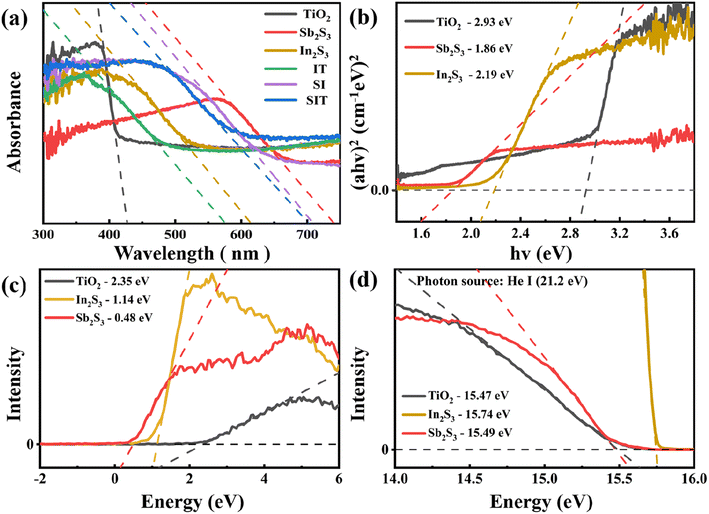
The UV-vis DRS absorption spectrum of the prepared material was used to investigate the photo-absorption was shown in Fig. 6(a). IT similar to In2S3 shows a photo-absorption edge at 577 nm, which was also improved due to the presence of TiO2. SI is similar to Sb2S3 and shows a light absorption edge at 709 nm. In addition, after modifying Sb2S3 on IT. The photo-absorption of SIT has been broadened (edge: 654 nm) compared with that of IT. The optical band gap was calculated using linear extrapolation of the Tauc plot based on the Kubelka–Munk function (eqn (S1)†), as shown in Fig. 10(b).25 The band gap values for TiO2, In2S3, and Sb2S3 were estimated to be about 2.93, 2.19, and 1.86 eV.According to the results of XPS valence band (VB) spectra (Fig. 10(c)), the VB of TiO2, In2S3, and Sb2S3 are 2.35 eV, 1.14 eV, and 0.48 eV, respectively. The UPS spectra with cutoff energy (Ecutoff) at high binding energy are shown in Fig. 10(c). When Fermi levels (EF) are consistent with 0 eV, the corresponding Ecutoff of TiO2, In2S3 and Sb2S3 are 15.47 eV, 15.74 eV and 15.49 eV, respectively.36 Therefore, as calculated by eqn (S4),† the work functions of TiO2, In2S3, and Sb2S3 are 2.35 eV, 1.14 eV, and 0.48 eV, respectively.
Because of the contact potential difference between the sample and the XPS analyzer, the VB location of the sample with respect to the general hydrogen electrode (NHE) can be estimated using the formula in eqn (1):36
| EVB = EVB–XPS + φ − 4.44 | (1) |
| ECB = Eg − EVB | (2) |
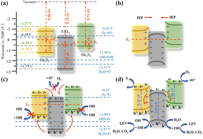
Two potential charge transfer modes type II heterojunction and Z-type heterojunction – are suggested for SIT photocatalytic degradation of LEV based on the results from the previous analysis (Fig. 11).33 Together with Fig. 11(c), photogenerated holes will go from the VB of TiO2 to the VB of In2S3 and Sb2S3, whereas photogenerated electrons will move from the CB of In2S3 and Sb2S3 to the CB of TiO2. The electrons in the CB of TiO2 are unable to decrease O2/˙O2− because the CB potential of TiO2 (−0.18 V vs. NHE) is more positive than the typical superoxide radical potential O2/˙O2− (−0.33 V vs. NHE).17 Additionally, the In2S3 and Sb2S3 cavities in VB do not have enough oxidation capacity to make ˙OH since the VB of In2S3 and Sb2S3 (+1.25 and +0.59 V vs. NHE, respectively) is more negative than the usual redox potentials H2O/˙OH (+2.37 V vs. NHE) and OH−/˙OH (+1.99 V vs. NHE).18 If the SIT interface is a conventional type II heterojunction, then there should be no signal for ˙OH and ˙O2−. However, signals for ˙OH, ˙O2− and h+ were observed in radical trapping experiments and EPR spectroscopy; therefore, the charge transfer in SIT is not a type II heterojunction.
The reaction mechanism for the degradation of LEV by the SIT dual Z-type heterojunction suggested in this research is shown in Fig. 11(d) based on the data mentioned above. As shown in Fig. 11(a), the Fermi energy levels (EF) of In2S3 and Sb2S3 are higher than those of TiO2 prior to contact. When Sb2S3/In2S3/TiO2 are successfully compounded, a heterojunction is formed between them and electrons migrate from the In2S3 and Sb2S3 interfaces to TiO2 until the EF of the three semiconductors reach equilibrium. The electron transfer paths are consistent with those determined using high-resolution XPS. At the same time, an internal electric field (IEF) was formed in the interface region and pointed from In2S3 and Sb2S3 to TiO2. Thereafter, photogenerated electrons migrated from TiO2 to In2S3 and Sb2S3 under light irradiation driven by the IEF (Fig. 11(b)). Notably, IEF was present, which supported the results of photoelectrochemical tests by facilitating electron transfer and strongly hindered the complexation of photogenerated carriers.23 Furthermore, the IEF increased the electronic potential energy of In2S3 and Sb2S3 and decreased that of TiO2, resulting in the energy band edges of In2S3 and Sb2S3 showing an upward band bend and that of TiO2 showing a downward band bend (Fig. 11(b)). Energy band variations are a prominent feature of Z-scheme heterojunctions, a charge transport pathway that greatly increases separation rates and reduces recombination of photogenerated electron–hole pairs.
Electrons in TiO2, In2S3, and Sb2S3 are stimulated by photons when exposed to visible light (eqn (3)–(5)).25 With the help of IEF, electrons in the CB of TiO2 bind to holes in the VB of In2S3 and Sb2S3 (eqn (6) and (7)),45 isolating the holes of TiO2 and the electrons of In2S3 and Sb2S3 to the greatest extent possible. Additionally, the superoxide radical potential of O2/˙O2− is less negative than the CB energy levels of In2S3 and Sb2S3, allowing the electrons in In2S3 and Sb2S3 with high reducing capacity to convert adsorbed O2 to ˙O2− (eqn (8) and (9)).22 After that, some of the ˙O2− reacts with the H+ to create H2O2 (eqn (10) and (11)).19 H2O2 then undergoes a second reaction with ˙O2− to produce OH (eqn (12)).36 The strongly oxidizing h+ in TiO2 can oxidize H2O and OH− to generate ˙OH since the VB level of TiO2 is higher than the usual redox potentials of H2O/˙OH and OH−/˙OH. Also, the holes left on TiO2 can directly capture the electrons in LEV molecules and oxidize them directly. Therefore, the degradation of LEVs in SIT systems is dominated by radicals such as ˙OH, ˙O2− and h+ (eqn (15)).24 As a result, the charge transfer in SIT is a Z-type heterojunction, and the successful construction of the Z-type heterojunction enables the efficient separation and transfer of photogenerated electrons and holes of the three semiconductors, while the strongly oxidizing holes are retained in the CB of TiO2 and the strongly reducing electrons are retained in the VB of In2S3 and Sb2S3. As a result, the SIT system successfully degrades LEV by photocatalysis. The possible reaction steps are shown in eq:
| TiO2 + hν = TiO2 (e− + h+) | (3) |
| In2S3 + hν = In2S3 (e− + h+) | (4) |
| Sb2S3 + hν = Sb2S3 (e− + h+) | (5) |
| TiO2 (e−) + In2S3 (h+) → TiO2 + In2S3 | (6) |
| TiO2 (e−) + Sb2S3 (h+) → TiO2 + Sb2S3 | (7) |
| In2S3 (e−) + (O2)abs → In2S3 + ˙O2− | (8) |
| Sb2S3 (e−) + (O2)abs → Sb2S3 + ˙O2− | (9) |
| ˙O2− + H+ = ˙OOH | (10) |
| H2O2 + ˙O2− = ˙OH + OH− + O2 | (11) |
| ˙OOH + ˙OOH = H2O2 | (12) |
| TiO2 (h+) + H2O → TiO2 + ˙OH + H+ | (13) |
| TiO2 (h+) + OH− → TiO2 + ˙OH | (14) |
| ˙OH/˙O2−/h+ + LEV = CO2 + HO2 + small molecules | (15) |
4. Conclusion
In this study, Z-type Sb2S3/In2S3/TiO2 (SIT) heterojunction photocatalysts were constructed by anchoring In2S3 nanosheets and Sb2S3 nanoparticles to form a layered structure on TiO2 nanorod arrays using a simple two-step hydrothermal method. The morphology and structure of the SIT photocatalysts were accurately described using XRD, SEM, TEM and XPS. Under visible light, the Z-type SIT catalyst exhibited excellent photocatalytic activity in the degradation of levofloxacin (LEV) with a high degradation efficiency of 86.7%. The kinetic rate was 1.44 × 10⁻² min−1, which was 2.36 and 1.25 times higher than that of TiO2 and In2S3/TiO2 (IT) composites, respectively. Under the same experimental conditions, the SIT photocatalytic system also exhibited excellent photocatalytic degradation activities for CHI, GAT and AMP, with degradation efficiencies of 81.2%, 67.0% and 28.8%, respectively, which indicated that the material has a wide range of applicability to antibiotics. Meanwhile, the main oxidising radicals in the photocatalytic system were identified as ˙O2− and ˙OH by capture experiments and electron spin resonance spectroscopy (EPR), and the degradation pathways and intermediates of LEVs were revealed by liquid chromatography mass spectrometry (LC-MS) and three-dimensional excitation–emission matrix fluorescence (3D EEMs). In addition, PL, TRPL, UV-visible and photoelectrochemical property tests were carried out, which demonstrated the excellent full-spectrum responsiveness and charge separation and transfer ability of SIT, formulated the energy band structure of the Z-type heterojunction, and proposed the degradation steps and mechanism of the Z-type SIT photocatalyst. Overall, this study provides novel insights into the degradation of antibiotics using thin-film photocatalysts.Author contributions
Jianrou Li: investigation, writing-original draft. Zhuangzhuang Yin: investigation, formal analysis. Jun Guo: visualization, formal analysis. Wei Gan: visualization, software. Ruixin Chen: investigation, visualization. Miao Zhang: formal analysis. Zhaoqi Sun: funding acquisition.Conflicts of interest
There are no conflicts to declare.Acknowledgements
This study is supported by the National Natural Science Foundation of China (No. 51772003, 51472003 and 51701001). The authors are also grateful to Huimin Fang, Jun Zheng, Zhongqing Lin, Xiuzhen Zhang and Shenqiang Zhao of the Experimental Technology Center for providing support with the microstructure characterization. The authors also like to thank Lei He from Shiyanjia Lab (https://www.shiyanjia.com) for the Electron Paramagnetic Resonance (EPR) analysis.Notes and references
- L. He, S. Yang, S. Shen, Y. Ma, Y. Chen, J. Xue, J. Wang, L. Zheng, L. Wu, Z. Zhang and L. Yang, Novel insights into the mechanism of periodate activation by heterogeneous ultrasonic-enhanced sludge biochar: Relevance for efficient degradation of levofloxacin, J. Hazard. Mater., 2022, 434, 128860 CrossRef CAS PubMed.
- Q. Y. Jin, D. Y. Ji, Y. H. Chen, Z. M. Tang and Y. S. Fu, Kinetics and pathway of levofloxacin degradation by ferrate(VI) and reaction mechanism of catalytic degradation by copper sulfide, Sep. Purif. Technol., 2022, 282, 120104 CrossRef CAS.
- J. Cai, Y. Zhang, T. Qian, X. Li, Z. Chen and L. Zhang, Bismuth oxybromide/bismuth oxyiodide nanojunctions decorated on flexible carbon fiber cloth as easily recyclable photocatalyst for removing various pollutants from wastewater, J. Colloid Interface Sci., 2022, 608, 2660–2671 CrossRef CAS PubMed.
- Q. C. Deng, X. D. Zhang, L. Chang, H. X. Chai and Y. M. Huang, The MOF/LDH derived heterostructured Co3O4/MnCo2O4 composite for enhanced degradation of levofloxacin by peroxymonosulfate activation, Sep. Purif. Technol., 2022, 294, 121182 CrossRef CAS.
- Y. Zhao, H. Guo, J. Liu, Q. Xia, J. Liu, X. Liang, E. Liu and J. Fan, Effective photodegradation of rhodamine B and levofloxacin over CQDs modified BiOCl and BiOBr composite: Mechanism and toxicity assessment, J. Colloid Interface Sci., 2022, 627, 180–193 CrossRef CAS PubMed.
- Z. Fang, Z. Zhou, G. Xue, Y. Yu, Q. Wang, B. Cheng, Y. Ge and Y. Qian, Application of sludge biochar combined with peroxydisulfate to degrade fluoroquinolones: Efficiency, mechanisms and implication for ISCO, J. Hazard. Mater., 2022, 426, 128081 CrossRef CAS PubMed.
- C. K. Tsai, Y. C. Lee, T. T. Nguyen and J. J. Horng, Levofloxacin degradation under visible-LED photo-catalyzing by a novel ternary Fe-ZnO/WO3 nanocomposite, Chemosphere, 2022, 298, 134285 CrossRef CAS PubMed.
- J. K. Nie, X. J. Yu, Z. B. Liu, Y. C. Wei, J. Zhang, N. N. Zhao, Z. Yu and B. H. Yao, Boosting principles for the photocatalytic performance of Cr-doped CuO crystallites and mechanisms of photocatalytic oxidation for levofloxacin, Appl. Surf. Sci., 2022, 576, 151842 CrossRef CAS.
- T. Qian, Y. Zhang, J. Cai, W. Cao, T. Liu, Z. Chen, J. Liu, F. Li and L. Zhang, Decoration of amine functionalized zirconium metal organic framework/silver iodide heterojunction on carbon fiber cloth as a filter- membrane-shaped photocatalyst for degrading antibiotics, J. Colloid Interface Sci., 2021, 603, 582–593 CrossRef CAS PubMed.
- Z. R. Deng, X. Y. Zheng and Y. F. Guo, Effective degradation of doxycycline hydrochloride in simulated and real water by S-scheme heterojunction 2D/1D Bi4O5I2/In2O3 under visible light: DFT calculation, mechanism, degradation pathway and toxicity analysis, Appl. Surf. Sci., 2023, 641, 158407 CrossRef CAS.
- Z. Deng, Y. Li, X. Zheng and Y. Guo, Photocatalytic activity evaluation of polyvinylpyrrolidone K30 assisted synthesis of 1D oxygen-vacancy-rich Bi5O7BrxI1-x nanorod solid solution, J. Hazard. Mater., 2024, 465, 133361 CrossRef CAS PubMed.
- J. J. Cheng, Z. R. Deng, X. Y. Zheng, C. Y. Chu and Y. F. Guo, Construction and actual application of In2O3/BiOBr heterojunction for effective removal of ciprofloxacin under visible light: Photocatalytic mechanism, DFT calculation,degradation pathway and toxicity evaluation, J. Alloys Compd., 2024, 971, 172779 CrossRef CAS.
- Z. Zeng, Z. R. Deng, T. Wang, H. S. Huang and Y. F. Guo, Environmentally friendly synthesis of S-scheme heterojunction UiO-66-NH2/Bi7O9I3 for promoted degradation of ciprofloxacin under visible light: DFT calculation, degradation mechanism and toxicity evaluation, Sep. Purif. Technol., 2023, 311, 123264 CrossRef CAS.
- Y. Liang, G. Huang, X. Xin, Y. Yao, Y. Li, J. Yin, X. Li, Y. Wu and S. Gao, Black titanium dioxide nanomaterials for photocatalytic removal of pollutants: A review, J. Mater. Sci. Technol., 2022, 112, 239–262 CrossRef CAS.
- L. Wang, X. Fei, L. Zhang, J. Yu, B. Cheng and Y. Ma, Solar fuel generation over nature-inspired recyclable TiO2/g-C3N4 S-scheme hierarchical thin-film photocatalyst, J. Mater. Sci. Technol., 2022, 112, 1–10 CrossRef CAS.
- S. Zhang, S. Sun, B. Huang, N. Wang and X. Li, UV-Enhanced Formaldehyde Sensor Using Hollow In2O3@TiO2 Double-Layer Nanospheres at Room Temperature, ACS Appl. Mater. Interfaces, 2023, 15, 4329–4342 CrossRef CAS PubMed.
- C. Hu, L. Chen, Y. Hu, A. Chen, L. Chen, H. Jiang and C. Li, Light-Motivated SnO2/TiO2 Heterojunctions Enabling the Breakthrough in Energy Density for Lithium-Ion Batteries, Adv. Mater., 2021, 33, 2103558 CrossRef CAS PubMed.
- L. Wang, B. Cheng, L. Zhang and J. Yu, In situ Irradiated XPS Investigation on S-Scheme TiO2@ZnIn2S4 Photocatalyst for Efficient Photocatalytic CO2 Reduction, Small, 2021, 17, 2103447 CrossRef CAS PubMed.
- W. Gan, X. C. Fu, J. Guo, M. Zhang, H. Yu, C. S. Ding, S. A. Qi, X. Y. Cao and Z. Q. Sun, Facile synthesis of mesoporous hierarchical TiO2 micro-flowers serving as the scaffolding of 0D Ag3PO4 nanoparticles for the ultra-fast degradation of organic pollutants, J. Alloys Compd., 2022, 909, 164737 CrossRef CAS.
- Z. T. Dong, C. G. Niu, H. Guo, H. Y. Niu, S. Liang, C. Liang, H. Y. Liu and Y. Y. Yang, Anchoring CuFe2O4 nanoparticles into N-doped carbon nanosheets for peroxymonosulfate activation: Built-in electric field dominated radical and non-radical process, Chem. Eng. J., 2021, 426, 130850 CrossRef CAS.
- Z. Pang, P. Luo, C. Wei, Z. Qin, T. Wei, Y. Hu, H. Wu and C. Wei, In-situ growth of Co/Ni bimetallic organic frameworks on carbon spheres with catalytic ozonation performance for removal of bio-treated coking wastewater, Chemosphere, 2022, 291, 132874 CrossRef CAS PubMed.
- W. Gan, X. Fu, J. Jin, J. Guo, M. Zhang, R. Chen, C. Ding, Y. Lu, J. Li and Z. Sun, Nitrogen-rich carbon nitride (C3N5) coupled with oxygen vacancy TiO2 arrays for efficient photocatalytic H2O2 production, J. Colloid Interface Sci., 2024, 653, 1028–1039 CrossRef CAS PubMed.
- Y. Tao, Z. Ma, W. C. Wang, C. Zhang, L. L. Fu, Q. Zhu, Y. L. Li, G. S. Li and D. Q. Zhang, Nickel Phosphide Clusters Sensitized TiO2 Nanotube Arrays as Highly Efficient Photoanode for Photoelectrocatalytic Urea Oxidation, Adv. Funct. Mater., 2023, 33, 2211169 CrossRef CAS.
- W. Gan, X. C. Fu, J. Guo, M. Zhang, D. D. Li, C. S. Ding, Y. Q. Lu, P. Wang and Z. Q. Sun, Ag nanoparticles decorated 2D/2D TiO2/g-C3N4 heterojunction for efficient removal of tetracycline hydrochloride: Synthesis, degradation pathways, and mechanism, Appl. Surf. Sci., 2022, 606, 154837 CrossRef CAS.
- J. Guo, W. Gan, C. S. Ding, Y. Q. Lu, J. R. Li, S. H. Qi, M. Zhang and Z. Q. Sun, Black phosphorus quantum dots and Ag nanoparticles co-modified TiO2 nanorod arrays as powerful photocatalyst for tetracycline hydrochloride degradation: Pathways, toxicity assessment, and mechanism insight, Sep. Purif. Technol., 2022, 297, 1383–5866 CrossRef.
- J. Jiang, X. Wang, C. Yue, S. Liu, Y. Lin, T. Xie and S. Dong, Efficient photoactivation of peroxymonosulfate by Z-scheme nitrogen-defect-rich NiCo2O4/g-C3N4 for rapid emerging pollutants degradation, J. Hazard. Mater., 2021, 414, 125528 CrossRef CAS PubMed.
- F. Z. Chen, Y. J. Li, M. Zhou, X. X. Gong, Y. Gao, G. Cheng, S. B. Ren and D. M. Han, Smart multifunctional direct Z-scheme In2S3@PCN-224 heterojunction for simultaneous detection and photodegradation towards antibiotic pollutants, Appl. Catal., B, 2023, 328, 122517 CrossRef CAS.
- B. Geng, S. Zhang, X. Yang, W. Shi, P. Li, D. Pan and L. Shen, Cu2-xO@TiO2-y Z-type heterojunctions for sonodynamic-chemodynamic combined tumor eradication, Chem. Eng. J., 2022, 435, 134777 CrossRef CAS.
- X. Zheng, T. Liu, J. Wen and X. Liu, Flower-like Bi2S3-In2S3 heterojunction for efficient solar light induced photoreduction of Cr(VI), Chemosphere, 2021, 278, 130422 CrossRef CAS PubMed.
- J. Park, T. H. Lee, C. Kim, S. A. Lee, M. J. Choi, H. Kim, J. W. Yang, J. Lim and H. W. Jang, Hydrothermally obtained type-II heterojunction nanostructures of In2S3/TiO2 for remarkably enhanced photoelectrochemical water splitting, Appl. Catal., B, 2021, 295, 120276 CrossRef CAS.
- C. Z. Zhu, H. Q. Yao, S. K. Le, Y. Yin, C. X. Chen, H. T. Xu, S. B. Wang and X. G. Duan, S-scheme photocatalysis induced by ultrathin TiO2(B) nanosheets-anchored hierarchical In2S3 spheres for boosted photocatalytic activity, Composites, Part B, 2022, 242, 110082 CrossRef CAS.
- Y. Xiao, H. Wang, Y. Jiang, W. Zhang, J. Zhang, X. Wu, Z. Liu and W. Deng, Hierarchical Sb2S3/ZnIn2S4 core-shell heterostructure for highly efficient photocatalytic hydrogen production and pollutant degradation, J. Colloid Interface Sci., 2022, 623, 109–123 CrossRef CAS PubMed.
- Z. Y. Zhu, J. Y. Li, W. Li, X. Y. Liu, Y. Y. Dang, T. H. Ma and C. Y. Wang, Simulated-sunlight-driven Cr(VI) reduction on a type-II heterostructured Sb2S3/CdS photocatalyst, Environ. Sci.: Nano, 2022, 9, 1738–1747 RSC.
- J. Zhao, Y. Cheng, Y. Chen, W. Zhang, E. Liu, J. Fan, H. Miao and X. Hu, Defects regulation of Sb2S3 by construction of Sb2S3/In2S3 direct Z-type heterojunction with enhanced photoelectrochemical performance, Appl. Surf. Sci., 2021, 568, 150917 CrossRef CAS.
- K. W. Wang, Z. P. Huang and J. Wang, Synthesis of hierarchical tandem double Z-scheme heterojunctions for robust photocatalytic H2 generation, Chem. Eng. J., 2022, 430, 132727 CrossRef CAS.
- C. S. Ding, Y. Q. Lu, J. Guo, W. Gan, S. H. Qi, Z. Z. Yin, M. Zhang and Z. Q. Sun, Internal electric field-mediated sulfur vacancies-modified-In2S3/TiO2 thin-film heterojunctions as a photocatalyst for peroxymonosulfate activation: Density functional theory calculations, levofloxacin hydrochloride degradation pathways and toxicity of intermediates, Chem. Eng. J., 2022, 450, 138271 CrossRef CAS.
- S. Sharma and S. Basu, Fabrication of centimeter-sized Sb2S3/SiO2 monolithic mimosa pudica nanoflowers for remediation of hazardous pollutants from industrial wastewater, J. Cleaner Prod., 2021, 280, 124525 CrossRef CAS.
- M. L. Tang, Y. H. Ao, C. Wang and P. F. Wang, Rationally constructing of a novel dual Z-scheme composite photocatalyst with significantly enhanced performance for neonicotinoid degradation under visible light irradiation, Appl. Catal., B, 2020, 270, 118918 CrossRef CAS.
- T. Garg, Renu, J. Kaur, P. Kaur, Nitansh, V. Kumar, K. Tikoo, A. Kaushik and S. Singhal, An innovative Z-type g-C3N4/ZnO/NiFe2O4 heterostructure for the concomitant photocatalytic removal and real-time monitoring of noxious fluoroquinolones, Chem. Eng. J., 2022, 443, 136441 CrossRef CAS.
- X. Chen, R. T. Guo, W. G. Pan, Y. Yuan, X. Hu, Z. X. Bi and J. Wang, A novel double S-scheme photocatalyst Bi7O9I3/Cd0.5Zn0.5S QDs/WO3−x with efficient full-spectrum-induced phenol photodegradation, Appl. Catal., B, 2022, 318, 121839 CrossRef CAS.
- H. Sepehrmansourie, H. Alamgholiloo, N. N. Pesyan and M. A. Zolfigol, A MOF-on-MOF strategy to construct double Z-scheme heterojunction for high-performance photocatalytic degradation, Appl. Catal., B, 2023, 321, 122082 CrossRef CAS.
- M. L. Ren, Y. H. Ao, P. F. Wang and C. Wang, Construction of silver/graphitic-C3N4/bismuth tantalate Z-scheme photocatalyst with enhanced visible-light-driven performance for sulfamethoxazole degradation, Chem. Eng. J., 2019, 378, 122122 CrossRef CAS.
- Y. Guo, Y. H. Ao, P. F. Wang and C. Wang, Mediator-free direct dual-Z-scheme Bi2S3/BiVO4/MgIn2S4 composite photocatalysts with enhanced visible-light-driven performance towards carbamazepine degradation, Appl. Catal., B, 2019, 254, 479–490 CrossRef CAS.
- S. S. M. Bhat, S. A. Pawar, D. Potphode, C.-K. Moon, J. M. Suh, C. Kim, S. Choi, D. S. Patil, J.-J. Kim, J. C. Shin and H. W. Jang, Substantially enhanced photoelectrochemical performance of TiO2 nanorods/CdS nanocrystals heterojunction photoanode decorated with MoS2 nanosheets, Appl. Catal., B, 2019, 259, 118102 CrossRef CAS.
- S. A. Qi, Z. Z. Yin, Z. Liu, K. Xu, M. Zhang and Z. Q. Sun, Construction of In2S3/Ag-Ag2S-AgInS2/TNR Nanoarrays with Excellent Photoelectrochemical and Photocatalytic Properties, J. Electrochem. Soc., 2021, 168, 126517 CrossRef CAS.
- Y. Chen, Y. Cheng, J. Zhao, W. Zhang, J. Gao, H. Miao and X. Hu, Construction of Sb2S3/CdS/CdIn2S4 cascaded S-scheme heterojunction for improving photoelectrochemical performance, J. Colloid Interface Sci., 2022, 627, 1047–1060 CrossRef CAS PubMed.
- J. Shen, L. Qian, J. Huang, Y. Guo and Z. Zhang, Enhanced degradation toward Levofloxacin under visible light with S-scheme heterojunction In2O3/Ag2CO3: Internal electric field, DFT calculation and degradation mechanism, Sep. Purif. Technol., 2021, 275, 119239 CrossRef CAS.
- J. M. Li, C. C. Wu, J. Li, B. H. Dong, L. Zhao and S. M. Wang, 1D/2D TiO2/ZnIn2S4 S-scheme heterojunction photocatalyst for efficient hydrogen evolution, Chin. J. Catal., 2022, 43, 339–349 CrossRef CAS.
- L. Chen, X. L. Song, J. T. Ren and Z. Y. Yuan, Precisely modifying Co2P/black TiO2 S-scheme heterojunction by in situ formed P and C dopants for enhanced photocatalytic H2 production, Appl. Catal., B, 2022, 315, 121546 CrossRef CAS.
- J. Shen, L. Qian, J. Huang, Y. Guo and Z. Zhang, Enhanced degradation toward Levofloxacin under visible light with S-scheme heterojunction In2O3/Ag2CO3: Internal electric field, DFT calculation and degradation mechanism, Sep. Purif. Technol., 2021, 275, 119239 CrossRef CAS.
- M. H. Elbakkay, W. M. A. El Rouby, A. Mariño-López, A. Sousa-Castillo, V. Salgueiriño, S. I. El-Dek, A. A. Farghali, M. A. Correa-Duarte and P. Millet, One-pot synthesis of TiO2/Sb2S3/RGO complex multicomponent heterostructures for highly enhanced photoelectrochemical water splitting, Int. J. Hydrogen Energy, 2021, 46, 31216–31227 CrossRef CAS.
Footnote |
| † Electronic supplementary information (ESI) available. See DOI: https://doi.org/10.1039/d3ra08905c |
| This journal is © The Royal Society of Chemistry 2024 |


