 Open Access Article
Progress of research on the bonding-strength improvement of two-layer adhesive-free flexible copper-clad laminates
Wanqi Tangab,
Yuxi Liu *b,
Xianghai Jingb,
Jinsong Houb,
Qianfeng Zhanga and
Chongguang Jianc
aInstitute of Molecular Engineering and Applied Chemistry, Anhui University of Technology, Ma'anshan 243002, China
bCollege of Materials and Chemical Engineering, Chuzhou University, Chuzhou 239000, China. E-mail: liuyuxiemail@126.com
cChuzhou HKC Optoelectronics Co., Ltd, Chuzhou 239000, China
First published on 17th April 2024
Abstract
The arrival of the 5G era has placed high demands on the electronic products. Developing thin, light, and portable electronic products capable of simultaneously improving the transmission rate and reducing the signal delay and transmission loss is necessary to meet such demands. The traditional three-layer, adhesive, flexible copper-clad laminate (3L-FCCL) cannot satisfy these demands because of its adhesive component. The large thickness and poor heat resistance disadvantages of 3L-FCCL can be avoided with a two-layer, adhesive-free, flexible copper-clad laminate (2L-FCCL). However, 2L-FCCL has low bonding strength. This work introduces the selection of conductor materials and insulating base films for flexible copper-clad laminates. Modification studies aimed at increasing the bonding performance of 2L-FCCL are summarized based on three aspects. These modification techniques include the surface treatment of copper foils, modification and surface treatment of polyimide films, and surface treatment of liquid-crystal polymers. Prospects are further provided.
1 Introduction
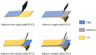
The arrival of the 5G era places a growing demand for high data rates and high-quality service in communication technology, especially for printed circuit boards (PCBs).1 According to their structural strength, PCBs can be categorized into rigid boards, flexible boards, and rigid–flexible combination. Flexible copper-clad laminate (FCCL) is a flexible board and a special type of electronic interconnect base material.2–4 The thinness, lightness, bendability, and 3D assembly of FCCLs enable their extensive use in foldable electronic devices (e.g., foldable cell phones and laptops), artificial intelligence (e.g., bionic micro-robots), medical devices, aerospace, and other fields.Driven by the introduction of polyimide (PI) film, U.S. engineers prepared the first generation of FCCL in the 1960s by continuously improving the lamination process to press the film, resin, and copper foil together.5 With the development of the electronics industry, the demand for FCCL has grown. FCCLs can be divided into several categories according to the substrates, applications, sizes, and properties, and these major categories can be subdivided into subcategories. The product structure is usually categorized into a three-layer adhesive type (3L-FCCL) and a two-layer non-adhesive type (2L-FCCL) (Fig. 1).
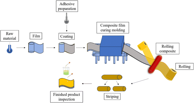
The preparation methods of 3L-FCCL mainly include sheet manufacturing and roll manufacturing. The prepared adhesive is evenly coated on the film and pressed together with copper foil after drying and curing. Coil manufacturing has the advantages of high production efficiency, stable product quality, and high raw material utilization and is often used in 3L-FCCL industrial production. Fig. 2 provides a simple process flow of roller pressing for 3L-FCCL preparation.
Currently, there are three preparation methods commonly used for 2L-FCCL.
(1) Coating method. The substrate is coated with one or more layers of functional materials to imbue it with special functions or improve its surface properties. This method is mostly used to prepare single-sided copper-clad plates. Coating methods are categorized according to their metering technique as follows: estimated amount coating, concave plate coating, self-metering coating, and metering modification coating. The broad category also contains subcategories. For example, lip seam extrusion coating is a predicted coating method applied in 2L-FCCL industrial production. During coating, the solution is injected into the extruder nozzle, the substrate moves on the back roller at a set speed, and the solution is coated on the copper foil through the lip seam coating head to form a single-sided wet film with uniform thickness. After baking, a single-sided FCCL is finally obtained. During laboratory preparation (taking liquid-crystal polymer (LCP)-FCCL preparation as an example), the LCP solution is coated on copper foil, baked to remove most of the solvent, and then heated to bake under nitrogen atmosphere to obtain a single-sided LCP-FCCL.
(2) Lamination method. This process is similar to the preparation of 3L-FCCL but with slight differences depending on the film type. For example, when preparing PI-FCCL, the polyamide acid (PAA) solution is coated on the glass plate by an automatic film coating machine, the solvent is removed after the temperature program, and the PAA film is placed in muffle furnace for thermal imidization to obtain a PI-based film. The PI film and copper foil are then thermally laminated together.
(3) Sputtering method. Magnetron sputtering is used to plate copper on the film surface. Sputtering is a physical coating method, and its full name is vacuum sputtering coating. Ultrasonic cleaning, pickling, plasma cleaning, and other methods are used to clean the substrate surface to remove surface pollutants and oxide layers. The target and substrate are vacuumed to prevent further oxidation. Impurities on the substrate surface are removed by heating to ensure that the coating chamber is dried and cleaned. The vacuum is pumped to the required vacuum degree, plasma gas is filled to activate and clean the film, and the copper film is deposited with the magnetron sputtering target.
3L-FCCLs have become the mainstream product in the market because of their early development time, mature technology, low cost, and other advantages. Nevertheless, all kinds of adhesives have nonnegligible shortcomings. For example, epoxy adhesives are brittle and insufficiently tough to meet the flexing needs of FCCL after curing.6–8 Acrylic adhesives have poor storage stability, heat resistance, and weather resistance.9–13 Polyester adhesives have high shrinkage, poor chemical resistance, and water resistance.14,15 PI adhesives have high curing pressure, poor melt fluidity, and low glass-transition temperature.16–20 The presence of adhesives also reduces the thermal stability and relative thermal dimensional stability of FCCLs. Meanwhile, 2L-FCCLs avoid these unfavorable factors caused by adhesives and reduce the thickness of the adhesive coating layer, thus allowing 5G electronic products to be thin, light, and tiny.21 For commercial use, peel strength is an important factor to measure the bonding strength between copper foil and film. According to Chinese standard GB/T 13![[thin space (1/6-em)]](https://www.rsc.org/images/entities/char_2009.gif) 557-2017 “Test methods for copper-clad material for flexible printed circuits”, part 7.2 of the peel strength test is used to determine whether the bonding strength of 2L-FCCL is qualified. Taking 2L-PI-FCCL as an example, Table 1 gives the specific data of peel strength.
557-2017 “Test methods for copper-clad material for flexible printed circuits”, part 7.2 of the peel strength test is used to determine whether the bonding strength of 2L-FCCL is qualified. Taking 2L-PI-FCCL as an example, Table 1 gives the specific data of peel strength.
| Item | Unit | Performance requirement | |||
|---|---|---|---|---|---|
| Coating | Sputtering | Lamination | |||
| a TCu < 18 μm.b 18 μm ≤ TCu < 35 μm.c TCu ≥ 35 μm. | |||||
| Peel strength | As received | N mm−1 | ≥0.6a or ≥0.7b or ≥0.8c | ≥0.35a or ≥0.5b | ≥0.6a or ≥0.7b or ≥0.8c |
| After thermal stress (float welding) (288 °C, 10 s) | N mm−1 | Supply and demand agreeme | ≥0.35a or ≥0.5b | Supply and demand agreeme | |
| After temperature cycle | N mm−1 | Supply and demand agreeme | ≥0.35a or ≥0.5b | Supply and demand agreeme | |
However, current research on 2L-FCCL focuses on reducing the signal hysteresis and loss of the substrate, that is, reducing the dielectric constant (Dk) and dielectric loss factor (Df) of PI and LCP films.22–30 The problem of adhesion between film and copper foil is ignored. Bond strength is an important factor that directly affects the stability and reliability of electronic devices. Therefore, the current work presents the research progress on improving the bond strength between copper foil and insulating base film. This review has two aspects: the first introduces the surface treatment methods of copper foil, and the second introduces the surface treatment methods and modifications of PI film and LCP film. Finally, the current difficulties in increasing the bond strength between copper foil and insulating base film are summarized.
2 Conductor materials and surface treatment methods for 2L-FCCL
2.1 Flexible copper-clad laminates with copper foil as conductor material
Conductor materials include copper foil, aluminum foil, and copper–beryllium alloy foil. Among them, copper foil is the most used metal. According to the production process, copper foil can be categorized as: calendered and electrolytic. Calendered copper foils are rolled from copper ingots into raw foils through pressure processing, which involves cleaning, roughening, oxidation, and heat-resistance treatment according to the needs of the copper foil.31,32 Electrolytic copper foils are prepared by dissolving copper to prepare the copper solution, followed by electrodepositing the electrolytic copper foil onto the surface of a titanium cathode roller with a foil-making machine to synthesize the raw foil. A series of surface treatments is then conducted on the raw foil as required, such as roughening, antioxidation treatment, and heat-resistant layer treatment.33 Compared with electrolytic copper foils, calendered copper foils prepared by pressure rolling have better ductility and flexural and bending resistance. Their copper particles play a role in the horizontal axis structure and dense metallurgical organization. The degree of pure copper in calendered copper foils is 99.9%, which is greater than the 99.8% in electrolytic copper foils. The gross surface smoothness of calendered copper foils is also higher than that of electrolytic copper foils.34,35 As a consequence, calendered copper foils have a high signal transmission rate and a wide range of applications.Aluminum has good electrical conductivity, and corrosion resistance.36 This metal and its alloys have good electrical and mechanical properties and are superior to other engineering materials in terms of quality ratio. Therefore, aluminum and its alloys are extensively used in electronics, electric power, aerospace, and other fields.37 Compared with copper foils, aluminum and its alloys have poorer overall performance in terms of electrical conductivity and mechanical strength. The surface of aluminum foils also tends to generate dense oxides, which are not conducive to subsequent bonding with the film. Copper–beryllium alloys can be applied in electronic communications, automotive, aerospace, and other fields due to their good electrical conductivity, high wear resistance, corrosion resistance, and low linear–expansion coefficient.38 However, they are costlier and not as inexpensive to fabricate as copper foils. After comprehensive consideration, copper foils are selected for FCCL preparation.
2.2 Surface treatment of copper foil
When metals are exposed to the natural environment, pollutants are easily deposited on their surface and consequently affect the bonding strength between the film and metal. Such negative factors can be largely eliminated by adopting laser etching and changing the chemical composition of the metal surface.45 When the laser beam touches the sample surface, the metal melts, vaporizes, and solidifies under the influence of light and heat and undergoes a series of chemical bonds breaks and forms in this process.46,47 After high-temperature melting and rapid cooling, the metal surface forms irregular protrusions, such as gullies, microholes, and burrs.48 All of these protrusions provide additional contact area for the bonding of other materials and metals, increasing the mechanical linkage strength.
Pou et al.49 carried out laser etching under different atmospheres, and found that the contact angle of metal materials undergoing laser etching under O2 environment was 31°, and the content of metal surface oxides increased. The oxide layer formed on the metal surface after this kind of etching has a micro/nano structure, similar to the oxide layer obtained after chemical etching treatment.50,51 Hernandez et al.52 explored the factors affecting the oxidation degree of copper foil. When the copper foil was laser-etched at high speed, the Cu2O content on its surface was reduced by laser cleaning. When the speed decreased, the local heating time of the material, was prolonged, and the Cu(OH)2 on the surface is decomposed into CuO, forming a new activated oxide layer.
The surface contamination of the metal material is eliminated by laser etching, and a new oxide layer and rough surface morphology are generated on the surface. This process greatly improves the wettability of the material to the metal surface and the bonding strength between the copper foil and other materials.53 Jia et al.54 subjected copper foil to laser transmission welding with polyethylene terephthalate to change its surface roughness during welding. They achieved the best welding results when the copper foil roughness was 400 nm. Wang et al.55 found that when gelatin-polyacrylamide and thiourea-polyacrylamide were added to the direct current deposition of copper foil, the surface roughness of copper foil became 1.506 ± 0.147 μm and the tensile strength was 258 ± 20 MPa. Liu et al.56 used laser welding to directly combine laser-imprinted copper foil with the LCP. In the progressive tensile test, the copper foil was pulled apart due to its high bonding strength with LCP. The stability of electronic materials can be improved by using laser imprinting to press nanoscale microgroove structures on the metal surface. With the increase in the distance between the microgrooves, the polarity of the metal surface tends to stabilize and the contact angle increases first and then decreases.57 The chemical bond strength and the mechanical linkage degree of the materials are improved, resulting in an enhanced bonding strength.
Furthermore, the chemical morphology of the copper foil surface can be effectively improved by chemical etching. Lee et al.58 found that chemical etching increased the bonding ability between copper foil and the material. However, if the etched copper foil surface formed large bulges, then the bonding strength between copper foil and the film was compromised. When a sufficient concentration of the whitening agent was added to the electrolyte under suitable temperature conditions, large grains formed in the copper structure and the formation of copper bumps was effectively avoided. Luo et al.59 used a brown oxidizing solution to change the interfacial adhesion of copper foil and other materials. The nitrogen-containing amino acid histidine (His) molecule used has a near-planar conjugated structure, which facilitates the formation of a protective layer on the copper surface by His with a maximum contact area. Although the copper structure was protected by organic molecules, a surface with uniform roughness had formed. The specific surface area of the interlayer contact and the bonding strength increased. When the His concentration was 4 g L−1, the peeling strength reached 0.7 kg cm; when the etching depth ranged within 1.25–1.8 μm, the peeling strength increased. However, the etching depth exceeding 1.8 μm damaged the physical properties of the copper surface.
(2) Silane pretreatment. During the silane pretreatment of metals, methylsilicon oxides are generated by reacting the silanol groups of the silane with the hydroxyl groups on the surface of the material. The strength and durability of interlayer bonding are enhanced due to the formation of a 3D network of siloxane chains by methyl siloxane bonds.62 In one study, copper foil was pretreated with a cleaning solution prepared by mixing Na2CO3, C6H5Na3O7, and Na2HPO3–H2O to remove surface impurities and then immersed in a mixture of NaNO2 and NaOH to be heated and oxidized. The oxidized copper foil was subsequently immersed in an ethanol solution with 5% silane coupling agent.63 Fig. 3 shows that cuprous oxide (Cu2O) formed on the surface after copper oxidation to provide bonding sites for the silane coupling agent that will be coated later. Furthermore, the impurities on the copper foil surface can be removed with a sulfuric acid solution and then placed under UV light irradiation for UV/ozone treatment to promote CuO and Cu(OH)2 generation.64 Fig. 4 shows that after the processed copper foil surface was coated with a silane coupling agent and then combined with epoxy resin for the peel test, the peel strength reached 1.96 kgf cm−1. The amine groups provided by the agent reacted chemically with the adhesive surface to increase the peel strength of the layers.65
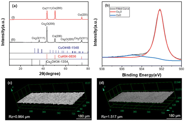 | ||
| Fig. 3 (a) XRD scan spectra pattern of copper(I) before and (II) after oxidation; (b) XPS spectra of copper after oxidation; images of roughness test results (c) before and (d) after copper oxidation. Adapted from ref. 63 with permission from Journal of Applied Polymer Science, Copyright 2022. | ||
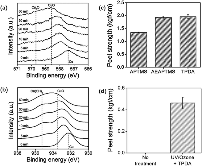 | ||
| Fig. 4 (a) Copper foil XPS LMM and (b) 2p core-level spectra taken from copper surfaces after different times of UV/ozone treatment; (c) peel strengths between a molded epoxy layer and copper substrates modified with 1 h of UV/ozone treatment and subsequent coating with different silane coupling agents; (d) peel strengths between a molded epoxy layer and bare (left) and UV/ozone-treated and then N-(3-trimethoxysilylpropyl)diethylenetriamine coated (right) copper foil substrates. The UV/ozone treatment time is 1 h. Adapted from ref. 64 with permission from Journal of Industrial and Engineering Chemistry, Copyright 2017. | ||
Improving the roughness and chemical composition of copper surfaces through mechanical grinding, chemical etching, silanization, and other surface treatments can effectively enhance the adhesion of thin films and copper foils. However, high-frequency electronic products need a low-profile copper foil with a smooth surface to reduce the signal-transmission loss caused by the skin effect.66 Therefore, the surface treatment of copper foil alone is not the optimal solution to increase the bond strength between copper foil and film layers. Changing the composition of reactive groups on the film surface, i.e., surface treatment of the film or introduction of the target monomers to synthesize new thin-film material, is necessary.
3 Insulation base film and its modification progress for 2L-FCCL
3.1 Insulation base film for flexible copper-clad laminates
The insulating base film is one of the components of 2L-FCCL. This type of film material should have good dielectric insulation, heat resistance, chemical resistance, dimensional stability, and flexural and mechanical properties and low Dk and Df. Table 2 lists common insulating base films.| Insulating base film type | Advantages | Faults | Reference |
|---|---|---|---|
| Polyimide (PI) | Heat resistance, weather resistance, and chemical resistance are good; good dielectric and mechanical properties | High moisture absorption rate | 67–70 |
| Liquid-crystal polymer (LCP) | Good heat resistance and chemical resistance; good electrical insulation, good dimensional stability, good mechanical properties; low expansion coefficient | Poor bonding ability; the vertical and horizontal orientation difference is large; easy to fibrillate | 71–75 |
| Poly(ethylene glycol terephthalate) (PET) | Good mechanical properties, good dimensional stability, good dielectric properties, low moisture absorption | Poor heat resistance, low melting point | 76–78 |
| Polyphenylene ethers (PPO) | High Tg, low Dk and Df | Poor flowability, poor solubility, not self-curing | 79 |
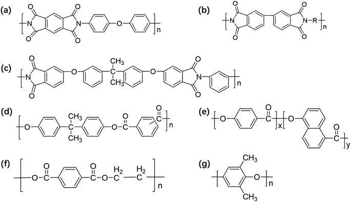 | ||
| Fig. 5 Structure of (a) Kapton, (b) Upilex, (c) Ultem, (d) U-polymer, (e) Vectran, (f) PET, and (g) PPO. | ||
Owing to the large number of imide structures in the main chain of PI, the symmetrically conjugated imide rings restrict the activity of free electrons, conferring PI with good electrical insulation properties. In addition, the polar group C![[double bond, length as m-dash]](https://www.rsc.org/images/entities/char_e001.gif) O on the PI can form chemical bonding with other materials during bonding, increasing the interlayer bonding strength. PI with excellent thermal stability, mechanical properties, chemical resistance, electrical insulation properties, and other properties has been extensively used in the electronic field.68–70
O on the PI can form chemical bonding with other materials during bonding, increasing the interlayer bonding strength. PI with excellent thermal stability, mechanical properties, chemical resistance, electrical insulation properties, and other properties has been extensively used in the electronic field.68–70
LCPs have a unique molecular structure and thermal behavior. After being dissolved or melted by a solvent to form a phase between liquid and crystal, i.e., the liquid-crystal state, the molecules assemble in a disordered position but maintain a certain degree of molecular orientation, with good anisotropy.71–73 This feature provides LCPs with excellent properties such as self-reinforcement, excellent heat and chemical resistance, and high tensile and compressive strengths.74,75 FCCLs prepared from LCP films have outstanding properties, such as high heat resistance, high dimensional stability, less water absorption, and low Df.
At the beginning of the last century, Hunter produced unsubstituted polyphenylene ether (PPO/PPE) (Fig. 5g), which is not commercialized because of its low yield and low shrinkage. Hay prepared a high-yield commercially available PPO product using 2,6-dimethylphenol as the monomer in 1957.87 PPO is widely cited in electronics, medical devices, aerospace, and other fields for its superior dielectric properties, dimensional stability, low water absorption, chemical resistance, and other properties. On the one hand, the large rigidity of PPO, causes problems such as high viscosity, poor fluidity, and difficulty in processing and forming. On the other hand, the surface roughness of PPO film is small with no polar groups in the molecule, so the mechanical bonding with the metal layer is weak and chemical bonding does not occur. The inherent properties of this polymer make it less commonly used in FCCLs and more commonly high-performance copper-clad laminates.79
In summary, although various types of films exist, the current films used to prepare FCCL are primarily PI film and LCP film. This phenomenon is due to the performance differences among various film types.
3.2 Surface treatment and modification of PI films
PI film has excellent overall performance and a similar coefficient of expansion as copper. Thus, the adhesive strength between the copper foil can be high. However, the moisture absorption rate of PI is high, and the water absorbed in the medium evaporates during the high-temperature processing of the sheet, causing the sheet to have problems such as oxidation of the copper foil and reduction in peeling strength between the copper foil and PI film. The dielectric properties of FCCLs and the stability of the signal transmission are also affected.88 In this regard, researchers proposed methods to introduce porous structures,89 large-volume cells,90 and low-polarizability groups91 to prepare PI films with low Dk values, guaranteeing that FCCLs can efficiently and stably transmit signals. Unfortunately, the changes in the bond strength of the PI and copper layers are neglected in these studies. As a key property of FCCLs, bonding strength should be further investigated to improve the surface morphology of PI film and should be increased to satisfy the current demand of 5G.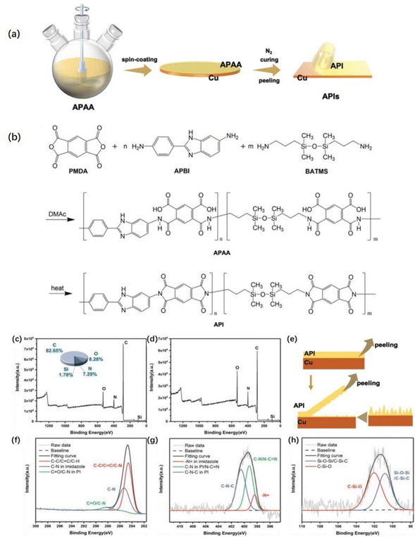 | ||
| Fig. 6 (a) Schematic of the synthesis procedure of adhesive polyimide (API), and (b) the reaction principle of API precursor solution (APAA) and API; XPS full (wide-scan) spectra (the illustration shows the element-content distribution) of (c) copper surface and (d) API-2 surface after peeling test; (e) schematic of the peeling process showing the principle of adhesion; (f) C 1s, (g) N 1s, and (h) Si 2p peaks of copper surface after peeling test by XPS. Adapted from ref. 101 with permission from Advanced Materials Interfaces, Copyright 2022. | ||
Thermoplastic PI (TPI) was coated onto both sides of the PI film to obtain a TPI/PI/TPI multilayer film. The film and copper foil were laminated by hot lamination, and FCCLs with a peel strength of 1.22 N mm−1 were obtained at a hot-pressing temperature of 360 °C and a hot-pressing time of 60 s.20 TPI and PI have good compatibility because of their similar structure.105,106 When asymmetric biphenyl-tetracarboxylic acid dianhydride was introduced into the molecular structure of TPI, the packing density and interaction force between molecular chains decreased.107,108 TPI with increased molecular chain mobility can diffuse thoroughly on the PI film, and the adhesion between the two is good. TPI can effectively infiltrate the copper surface and wrap small copper nodules; carbon compounds can be found on the surface of stripped copper foil. A good physical occlusion is formed between TPI and copper foil, and the bonding strength between the film and copper is enhanced.109 Therefore, in the preparation of 2L-FCCL, TPI plays a role in bonding the two materials.
Chen et al.110 used polyethyleneimine (PEI) and glutaraldehyde (GA) as modifiers. The secondary amine groups in the PEI molecule enabled PEI to form a network structure in the presence of GA to form chelates with heavy-metal ions and to react with carboxylic acids to form amide groups. The outcome was the improved peeling strength of the PI film from the copper foil.
The plasma pretreatment of the film allows nanoscale microgrooves and chemical groups to form on the film surface, enlarging the contact area between the PI film and the copper foil and allowing the formation of additional chemical reaction sites.111,112 Liu et al.113 treated PI film with oxygen plasma to encourage the generation of hydroxyl groups on the film surface and increase the surface roughness before immersing the treated PI film in an organosilane solution to induce the formation of Si–O–C bonds between the organosilane and hydroxyl groups. Wang et al.114 processed PI films with Ar–H2, Ar, and Ar–N2 plasma gases. The surface roughness of the films processed with plasma gases increases. After being treated with Ar plasma, the amount of C–O and C![[double bond, length as m-dash]](https://www.rsc.org/images/entities/char_e001.gif) O on the film surface noticeably increases, and the degree of anti-peeling of Ar–N2 plasma-treated copper foil surface is significantly better than that of others. Jin et al.115 grafted amino acids onto PI film by helical wave plasma, and the peel strength between the treated film and copper foil was > 8.0 N cm−1. Fig. 7 shows that dense clusters of copper were formed on the treated PI film, and the amino group was successfully grafted on the PI film. The increased roughness of the copper film provides a large number of mechanical riveting sites for PI, and the grafting of amino groups improves the surface composition of PI film. The chelate formed by the C–N functional group and copper has strong chemical bonding to improve the bonding strength between materials.114
O on the film surface noticeably increases, and the degree of anti-peeling of Ar–N2 plasma-treated copper foil surface is significantly better than that of others. Jin et al.115 grafted amino acids onto PI film by helical wave plasma, and the peel strength between the treated film and copper foil was > 8.0 N cm−1. Fig. 7 shows that dense clusters of copper were formed on the treated PI film, and the amino group was successfully grafted on the PI film. The increased roughness of the copper film provides a large number of mechanical riveting sites for PI, and the grafting of amino groups improves the surface composition of PI film. The chelate formed by the C–N functional group and copper has strong chemical bonding to improve the bonding strength between materials.114
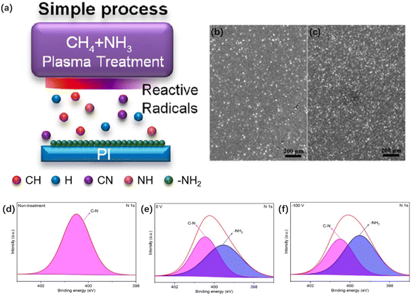 | ||
| Fig. 7 (a) Schematic depicting the grafting of amino groups onto PI films through HWP treatment; FE-SEM images of (b) a PI film under no treatment after copper foil plating and (c) a PI film subjected to plasma treatment at a −Vs of 100 V after copper foil plating; N 1s XPS profiles of the PI films after no treatment and plasma treatment at various Vs values: (d) N 1s, no treatment; (e) N 1s, 0 V; (f) N 1s, −100 V. Adapted from ref. 115 with permission from Materials, Copyright 2023. | ||
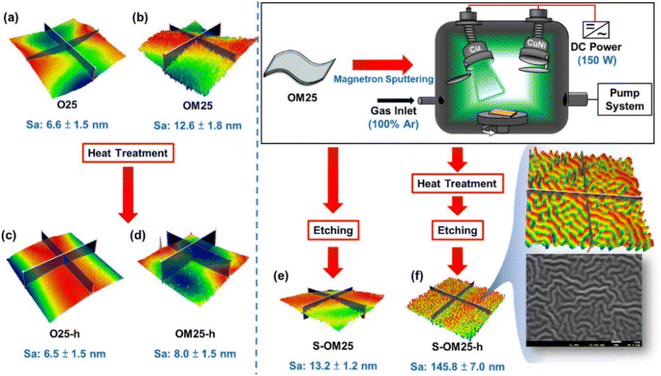 | ||
| Fig. 8 Schematic of PI film samples under sputtering, heat treatment, and etching. Note: sample code h represents the heat-treated sample. Adapted from ref. 116 with permission from ACS Omega, Copyright 2023. | ||
Pd salt, N,N′-dimethyl-dimethylamino ethyl methacrylate, trimethylpropane triacrylate, and tert-butyl peroxybenzoate (TBPB) can be used to form a heat-cured Pd composite ink. After the ink was spin-coated onto a PI film, the attachment of the chemically deposited copper foil onto the PI film was strengthened and the electrical resistivity was obtained as a sheet of about 1.3 × 10⁻⁶ Ω cm.118 You et al.119 dip-coated the complex-containing compounds on PI and found that the free radicals generated by the decomposition of TBPB promoted the reaction between 4-vinylpyridine and the PI film, with fine adhesion of the copper layer occurring after chemical copper plating.
The surface treatment and modification of PI membranes have generated significant research results; however, in-depth research on PI membranes is still needed. The bonding mechanism of the adhesive interface must be investigated by further exploring the peeling interface of PI film and copper foil to optimize the molecular structure of PI and improve the interlayer bonding performance.
3.3 LCP modification
Compared with PI, LCPs have lower coefficient of thermal expansion and hygroscopicity, good electrical properties, and chemical resistance, enabling the latter to maintain excellent stability in humid environments. However, the main-chain benzene-ring structure of PAR and the regular structure of the benzene ring make the surface of the membrane weakly polar, conferring difficulty in the bonding of the PAR surface with the copper layer.120–122 To solve the weak bonding ability and low bond strength between LCPs and copper foil, researchers proposed various methods for LCP surface modification, such as laser etching, UV irradiation, plasma treatment, and reaction etching.Laser etching adds roughness between the copper foil and the LCP, thereby enhancing their mechanical adhesion. Jia et al.39 suggested a laser-integrated fabrication method for double-layer FCCLs, including LCP laser etching, copper-foil laser etching, and laser soldering. A regular organization was prepared on the copper-foil surface by laser etching. The LCP surface was irradiated by UV laser, and the copper foil was welded to the LCPs by laser conductive welding. This method enables the direct bonding of materials and produces a high bonding strength between the prepared samples. In addition, this fabrication process is simple and features low cost and high production efficiency.
Second, UV irradiation introduces hydrophilic (e.g., carbonyl and carboxyl) groups, which increase the surface wettability of LCPs and form a hydrophilic rough surface on the film to improve the adhesive strength.123,124 Fig. 9 also shows that plasma treatment using oxygen and nitrogen removes impurities from the membrane surface and introduces polar groups to improve its weak polarity.125
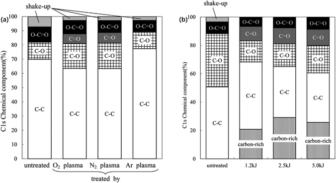 | ||
| Fig. 9 (a) C 1s chemical components of untreated and plasma-treated LCP film surfaces; (b) C 1s chemical components of the surface of a LCP film, untreated and after O2 plasma treatments under different conditions. Adapted from ref. 125 with permission from Progress in Organic Coatings, Copyright 2016. | ||
When O2 and N2 plasma were used to treat LCP membrane, the ester bond in molecular structure broke into hydroxyl group, increasing the polarity of the membrane surface. The introduced groups can increase the affinity of the film to the metal and easily form carbon–oxygen–copper type chemical bonds with the surface of copper foil. The chemical bond energy is 1–2 orders of magnitude higher than the intermolecular force, causing the materials to have a high bonding strength. Redhwan et al.126 used oxygen plasma to activate and increase the active sites on the surface of LCP membrane and then pressed the membrane at 230 °C for 1 h after cold rolling. The carbon-rich LCP and copper foil diffused carbon and copper atoms to each other's surfaces. The mutual diffusion of materials and the formation of oxide layer promoted the formation of strong chemical bonds between the materials.
Third, chemical etching introduces hydrophilic groups onto the membrane surface and forms nanoscale roughness, improving the wettability and strengthens the mechanical interlocking strength between copper foil and LCP. Zhou et al.127 pretreated LCPs by three etchant pretreatments, followed by the chemical plating and electroplating of LCP films. Fig. 10 shows that potassium permanganate had the best etching effect with a maximum bond strength of 12.08 MPa.
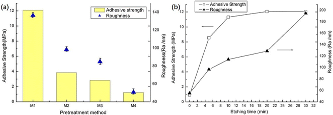 | ||
| Fig. 10 (a) Roughness of LCP surface and adhesive strength between copper and LCPs with different pretreatment chemicals: M1 etched by KMnO4, M2 by NaOH and carboxylic acid derivatives followed by CrO3 and H2SO4, M3 by CrO3 and H2SO4, and M4 by original LCPs; (b) adhesive strength of copper onto LCPs as a function of etching time (etched by KMnO4). Adapted from ref. 127 with permission from Applied Surface Science, Copyright 2012. | ||
When the molecular chain structure of the film has flexible chain segments, the bonding strength of the metal is high. Hence, flexible structures, such as ether bond, siloxy group and methylene group, were introduced into the structure of polyaryl ester to increase the flexibility of molecular chain and facilitate intermolecular movement.128–130 This process promotes the mutual diffusion of molecular chain segments during thermal motion, similar to the mutual dissolution that occurs in the surface layer. The infiltration effect between the copper foil is improved, and the bonding strength is higher. When the molecular structure contains an appropriate amount of N-containing groups, the adhesion to copper foil can be improved due to the coordination between copper and N-containing groups. Ren et al.131 synthesized a new type of nitrogen-containing heterocyclic polyaryl ester film, and the hydrophilicity of the film was improved due to the influence of N-containing heterocyclic structure. The introduced imine groups can form a coordination between copper and copper, and chemical bonds between copper foils, greatly improving the bonding strength between materials.
In addition to the above surface modifications, the introduction of polar groups into the molecular chain is an effective method to improve the chemical composition of the surface. In 2018, Zhou et al.132 synthesized a novel PAR containing heteroanthracene groups with a tensile strength of 88.6–108.3 MPa, an elongation at break of 2–3%, and a tensile modulus of 7–9 GPa. Nagane et al.133 used 4,4′-bis(4-hydroxyphenyl)pentanoic acid as a starting material to obtain a partially biobased bisphenol containing a pendant azide moiety, i.e., 4,4′-(5-azidopentane-2,2- diyl)bisphenol (AZBPA). AZBPA is polycondensed with isophthaloyl chloride (IPC), terephthaloyl chloride (TPC), and mixtures of IPC/TPC (50![[thin space (1/6-em)]](https://www.rsc.org/images/entities/char_2009.gif) :
:![[thin space (1/6-em)]](https://www.rsc.org/images/entities/char_2009.gif) 50 mol%) through a phase transfer-catalyzed interfacial polycondensation to produce aromatic polyesters containing pendant azide groups. At 170 °C/12 h, (co-)polyesters containing azide groups are thermally cross-linked to form network structures. The cross-linked polymers have higher tensile strength and Young's modulus and lower elongation at break than pure polyesters.134
50 mol%) through a phase transfer-catalyzed interfacial polycondensation to produce aromatic polyesters containing pendant azide groups. At 170 °C/12 h, (co-)polyesters containing azide groups are thermally cross-linked to form network structures. The cross-linked polymers have higher tensile strength and Young's modulus and lower elongation at break than pure polyesters.134
Extensive studies were conducted on the functional improvements of PAR, such as flame retardancy,135 optoelectronic properties,136–138 gas separation and transportation properties,139–141 and low dielectricity.28 Conversely, only a few works focused on enhancing the bonding strength between LCPs and copper foil. Research is still limited to the improvement in membrane surface composition by surface treatment, and investigations on the direct modification of LCPs molecular-chain backbone are still lacking.
4 Summary and outlook
Increasing the surface roughness of copper by mechanical milling, etching, and silanization effectively improves the adhesion between copper and thin films. However, the skin effect caused by the increase in roughness impairs the stability of FCCL signal transmission.The surface composition of PI film can be effectively improved by surface treatment, i.e., it provides a strong support site for bonding with copper foil. Modifications such as plasma treatment, laser etching, and thin-film metallization have nonnegligible drawbacks, and method such as the introduction of bulky groups into the molecular chain may affect the other properties of PI films. Thus, how to stabilize the comprehensive performance of FCCL while increasing the bond strength of PI film and copper foil remains a research focus.
Studies on increasing the adhesive properties of LCP-FCCL rely mostly on surface modification and neglect to fundamentally solve the weak surface polarity of LCP film. New PARs including polar groups must be synthesized to solve the problem at the source.
In conclusion, research on flexible copper laminates over the last decades has yielded good results. With the arrival of the 5G era, FCCL now requires an excellent combination of properties, such as stable and outstanding Dk/Df, a coefficient of thermal expansion that matches that of the copper foil, and very low water absorption. FCCL also requires that the adhesion between the film and copper remains strong. The bonding performance of the interlayer is affected by the changes in the surface morphology and composition of copper foils and films. How to identify the optimal surface composition to increase the peel strength of the interlayer requires further investigation. Furthermore, the optimization of the molecular structure of PI and LCPs to find a balance between increasing the bond strength and stabilizing all other properties remains a topic for future exploration.
Conflicts of interest
The authors declare no conflict of interest.Acknowledgements
The authors gratefully acknowledge the financial support of the Anhui Province Outstanding Young Talents Support Plan Project (No. gxyq2022099) and the Key Research and Development Program of Anhui Province (No. 202104b11020010).References
- C. Zhang, Y. L. Ueng, C. Studer and A. Burg, IEEE J. Emerg. Sel. Top. Circuits Syst., 2020, 10, 149–163 Search PubMed.
- B.-I. Noh, J.-W. Yoon, J.-H. Choi and S.-B. Jung, Microelectron. Eng., 2011, 88, 718–723 CrossRef CAS.
- L. Xue, Q. Liang and Y. Lu, J. Mater. Sci.: Mater. Electron., 2013, 24, 2211–2217 CrossRef CAS.
- A. Li, H. He, Y. Shen and Q. Li, J. Appl. Polym. Sci., 2023, 140, e54596 CrossRef CAS.
- W. J. Koros, C. J. Patton, R. M. Felder and S. J. Fincher, J. Polym. Sci. Polym. Phys. Ed., 1980, 18, 1485–1495 CrossRef CAS.
- Q. Xiang and F. Xiao, Constr. Build. Mater., 2020, 235, 117529 CrossRef CAS.
- X. Mi, N. Liang, H. Xu, J. Wu, Y. Jiang, B. Nie and D. Zhang, Prog. Mater. Sci., 2022, 130, 100977 CrossRef CAS.
- N. R. Paluvai, S. Mohanty and S. K. Nayak, Polym. Plast. Technol. Eng., 2014, 53, 1723–1758 CrossRef CAS.
- C. Jiao, Q. Shao, M. Wu, B. Zheng, Z. Guo, J. Yi, J. Zhang, J. Lin, S. Wu and M. Dong, Polymer, 2020, 190, 122196 CrossRef CAS.
- S. Durmaz, Ö. Özgenç, E. Avci and İ. Hakki Boyaci, J. Appl. Polym. Sci., 2020, 137, 48518 CrossRef CAS.
- R. Dong and L. Liu, Appl. Surf. Sci., 2016, 368, 378–387 CrossRef CAS.
- Y. Duan, Y. Huo and L. Duan, Colloids Surf., A, 2017, 535, 225–231 CrossRef CAS.
- J. Hu, J. Ma and W. Deng, Mater. Lett., 2008, 62, 2931–2934 CrossRef CAS.
- X. Kong, G. Liu and J. M. Curtis, Int. J. Adhes. Adhes., 2011, 31, 559–564 CrossRef CAS.
- V. García-Pacios, Y. Iwata, M. Colera and J. Miguel Martín-Martínez, Int. J. Adhes. Adhes., 2011, 31, 787–794 CrossRef.
- H. Qiu, X. Qiu, X. Dai and Z. Y. Sun, J. Mater. Chem. C, 2023, 11, 2930–2940 RSC.
- M. Miyauchi, Y. Ishida, Y. Ogasawara and R. Yokota, Polym. J., 2013, 45, 594–600 CrossRef CAS.
- X. Ren, Z. He, Z. Wang, Z. Pan, Y. Qi, S. Han, H. Yu and J. Liu, Polymer, 2023, 15, 3408 CAS.
- S. Benyahya, C. Aouf, S. Caillol, B. Boutevin, J. P. Pascault and H. Fulcrand, Ind. Crop. Prod., 2014, 53, 296–307 CrossRef CAS.
- X. Cao, J. Wen, C. Wei, X. Liu and G. He, High Perform. Polym., 2021, 33, 704–711 CrossRef CAS.
- S. Nishimura, M. Ueda and T. Ogura, US pat., 20090078368, 2009 Search PubMed.
- X. Wu, J. Cai and Y. Cheng, J. Appl. Polym. Sci., 2022, 139, 51972 CrossRef CAS.
- W. Peng, H. Lei, L. Qiu, F. Bao and M. Huang, Polym. Chem., 2022, 13, 3949–3955 RSC.
- H. T. Zuo, F. Gan, J. Dong, P. Zhang, X. Zhao and Q. H. Zhang, Chin. J. Polym. Sci., 2021, 39, 455–464 CrossRef CAS.
- X. Dong, M. Zheng, B. Wan, X. Liu, H. Xu and J. Zha, Materials, 2021, 14, 6266 CrossRef CAS PubMed.
- H. Li, J. Yang, S. Dong, F. Tian and X. Li, Polymer, 2020, 12, 879 CAS.
- G. Qiu, W. Ma and L. Wu, Polym.-Plast. Technol. Mater., 2020, 59, 1482–1491 CAS.
- H. Lu, D. Li, Y. Zhang, Z. Wu, H. Wang, S. Liu, G. Yan, J. Yang and G. Zhang, Polymer, 2021, 228, 123948 CrossRef CAS.
- Y. Zhang, G. M. Yan, J. Yang and G. Zhang, J. Appl. Polym. Sci., 2023, 140, e53975 CrossRef CAS.
- X. Guan, Z. Ma, Z. Xiang, Y. Ke, Y. Xia, H. Nie, G. Zhou, Q. Shi and J. Yin, Mater. Lett., 2022, 324, 132789 CrossRef CAS.
- Q. Chen, Nonferrous Met. Process., 2014, 43, 17–20 CrossRef CAS.
- H. Zhao, W. Chen, M. Wu and R. Li, Oxid. Met., 2018, 90, 203–215 CrossRef CAS.
- Y. Zheng, Print. Circ. Inform., 2004, 10, 14–16 Search PubMed.
- J. Liu, Print. Circ. Inform., 2015, 2, 13–20 Search PubMed.
- Z. Dong, X. Fei, B. Gong, X. Zhao and J. Nie, Materials, 2021, 14, 5498 CrossRef CAS PubMed.
- H. Venugopalan, K. Tankala and T. DebRoy, J. Am. Ceram. Soc., 1994, 77, 3045–3047 CrossRef CAS.
- H. S. Abdo, A. H. Seikh, J. A. Mohammed and M. S. Soliman, Materials, 2021, 14, 3971 CrossRef CAS PubMed.
- N. Nagel, ChemBioEng Rev., 2018, 5, 30–33 CrossRef CAS.
- L. Jia, H. Yang, Y. Wang, B. Zhang, H. Liu and J. Hao, Opt Laser. Eng., 2021, 139, 106509 CrossRef.
- A. Rudawska, I. Miturska-Barańska and E. Doluk, Materials, 2021, 14, 6938 CrossRef CAS PubMed.
- C. Bockenheimer, B. Valeske and W. Possart, Int. J. Adhes. Adhes., 2002, 22, 349–356 CrossRef CAS.
- A. Rudawska, I. Danczak, M. Müller and P. Valasek, Int. J. Adhes. Adhes., 2016, 70, 176–190 CrossRef CAS.
- B. Wang, X. Hu and P. Lu, Int. J. Adhes. Adhes., 2017, 73, 92–99 CrossRef CAS.
- A. Rudawska, Int. J. Adhes. Adhes., 2014, 50, 235–243 CrossRef CAS.
- R. Rechner, I. Jansen and E. Beyer, Int. J. Adhes. Adhes., 2010, 30, 595–601 CrossRef CAS.
- D. T. Pham, S. S. Dimov and P. V. Petkov, Int. J. Mach. Tools Manuf., 2007, 47, 618–626 CrossRef.
- M. Cutroneo, V. Havranek, A. Mackova, P. Malinsky, L. Silipigni, P. Slepicka, D. Fajstavr and L. Torrisi, Radiat. Eff. Defects Solids, 2022, 17, 71–84 CrossRef.
- C. Zheng, X. Zhang, Y. Zhang, J. Zhong, Y. Luan and L. Song, Opt. Lasers Eng., 2018, 105, 35–42 CrossRef.
- P. Pou, J. del Val, A. Riveiro, R. Comesaña, F. Arias-González, F. Lusquiños, M. Bountinguiza, F. Quintero and J. Pou, Appl. Surf. Sci., 2019, 475, 896–905 CrossRef CAS.
- A. Kurtovic, E. Brandl, T. Mertens and H. J. Maier, Int. J. Adhes. Adhes., 2013, 45, 112–117 CrossRef CAS.
- Z. Lei, Z. Tian, X. Chen, Y. Chen, J. Bi, S. Wu and H. Sun, Surf. Coat. Technol., 2019, 361, 249–254 CrossRef CAS.
- E. Hernandez, M. Alfano, G. Lubineau and U. Buttner, Int. J. Adhes. Adhes., 2016, 64, 23–32 CrossRef CAS.
- A. H. A. Lutey and L. Romoli, Coat. Technol., 2019, 360, 358–368 CrossRef CAS.
- L. Jia, H. Yang, Y. Wang, B. Zhang, H. Liu and J. Hao, J. Manuf. Process., 2020, 57, 677–690 CrossRef.
- S. P. Wang, K. X. Wei, W. Wei, Q. B. Du and I. V. Alexandrov, Phys. Status Solidi A, 2022, 219, 2100735 CrossRef CAS.
- H. Liu, H. Yang, H. He, L. Jia and Q. Gao, Chin. J. Lasers, 2022, 49, 0202011 CrossRef.
- H. Chen, Z. Shen, P. Li and L. Zhang, J. Manuf. Process., 2023, 86, 10–29 CrossRef.
- C. Y. Lee, P. C. Lin, C. H. Yang and C. E. Ho, Surf. Coat. Technol., 2020, 386, 125471 CrossRef CAS.
- L. Luo, S. Zhang, Y. Qiang, I. Bozdag, S. Chen, M. Tang, J. Gao and Z. Qin, J. Adhes. Sci. Technol., 2018, 32, 1452–1470 CrossRef CAS.
- A. Strålin and T. Hjertberg, Appl. Surf. Sci., 1994, 74, 263–275 CrossRef.
- D. V. Smovzh, S. Z. Sakhapov, V. A Andryushchenko, D. V. Sorokin, I. A. Betke, S. V. Komlina, S. V. Starinskiy and E. A Maximovskiy, Interfacial Phenom. Heat Transf., 2023, 11, 1–10 CrossRef.
- Y. Y. Yue, Z. X. Liu, T. T. Wan and P. C. Wang, Prog. Org. Coat., 2013, 76, 835–843 CrossRef CAS.
- Y. Chen, H. Feng, Y. Su, J. Li, Z. Xu, Y. Li, N. Li, Y. He, Y. Hong and S. Wang, J. Appl. Polym. Sci., 2022, 139, e52644 CrossRef CAS.
- S. Bok, G. H. Lim and B. Lim, J. Ind. Eng. Chem., 2017, 46, 199–202 CrossRef CAS.
- H. Zhou, D. Y. Wei, Y. Fan, H. Chen, Y. S. Yang, J. J. Yu and L. G. Jin, Mater. Sci. Eng. B, 2016, 203, 13–18 CrossRef.
- B. Li, K. Dastafkan, Y. Shen, L. Wang, Y. Ma, Z. Wang and C. Zhao, J. Electrochem. Soc., 2023, 170, 092503 CrossRef.
- X. Yu, W. Liang, J. Cao and D. Wu, Polymer, 2017, 9, 451 Search PubMed.
- G. Qiu, W. Ma and L. Wu, Polym. Int., 2020, 69, 485–491 CrossRef CAS.
- W. Chen, F. Liu, M. Ji and S. Yang, High Perform. Polym., 2017, 29, 501–512 CrossRef CAS.
- P. Zhang, L. Zhang, K. Zhang, J. Zhao and Y. Li, Cryst., 2021, 11, 1383 CrossRef CAS.
- Q. Guan, S. J. Picken, S. S. Sheiko and T. J. Dingemans, Macromolecules, 2017, 50, 3903–3910 CrossRef CAS.
- A. Abu Obaid, S. Yarlagadda and J. W. Gillespie, J. Compos. Mater., 2015, 50, 339–350 CrossRef.
- X. Wang, V. Ho, R. A. Segalman and D. G. Cahill, Macromolecules, 2013, 46, 4937–4943 CrossRef CAS.
- X. L. Lyu, A. Xiao, D. Shi, Y. Li, Z. Shen, E. Q. Chen, S. Zheng, X. H. Fan and Q. F. Zhou, Polymer, 2020, 202, 122740 CrossRef CAS.
- J. D. Menczel, G. L. Collins and S. K. Saw, J. Therm. Anal. Calorim., 1997, 49, 201–208 CrossRef CAS.
- A. K. Singh, R. Bedi and B. S. Kaith, Composites, Part B, 2021, 219, 108928 CrossRef CAS.
- G. P. Karayannidis, D. S. Achilias, I. D. Sideridou and D. N. Bikiaris, Eur. Polym. J., 2005, 41, 201–210 CrossRef CAS.
- X. Liu, Y. Wen, X. Chen, T. Tang and E. Mijowska, Sci. Total Environ., 2020, 723, 138055 CrossRef CAS PubMed.
- Y. Qin, X. Yu, Z. Fang, X. He, M. Qu, M. Han, D. Lu, K. Xue and K. Wang, J. Phys. D Appl. Phys., 2023, 56, 064002 CrossRef.
- M. T. Bogert and R. R. Renshaw, J. Am. Chem. Soc., 1908, 30, 1135–1144 CrossRef CAS.
- A. N. Hammoud, E. D. Baumann, E. Overton, I. T. Myers, J. L. Suthar, W. Khachen and J. R. Laghari, In Proceedings] 1992 Annual Report: Conference on Electrical Insulation and Dielectric Phenomena, 1992, pp. 549–554 Search PubMed.
- H. Finkelmann, Angew. Chem., Int. Ed., 1987, 26, 816–824 CrossRef.
- H. Zhou, M. G. Forest and Q. Wang, SIAM J. Appl. Math., 2000, 60, 1177–1204 CrossRef.
- Z. Ophir and Y. Ide, Polym. Eng. Sci., 1983, 23, 792–796 CrossRef CAS.
- T. Odijk, Macromolecules, 1986, 19, 2313–2329 CrossRef CAS.
- N. Boden, R. J. Bushby and J. Clements, J. Chem. Phys., 1993, 98, 5920–5931 CrossRef CAS.
- A. S. Hay, H. S. Blanchard, G. F. Endres and J. W. Eustance, J. Am. Chem. Soc., 1959, 81, 6335–6336 CrossRef CAS.
- L. Wang, C. Liu, S. Shen, M. Xu and X. Liu, Adv. Ind. Eng. Polym. Res., 2020, 3, 138–148 Search PubMed.
- Y. Ma, Z. He, Z. Liao, J. Xie, H. Yue and X. Gao, J. Mater. Sci., 2021, 56, 7397–7408 CrossRef CAS.
- W. Chen, Z. Zhou, T. Yang, R. Bei, Y. Zhang, S. Liu, Z. Chi, X. Chen and J. Xu, React. Funct. Polym., 2016, 108, 71–77 CrossRef CAS.
- K. Hu, Q. Ye, Y. Fan, J. Nan, F. Chen, Y. Gao and Y. Shen, Eur. Polym. J., 2021, 157, 110566 CrossRef CAS.
- G. Xue, J. F. Ding, P. Lu and J. Dong, J. Phys. Chem., 1991, 95, 7380–7384 CrossRef CAS.
- G. Xue, Q. P. Dai and S. G. Jiang, J. Am. Chem. Soc., 1988, 110, 2393–2395 CrossRef CAS.
- W. J. Eilbeck, F. Holmes and A. E. Underhill, J. Chem. Soc. A, 1967, 757–761 RSC.
- R. Haight, R. C. White, B. D. Silverman and P. S. Ho, J. Vac. Sci. Technol., A, 1988, 6, 2188–2199 CrossRef CAS.
- R. C. White, R. Haight, B. D. Silverman and P. S. Ho, Appl. Phys. Lett., 1987, 51, 481–483 CrossRef CAS.
- M. B. Chan-Park and S. S. Tan, Int. J. Adhes. Adhes., 2002, 22, 471–475 CrossRef CAS.
- N. Inagaki, S. Tasaka and M. Masumoto, Macromolecules, 1996, 29, 1642–1648 CrossRef CAS.
- W. C. Wang, R. H. Vora, E. T. Kang and K. G. Neoh, Polym. Eng. Sci., 2004, 44, 362–375 CrossRef CAS.
- J. Seo, J. Kang, K. Cho and C. E. Park, J. Adhes. Sci. Technol., 2002, 16, 1839–1851 CrossRef CAS.
- A. Zhong, J. Li, G. Zhang and R. Sun, Adv. Mater. Interfaces, 2022, 9, 2101745 CrossRef CAS.
- I. H. Tseng, T.-T. Hsieh, C.-H. Lin, M.-H. Tsai, D.-L. Ma and C.-J. Ko, Prog. Org. Coat., 2018, 124, 92–98 CrossRef CAS.
- T. Chen, X. He and Q. Lu, ACS Appl. Polym. Mater., 2023, 5, 5436–5444 CrossRef CAS.
- Y. J. Park, D. M. Yu, J. H. Ahn, J. H. Choi and Y. T. Hong, Macromol. Res., 2012, 20, 168–173 CrossRef CAS.
- W. Ye, W. Wu, X. Hu, G. Lin, J. Guo, H. Qu and J. Zhao, Compos. Sci. Technol., 2019, 182, 107671 CrossRef CAS.
- A. Rivera Nicholls, M. Pellisier, Y. Perez, J. A. Stock, K. Kull, T. Julien, J. Eubank and J. P. Harmon, Polym. Eng. Sci., 2019, 59, 1948–1959 CrossRef CAS.
- J. Yao, G. Li, C. W. M. Bastiaansen and T. Peijs, Polymer, 2015, 76, 46–51 CrossRef CAS.
- D. Huang, J. S. Liu, J. H. Li, F. C. Wang, K. Li, Q. Liu, H. M. Yin, G. P. Zhang and R. Sun, ACS Appl. Polym. Mater., 2022, 4, 8508–8519 CrossRef CAS.
- X. Cao, J. Wen, C. Wei, X. Liu and G. He, High Perform. Polym., 2021, 33, 704–711 CrossRef CAS.
- J.-J. Chen, Q. An, R. D. Rodriguez, E. Sheremet, Y. Wang, E. Sowade, R. R. Baumann and Z.-S. Feng, Appl. Surf. Sci., 2019, 487, 503–509 CrossRef CAS.
- W.-Y. Ahn and J. S. Jang, Electron. Mater. Lett., 2014, 10, 845–850 CrossRef CAS.
- K. Usami, T. Ishijima and H. Toyoda, Thin Solid Films, 2012, 521, 22–26 CrossRef CAS.
- J.-N. Liu, M. C. Sil, R. Cheng, S.-P. Feng and C.-M. Chen, JOM, 2020, 72, 3529–3537 CrossRef CAS.
- E. Wang, Y. Song, L. Shang, G. Zhang, S. Wang and S. Topogr, Metrol. Prop., 2022, 10, 045005 CAS.
- C. Jin, C. Wang, S. Song, Y. Zhang, J. Wan, L. He, Z. Qiao and P. E, Mater., 2023, 16, 6214 CrossRef CAS PubMed.
- Y.-N. Tsai, S.-C. Chin, H.-Y. Chen, M.-S. Li, Y.-S. Chen, Y.-L. Wang, T.-I. Yang, M.-H. Tsai and I.-H. Tseng, ACS Omega, 2023, 8, 5752–5759 CrossRef CAS PubMed.
- Y.-N. Tsai, S.-C. Chin, H.-Y. Chen, T.-I. Yang, M.-H. Tsai and I.-H. Tseng, RSC Adv., 2023, 13, 13880–13885 RSC.
- P.-C. Wang, Y.-M. Liu, C.-P. Chang, Y.-Y. Liao, Y.-Y. Peng and M.-D. Ger, J. Taiwan Inst. Chem. Eng., 2017, 80, 963–969 CrossRef CAS.
- J.-L. You, C.-P. Chang, N.-W. Pu, Y.-S. Chen, L.-H. Wang, K.-H. Pan and M.-D. Ger, Appl. Surf. Sci., 2022, 599, 153990 CrossRef CAS.
- M. G. Dobb and J. E. McIntyre, in Liquid Crystal Polymers II/III, ed. N. A. Platé, Springer Berlin Heidelberg, 1984, pp. 61–98 Search PubMed.
- W. J. Jackson Jr, MCLC S&T, Sect. B: Nonlinear Opt., 1989, 169, 23–49 Search PubMed.
- P. Wei, M. Cakmak, Y. Chen, X. Wang, Y. Wang and Y. Wang, J. Appl. Polym. Sci., 2014, 131, 40487 CrossRef.
- E. Kraus, B. Baudrit, P. Heidemeyer, M. Bastian, O. Stoyanov and I. Starostina, J. Adhes., 2017, 93, 204–215 CrossRef CAS.
- T. Sugiyama, Y. Iimori, K. Baba, M. Watanabe and H. Honma, J. Electrochem. Soc., 2009, 156, D360 CrossRef CAS.
- K. Miyauchi, H. Watanabe and M. Yuasa, Prog. Org. Coat., 2016, 94, 73–78 CrossRef CAS.
- T. Z. Redhwan, A. U. Alam, M. Catalano, L. Wang, M. J. Kim, Y. M. Haddara and M. M. R. Howlader, Mater. Lett., 2017, 212, 214–217 CrossRef.
- M. Zhou, W. Zhang, D. Ding and M. Li, Appl. Surf. Sci., 2012, 258, 2643–2647 CrossRef CAS.
- D. Serbezeanu, T. Vlad-Bubulac, C. Hamciuc and M. Aflori, Macromol. Chem. Phys., 2010, 211, 1460–1471 CrossRef CAS.
- B. V. Tawade, J. K Salunke, P. S. Sane and P. P. Wadgaonkar, J. Polym. Res., 2014, 21, 617 CrossRef.
- M. Athianna, K. Balaji, S. C. Murugavel, C. H. Yuan and L. Z. Dai, Polym. Sci., Ser. B, 2020, 62, 245–255 CrossRef.
- D. Ren, Y. Li, S. Ren, T. Tian and L. Wang, J. Membr. Sci., 2020, 610, 118295 CrossRef CAS.
- Y.-T. Zhou, S.-R. Sheng, C.-C. Tang, C. Song, Z.-Z. Huang and X.-L. Liu, High Perform. Polym., 2017, 30, 1203–1209 CrossRef.
- S. S. Nagane, S. S. Kuhire, U. A. Jadhav, S. A. Dhanmane and P. P. Wadgaonkar, J. Polym. Sci., Part A: Polym. Chem., 2019, 57, 630–640 CrossRef CAS.
- S. S. Nagane, S. Verma, B. V. Tawade, P. S. Sane, S. A. Dhanmane and P. P. Wadgaonkar, Eur. Polym. J., 2019, 116, 180–189 CrossRef CAS.
- Z.-F. Wu, G. Zhang, G.-M. Yan, J.-H. Lu and J. Yang, J. Polym. Res., 2018, 25, 170 CrossRef.
- S. Meng, N. Sun, K. Su, X. Zhao, D. Wang, H. Zhou and C. Chen, High Perform. Polym., 2017, 30, 864–871 CrossRef.
- W. Cai, X. Wu, T. Xiao, H. Niu, X. Bai, C. Wang, W. Wang and Y. Zhang, Appl. Surf. Sci., 2018, 431, 187–196 CrossRef CAS.
- Y. Zhang, Z. Lei, G.-M. Yan, J. Yang and G. Zhang, Mater. Today Commun., 2021, 28, 102643 CrossRef CAS.
- S. Yu, S. Li, Y. Liu, S. Cui and X. Shen, J. Membr. Sci., 2019, 573, 425–438 CrossRef CAS.
- R. D. Shingte, D. Chatterjee, B. V. Tawade, B. Shrimant and P. P. Wadgaonkar, J. Macromol. Sci., Part A: Pure Appl.Chem., 2019, 56, 136–145 CrossRef CAS.
- H. Sun, S. Bao, H. Zhao, Y. Chen, Y. Wang, C. Jiang, P. Li and Q. Jason Niu, Sep. Purif. Technol., 2020, 251, 117370 CrossRef CAS.
| This journal is © The Royal Society of Chemistry 2024 |

