 Open Access Article
Creative Commons Attribution 3.0 Unported Licence
An electrochemically synthesized molecularly imprinted polymer for highly selective detection of breast cancer biomarker CA 15-3: a promising point-of-care biosensor†
Daniela Oliveiraabcd,
Yonny Romaguera Barcelay b and
Felismina T. C. Moreira
 *acd
*acd
aCIETI – LabRISE-School of Engineering, Polytechnic of Porto, R. Dr António Bernardino de Almeida, 431, 4249-015 Porto, Portugal
bCEMMPRE, Department of Chemical Engineering, University of Coimbra, Rua Sílvio Lima – Pólo II, 3030-790 Coimbra, Portugal
cBioMark@ISEP, School of Engineering of Polytechnique School of Porto, Porto, Portugal. E-mail: ftm@isep.ipp.pt
dLABBELS/CEB, Centre of Biological Engineering, University of Minho, Braga, Portugal
First published on 13th May 2024
Abstract
In this study, a molecularly imprinted polymer film (MIP) was prepared on the surface of a disposable carbon screen-printed electrode (C-SPE) using (3-acrylamidopropyl)trimethylammonium chloride (AMPTMA) as a functional monomer and the cancer biomarker carbohydrate antigen 15-3 (CA 15-3) as a template. The MIP was synthesized by in situ electropolymerization (ELP) of the AMPTMA monomer in the presence of the CA 15-3 protein on the C-SPE surface. The target was subsequently removed from the polymer matrix by the action of proteinase K, resulting in imprinted cavities with a high affinity for CA 15-3. Electrochemical techniques such as cyclic voltammetry (CV) and electrochemical impedance spectroscopy (EIS) were used to characterize the different phases of the sensor assembly. Chemical and morphological analysis was performed using RAMAN and scanning electron microscopy (SEM). CA 15-3 was successfully detected in a wide working range from 0.001 U mL−1 to 100 U mL−1 with a correlation coefficient (R2) of 0.994 in 20 min. The MIP sensor showed minimal interference with other cancer proteins (CEA and CA 125). Overall, the developed device provides a rapid, sensitive, and cost-effective response in the detection of CA 15-3. Importantly, this comprehensive approach appears suitable for point-of-care (PoC) use, particularly in a clinical context.
1. Introduction
Glycoproteins play crucial roles in fundamental biological processes such as molecular recognition, cell signaling, the immune response, and the regulation of cell development. Therefore, the identification of glycoprotein levels has intensified since the expression of these substances can provide direct information on the evolution of pathological conditions and the physiological state.1,2 CA 15-3, a glycoprotein of approximately 400 kDa like mucin 1 (MUC1), is secreted by breast cancer cells and is the most commonly used serum biomarker for monitoring breast cancer.3Glycoproteins normally occur in an organism either as soluble or membrane-bound molecules. These glycoproteins can differ according to the type, length, and linkage of the carbohydrate components and even the degree of saturation of the potential glycosylation sites on the protein itself.4 Divergent glycolysis is associated with differential expression of enzymes such as glycosyltransferases and glycosidases. The abnormal expression of these enzymes leads to cancer cells producing glycoproteins with specific, cancer-associated deviations in glycan structures.5 Some of these glycan structures and glycoproteins are known tumour markers, such as CA 15-3, which is used as a breast cancer marker.6,7
Thus, its primary applications cover post-operative surveillance, consideration of the continuation of a specific treatment, the possibility of discontinuing that therapeutic protocol, as well as the evaluation of transitioning to viable alternatives.8,9 Healthy individuals typically exhibit CA 15-3 levels below 30 U mL−1, in contrast to patients who, after surgery, show higher concentrations (>30 U mL−1). On such a basis, much attention has been devoted to developing procedures to detect the presence of CA 15-3 protein at very low concentrations in a physiological environment and biological fluids.8
Currently, detection of the CA 15-3 biomarker is often carried out using immunoassays that employ various signal transduction approaches, such as ELISA,10,11 flow fluorescence,12 chemiluminescence,13,14 electrochemiluminescence,15,16 and electrochemistry.17,18 Although these biosensors are highly selective due to the use of corresponding natural biomolecules such as enzymes, antibodies, aptamers, and lectins, they often present problems of high cost, tendency to denature, and low abundance. In addition, the procedures for these methods are often time-consuming and expensive.19 Given these limitations, there is growing interested in approaches that aim to mimic natural recognition systems using synthetic analogues of molecular imprinting polymers (MIPs).20,21 Plastic antibodies relying on MIPs are a cost-effective technology compared to natural recognition elements because they are easier to produce than natural antibodies as they are synthesized by chemical processes and avoid the complexity of biological systems. They are stable under different conditions, which lowers storage costs, and unlike natural antibodies, they are reusable, which lowers overall costs. In addition, MIPs can be customized for specific target molecules, which increases detection efficiency and cost-effectiveness in various applications.20,21
Overall, the adoption of the MIP strategy allows for the creation of more robust and effective biosensors, contributing to the overall improvement of CA 15-3 detection techniques.22,23
MIP synthesis entails polymerization utilizing functional monomers, cross-linkers, and initiator molecules in the presence of a template molecule. After polymerization, the template is removed from the polymer matrix, creating a cavity that precisely matches the size and shape of the target molecule. Consequently, this cavity exhibits a molecular memory that allows it to rebind to the template selectively and effectively with high affinity.24–27 As a result, MIPs facilitate the specific recognition of target molecules in their surrounding environment. Several biosensors utilizing MIPs have been documented in the literature for the detection of the CA 15-3 protein.28–32
Generally, the design of MIPS-based biosensors is based on radical or electropolymerization (ELP) techniques.33,34 The key benefits of this technique include the ability to regulate the polymer's growth rate through careful selection of ELP parameters, the thickness of the film by managing the current during deposition, and the film's morphology by choosing an appropriate solvent and support electrolyte.35,36 Hence, ELP is typically conducted on a conductive support material. To this end, any monomer acquiring an oxidation potential and the capability for oxidation in the solution can be employed. Among the most prevalent are pyrrole, aniline, methylene blue, 3,4-ethylenedioxythiophene (EDOT), aminophenol, dopamine, and many others33,36 for imprinting proteins.28–31
In this study, we investigated the use of quaternary ammonium cation as a functional monomer in the design of imprinted polymers for CA 15-3, an important model compound for chemically charged and highly water-soluble compounds. (3-acrylamidopropyl)trimethylammonium chloride (AMPTMA) was chosen for this purpose. Several studies in the literature describe the use of AMPTMA to imprinting different targets. The author Zarejousheghani M. et. al.,37 described a MIP sensor, specifically employing quaternary ammonium cations as functional monomers, to design efficient and selective sorbents for glyphosate, with promising results for water-soluble and polar targets in sensor applications. Additionally, Xiong H. et. al.,38 reported intelligent MIPs utilizing an N-isopropyl acrylamide/AMPTMA binary deep eutectic solvents (DESs) system, showcasing enhanced adsorption capability, eco-friendly thermo-regulated elution, and simple magnetic separation for selective extraction of rhein from Cassiae semen samples, demonstrating potential applications in complex sample analyses. Liu Z. and his co-workers39 have developed magnetic MIPs exclusively utilizing deep eutectic solvents that demonstrated exceptional selectivity for bovine hemoglobin, with a high adsorption capacity of 229.54 mg g−1, an imprinting factor of 21.89, and superior performance compared to traditional polymers, highlighting its potential for selective recognition in complex samples. Another study that also uses the AMPTMA monomer was carried out by Pluhar B. et. al.,40 it consists of the development of submicron-sized surface-imprinted polymer particles with high affinity (dissociation constant of 7.94 μM) and rapid equilibrium binding (1 min incubation), demonstrating specific selectivity for pepsin over other proteins, such as bovine serum albumin and β-lactoglobulin, and highlighting the influence of ionic interactions on achieved selectivity through competitive binding studies with α1-acid glycoprotein. As far as we know this is the first research work described in the literature integrating AMPTMA and ELP technique for the selective recognition of the CA 15-3 protein.
In this study, an MIP sensor was developed for the analysis of the CA 15-3 protein. The MIP was produced by combining CA 15-3 with a quaternary ammonium salt monomer, (AMPTMA), facilitating their interaction. Subsequently, the mixture was electropolymerized onto the surface of a screen-printed carbon electrode (C-SPE). Following protein extraction, cavities imprinted in the polymer matrix were formed, enabling the subsequent rebinding of the target molecule. The sensor's response to CA 15-3 was measured using a redox probe responsible for the electrochemical signal. This straightforward approach allowed for the selective and sensitive detection of CA 15-3 in serum, achieving a lower limit of linear response of 1.0 mU mL−1. Therefore, the proposed MIP sensor offers a non-destructive, rapid, practical, and quantitative testing method, holding promising applications in the realm of clinical diagnosis and prognosis.
2. Experimental section
2.1. Instruments
The electrochemical measurements were made in a potentiostat/galvanostat from Metrohm Autolab equipped with an FRA module and controlled by Nova 2.1.6 software. The C-SPEs (DRP-110, DropSens) contained a carbon working electrode (4 mm), a carbon counter electrode, and a silver pseudo-reference electrode, having electrical contacts made of silver. The switch box interfacing these C-SPEs and the potentiostat were obtained from DropSens.Scanning Electron Microscopy (SEM) analysis was carried out at a high vacuum, 15 kV, and at a magnification of 25 to 100-fold. Images were acquired of the bare C-SPE, MIP, and NIP materials at various locations on each sample.
Raman spectra of the dried drops of supernatant were collected using a commercial Renishaw inVia microscope (Gloucestershire, UK) equipped with a 532 nm excitation laser and a 100× objective (laser spot size ≈ 1 μm2). The power on the sample was approximately 5 mW and the instrument was calibrated using the 520 cm−1 line of a silicon wafer. Images were acquired of the bare C-SPE, MIP, and NIP materials at various locations on each sample.
2.2. Reagents and solutions
All chemicals were of analytical grade and water was ultrapure Milli-Q laboratory grade. Potassium hexacyano trihydrate (K4Fe(CN)6·3H2O), potassium hexacyano dihydrate (K3Fe(CN)6), sodium phosphate dibasic dihydrate (Na2HPO4·2H2O) and sodium dihydrogen phosphate dihydrate (NaH2PO4·2H2O) were purchased from Riedel de Haën; fetal bovine serum (FBS) was purchased from Alfa Aesar; sulphuric acid (H2SO4) was obtained from BDH; urea was from Fagron; proteinase K and (3-acrylamidopropyl)trimethylammonium chloride (solution 75 wt% in H2O) (AMPTMA) was acquired from Sigma-Aldrich; carcinoembryonic antigen (CEA) was obtained from EastCostBio; Cancer Antigen 125 (CA-125) was from Hytest; CA 15-3 from host human (reference MBS536585) was purchased from MyBioSource.For the calibration curves, CA 15-3 standard solutions ranging from 0.001 U mL−1 and 100 U mL−1 were used, prepared in PB buffer (pH 5.8). Each solution was incubated for 20 min at the electrode surface. Selectivity studies were conducted by competitive assay in which CA 15-3 (30 U mL−1) were mixed with CEA (2.5 ng mL−1), CA 125 (35 U mL−1), and urea (0.2 mg mL−1). All these solutions were prepared in PB buffer, at pH 5.8, in triplicate.
2.3. Electrochemical procedures and sample preparation
The electrochemical assays were conducted indirectly using 5.0 mmol L−1 K3[Fe(CN)6] and 5.0 mmol L−1 K4[Fe(CN)6] as a redox probe prepared in phosphate buffer (PB) and electrochemical impedance spectroscopy techniques (EIS) and cyclic voltammetry (CV) were used to characterize the sensors in different steps of the biosensor assembly.Square wave voltammetry (SWV) assays were also conducted in triplicate with the same redox couple [Fe(CN)6]3−/4− operated under the following conditions: step potential of 5 mV, pulse amplitude of 10 mV, and frequency of 5 Hz.
2.4. Assembly of the plastic antibody on C-SPE
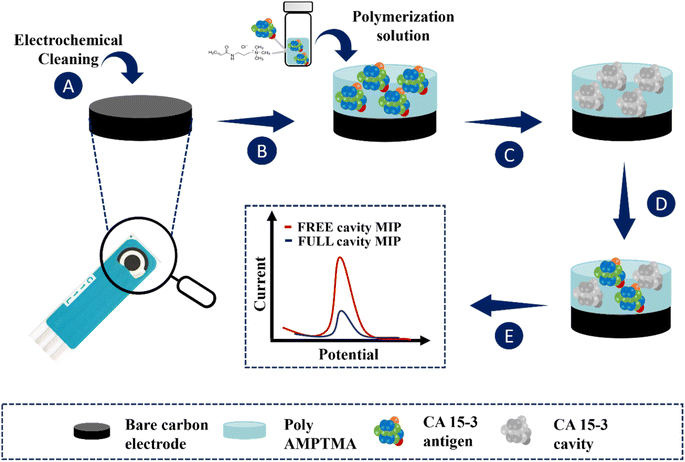
The application of the MIP film to the working electrodes of the C-SPEs is shown in Fig. 1. First, the C-SPEs (Fig. 1A) were subjected to electrochemical cleaning using 0.5 mol L−1 H2SO4. The CV scans covered a potential range from −0.2 to +1.5 V at a scan rate of 0.05 V s−1 for 10 cycles. This step is crucial as it facilitates activation and uniformity of the working range across different electrodes.41,42 Subsequently, 5 μL of the polymerization solution, consisting of 50 mmol L−1 AMPTMA monomer and 100 U mL−1 CA 15-3 (as target molecule), prepared in PB buffer pH 5.8, was applied to the surface of the pretreated working electrode (WE) (Fig. 1B). ELP was performed by CV in a potential range of −0.4 to +0.7 V with a potential scan rate of 0.05 V s−1 for ten consecutive cycles. Finally, the target molecule was removed by incubating 5 μL of a solution containing 500 μg mL−1 proteinase K on the WE overnight at 4 °C (Fig. 1C).Non-imprinted polymers (NIPs) are generated following the same procedure as imprinted polymers, but without including the target molecule in the ELP solution. These NIPs act as references in protein recognition experiments. They are crucial as negative controls in imprinted polymer research, allowing comparison with MIPs to evaluate selectivity. Additionally, NIPs are useful for investigating non-specific interactions between polymers and other molecules, providing a reference point to distinguish specific and non-specific effects, thereby contributing to understanding the properties and performance of imprinted polymers.
3. Results and discussion
3.1. Fabrication of the biosensor
In this work, we developed an electrochemical biosensor that uses a molecularly imprinted polymer to detect the tumor marker CA 15-3 in PoC tests. The ELP of AMPTMA is possible due to the presence of reactive functional groups in the monomer and the application of an electrical potential.43,44ELP is a technique in which an electric current is used to initiate and drive the polymerization of monomers, resulting in the formation of a polymer film on an electrode surface. Here are some key factors that contribute to the ELP of AMPTMA: (i) reactivity of the double bond: AMPTMA contains an acrylamide group that has a reactive double bond (C![[double bond, length as m-dash]](https://www.rsc.org/images/entities/char_e001.gif) C). This double bond is susceptible to polymerization reactions, especially under the influence of an external electric field, and (ii) cationic nature: the presence of a trimethylammonium group in AMPTMA introduces a cationic charge. The cationic character increases the reactivity of the monomer and can facilitate the electrochemical initiation of polymerization.
C). This double bond is susceptible to polymerization reactions, especially under the influence of an external electric field, and (ii) cationic nature: the presence of a trimethylammonium group in AMPTMA introduces a cationic charge. The cationic character increases the reactivity of the monomer and can facilitate the electrochemical initiation of polymerization.
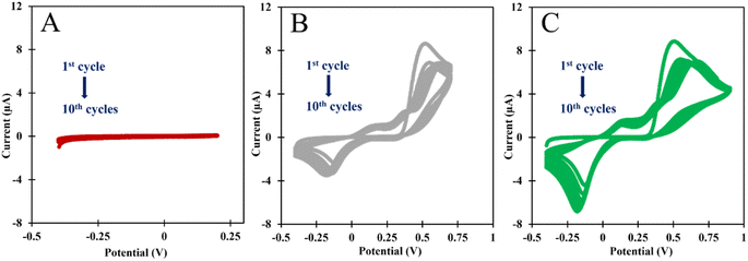 | ||
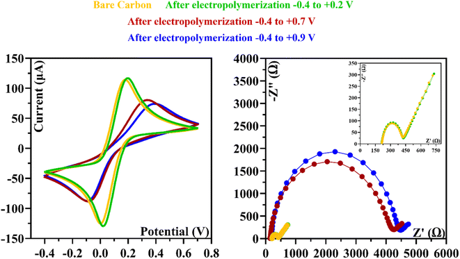
| Fig. 2 CVs of the ELP of the AMPTMA with different range potential. (A) −0.4 to +0.2 V; (B) −0.4 to +0.7 V; and (C) −0.4 to +0.9 V. | ||
In the Fig. 2C, we analyzed the potential effect ranging from −0.4 to +0.9 V. The results are quite similar to those in Fig. 2B, and it appears that an insulating polymer has formed in the C-SPE surface. As for the stability of the sensor surface when the electrodes were exposed to a potential range between −0.4 and +0.7 V, a stable result was obtained in EIS and CV measurements after successive incubations with the buffer solution and measurements with the redox probe. The potential window of ELP selected for further studies was based on the values (I) and charge transfer resistance (RCT) of the analytical reaction and peak separation in CV measurements after successive incubations in PB buffer for 20 min. Since the polymer in the last condition exhibits higher isolation behavior, higher peak separation, and higher RCT value, which hinders the electron charge exchange between the electrode surface and the solution, and consequently, could affect the sensitivity of the sensor (Fig. 3), we chose the potential range between −0.4 and +0.7 V for further studies.
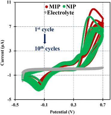
In this research the ELP of AMPTMA was produced by successive CV cycles on the pre-treated C-SPE surface. In the first cycle, the current increased towards the oxidation potentials and showed a peak current at about 0.5 and 0.6 V for NIP and MIP, respectively. This peak indicated the oxidation of AMPTMA and allowed the formation of the polymer (Fig. 4). The subsequent CV cycles showed a continuous decrease in the current of the system, confirming the growth of a non-conducting layer. When the electrode is exposed to a CV scan with buffer only, the peaks remain absent as expected.
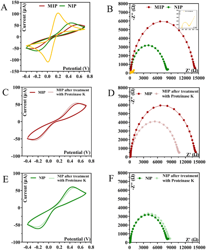
CA 15-3 is removed from the polymer matrix to keep the cavities in shape when exposed to the proteinase K solution. The removal of the protein altered the typical electrical properties of the redox probe as this additional element was no longer present on the surface. After the removal of the template, the current in the CV spectra increased, indicating that the protein was removed from the polymer matrix.
The EIS measurements are consistent with the CV analysis. After ELP, a huge increase in RCT was observed, which increased the diameter of the semicircle (Fig. 5D–F). For MIP material, the RCT is higher than for NIP material, which is expected when the protein is present in MIP. The RCT is different for MIPs and NIPs after exposure to proteinase K (Fig. 5D–F). When the NIP material was exposed to proteinase K, the RCT value of the iron redox probe did not decrease, but only a slight change was observed. In contrast, the RCT value of the MIP material decreased by 25% after exposure to proteinase K.
3.2. Physicochemical characterization of the surface modification
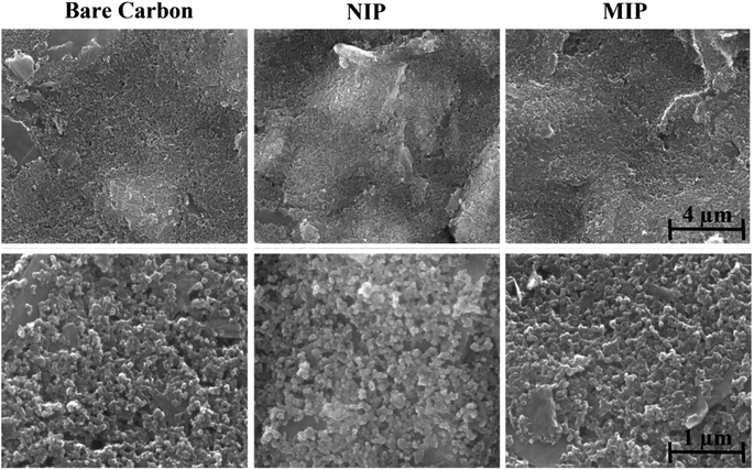
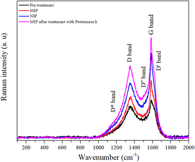
Analyses of morphological and chemical characteristics were carried out on (bio)mimetic materials and control films using scanning electron microscopy (SEM) and Raman spectroscopy.The peak at about 1356 cm−1 is referred to as the disorder-induced or D band and is associated with the A1g symmetry breathing mode, which is associated with the oxidation of graphite and subsequent reduction of graphene oxide and significantly alters the basal plane structure of graphene.47
The degree of graphitization of a carbon material is generally characterized by the ID/IG value in the Raman spectra, where IG is the intensity of the G band corresponding to graphite and ID is the intensity of the D band corresponding to defects and disorder in the graphene oxide. Table S1† shows the variation of the intensities and the relationship between the D and G bands. After a thorough analysis, it is important to highlight the increase in the variation of the ID/IG ratio for the pre-treated (ID/IG = 0.90), MIP (ID/IG = 1.00), and NIP (ID/IG = 0.86) samples, which suggests an increase in the number of defects in the carbon walls. These defects imply that there has been a modification in the working electrode with the polymerization process.48
It appears that the polymer has fewer structural defects than the carbon electrode. This seems surprising considering that graphite is a crystalline form of carbon, with a well-ordered hexagonal lattice structure. However, the electrodes are made of a commercial ink of unknown composition. If we compare the ratio of the NIP with the MIP, this material has fewer defects, which is to be expected since the MIP matrix contains the protein that can cause defects in the polymer. In addition, the ID/IG ratio of the MIP sample decreased after treatment with proteinase K compared to other samples associated with protein extraction due to the presence of cavities in the polymer.
Overall, these results show that the surface of the carbon electrode was modified.
3.3. Analytical performance of the biosensor
Calibration of the MIP was expressed as current response (μA) = 0.0309 × [log(C), CA 15-3] + 0.1588 with a squared correlation coefficient of 0.9942 and a standard deviation on repeated testing 11%. Identical procedures were performed on non-imprinted biosensors (NIP) (Fig. S1†) which showed non-linear behavior. This indicates that within the concentration range studied, the response of the MIP is controlled by the interaction of CA 15-3 with the rebinding sites capable of discriminating the protein.
Furthermore, as far as we are aware, there are no studies in the literature on the detection of CA15-3 using a quaternary ammonium salt as a monomer. However, was reported in the literature some MIP-based sensors use other monomers. The results obtained emphasize the relevance of the comparison between the linearity range and the limit of detection (LOD) reported in the literature using MIP sensors for the determination of CA 15-3 and the results of this study, as can be seen in Table S2†. Compared to other methods, this work showed the best LOD, which allowed quantification of CA 15-3 down to 0.909 mU mL−1. This value is considerably below the threshold required for clinical assessment of breast cancer progression and recurrence, namely 30 U mL−1.
A possible explanation could be the fact that a monomer based on a quaternary ammonium salt, such as AMPTMA, can increase the sensitivity of an MIP sensor due to its unique properties. It forms strong and specific bonds with the target analytes due to the quaternary ammonium group, promotes electrostatic interactions, and increases reactivity during polymerization. This leads to greater efficiency in the formation of molecular recognition sites and to more stable and durable polymers that are ideal for analytical and biosensor applications.
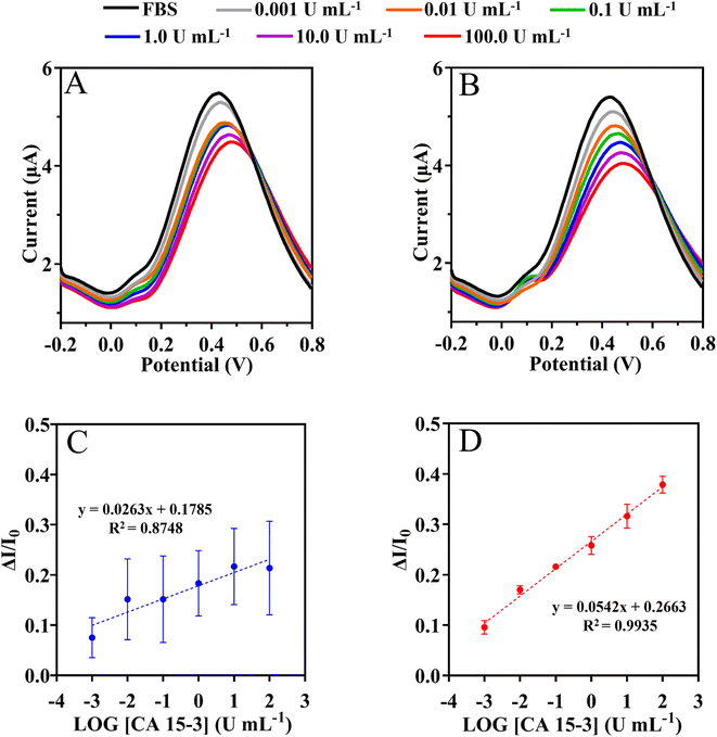
This assay was evaluated with serum 1000-fold diluted in PB buffer, pH 5.8. The SWV and current signals were measured by varying the CA 15-3 concentration within (0.001 and 100 U mL−1), as shown in Fig. 8. The calibration plot was constructed by plotting the current responses (I) against the logarithm of CA 15-3 concentration (Fig. 8). Overall, the peak current at +0.4 V (shift to the right) decreased with increasing protein concentration. Under the optimized conditions, the MIP sensor showed a dynamic response range between 0.001 and 100 U mL−1.
Calibration of the MIP was expressed as current response (μA) = 0.0542 × [log(C), CA 15-3] + 0.2663 with a squared correlation coefficient of 0.9935 and a standard deviation on repeated testing of 4%. Identical procedures were performed on non-imprinted material (NIP) (Fig. 8C), which showed non-linear behavior. Additionally, the NIP material had a lower slope (51% lower than MIP).
Overall, the LLRL of the calibration in buffer and serum is similar within 0.001 U mL−1 and the serum matrix appears to improve the slope by 43%. Overall, these results suggest that it is possible to successfully discriminate the detection of CA 15-3 in complex matrices.
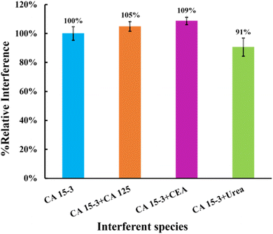 | ||
| Fig. 9 Selectivity studies using a competitive method between the target molecule and the interfering species. The interfering species studied were CEA, CA 125, and urea. | ||
This study showed that the binding of CEA protein (5%), CA 125 protein (9%), and urea (9%) was negligible when competing with the primary compound. These results indicate that the MIP surface has high selectivity, confirming the presence of imprinted cavities for CA 15-3. Consequently, these results suggest that these sensors have the potential to detect CA 15-3 in complex matrices.
4. Conclusions
This study delivered promising results that provide a solid foundation for significant advances in biomarker detection and monitoring, particularly in the context of breast cancer. The use of MIPs in combination with (bio)sensors has shown promise when it comes to the selective and sensitive detection of CA 15-3, a crucial biomarker in this disease. Research has also focused on the evaluation of quaternary ammonium cations as functional monomers for the development of imprinted polymers for protein detection, centered on the CA 15-3 biomarker for breast cancer. The integration of the MIP sensor into real-world applications, such as PoC testing or continuous monitoring of CA 15-3 levels in breast cancer patients, could significantly improve the health management of these patients. The ability to detect quickly and accurately important biomarkers such as CA 15-3 could enable earlier and more targeted intervention, which would have a positive impact on treatment outcomes and thus on patients' quality of life. Furthermore, the prospect of integrating these (bio)sensors into wearable or body-worn devices could revolutionize the way patients monitor their health, enabling an immediate response to fluctuations in biomarker levels and potentially reducing healthcare costs. Thus, this study not only contributes to the advancement of materials science and bioengineering, but also has the potential to make a tangible difference to patients' lives by providing an innovative approach to the diagnosis and monitoring of breast cancer and other health issues.Conflicts of interest
There are no conflicts to declare.Acknowledgements
The authors acknowledge the financial support from the IBEROS + project (Instituto de Biofabricación en Red para el Envejecimiento Saludable), INTERREG POCTEP/0072_IBEROS_MAIS_1_E within the cooperation region of Galicia/Spain and North of Portugal. Additionally, they would like to thank the partial support from the Portuguese Foundation for Science and Technology (FCT), through grants UIDB/04730/2020 and UIDP/04730/2020. Daniela O. acknowledges funding from the Portuguese Foundation for Science and Technology (FCT), I. P., through the PhD grant reference SFRH/BD/137832/2018.References
- H. Chen, K. Liu, Z. Li and P. Wang, Clin. Chim. Acta, 2019, 493, 138–147 CrossRef CAS PubMed.
- S. Shrivastava, T. Q. Trung and N.-E. Lee, Chem. Soc. Rev., 2020, 49, 1812–1866 RSC.
- M. J. Duffy, D. Evoy and E. W. McDermott, Clin. Chim. Acta, 2010, 411, 1869–1874 CrossRef CAS PubMed.
- D. A. Scott and R. R. Drake, Expert Rev. Proteomics, 2019, 16, 665–680 CrossRef CAS PubMed.
- D. Y. Liang, Q. Gao, Z. X. Meng, W. Z. Li, J. Z. Song and K. Xue, Life Sci., 2023, 326, 1–12 CrossRef PubMed.
- R. Beatson, G. Maurstad, G. Picco, A. Arulappu, J. Coleman, H. H. Wandell, H. Clausen, U. Mandel, J. Taylor-Papadimitriou, M. Sletmoen and J. M. Burchell, PLoS One, 2015, 10, 1–21 CrossRef PubMed.
- C. L. Hattrup and S. J. Gendler, Breast Cancer Res., 2006, 8, 1–10 CrossRef PubMed.
- S. Chourin, D. Georgescu, C. Gray, C. Guillemet, A. Loeb, C. Veyret and J. P. Basuyau, Ann. Oncol., 2009, 20, 962–964 CrossRef CAS PubMed.
- A. Nicolini, A. Carpi, P. Ferrari, R. Morganti, V. Mazzotti, V. Barak and M. J. Duffy, Cancer Manage. Res., 2018, 10, 6879–6886 CrossRef.
- L. Zhang, Y. He, H. Wang, Y. Yuan, R. Yuan and Y. Chai, Biosens. Bioelectron., 2015, 74, 924–930 CrossRef CAS PubMed.
- A. Ambrosi, F. Airò and A. Merkoçi, Anal. Chem., 2010, 82, 1151–1156 CrossRef CAS PubMed.
- M. P. Sousa, A. M. L. Piloto, A. C. Pereira, F. C. Schmitt, R. Fernandes and F. T. C. Moreira, Chemosensors, 2022, 10(518), 1–13 Search PubMed.
- P. Li, H. Ye, J. Liu, H. Jin, Y. Lin, S. Yan, Y. Yu, L. Gao, F. Xu and Z. Zhang, J. Clin. Lab. Anal., 2018, 32, e22158 CrossRef.
- C. Zong, J. Wu, C. Wang, H. Ju and F. Yan, Anal. Chem., 2012, 84, 2410–2415 CrossRef CAS.
- J. Huang, T. Zhang, Y. Zheng and J. Liu, Biosensors, 2023, 13, 1–14 Search PubMed.
- Z. Lin, S. Zheng, J. Xie, R. Zhou, Y. Chen and W. Gao, Talanta, 2023, 253, 123912 CrossRef CAS.
- R. C. B. Marques, E. Costa-Rama, S. Viswanathan, H. P. A. Nouws, A. Costa-García, C. Delerue-Matos and M. B. González-García, Sens. Actuators, B, 2018, 255, 918–925 CrossRef CAS.
- T. S. C. R. Rebelo, J. A. Ribeiro, M. G. F. Sales and C. M. Pereira, Sens. Bio-Sens. Res., 2021, 33, 100445 CrossRef.
- M. J. Whitcombe, I. Chianella, L. Larcombe, S. A. Piletsky, J. Noble, R. Porter and A. Horgan, Chem. Soc. Rev., 2011, 40, 1547–1571 RSC.
- M. F. Frasco, L. Truta, M. G. F. Sales and F. T. C. Moreira, Sensors, 2017, 17, 1–29 CrossRef PubMed.
- L. Chen, X. Wang, W. Lu, X. Wu and J. Li, Chem. Soc. Rev., 2016, 45, 2137–2211 RSC.
- U. Akiba and J.-i. Anzai, Sensors, 2016, 16, 2045 CrossRef PubMed.
- J. Kalecki, Z. Iskierko, M. Cieplak and P. S. Sharma, ACS Sens., 2020, 5, 3710–3720 CrossRef CAS PubMed.
- W. Boonsriwong, S. Chunta, N. Thepsimanon, S. Singsanan and P. A. Lieberzeit, Polymers, 2021, 13, 1763 CrossRef CAS PubMed.
- M. Carvalho, R. M. Gomes, S. Moreira Rocha, J. Barroca-Ferreira, C. J. Maia, L. Guillade, M. A. Correa-Duarte, L. A. Passarinha and F. T. C. Moreira, Bioelectrochemistry, 2023, 152, 108461 CrossRef CAS PubMed.
- B. Correia, D. Oliveira, G. Vulpe, A. P. M. Tavares, M. G. F. Sales, A. J. Duarte, S. Sharma and F. T. C. Moreira, Sens. Diagn., 2023, 2, 956–963 RSC.
- J. J. BelBruno, Chem. Rev., 2019, 119, 94–119 CrossRef CAS PubMed.
- R. S. Gomes, F. T. C. Moreira, R. Fernandes and M. G. F. Sales, PLoS One, 2018, 13, e0196656 CrossRef PubMed.
- J. G. Pacheco, M. S. V. Silva, M. Freitas, H. P. A. Nouws and C. Delerue-Matos, Sens. Actuators, B, 2018, 256, 905–912 CrossRef CAS.
- J. A. Ribeiro, C. M. Pereira, A. F. Silva and M. G. F. Sales, Biosens. Bioelectron., 2018, 109, 246–254 CrossRef CAS PubMed.
- A. E. F. Oliveira, A. C. Pereira and L. F. Ferreira, Talanta, 2023, 252, 123819 CrossRef CAS PubMed.
- M. C. C. G. Carneiro, L. R. Rodrigues, F. Moreira and M. G. F. Sales, Microchem. J., 2024, 196, 109640 CrossRef.
- K. Ramajayam, S. Ganesan, P. Ramesh, M. Beena, T. Kokulnathan and A. Palaniappan, Biomimetics, 2023, 8, 1–33 CrossRef.
- L. Moreira Gonçalves, Curr. Opin. Electrochem., 2021, 25, 100640 CrossRef.
- E. Mazzotta, R. A. Picca, C. Malitesta, S. A. Piletsky and E. V. Piletska, Biosens. Bioelectron., 2008, 23, 1152–1156 CrossRef CAS PubMed.
- P. S. Sharma, A. Pietrzyk-Le, F. D'Souza and W. Kutner, Anal. Bioanal. Chem., 2012, 402, 3177–3204 CrossRef CAS PubMed.
- M. Zarejousheghani, A. Jaafar, H. Wollmerstaedt, P. Rahimi, H. Borsdorf, S. Zimmermann and Y. Joseph, Sensors, 2021, 21, 296 CrossRef CAS PubMed.
- H. Xiong, Y. Wan, Y. Fan, M. Xu, A. Yan, Y. Zhang, Q. Jiang and H. Wan, Chin. Chem. Lett., 2024, 35, 108382 CrossRef CAS.
- Z. Liu, Y. Wang, F. Xu, X. Wei, J. Chen, H. Li, X. He and Y. Zhou, Anal. Chim. Acta, 2020, 1129, 49–59 CrossRef CAS PubMed.
- B. Pluhar, U. Ziener and B. Mizaikoff, J. Mater. Chem. B, 2015, 3, 6248–6254 RSC.
- D. Stan, A.-C. Mirica, R. Iosub, D. Stan, N. B. Mincu, M. Gheorghe, M. Avram, B. Adiaconita, G. Craciun and A. L. Bocancia Mateescu, Processes, 2022, 10, 723 CrossRef CAS.
- A. Rana, N. Baig and T. A. Saleh, J. Electroanal. Chem., 2019, 833, 313–332 CrossRef CAS.
- W. Jaeger, J. Bohrisch and A. Laschewsky, Prog. Polym. Sci., 2010, 35, 511–577 CrossRef CAS.
- T. Y. Lin, M. H. Chen and T. C. Chou, J. Appl. Polym. Sci., 2001, 82, 1071–1076 CrossRef CAS.
- O. Beyssac and M. Lazzeri, EMU Notes in Mineralogy, 2012, vol. 12, pp. 415–454 Search PubMed.
- Y. Castano-Guerrero, Y. Romaguera-Barcelay, F. T. C. Moreira, W. R. Brito, E. Fortunato and M. G. F. Sales, Chemosensors, 2022, 10, 1–14 CrossRef.
- D. López-Díaz, M. L. Holgado, J. L. García-Fierro and M. M. Velázquez, J. Phys. Chem. C, 2017, 121, 20489–20497 CrossRef.
- M. Kwiatkowska, R. Pelech, A. Jedrzejewska, D. Moszynski and I. Pelech, Polymers, 2020, 12, 1–20 Search PubMed.
Footnote |
| † Electronic supplementary information (ESI) available. See DOI: https://doi.org/10.1039/d4ra02051k |
| This journal is © The Royal Society of Chemistry 2024 |

