 Open Access Article
Selective hydrogenolysis of 5-hydroxymethylfurfural to 2,5-dimethylfuran with high yield over bimetallic Ru–Co/AC catalysts†
Zhen Dong,
Yahui Zhang and
Haian Xia *
*
Jiangsu Provincial Key Lab for the Chemistry and Utilization of Agro-forest Biomass, College of Chemical Engineering, Nanjing Forestry University, Nanjing, China. E-mail: haxia@njfu.edu.cn; Tel: +86-25-85427635
First published on 8th May 2024
Abstract
Catalytic hydrogenolysis of 5-hydroxymethylfurfural (HMF) to 2,5-dimethylfuran (DMF) has become a hot topic in the bioenergy field in recent years. It remains a challenge to mediate the activation/hydrogenation/hydrogenolysis of C–O and C![[double bond, length as m-dash]](https://www.rsc.org/images/entities/char_e001.gif) O bonds of HMF at high temperatures. Herein, bimetallic Ru–Co/AC catalysts were prepared by the “two-step” reduction method and were used to catalyze the hydrogenolysis of HMF to DMF. The effects of different reduction methods, Ru/Co ratios, and Ru loading on the catalytic performances of the Ru–Co/AC catalysts were investigated, and the physicochemical properties of the catalysts were characterized by TEM, XPS, H2-TPR, etc. It was found that the catalysts reduced by the “two-step” reduction method exhibited better catalytic activities than those fabricated by a single H2 or NaBH4 reduction method. The introduction of Co metals promoted the dispersion of Ru nanoparticles (NPs) on AC and the transfer of electrons from Co to Ru, thereby improving the catalytic activity. An excellent yield of DMF up to 97.9% and 98.7% conversion of HMF were achieved in a short time (1.5 h) under the optimal conditions (200 °C, 1 MPa). Furthermore, the possible reaction pathway for the hydrogenolysis of HMF to DMF over 5%Ru–1%Co/AC catalyst is also discussed. The work shows that the Ru–Co/AC catalysts have great potentials for the conversion of HMF into liquid fuel DMF.
O bonds of HMF at high temperatures. Herein, bimetallic Ru–Co/AC catalysts were prepared by the “two-step” reduction method and were used to catalyze the hydrogenolysis of HMF to DMF. The effects of different reduction methods, Ru/Co ratios, and Ru loading on the catalytic performances of the Ru–Co/AC catalysts were investigated, and the physicochemical properties of the catalysts were characterized by TEM, XPS, H2-TPR, etc. It was found that the catalysts reduced by the “two-step” reduction method exhibited better catalytic activities than those fabricated by a single H2 or NaBH4 reduction method. The introduction of Co metals promoted the dispersion of Ru nanoparticles (NPs) on AC and the transfer of electrons from Co to Ru, thereby improving the catalytic activity. An excellent yield of DMF up to 97.9% and 98.7% conversion of HMF were achieved in a short time (1.5 h) under the optimal conditions (200 °C, 1 MPa). Furthermore, the possible reaction pathway for the hydrogenolysis of HMF to DMF over 5%Ru–1%Co/AC catalyst is also discussed. The work shows that the Ru–Co/AC catalysts have great potentials for the conversion of HMF into liquid fuel DMF.
1. Introduction
The demand for energy is growing rapidly with fast economic development. However, traditional fossil fuels have limited reserves and pose a potential threat to the sustainable development of human society because of environmental pollution by their combustion.1–3 The high-value utilization of biomass has attracted much interest due to its abundant reserves, renewability, and low price.4 Biomass has been used to produce liquid biofuels and high-value chemicals to mitigate environmental pollution, address the energy crisis, and promote sustainable development of human society.5 Therefore, it is very critical to develop biomass energy as an alternative to conventional fossil energy sources.HMF can be produced by dehydration of sugars and cellulose6–8 and has been regarded as one of the top ten bio-platform compounds.9 HMF can be used to synthesize levulinic acid, 2,5-dimethylfuran, 2,5-furan dicarboxylic acid, and other compounds through hydrogenation, oxidation, and other processes.10 DMF, one of the hydrogenolysis products from HMF, has received much attention due to its advantages of high-octane values (high explosion resistance), high energy densities, and low water solubility.1,11 However, HMF possesses various functional groups including C![[double bond, length as m-dash]](https://www.rsc.org/images/entities/char_e001.gif) O, C–O, C
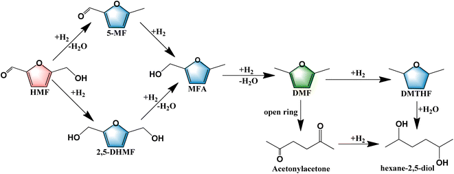
O, C–O, C![[double bond, length as m-dash]](https://www.rsc.org/images/entities/char_e001.gif) C bonds, and furan ring,12,13 which could result in numerous intermediate products and very complex pathways in the hydrogenolysis of HMF. The most common products are summarized in Scheme 1. The dominant pathways are divided into two main ways according to the sequence of hydrogenation of the C
C bonds, and furan ring,12,13 which could result in numerous intermediate products and very complex pathways in the hydrogenolysis of HMF. The most common products are summarized in Scheme 1. The dominant pathways are divided into two main ways according to the sequence of hydrogenation of the C![[double bond, length as m-dash]](https://www.rsc.org/images/entities/char_e001.gif) O bond and the hydrogenolysis of the C–O bond.14 The first pathway involves the formation of DHMF through hydrogenation of the C
O bond and the hydrogenolysis of the C–O bond.14 The first pathway involves the formation of DHMF through hydrogenation of the C![[double bond, length as m-dash]](https://www.rsc.org/images/entities/char_e001.gif) O bond followed by two continuous steps of hydrogenolysis of the C–O bonds. The second pathway involves the hydrogenolysis of the C–O bond before the hydrogenation of the C
O bond followed by two continuous steps of hydrogenolysis of the C–O bonds. The second pathway involves the hydrogenolysis of the C–O bond before the hydrogenation of the C![[double bond, length as m-dash]](https://www.rsc.org/images/entities/char_e001.gif) O bond.15 Both of these pathways involve the same reaction intermediate 5-methyl-2-furanmethanol which possesses a C–O bond, thus the activation of the C–O bond is a key step to increase the yield of DMF.
O bond.15 Both of these pathways involve the same reaction intermediate 5-methyl-2-furanmethanol which possesses a C–O bond, thus the activation of the C–O bond is a key step to increase the yield of DMF.
Up to now, the mono- and bi-metallic catalysts have been applied to the hydrogenolysis of HMF to DMF and satisfactory yields have been obtained,16–18 and the typical catalysts and their catalytic properties are summarized in Table 1. Noble metal-based catalysts have received extensive attraction for their high catalytic activity and high product selectivity under mild conditions.13,19 Priecel et al. used 5 wt% Ru/AC to obtain 96.5% HMF conversion with 83.5% yield of DMF at 150 °C, for 1 h.20 David et al. developed Pd-based catalysts (Pd/Fe2O3) by the co-precipitation method and obtained a 72% yield of DMF at 180 °C and 2.5 MPa.21 The hydrogenation of the furan ring is easier than the C![[double bond, length as m-dash]](https://www.rsc.org/images/entities/char_e001.gif) O bonds over Pd metal sites owing to the narrow d-band of Pd metal and the different bonding modes, resulting in the generation of ring-opening by-products, which is adverse for obtaining a greater selectivity of DMF.22 Non-noble metal-based catalysts have also gained significant interest due to their low cost.23 Yang et al. fabricated Ni-based bimetallic catalysts (Ni–Co/C) using a wet impregnation method and achieved 99% conversion of HMF and 90% yield of DMF using formic acid as the hydrogen source at 210 °C for 24 h.24 Zhang et al. used a co-precipitation method to prepare Cu/Al2O3 catalysts, which afforded a full conversion of HMF with a 73.9% yield of DMF by using formic acid as the hydrogen source at 240 °C for 6 h, attributed to a small Cu particle size and its strong acidic sites.25
O bonds over Pd metal sites owing to the narrow d-band of Pd metal and the different bonding modes, resulting in the generation of ring-opening by-products, which is adverse for obtaining a greater selectivity of DMF.22 Non-noble metal-based catalysts have also gained significant interest due to their low cost.23 Yang et al. fabricated Ni-based bimetallic catalysts (Ni–Co/C) using a wet impregnation method and achieved 99% conversion of HMF and 90% yield of DMF using formic acid as the hydrogen source at 210 °C for 24 h.24 Zhang et al. used a co-precipitation method to prepare Cu/Al2O3 catalysts, which afforded a full conversion of HMF with a 73.9% yield of DMF by using formic acid as the hydrogen source at 240 °C for 6 h, attributed to a small Cu particle size and its strong acidic sites.25
| Catalyst | Temp. (°C) | Pressure of H2 (MPa) | Time (h) | Yield of DMF (%) | Ref. |
|---|---|---|---|---|---|
| Ru/C | 200 | 2 | 2 | 94.7 | 39 |
| Ru/NaY | 220 | 1.5 | 1 | 78.0 | 47 |
| Ru/RuO2/C | 190 | — | 6 | 72.0 | 58 |
| Ru/Co3O4 | 130 | 0.7 | 24 | 93.4 | 59 |
| Ru-MoOx/C | 180 | 1.5 | 1 | 79.8 | 15 |
| Ru/CoFe-LDO | 180 | 2 | 6 | 98.2 | 60 |
| Pt-FeOx/AC | 180 | 1.5 | 6 | 91.1 | 61 |
| Pd/Fe2O3 | 180 | — | 7.5 | 72.0 | 21 |
| Co3O4 | 170 | 1 | 12 | 83.3 | 41 |
| Ni–Mn/AC | 180 | 2 | 4 | 98.5 | 55 |
| Ni–Co/C | 210 | — | 24 | 90.0 | 24 |
| Ru–Co/AC | 200 | 1 | 1.5 | 97.9 | This work |
To efficiently hydrogenolyze HMF to DMF, it is crucial to selectively hydrogenate/hydrogenolyze the C![[double bond, length as m-dash]](https://www.rsc.org/images/entities/char_e001.gif) O and C–O bonds and to avoid the over-hydrogenation or opening of the furan ring.26 Previous research has shown that monometallic catalysts, especially noble-metal based catalysts, prefer the C–C hydrogenation to C–O bonds,27 thereby resulting in over-hydrogenation. In order to obtain a high yield of DMF, one feasible strategy is to control the activation/hydrogenation/hydrogenolysis of C–O and C
O and C–O bonds and to avoid the over-hydrogenation or opening of the furan ring.26 Previous research has shown that monometallic catalysts, especially noble-metal based catalysts, prefer the C–C hydrogenation to C–O bonds,27 thereby resulting in over-hydrogenation. In order to obtain a high yield of DMF, one feasible strategy is to control the activation/hydrogenation/hydrogenolysis of C–O and C![[double bond, length as m-dash]](https://www.rsc.org/images/entities/char_e001.gif) C bonds on the metal NPs and tune their electronic/geometric properties by introducing the second metal into a monometallic catalyst.28 Furthermore, the acidity of catalysts has been reported to be another important factor for the hydrogenolysis of HMF to DMF because the acid sites profoundly affect the hydrogenolysis of the C–O bond.29 Therefore, the introduction of the second metal with reasonable acidity into monometallic catalysts is a promising strategy to high-effectively hydrogenolyze HMF to DMF.
C bonds on the metal NPs and tune their electronic/geometric properties by introducing the second metal into a monometallic catalyst.28 Furthermore, the acidity of catalysts has been reported to be another important factor for the hydrogenolysis of HMF to DMF because the acid sites profoundly affect the hydrogenolysis of the C–O bond.29 Therefore, the introduction of the second metal with reasonable acidity into monometallic catalysts is a promising strategy to high-effectively hydrogenolyze HMF to DMF.
Ru-based catalysts are one of the most popular noble metal-based catalysts because of their excellent catalytic activities in many hydrogenation/hydrogenolysis reactions.30 Generally, Ru metal has high selectivity for hydrogenation of the C![[double bond, length as m-dash]](https://www.rsc.org/images/entities/char_e001.gif) O bond due to its wide d-band,31 which could be favorable for the transformation of HMF to DMF. However, monometallic Ru catalysts have a strong hydrogenation activity and are prone to excessive hydrogenation or opening of the furan ring of DMF.32 For instance, 5%Ru/C was found to afford over-hydrogenation products of HMF, DMTHF and DHMTHF, with selectivities of 6.7% and 10.1%, respectively, and 5%Ru–10%MoOx/C was found to afford DMTHF and DHMTHF with selectivities of 3.4% and 0.4%, respectively,15 which proved that bimetallic catalysts can effectively reduce the excessive hydrogenation. Zu et al. used Ru/Co3O4 to obtain a 93.4% yield of DMF at relatively mild conditions for 24 h and prospected that CoOx acts as the adsorption metal sites of hydrogenation products and then breaks the C–O bond.33 Wang et al. synthesized CuCo/CeOx by a co-precipitation method for catalytic transfer hydrogenation (CTH) of HMF to DMF, and a 95.4% yield of DMF was obtained at 170 °C, and proposed that CuCo bimetallic NPs promoted the cleavage of C–O of DHMF to produce DMF.34 Therefore, it can be prospected that the introduction of Co metal could effectively break the C–O bond and enhance the selectivity of DMF. It is useful to introduce the second metal to enhance the selectivity of DMF.
O bond due to its wide d-band,31 which could be favorable for the transformation of HMF to DMF. However, monometallic Ru catalysts have a strong hydrogenation activity and are prone to excessive hydrogenation or opening of the furan ring of DMF.32 For instance, 5%Ru/C was found to afford over-hydrogenation products of HMF, DMTHF and DHMTHF, with selectivities of 6.7% and 10.1%, respectively, and 5%Ru–10%MoOx/C was found to afford DMTHF and DHMTHF with selectivities of 3.4% and 0.4%, respectively,15 which proved that bimetallic catalysts can effectively reduce the excessive hydrogenation. Zu et al. used Ru/Co3O4 to obtain a 93.4% yield of DMF at relatively mild conditions for 24 h and prospected that CoOx acts as the adsorption metal sites of hydrogenation products and then breaks the C–O bond.33 Wang et al. synthesized CuCo/CeOx by a co-precipitation method for catalytic transfer hydrogenation (CTH) of HMF to DMF, and a 95.4% yield of DMF was obtained at 170 °C, and proposed that CuCo bimetallic NPs promoted the cleavage of C–O of DHMF to produce DMF.34 Therefore, it can be prospected that the introduction of Co metal could effectively break the C–O bond and enhance the selectivity of DMF. It is useful to introduce the second metal to enhance the selectivity of DMF.
It is widely accepted that zero-valent noble metal species are responsible for the dissociation of H2 and serve as the hydrogenation active sites. Chemical reagents and gas reduction are common reduction methods to prepare hydrogenated catalysts.35 Chemical reduction usually involves many reducers such as NaBH4,36 hydrazine hydrate,37 and ethylene glycol, etc. For example, NaBH4 reduction was employed to prepare Ru-based catalysts, which afford excellent catalytic activities due to RuOx being reduced completely and small Ru NPs sizes.38 Gas reduction, such as H2 reduction, can reduce metal oxides into various valence states and alloy catalysts at high temperatures, but high temperatures readily lead to the clustering of small NPs size into larger inactive metal NPs, especially for noble metal catalysts. Low-temperature chemical reduction can give very small metal NP sizes, but it is difficult to reduce transition metal oxides, such as CoOx, and form active alloy sites which are very crucial for some synergetic catalytic reactions in some cases. Therefore, the combined use of both reduction methods is key to prepare catalysts with excellent catalytic properties through controlling small metal NPs sizes and the formation of alloy sites for synergetic catalysis.
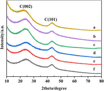
As mentioned above, numerous promising catalysts for the hydrogenolysis of HMF to DMF have been reported, but low reaction temperatures and long reaction times (>12 h) are required in order to obtain high DMF yield and selectivity. So, novel catalysts with high selectivity at high temperatures for the hydrogenolysis of HMF to produce DMF in a short time are still to be explored. Herein, Ru–Co/AC bimetallic catalysts were prepared by a simple wet impregnation method, and Ru and Co metals were cascade reduced by NaBH4 and H2 gas reduction. The effect of different reaction conditions on the hydrogenolysis of HMF to DMF was studied. In addition, the nature of the catalyst was characterized by XRD, TEM, TPR, XPS, etc. The synergistic effect between Ru and Co species was elucidated and the deactivation reason of the catalysts was explained.
2. Experimental
2.1 Catalyst preparation
The bimetallic Ru–Co/AC catalysts were synthesized by the wet impregnation method. A typical prepared procedure of the Ru–Co/AC catalyst was described as follows. First, an appropriate amount of activated carbon (AC, SBET = 1693.5 m2 g−1, Table S1†) was added into ultra-pure water, and then the desired mass of RuCl3·xH2O was dissolved into 0.2 mol L−1 HCl solution. Subsequently, the RuCl3 solution was drop by drop added to the aqueous-AC mixed solution with stirring by a constant-flow pump, and then the mixture was stirred for 12 h. Next, the 0.1 mol L−1 NaBH4 solution was added dropwise to the impregnation Ru/AC solution in an ice water bath under vigorous stirring. After stirring for 4 h at room temperature, the mixture was filtered and washed with ultra-pure water. The second step is to incorporate Co onto the AC as follows, desired amounts of Co (NO3)2·6H2O were dissolved into ultra-pure water and then added to the Ru/AC suspension solution. After 12 hours, the mixture was filtered, washed, and dried at 60 °C for 12 hours. Finally, the catalyst precursor was calcined in a flow of 5.0 vol.%H2/N2 flow at 300 °C for 2 h. Similarly, the Ru–Re/AC and Ru–Mo/AC catalysts were prepared through the wet impregnation method, only Co (NO3)2·6H2O was replaced by NH4ReO4 and (NH4)6Mo7O24·4H2O, respectively. For comparison, the monometallic Ru/AC or Co/AC were also fabricated by a similar method. The resulting bimetallic catalysts were denoted as x%Ru–y%M/AC (M = Co, Re, and Mo), where x and y refer to the corresponding metal loadings. The elemental contents of the catalysts analyzed by ICP-AES are listed in Table S2.† As can be seen, the final Ru and Co loadings of the as-prepared catalysts roughly match the Ru and Co precursor contents.2.2 Catalytic performances
The catalytic performances were evaluated by a stainless-steel high-pressure autoclave (50 mL) equipped with mechanical stirring. The catalyst (25 mg), HMF (1.25 wt% relative to THF), and THF (20 mL) were added to the autoclave and then it was sealed followed by flushing with N2 and H2 three times respectively to remove air. Then, the autoclave was pressurized with a desired H2, heated to the target temperature reacted at the set time. The reaction products were analyzed by a Shimadzu LC-2050 equipped with a UV detector. A mobile phase was composed of 60% methanol and 40% pure water at a flow rate of 1 mL min−1, and a C18 column was used for product separation with UV wavelengths of 284 nm (HMF) and 219 nm (DMF). HMF and DMF were quantified based on the external standard method. The conversion of HMF and yield and selectivity of DMF was calculated using the following equations:2.3 Catalysts characterization
X-ray diffraction patterns (XRD) were obtained with a Rigaku Ultima IV X-ray diffractometer (Rigaku, Matsubara Cho, Japan) equipped with a Cu Kα X-ray source operating at 40 kV and 30 mA. X-ray photoelectron spectra (XPS) were recorded on a KRATOS AXIS Ultra DLD instrument (Shimadzu, Tokyo, Japan). Transmission electron microscope (TEM) image was carried out with a JEM-200CX transmission electron microscope (JEOL, Tokyo, Japan). Elemental analysis was performed with an icpmsPE300D inductively coupled plasma atomic emission spectrometer (ICP-AES). The specific surface area was measured by N2 isothermal adsorption on BSD-PM2. The samples were outgassed at 120 °C for 5 h before analysis. Temperature programmed reduction (TPR) was undertaken on BELCAT-A equipped with a TCD detector to measure the reduction behaviors of the catalysts. For H2-TPR experiments, the 50 mg sample was heated to 800 °C at the rate of 10 °C min−1, after being cooled to room temperature, 5 vol.% H2/N2 gas was used as the reduced gas. Temperature programmed desorption of NH3 (NH3-TPD) was conducted on BELCAT-A to analyze the amount of acid sites of the catalysts. 50 mg sample was purged by He at 400 °C before adsorption, then cooled to 100 °C to saturate with NH3 and swept by He to remove the physically adsorbed NH3 for 0.5 h, and then the samples were heated to 400 °C at the rate of 10 °C min−1.3. Results and discussion
3.1 The nature of the catalysts
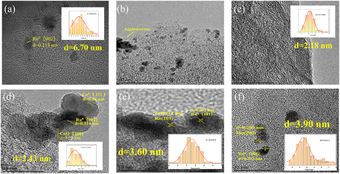 | ||
| Fig. 2 TEM images of (a, b) 5%Ru/AC catalyst, (c) 1%Co/AC, (d) 5%Ru–1%Co/AC, (e) 5%Ru–1% Re/AC, and (f) 5%Ru–1%Mo/AC. | ||
| Entry | Catalyst | Conv. (%) | Yield (%) | Sel. (%) |
|---|---|---|---|---|
| a Reaction conditions: catalyst, 25 mg, HMF, 1.25 wt% relative to THF; THF, 20 mL. 200 °C, 1 MPa, 1.5 h.b Ru was reduced by NaBH4 and Co was reduced at 300 °C for 2 h.c Ru and Co were reduced by H2 at 300 °C for 2 h.d Ru and Co were reduced by NaBH4.e Ru was reduced by NaBH4 and Co was reduced at 400 °C for 2 h.f Ru was reduced by NaBH4 and Co was reduced at 200 °C for 2 h. | ||||
| 1b | 5%Ru–1%Co/AC | 98.7 | 97.9 | 99.2 |
| 2c | 5%Ru–1%Co/AC-C-300 | 74.0 | 52.6 | 71.2 |
| 3d | 5%Ru–1%Co/AC-C-NaBH4 | 98.5 | 89.7 | 91.1 |
| 4e | 5%Ru–1%Co/AC-400 | 98.6 | 92.9 | 94.2 |
| 5f | 5%Ru–1%Co/AC-200 | 98 | 93.4 | 94.7 |
To explore the reason for the better catalytic performance of 5%Ru–1%Co/AC than that of 5%Ru–1%Re/AC and 5%Ru–1%Mo/AC, we also characterized 5%Ru–1%Re/AC and 5%Ru–1%Mo/AC by TEM. As shown in Fig. 2e and f, the average particle sizes of 5%Ru–1%Re/AC and 5%Ru–1%Mo/AC are about 3.60 and 3.90 nm respectively, which is slightly larger than that of 5%Ru–1%Co/AC. We can also observe the slight agglomeration of Ru NPs on 5%Ru–1%Re/AC and 5%Ru–1%Mo/AC (Fig. S2h and 2i), which shows that the dispersion of particles on 5%Ru–1%Re/AC and 5%Ru–1%Mo/AC is inferior than that on 5%Ru–1%Co/AC. According to the results above, we speculate that the reason that the Ru NPs particle size of 5%Ru–1%Co/AC is smaller and has higher dispersion compared to the other catalysts. In other words, the interactions between Ru and Co species could be stronger.
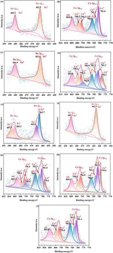
As shown in Fig. 3e, for the 5%Ru–1%Co/AC-C-300 catalyst (Ru and Co were reduced by H2 at 300 °C for 2 h), the peaks of Ru0 and Run+ are observed, indicating that Ru3+ was incompletely reduced and the oxidation state of Ru (Run+) and the zero-valence state of Ru (Ru0) co-existed in the 5%Ru–1%Co/AC-C-300 catalyst, resulting in insufficient of active hydrogenation sites on the catalyst. As shown in Fig. 3f and g, for the 5%Ru–1%Co/AC-C-NaBH4 catalyst (Ru and Co were reduced by NaBH4), the binding energies of Ru and Co species of the 5%Ru–1%Co/AC C–NaBH4 catalyst were not shifted obviously compared to the 5%Ru/AC and 1%Co/AC catalysts, indicating that there is little or no electron transfer between Ru and Co species and the synergistic effect between Ru and Co species is extremely weak. As illustrated in Fig. 3h and i, for the 5%Ru–1%Co/AC-400 catalyst (Ru was reduced by NaBH4 and Co was reduced at 400 °C for 2 h), a larger Co metal peak appears with a binding energy of 778.3 eV, which can be explained by the fact that more Co2+ was reduced into Co metal at 400 °C. For the 5%Ru–1%Co/AC-200 catalyst (Ru was reduced by NaBH4 and Co was reduced at 200 °C for 2 h), no obvious Co metal peak appears because Co2+ is hard to be reduced to Co metal at this reduction temperature.
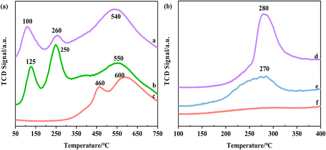 | ||
| Fig. 4 The H2-TPR profile of (a) 5%Ru–1%Co/AC, (b) 5%Ru/AC, (c) 1%Co/AC and TheNH3-TPD profile of (d) 1%Co/AC, (e) 5%Ru–1%Co/AC, (f) 5%Ru/AC. | ||
The acid sites of the catalysts were analyzed by NH3-TPD, as shown in Fig. 4b. Almost no peak was observed over the 5%Ru/AC catalyst, indicating that the monometallic catalyst almost had no acidity. And for the 1%Co/AC catalyst, there was an obvious peak at 280 °C, indicating that the catalyst possesses medium acidic sites.53 After the incorporation of Co species, a peak at about 280 °C was observed over the 5%Ru–1%Co/AC catalyst, which showed that the addition of Co species endows the acidic sites of the bimetallic catalyst.
3.2 Hydrogenolysis of HMF to DMF
| Entry | Catalyst | Conv. (%) | Yield (%) | Sel. (%) |
|---|---|---|---|---|
| a Reaction conditions: catalyst, 25 mg; HMF, 1.25 wt% relative to THF; THF, 20 mL.200 °C, 1 MPa, 1.5 h.b Reaction conditions: catalyst, 50 mg; HMF, 2.5 wt% relative to THF; THF, 20 mL. 200 °C,1 MPa, 1.5 h. | ||||
| 1a | 5%Ru/AC | 93.8 | 74.5 | 79.4 |
| 2a | 1%Co/AC | 42.2 | 21.3 | 50.4 |
| 3a | 5%Ru/AC + 1%Co/AC | 95.7 | 81.3 | 85.0 |
| 4b | 5%Ru–1%Co/AC | 99.3 | 85.9 | 86.6 |
| 5b | 5%Ru–1%Re/AC | 99.3 | 82.6 | 83.2 |
| 6b | 5%Ru–1%Mo/AC | 99.3 | 81.3 | 81.9 |
Meanwhile, we prepared 5%Ru/AC and 1%Co/AC catalysts to compare their catalytic performances, as shown in Table 3. It can be seen that the 5%Ru–1%Co/AC catalyst outperformed both the monometallic 5%Ru/AC and 1%Co/AC catalysts in the hydrogenolysis of HMF. It is worth noting that some ring-opening products of DMF were detected over 5%Ru/AC by GC-MS (Fig. S2†), which verifies that the monometallic Ru catalysts are prone to excessive hydrogenation or ring-opening reactions. To confirm the synergistic effect between Ru and Co species, we physically mixed 5%Ru/AC and 1%Co/AC and then used them for the hydrogenolysis of HMF (Table 3, entry 3), and found that the yield of DMF was much lower than that of 5%Ru–1%Co/AC. This suggests that the synergistic effect between Ru and Co species enhanced the catalytic activity of the 5%Ru–1%Co/AC catalyst.
| Entry | Catalyst | Conv. (%) | Yield (%) | Sel. (%) |
|---|---|---|---|---|
| a Reaction conditions: catalyst, 25 mg, HMF, 1.25 wt% relative to THF; THF, 20 mL. 200 °C, 1 MPa, 1.5 h. | ||||
| 1 | 2.5%Ru–1%Co/AC | 83.0 | 70.6 | 85.1 |
| 2 | 5%Ru–0.5%Co/AC | 98.6 | 96.7 | 98.0 |
| 3 | 5%Ru–1%Co/AC | 98.7 | 97.9 | 99.2 |
| 4 | 5%Ru–5%Co/AC | 98.7 | 95.8 | 97.1 |
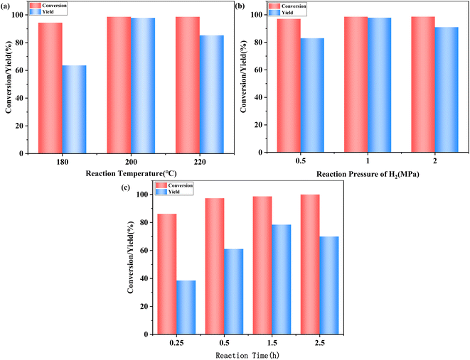
At a lower pressure of 0.5 MPa, the hydrogenolysis of HMF was incomplete, producing numerous intermediates, and resulting in a low yield of DMF. When H2 pressure was increased to 1 MPa, a 97.9% yield of DMF was achieved, which could be explained by the increase of H2 pressure promoting the dissolution of H2 in THF. When the pressure of H2 was increased to 2 MPa, excessive H2 pressure resulted in the production of by-products and a decrease in the yield of DMF.
Fig. 5c shows the influence of reaction time on the hydrogenolysis of HMF. As can be seen, 97.4% conversion of HMF and 76.0% yield of DMF were obtained within 0.5 hours. When the reaction time was extended to 1.5 hours, the conversion of HMF did not increase, but the enhancement in yield of DMF was more significant, perhaps because extending the time further promoted the conversion of intermediates to DMF. When further extended to 2.5 hours, the yield of DMF decreased. This suggests that DMF may be converted into more undesirable by-products if excessive reaction time is employed.
Based on the above-mentioned results and the previously reported literature,39,55–57 we speculate that the following reaction pathway for the hydrogenolysis of HMF to DMF over 5%Ru–1%Co/AC. Firstly, CoOx species on the catalyst surface bound the oxygen atom of the C–O group in HMF, and the cleavage of the C–O bond occurred under the synergistic effects of Ru0 and CoOx species to form the 5-MF. Next, MFA was formed from the hydrogenation of 5-MF by Ru NPs. Finally, the target product DMF was obtained from the hydrogenolysis of MFA via a similar reaction pathway as the hydrogenolysis of HMF to 5-MF.
4. Conclusions
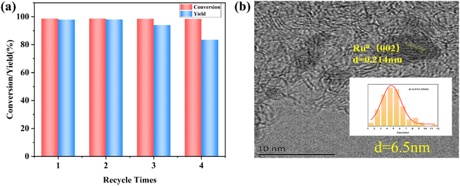
In this work, bi-functional Ru–Co/AC catalysts were prepared by the “two-step” reduction method, which can efficiently convert HMF to DMF. It was revealed that the introduction of Co species decreased the average particle size of Ru NPs, which promoted the catalytic hydrogenolysis of HMF of the Ru–Co/AC catalysts. In addition, it was found that the highest DMF yield of 5%Ru–1%Co/AC could be achieved by first reducing Ru by NaBH4 followed by impregnating with Co, and finally reducing it by H2. An excellent yield of up to DMF 97.9% with the HMF conversion of 98.7% was achieved in a short period (1.5 h). Ru NPs act as an active hydrogenation site and CoOx serves as the acid site to synergistically activate and crack the C–O bonds during the hydrogenolysis reaction of HMF. The synergistic effect between Ru and Co NPs improves the selective hydrogenolysis of HMF to DMF. Moreover, the catalyst has good recyclability and could be reused at least 3 times without a significant loss in activity, and the slight deactivation was attributed to the increase in particle sizes and the leaching of the active metal. This work demonstrates that the Ru–Co/AC catalysts have great potential for the high-efficiency transformation of bio-platform molecules to biofuels.Author contributions
Zhen Dong: conceptualization, formal analysis, investigation, resources, writing original draft, visualization. Yahui Zhang: data summary and calibration. Haian Xia: writing review and editing, funding acquisition.Conflicts of interest
The authors declare that they have no known competing financial interests or personal relationships that could have appeared to influence the work reported in this paper.Acknowledgements
This work was financially supported by the Key Research and Development Program of Jiangsu Province (BE2020039), and the National Natural Science Foundation of China (grant no. 32071723).References
- Y. Román-Leshkov, C. J. Barrett, Z. Y. Liu and J. A. Dumesic, Nature, 2007, 447, 982–985 CrossRef PubMed.
- C. G. Yoo and T. H. Kim, Energies, 2020, 13, 5438 CrossRef.
- H. L. Long, X. B. Li, H. Wang and J. D. Jia, Renewable Sustainable Energy Rev., 2013, 26, 344–352 CrossRef.
- L. Hu, L. Lin, Z. Wu, S. Y. Zhou and S. J. Liu, Renewable Sustainable Energy Rev., 2017, 74, 230–257 CrossRef CAS.
- W. W. Zhu, H. M. Yang, J. Z. Chen, C. Chen, L. Guo, H. M. Gan, X. G. Zhao and Z. S. Hou, Green Chem., 2014, 16, 1534–1542 RSC.
- R. Karinen, K. Vilonen and M. Niemelä, ChemSusChem, 2011, 4, 1002–1016 CrossRef CAS PubMed.
- A. A. Rosatella, S. P. Simeonov, R. F. M. Frade and C. A. M. Afonso, Green Chem., 2011, 13, 754–793 RSC.
- R.-J. van Putten, J. C. van der Waal, E. de Jong, C. B. Rasrendra, H. J. Heeres and J. G. de Vries, Chem. Rev., 2013, 113, 1499–1597 CrossRef CAS PubMed.
- G. Yong, Y. G. Zhang and J. Y. Ying, Angew. Chem., Int. Ed., 2008, 47, 9345–9348 CrossRef CAS PubMed.
- J.-P. Lange, W. D. van de Graaf and R. J. Haan, ChemSusChem, 2009, 2, 437–441 CrossRef CAS PubMed.
- R. Insyani, D. Verma, S. M. Kim and J. Kim, Green Chem., 2017, 19, 2482–2490 RSC.
- H. Wang, C. Zhu, D. Li, Q. Liu, J. Tan, C. Wang, C. Cai and L. Ma, Renewable Sustainable Energy Rev., 2019, 103, 227–247 CrossRef CAS.
- Y. Sun, J. Zheng, J. Xu, K. Yang, Z. Zhu, T. Su, H. Ge, W. Ren and H. Lü, Fuel, 2022, 315, 123226 CrossRef CAS.
- H. Son Le, Z. Said, M. Tuan Pham, T. Hieu Le, I. Veza, V. Nhanh Nguyen, B. Deepanraj and L. Huong Nguyen, Fuel, 2022, 324, 124474 CrossRef CAS.
- Y. Yang, Q. Y. Liu, D. Li, J. Tan, Q. Zhang, C. G. Wang and L. L. Ma, RSC Adv., 2017, 7, 16311–16318 RSC.
- D. S. Brands, E. K. Poels and A. Bliek, Appl. Catal., A, 1999, 184, 279–289 CrossRef CAS.
- Y. Takeda, Y. Nakagawa and K. Tomishige, Catal. Sci. Technol., 2012, 2, 2221–2223 RSC.
- J. Zhang, L. Lin and S. Liu, Energy Fuels, 2012, 26, 4560–4567 CrossRef CAS.
- W. T. Lu, J. C. Chen, J. Feng and J. Yu, Rare Met. Mater. Eng., 2012, 41, 184–188 CAS.
- P. Priecel, N. A. Endot, P. D. Carà and J. A. Lopez-Sanchez, Ind. Eng. Chem. Res., 2018, 57, 1991–2002 CrossRef CAS.
- D. Scholz, C. Aellig and I. Hermans, ChemSusChem, 2014, 7, 268–275 CrossRef CAS PubMed.
- S. Sitthisa and D. E. Resasco, Catal. Lett., 2011, 141, 784–791 CrossRef CAS.
- X. C. Zheng, X. Y. Wang, L. H. Yu, S. R. Wang and S. H. Wu, Progr. Chem., 2006, 18, 159–167 CAS.
- P. P. Yang, Q. N. Xia, X. H. Liu and Y. Q. Wang, Fuel, 2017, 187, 159–166 CrossRef CAS.
- Z. H. Zhang, C. X. Wang, X. Gou, H. Chen, K. Q. Chen, X. Y. Lu, P. K. Ouyang and J. Fu, Appl. Catal., A, 2019, 570, 245–250 CrossRef CAS.
- G. H. Wang, J. Hilgert, F. H. Richter, F. Wang, H. J. Bongard, B. Spliethoff, C. Weidenthaler and F. Schüth, Nat. Mater., 2014, 13, 294–301 Search PubMed.
- Q. Wang, S. Santos, C. A. Urbina-Blanco, W. Zhou, Y. Yang, M. Marinova, S. Heyte, T.-R. Joelle, O. Ersen, W. Baaziz, O. V. Safonova, M. Saeys and V. V. Ordomsky, Appl. Catal., B, 2022, 300, 120730 CrossRef CAS.
- Y. Y. Li, R. N. Wang, B. W. Huang, L. L. Zhang, X. R. Ma, S. K. Zhang, Z. G. Zhu, H. Y. Lü and K. X. Yang, Appl. Surf. Sci., 2022, 604, 154579 CrossRef CAS.
- J. Kuljiraseth, A. Wangriya, J. M. C. Malones, W. Klysubun and S. Jitkarnka, Appl. Catal., B, 2019, 243, 415–427 CrossRef CAS.
- M. Chidambaram and A. T. Bell, Green Chem., 2010, 12, 1253–1262 RSC.
- T. W. H. AN, Chem. Ind. Eng. Prog., 2021, 40, 824–834 Search PubMed.
- M. Luneau, J. S. Lim, D. A. Patel, E. C. H. Sykes, C. M. Friend and P. Sautet, Chem. Rev., 2020, 120, 12834–12872 CrossRef CAS PubMed.
- Y. Zu, P. Yang, J. Wang, X. Liu, J. Ren, G. Lu and Y. Wang, Appl. Catal., B, 2014, 146, 244–248 CrossRef CAS.
- X. F. Wang, C. C. Zhang, Z. Y. Zhang and Q. B. Li, Fuel, 2022, 320, 123996 CrossRef CAS.
- A. W. Heinen, J. A. Peters and H. van Bekkum, ChemInform, 2001, 328, 449–457 Search PubMed.
- T. Furusawa, M. Shirasu, K. Sugiyama, T. Sato, N. Itoh and N. Suzuki, Ind. Eng. Chem. Res., 2016, 55, 12742–12749 CrossRef CAS.
- F. T. Jere, J. E. Jackson and D. J. Miller, Ind. Eng. Chem. Res., 2004, 43, 3297–3303 CrossRef CAS.
- T. Shi, Degree Thesis of Master, Zhejiang University of Technology, 2016.
- L. Hu, X. Tang, J. X. Xu, Z. Wu, L. Lin and S. J. Liu, Ind. Eng. Chem. Res., 2014, 53, 3056–3064 CrossRef CAS.
- L. Y. Song, X. H. Li, H. N. Wang, H. H. Wu and P. Wu, Catal. Lett., 2009, 133, 63–69 CrossRef CAS.
- D. Li, Q. Y. Liu, C. H. Zhu, H. Y. Wang, C. H. Cui, C. G. Wang and L. L. Ma, J. Energy Chem., 2019, 30, 34–41 CrossRef.
- Z. Gao, G. L. Fan, M. R. Liu, L. Yang and F. Li, Appl. Catal., B, 2018, 237, 649–659 CrossRef CAS.
- F. B. Noronha, M. Schmal, B. Moraweck, P. Delichère, M. Brun, F. Villain and R. Fréty, J. Phys. Chem. B, 2000, 104, 5478–5485 CrossRef CAS.
- M. Esen, S. Akmaz, S. N. Koc and M. A. Gürkaynak, J. Sol-Gel Sci. Technol., 2019, 91, 664–672 CrossRef CAS.
- C. E. Scott, P. Betancourt, M. J. Pérez Zurita, C. Bolívar and J. Goldwasser, Appl. Catal., A, 2000, 197, 23–29 CrossRef CAS.
- W. Wang, N. Li, S. S. Li, G. Y. Li, F. Chen, X. R. Sheng, A. Q. Wang, X. D. Wang, Y. Cong and T. Zhang, Green Chem., 2016, 18, 1218–1223 RSC.
- A. S. Nagpure, N. Lucas and S. V. Chilukuri, ACS Sustainable Chem. Eng., 2015, 3, 2909–2916 CrossRef CAS.
- S. Z. Zheng, X. Y. Cao, Q. Zhou, S. H. Wang, G. S. Hu, J. Q. Lu, M. F. Luo and Y. J. Wang, J. Fluorine Chem., 2013, 145, 132–135 CrossRef CAS.
- I. Rossetti, N. Pernicone and L. Forni, Appl. Catal., A, 2003, 248, 97–103 CrossRef CAS.
- H.-Y. Lin and Y.-W. Chen, Mater. Chem. Phys., 2004, 85, 171–175 CrossRef CAS.
- S. R. de Miguel, M. C. Román-Martínez, E. L. Jablonski, J. L. G. Fierro, D. Cazorla-Amorós and O. A. Scelza, J. Catal., 1999, 184, 514–525 CrossRef CAS.
- J. Yu, D. Zhao, X. L. Xu, X. Wang and N. Zhang, ChemCatChem, 2012, 4, 1122–1132 CrossRef CAS.
- Y. Chu, T. Zhang, J. Guo, C. Liu, H. Yin, X. Zhu and Y. Liu, J. Rare Earths, 2015, 33, 371–381 CrossRef CAS.
- W. J. Xu, H. F. Wang, X. H. Liu, J. W. Ren, Y. Q. Wang and G. Z. Lu, Chem. Commun., 2011, 47, 3924–3926 RSC.
- Y. X. Liu, X. Y. Shi, J. B. Hu, K. Liu, M. Zeng, Y. X. Hou and Z. J. Wei, ChemSusChem, 2022, 15, e202200193 CrossRef CAS PubMed.
- T. Thananatthanachon and T. B. Rauchfuss, Angew. Chem., Int. Ed., 2010, 49, 6616–6618 CrossRef CAS PubMed.
- J. Jae, W. Q. Zheng, R. F. Lobo and D. G. Vlachos, ChemSusChem, 2013, 6, 1158–1162 CrossRef CAS PubMed.
- P. Panagiotopoulou, N. Martin and D. G. Vlachos, J. Mol. Catal. A: Chem., 2014, 392, 223–228 CrossRef CAS.
- Y. H. Zu, P. P. Yang, J. J. Wang, X. H. Liu, J. W. Ren, G. Z. Lu and Y. Q. Wang, Appl. Catal., B, 2014, 146, 244–248 CrossRef CAS.
- Q. Y. Li, P. Man, L. Q. Yuan, P. L. Zhang, Y. Li and S. Y. Ai, Mol. Catal., 2017, 431, 32–38 CrossRef CAS.
- Y. J. Xin, S. C. Li, H. Y. Wang, L. G. Chen, S. Li and Q. Y. Liu, Catalysts, 2021, 11, 915 CrossRef CAS.
Footnote |
| † Electronic supplementary information (ESI) available. See DOI: https://doi.org/10.1039/d4ra02054e |
| This journal is © The Royal Society of Chemistry 2024 |

