
 Open Access Article
 This Open Access Article is licensed under a Creative Commons Attribution-Non Commercial 3.0 Unported Licence
Hydrophobic modification enhances the microstructure stability of the catalyst layer in alkaline polymer electrolyte fuel cells†
Jun Maa,
Hualong Maa,
Jiayi Lina,
Yixiao Zhanga,
Li Xiao bc,
Lin Zhuangbd,
Pengtao Xu*a and
Liwei Chen*a
bc,
Lin Zhuangbd,
Pengtao Xu*a and
Liwei Chen*a
aSchool of Chemistry and Chemical Engineering, In situ Center for Physical Sciences, Shanghai Electrochemical Energy Device Research Center (SEED), Global Institute of Future Technology, Shanghai Jiao Tong University, Shanghai 200240, China. E-mail: xupengtao@sjtu.edu.cn; lwchen2018@sjtu.edu.cn
bHubei Key Lab of Electrochemical Power Sources, College of Chemistry and Molecular Sciences, Wuhan University, Wuhan 430072, China
cSauvage Center for Molecular Sciences, Wuhan University, Wuhan 430072, China
dThe Institute for Advanced Studies, Wuhan University, Wuhan 430072, China
First published on 23rd August 2024
Abstract
Alkaline polymer electrolyte fuel cells (APEFCs) have achieved notable advancements in peak power density, yet their durability during long-term operation remains a significant challenge. It has been recognized that increasing the hydrophobicity of the catalyst layer can effectively alleviate the performance degradation. However, a microscopic view of how hydrophobicity contributes to the stability of the catalyst layer microstructure is not clear. Here, we construct a membrane electrode assembly (MEA) with enhanced structural stability and durability by incorporating polytetrafluoroethylene (PTFE) particles into the catalyst layer. MEAs modified by this approach exhibit stabilized voltage platforms in current step tests and reduced hysteresis in current–voltage polarization curves during operation, indicating the critical role of PTFE in the removal of the excess water within the catalyst layer. Fuel cells with PTFE modification show more than 45% increase in electrochemical durability. By characterizing with field-emission scanning electron microscopy (FE-SEM) the surface and the internal microstructures of MEAs after durability tests, we find that the catalyst layers modified by PTFE experience much less reduction in porosity and less agglomeration of the solid components. These findings elucidate the microscopic mechanisms by which hydrophobicity promotes a more stable catalyst layer structure, thereby enhancing the durability of APEFCs. This research advances our understanding of hydrophobicity's impact on catalyst layer stability and offers a practical method to enhance the durability of APEFCs.
1 Introduction
Fuel cells are considered efficient and green energy conversion devices suitable for vehicles and portable power generation equipment. Proton exchange membrane fuel cells (PEMFCs) are the most developed type, yet their reliance on costly precious metal catalysts is a significant limitation. Alkaline polymer electrolyte fuel cells (APEFCs) are viewed as an attractive alternative to reduce the cost, due to the diverse selection of low-cost materials, including non-precious metal catalysts and affordable alkaline polymer electrolyte materials.1–4 With recent research advances in high-performance alkaline polymer electrolytes (APEs), the performance of APEFCs has undergone significant improvement. The peak power density of numerous APEFCs has reached 1 W cm−2,5–9 with the maximum being 3.4 W cm−2,10 which is now comparable to that of PEMFCs. However, the limited stability of APEFCs remains a significant challenge for practical application. Most APEFCs exhibit a durability of less than 1000 h,5,11,12 falling short of the target set for light-duty vehicles (5000 h) and stationary application (80![[thin space (1/6-em)]](https://www.rsc.org/images/entities/char_2009.gif) 000 h) by the Department of Energy of the United States.13
000 h) by the Department of Energy of the United States.13
Substantial research efforts have been devoted to understanding the short durability of APEFCs. It has been identified that the primary factors influencing APEFCs' durability include the agglomeration and the migration of catalyst particles,14,15 the degradation and physical aging of ionomers,12,16,17 and the chemical instability of the electrolyte membranes.18,19 Moreover, certain operating conditions, such as the poor regulation of temperature and humidity, are also shown to reduce APEFCs' durability.20,21 For example, for APEFCs based on quaternary ammonia poly(N-methyl-piperidine-co-p-terphenyl) (QAPPT), the degradation of ionomer and the destruction of catalyst layer structures were proved to be the primary factors contributing to the performance degradation, as revealed by previous studies.16,17 The pore structure destruction is attributed to non-uniform mechanical stress generated in the catalyst layer, which may arise from changes in water content.22,23 During fuel cell operation, water content in the membrane electrode assembly (MEA) shows a non-uniform distribution.24,25 The ionomer volume in the catalyst layer is susceptible to changes with water content, which induce local mechanical stress that deteriorates gas and water transport. Structural changes in the catalyst layer due to humidity variations have also been demonstrated. Yin et al.26 observed that the ionomer migrates during humidity changes, particularly at high relative humidity, leading to the destruction of the catalyst layer structure. Chang et al.27 reported that humidity changes render the catalyst layer structure unstable, causing cracks or catalyst agglomeration.
Among various attempts to address the above challenges, hydrophobic modification of the catalyst layers has been shown as an effective method.22,28–30 Peng et al.22 incorporated PTFE particles into both the catalyst layers and gas diffusion layers and found an improved voltage stability of the APEFC. Alternatively, Hu et al.30 modified the catalyst layer's hydrophobic properties by adopting a hydrophobic ionomer and reported a longer cell durability. Despite the progress, however, it remains elusive how the improvements in catalyst layer hydrophobicity contribute to the overall cell performance, especially at a microscopic level.
In this study, we use a combination of electrochemical and microscopic approaches to establish the structure–property relationship between the catalyst layer hydrophobicity and the cell durability. We design a hydrophobic MEA by incorporating PTFE particles of different weight percentages (0%, 2%, and 5%) into the catalyst layer, and the assembled APEFCs with a QAPPT membrane indeed exhibit improved durability. The PTFE-modified APEFCs show a stable voltage during current-step measurements and weaker hysteresis on the current–voltage polarization curves, suggesting that a more hydrophobic MEA helps mitigate the excessive water accumulation and retention. At a current density of 1 A cm−2, the PTFE-modified APEFCs exhibit enhanced durability than the pristine ones, and the cell with 2% PTFE MEA shows the longest durability. The field emission scanning electron microscopy (FE-SEM) results reveal that the enhanced APEFC durability is attributed to the structural stability of the catalyst layer. The structural stability is due to PTFE's hydrophobic properties, which stabilize the water environment within the catalyst layer. As a result, water management is enhanced, significantly reducing mechanical stress from water fluctuations. This reduction in mechanical stress further minimizes damage to the catalyst layer. This method provides an effective solution to the degradation of the catalyst layer structure in APEFCs.
2 Experimental section
2.1 Materials
The QAPPT membrane and resin powder were purchased from EVE Energy Co., Ltd (Huizhou, China). The QAPPT membrane exhibits an ion exchange capacity (IEC) of 2.5 ± 0.05 mmol g−1 and an OH− conductivity of 140 ± 10 mS cm−1 at 80 °C. Chemicals such as dimethyl sulfoxide (DMSO; 99.8%), isopropanol (IPA; 99.8%), and potassium hydroxide (KOH; 95%) were obtained from Maclean Biochemical Technology Co., Ltd (Shanghai, China). PTFE (Ultraflon MP-25) was purchased from the Fuel Cell Store. The gas diffusion layer (GDL, AvCard GDS3250) was acquired from Ballard. The Pt/C catalyst (60 wt%, Hispec9100) was purchased from Johnson Matthey. The ultra-high purity (UHP) gases O2, H2, and N2, each with a purity of 99.999%, used in the experiments, were purchased from Air Liquide Compressed Gas Co., Ltd (Shanghai, China).2.2 Membrane electrode assembly (MEA) preparation
The MEAs were fabricated following a previously established method.17 The ionomer for the catalyst layer was prepared by dispersing QAPPT resin powder in a DMSO solution (20 mg mL−1). PTFE powder was evenly dispersed in an IPA solution (referred to as PTFE/IPA). The conventional catalyst ink was prepared by ultrasonically mixing the Pt/C catalyst, ionomer, and IPA for 2 h, maintaining a mass ratio of Pt/C catalyst to ionomer at 4:1. For the preparation of PTFE catalyst ink, the PTFE/IPA solution was mixed with conventional catalyst ink via ultrasonic treatment for 2 h. The mass ratio of Pt/C catalyst to ionomer in PTFE catalyst ink was maintained at 4:1, with adjustments to the PTFE content made by varying the concentration of the PTFE/IPA solution. Both MEA and PTFE MEA were fabricated by spraying the catalyst ink on both sides of the QAPPT membrane (thickness is 25 μm). The size of the catalyst layer was 2 × 2 cm. The Pt loading of each electrode was 0.2 mg cm−2, controlled by adjusting the volume of ink sprayed onto the membrane.
2.3 Fuel cell assembly and testing
The prepared MEAs were immersed in a 2 M KOH solution at 60 °C for 12 h in order to remove impurities and perform ion-exchange on all quaternary ammonium groups in APE and ionomer, converting them into hydroxide forms. Following the soaking process, the excess KOH on the MEA surface was rinsed off with deionized water. Next, the MEA, along with two GDLs and a pair of PTFE gaskets were assembled into Scribner fuel cell hardware featuring single-channel serpentine graphite flow fields (with a flow field size of 2.25 cm by 2.25 cm). Finally, the fuel cell hardware was secured by tightening 8 bolts to a torque specification of 30 kgf cm.The fuel cells were tested using a Scribner 850e fuel cell test station. At the cell start up, UHP N2 was supplied to the cathode and anode at 1000 mL min−1 and 100% relative humidity until the cell temperature reached 80 °C. Subsequently, the N2 supply was switched to UHP H2 and O2, and an electronic load was introduced. Following this, the current density was gradually increased for activation, causing a drop in voltage from the open circuit voltage concurrent with the rise in current density. Activation was considered complete when the voltage reached about 0.3 V. Subsequently, the current density was reduced to zero at a rate of 0.25 A cm−2, maintaining each level for 15 s. The voltage and power density corresponding to each current density were recorded to derive the polarization curve of the cell. A constant back pressure of 200 kPa was maintained during the entire polarization curve testing.
2.4 Characterization
The hydrophobicity of the MEAs catalyst layers was measured using an optical contact angle meter (DSA25, KRUSS, Germany). The MEAs were laid flat on a clean glass slide, and 5 μL deionized water was dropped over the catalyst layer. The contact angle is defined as the angle formed where the gas/liquid interface matches the solid surface.The structure of catalyst layers was characterized using the field-emission scanning electron microscopy (FE-SEM, Regulus 8240, Hitachi, Japan). The surface morphology of the catalyst layer was directly characterized by FE-SEM imaging. To acquire the structure inside the catalyst layer, the samples needed to be pretreated using a SEM Mill (Model 1061, Fischione Instrument, USA), as established in previous research.17 The MEA samples were fixed on a flat sample stage, and a portion of the MEA catalyst layer surface underwent polishing by an argon ion beam aligned parallel to the sample stage. The argon ion beam operated at an accelerating voltage of 5 kV. The samples were cooled using liquid nitrogen in a low-temperature environment and kept at −60 °C. The sample stage rocked with a ±45° angle to broaden the polished area during the polishing process. The polishing process lasted for 4 h. For the preparation of the cross-sectional sample of the MEA, the MEA sample needs to be fixed on the cross-sectional sample table, maintaining the same conditions as mentioned earlier.
Quantitative analysis of the pore structure in FE-SEM images utilized a previously developed method.17,31 ImageJ software was used to smooth the images and reduce image noise. A trainable segmentation ImageJ plugin, utilizing a machine learning algorithm, was then used to segment pores and catalyst clusters. The diameters of the segmented pores and catalyst clusters were quantified using the local thickness method. The porosity of the catalyst layer is determined by the ratio of pore area to the total area in FE-SEM images.
The structure of Pt nanoparticles in the catalyst layer before and after durability test was analyzed using transmission electron microscope (TEM, Talos FX200, Thermo Fisher, USA). The samples were extracted from the center of the MEAs using a surgical knife, embedded in high-viscosity Terosion Teromix PU6700, and the cured for 24 h at room temperature. Using an ultramicrotome (EM FC 7, Leica, Germany), the embedded samples were cut into 50 nm ultra-thin slices with a diamond knife at room temperature. The ultra-thin slices were subsequently characterized with the TEM operating at 200 kV. To protect the MEA from damage by high-energy electron beams, the temperature was maintained at −178 °C (±1 °C) using a liquid nitrogen-cooled sample holder (Model 2550, Fischione Instruments, USA). Energy-dispersive X-ray spectroscopy (EDS, 20 kV) was employed to characterize the distribution of fluorine (F) elements in the PTFE MEA catalyst layer, assessing the distribution of PTFE particles within the catalyst layer.
3 Result and discussion
3.1 Improving the hydrophobicity of the catalyst layer by incorporating PTFE
We first constructed an APEFC using a conventional MEA, following the protocols outlined in previous literature.17 The catalysts in anode and cathode are Pt/C (the Pt loading for each electrode is 0.2 mg cm−2), and a QAPPT membrane is used in the MEA (see Experimental section for more details). Subsequently electrochemical polarization and durability tests were performed. The peak power density of the APEFC is 1.35 W cm−2 at a temperature of 80 °C and a back pressure of 0.2 MPa (Fig. S1a†), which is comparable with the reported performance of AFEFCs under similar conditions.32,33 Also consistent with previous observations is the poor durability of the cell, which operated for only 83 h under a large current density of 1 A cm−2 before it failed (Fig. S1b†). Our previous study17 as well as others on APEFC failures has uncovered that the pore structure destruction is an important contributor, as it hinders the transport of water and gas in the catalyst layers, which may be caused by changes in the ionomer volume due to repeated fluctuations in water content.26,27Designing catalyst layers of high hydrophobicity has been shown to effectively mitigate the volume change of the ionomer,22 which may further mitigate the pore structure degradation, as excess water is more likely to drain out. Therefore, we incorporated PTFE particles into the catalyst layer using a blending method to enhance the hydrophobicity of the catalyst layer. The PTFE particles, as displayed in Fig. S2,† exhibit an average diameter of 216 ± 4 nm.
To study the effect of the added PTFE on the pore structure of the catalyst layer, the catalyst layer was treated via an argon ion milling process, and the internal pore structure obtained are shown in Fig. S3.† It can be seen from the FE-SEM images that there is no significant difference between the catalyst layer after adding PTFE and the conventional MEA catalyst layer. We further quantified the average size of the solid components and the pore before and after the PTFE modification. As shown in Fig. S3,† the 2%, 5% PTFE MEA and the conventional MEA catalyst layers exhibit an average agglomeration size of the solid components of 106.6 ± 8.3 nm 105.2 ± 6.7 nm and 102.6 ± 8.3 nm, respectively, with porosities of 48 ± 1%, 49 ± 2% and 48 ± 2%, respectively, suggesting that the addition of PTFE does not significantly alter the pore structure of the catalyst layer.
In order to further explore the distribution of added PTFE in the catalyst layer, the catalyst layer of 5% PTFE MEA was analyzed and the results were shown in Fig. 1a–g. When incorporated into the catalyst layer, the PTFE particles are found to be distributed as randomly dispersed single particles on its surface (Fig. 1a) and in its interior (Fig. 1c). Similar observations are also found in the cross-sectional SEM images of the PTFE-modified MEA (Fig. S4†). To investigate the effect of added PTFE on active site distribution in the catalyst layer, we used EDS analysis to examine the distribution of F, Pt, and N. The results are presented in Fig. 1d–g. The images clearly show a significant overlap in the distribution of Pt and N within the catalyst layer, which can provide effective active sites active sites for reactions. While the F is distributed in isolated spots and does not significantly correlate with N, suggesting that PTFE addition does not reduce the number of reactive sites in the catalyst layer. Additionally, the PTFE distribution pattern has little impact on the catalyst layer's original binder network.
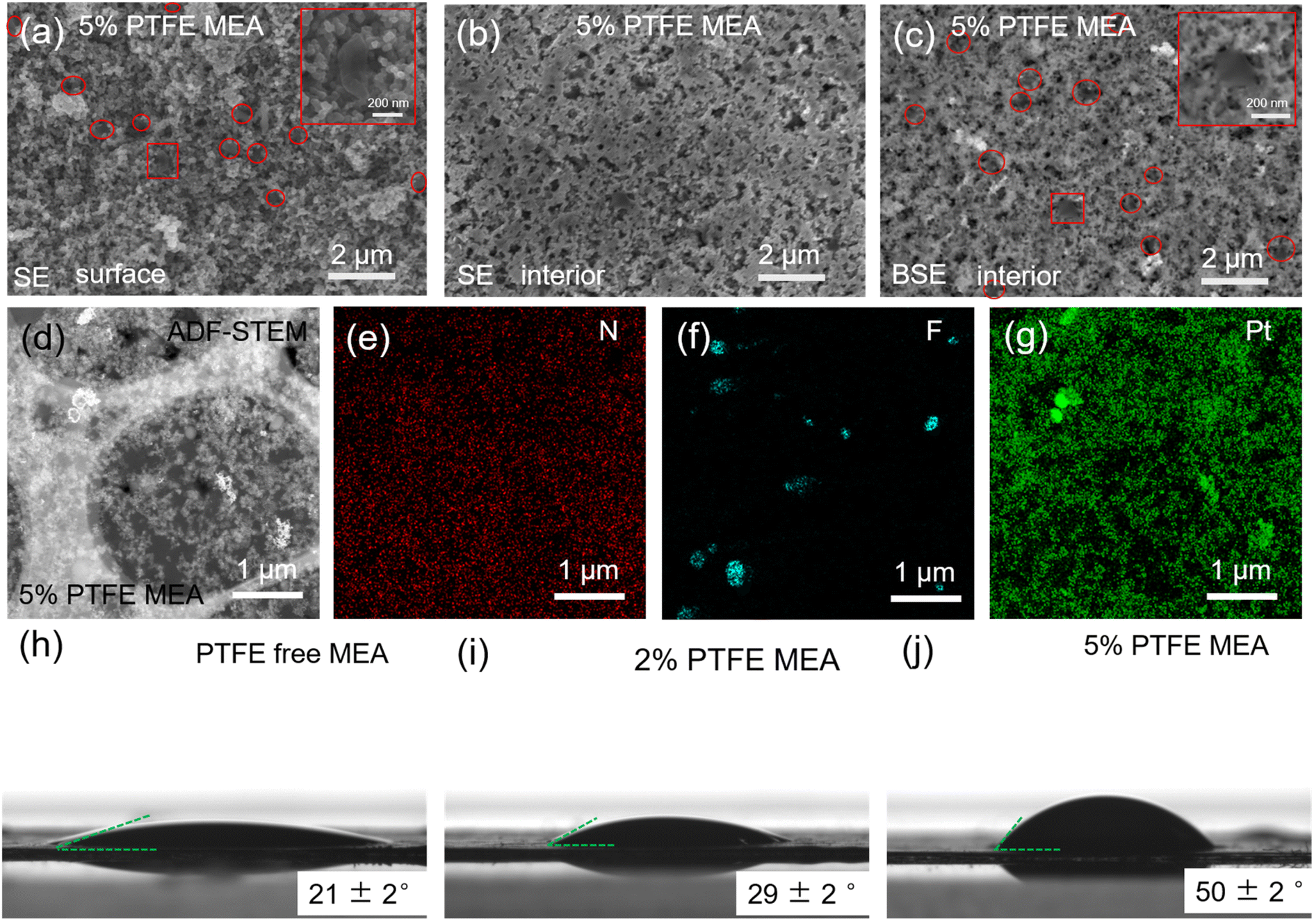 | ||
| Fig. 1 (a) Surface morphology of the catalyst layer and the distribution of PTFE in its surface (PTFE particles are highlighted with red circles); the internal microstructure of the 5% PTFE MEA catalyst layer captured in SE (secondary electron) (b) and BSE (backscattered electron) (c) modes. The regions marked in red boxes in (a) and (c) are PTFE particles. (d) ADF-STEM image of 5% PTFE MEA catalyst layer; (e–g) distribution of elements N, F, and Pt. (h–j) The contact angle test results of conventional MEA, 2% and 5% PTFE MEA, respectively. The error bars indicate the standard deviation from three independent measurements. | ||
In order to study the effect of the added PTFE on the hydrophobicity of the catalyst layer, we performed contact angle measurements on MEAs of different PTFE contents (Fig. 1h–j). The contact angle increases with the amount of PTFE in the catalyst layer, from 21 ± 2° with PTFE-free MEA to 50 ± 2° with 5% PTFE MEA, which confirms an improved hydrophobicity of the catalyst layers with the addition of PTFE.
Electrochemical current step has been shown as an effective method to elucidate water dynamics in the catalyst layer of MEA.30 A sudden change in the current density induces thermal fluctuations that influence water evaporation in the catalyst layer, which further induces voltage fluctuations. Therefore, analyzing the voltage behavior of fuel cells during the current step test provides insights into water dynamics in the catalyst layer. As shown in Fig. 2a and c, the correlation between the hydrophobicity of the catalyst layer and the voltage step behavior is evident. In PTFE-free MEA, within the current density range of 1.5–2.8 A cm−2, lowering the current density leads to a clear decaying behavior of the cell voltage (highlighted in red boxes in Fig. 2a): when the current steps down by 0.25 A cm−2, the voltage ramps up initially and then gradually decreases until it stabilizes. From this phenomenon, we can interpret the water dynamics as follows: at high current densities (>2.8 A cm−2), the large amount of heat generated in the fuel cell suffice to evaporate the excess water (the product of the fuel cell reaction) in the catalyst layer (which would otherwise affect the mass transport), resulting in a stable voltage change. As the current density steps down, the produced heat reduces, and the excess water accumulates in the catalyst layer, hindering mass transfer and thus leading to a gradual decline in the voltage after current stepping. At even lower current densities (<1.5 A cm−2), the voltage becomes unaffected by mass transport again, because of the reduced amount of water generated during fuel cell operation. In contrast, when the hydrophobicity of the catalyst layer increases after the addition of PTFE, it is easier for the water generated internally to be exhausted out of the MEA, alleviating the mass transfer issues due to excessive water retention. As a result, 5% and 2% PTFE MEA exhibit a more stable voltage profile when the current density varies (see Fig. 2c and e).
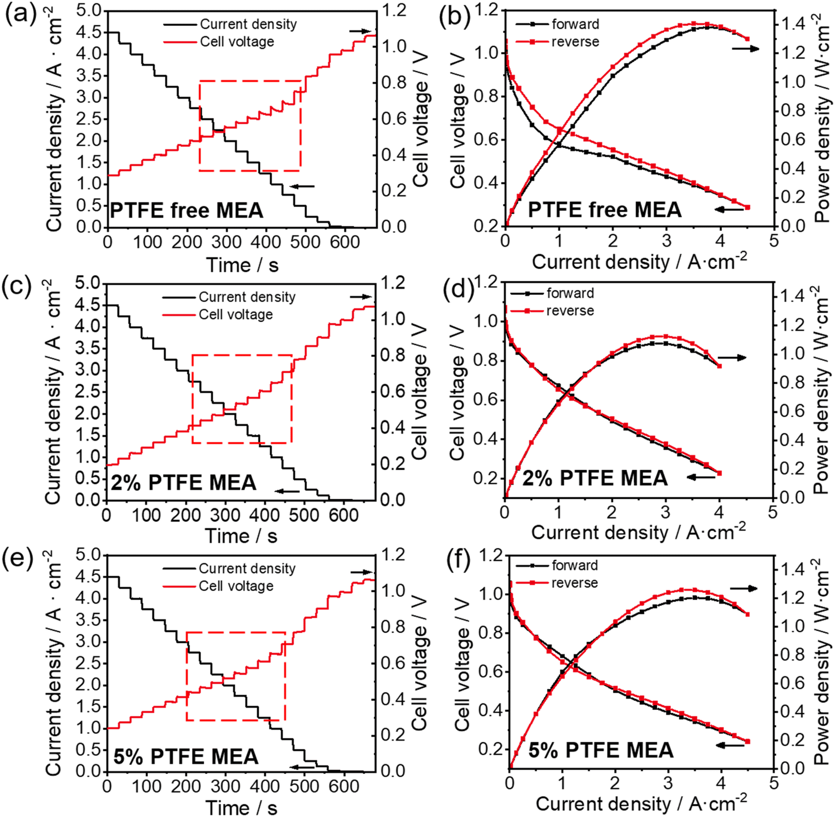 | ||
| Fig. 2 Current step (a, c and e) and polarization curves (b, d and f) test of conventional (a and b), 5% PTFE MEA (c and d) and 5% PTFE MEA (e and f). | ||
Similarly, we can obtain information about the water content variation of the catalyst layer during the cell operation from electrochemical polarization curves. Fig. 2b, d and f show the polarization curves for the conventional, 2% and 5% PTFE MEA, respectively. In the absence of PTFE, the pristine MEA shows significant hysteresis in the forward and reverse scanning curves, which overlap poorly as shown in Fig. 2b. With the addition of PTFE, the overlap between forward and reverse scans in the polarization curve significantly improves. The poor overlap in the forward and reverse polarization curves is often linked to the uneven water distribution during fuel cell testing.34 In forward scanning, less heat is generated in the catalyst layer at low current densities, but as the current density increases, the water generated inside begins to hinder the mass transfer of gas (i.e., flooding). Conversely, in reverse scanning, the heat accumulated at high current densities promotes water evaporation in the catalyst layer, thereby reducing the mass transfer resistance caused by flooding. As a result, in the conventional MEA, the voltage in forward scanning is lower than that in reverse scanning at the same current densities, causing the hysteresis in the polarization curve (Fig. 2b). In the case of 2% and 5% PTFE MEAs, the increased hydrophobicity significantly reduces the influence of fluctuating water content on voltage at different current densities. Therefore, better overlapping is observed in the polarization curves of the PTFE-modified MEA (Fig. 2d and f).
The above results from the electrochemical current step and polarization measurements are consistent with previous analysis of the effect of water on electrochemical behaviors.30 The results indicate that increasing the hydrophobicity of the catalyst layer by PTFE incorporation has a positive impact on the water management of APEFC during operation, which can reduce the fluctuation of water content in the catalyst layer. However, it is also evident from the electrochemical polarization curves that the addition of PTFE tends to lower the peak power density (Fig. 2). As PTFE particles are neither ionically nor electrically conductive, their presence in the catalyst layer will affect the charge transport within MEA, despite the apparent benefit in mass transport discussed above. Therefore, it is critical to evaluate the amount of PTFE for a balanced charge transport and mass transport.
3.2 Evaluating the structural stability and the electrochemical durability of PTFE-modified MEA
We next evaluate the electrochemical durability of fuel cells with different amounts of PTFE, and all the tested cells were operated until they naturally ceased running due to excessive degradation. The incorporation of PTFE has substantially improved the durability of the MEA, as compared in Fig. 3. Specifically, the APEFC with 2% PTFE MEA shows a durability of 130 h, with its voltage decrease from 0.63 V to 0.4 V at a rate of 2.9 mV h−1 in the first 80 h. In contrast, the cell with 5% PTFE MEA lasts for 120 h, with a slower decay rate of 2.4 mV h−1. This indicates that the durability after adding PTFE is greater than the 83 h durability of conventional MEA (voltage decay rate of 3.1 mV h−1). Compared with previous publications (Table S1†), the durability of our PTFE MEA exhibits a lower voltage decay rate.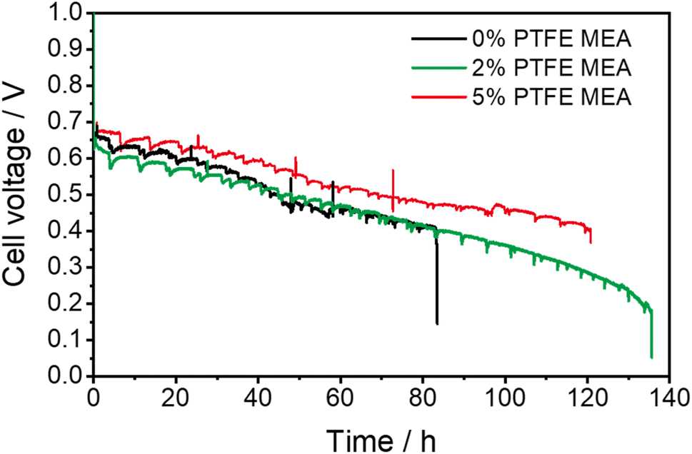 | ||
| Fig. 3 Durability comparison of PTFE MEAs and conventional MEA. The durability test is set at a current density of 1 A cm−2, with a back pressure of 200 kPa and a temperature of 80 °C, and the flow rate was 1000 mL min−1. The voltage–time curves of repeated tests are shown in Fig. S5.† | ||
Following the durability test of MEAs, we employed FE-SEM to characterize the changes of the pore structure inside the catalyst layer. The addition of PTFE to the catalyst layer reduced its structural degradation during fuel cell operation, as fewer cracks in the catalyst layers are observed in PTFE-modified MEAs compared to the pristine MEA (Fig. 4a–h). We further performed quantitative analysis on the pore structure evolution before and after the durability test for different MEAs (Fig. 4i and j), which is achieved by image segmentation based on machine learning and local thickness methods. For the PTFE-free MEA, the porosity of the anode and cathode sections of the catalyst layer is reduced by 14% and 9%, respectively. When PTFE is added, the reduction of porosity after the durability test is alleviated. With 2% PTFE, the porosity reduction of the MEA is only 7% for anode and 4% for cathode. With 5% PTFE, the porosity values of both electrodes are almost maintained at 49%. Concurrently, for the PTFE-free MEA, the solid components in both the cathode and anode show significant agglomeration after the durability test, with 74% and 54% increase in average agglomeration size for the anode and the cathode, respectively. When 2% PTFE is added, the corresponding values are reduced to 23% for anode and 26% for cathode. When PTFE loading is further increased to 5%, the enlargement of the average agglomeration size of the solid components is only 8% for anode and 10% for cathode. The reduced changes in porosity and the size of the agglomeration size of the solid components upon PTFE modification alleviate the negative impact of the catalyst layer degradation on the catalyst's utilization and the transfer of gas and water within the catalyst layer.
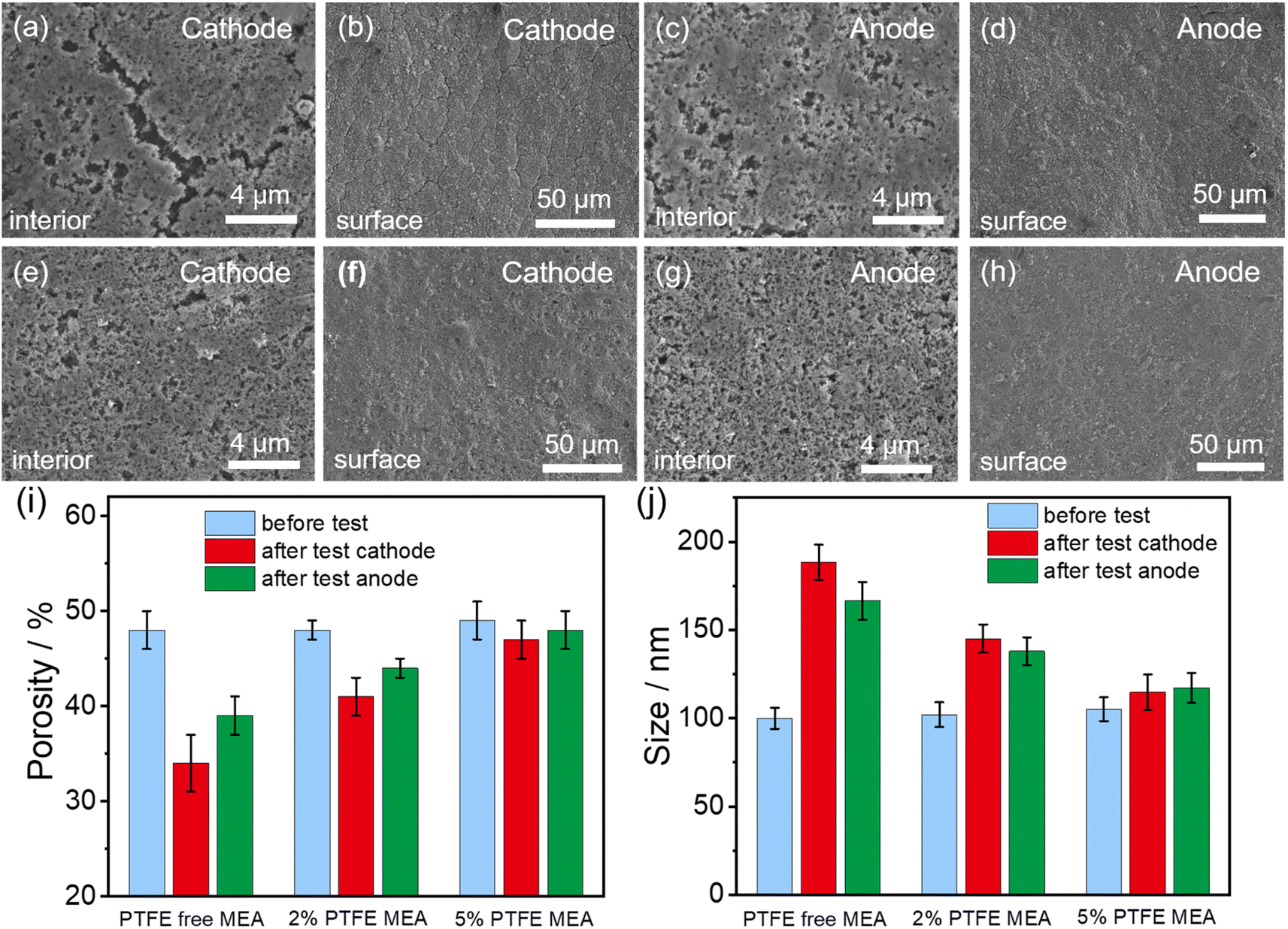 | ||
| Fig. 4 Structural changes in the internal (a, c, e and g) and surface (b, d, f and h) of the catalyst layers in conventional MEA (a–d) and 5% PTFE MEA (e–h) following the durability test. Changes in the porosity (i) and the average agglomeration size of the solid components (j) of the catalyst layer before and after the durability test. The original FE-SEM images and segmented images of the conventional MEA and PTFE MEA before durability test are shown in Fig. S3.† Detailed quantitative analysis of the pore structure in MEA catalyst layers with different PTFE contents is presented in Fig. S6.† | ||
The FE-SEM results demonstrate that the incorporating of PTFE significantly enhances the structural stability of the catalyst layer. This enhancement is primarily attributed to PTFE's hydrophobic properties, which helps to reduce the water content fluctuations within the catalyst layer. Through this mechanism, the volume change of the ionomer is alleviated,22 thus greatly reducing the mechanical stress encountered during the cell operation. Consequently, the stability of the catalyst layer structure is preserved. Even with the addition of PTFE, the cathode catalyst layer's pore structure deteriorates more severely than that of the anode (Fig. 4e and g). The inconsistency in pore structure degradation between the two electrodes may be attributed to water distribution during cell operation. Specifically, the anode is prone to water flooding, which keeps the ionomer hydrated during cell operation. This condition reduces the shrinkage and expansion of ionomers due to wet-dry variations, thereby mitigating structural degradation. In contrast, the cathode environment is drier and undergoes more intense wet-dry variations, which can severely damage the pore structure and accelerate degradation. In addition, the degradation of ionomers may also be another important reason. Ionomer degradation may reduce bonding and adhesion performance, further compromising the structural integrity of the catalyst layer. Particularly on the cathode side, where drying, ionomer degradation may be more severe.12
We further analyzed the interface between the catalyst layer and the membrane of the MEAs after the durability test using FE-SEM, as shown in Fig. 5. The FE-SEM images at low magnification show that the catalyst layer of 5% PTFE MEA exhibits partial separation from the membrane at the cathode side after the durability test (Fig. 5f), which is not observed on MEA with 2% PTFE and the PTFE-free MEA (Fig. 5e). This illustrates that although 5% PTFE MEA is better than 2% PTFE MEA at suppressing the changes of porosity and agglomeration size of the solid components (Fig. 4), the durability of the former is poor (Fig. 3). We conclude that excess amount of PTFE in the catalyst layer affects its adhesion to the membrane and hence the durability of the fuel cell, and this suggests that the PTFE content needs to be reasonably controlled for longer durability.
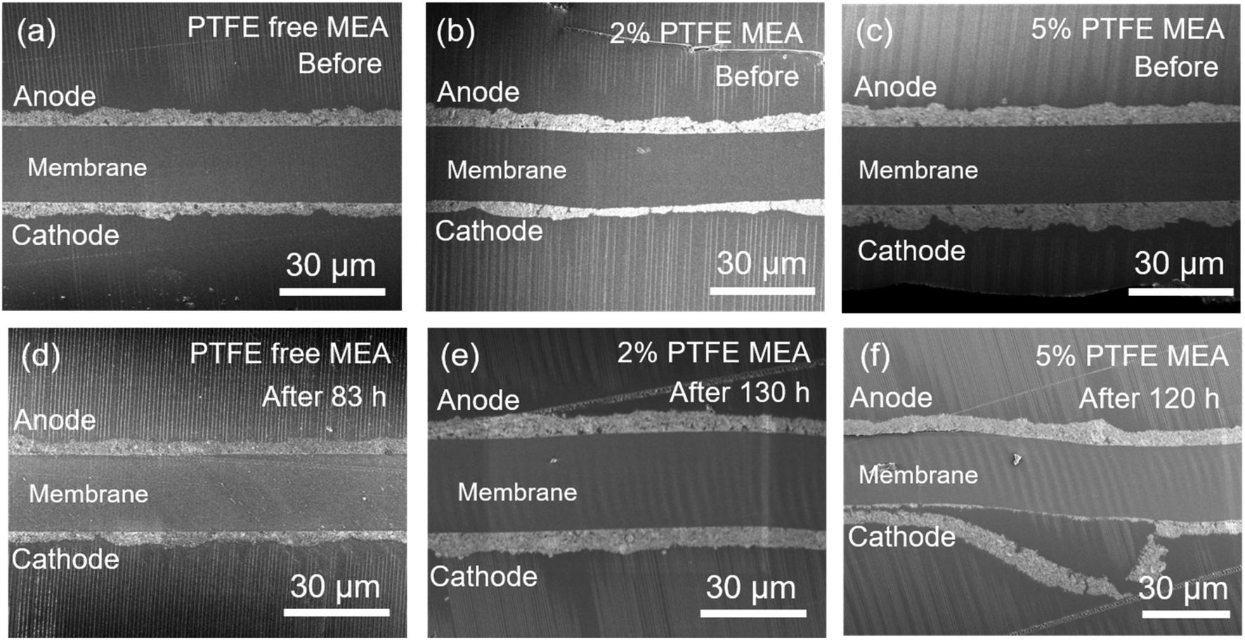 | ||
| Fig. 5 FE-SEM images of the cross-section of the catalyst layer before (a–c) and after (d–f) durability test. (a and d) Conventional MEA, (b and e) 2% PTFE MEA, (c and f) 5% PTFE MEA. | ||
We employed TEM to analyze both 5% and conventional MEA after the durability test, with results displayed in Fig. S7–S9.† Fig. S7† demonstrates that, before the durability test, Pt particles were generally uniformly dispersed, but there is also partial agglomeration can be seen. The particle size of Pt is concentrated in 2–5 nm, which is more than 99%. In the conventional MEA (Fig. S8†), Pt particles aggregation was observed at both cathode and anode after the durability test (Fig. S8b and e†). However, there was minimal growth in overall particle size, with particles larger than 5 nm constituting only 4.2% at the cathode and 4% at the anode (Fig. S8c and f†). In the 5% PTFE MEA (Fig. S9†), more severe aggregation of Pt particles was noted, particularly at the cathode (Fig. S9b and e),† with significant increases in particle size. Particles larger than 5 nm comprised 24% at the cathode and 7.8% at the anode, respectively (Fig. S9c and f†). The greater particle size growth in 5% PTFE MEA compared to conventional MEA could be attributed to the longer durability test time. Although more severe Pt particle size growth was observed in 5% PTFE MEA, its durability still surpasses that of conventional MEA. This result further highlights the important role of stable pore structure in improving durability.
From TEM images in Fig. S7 and S8,† we can see some signs of particle bonding, which may be due to the migration of the Pt particles in proximity to each other and begin to fuse together. This suggests that the growth in Pt particle size is attributable to agglomeration. In addition, analyzing particle size distribution forms can determine the growth mechanism: a distribution with a tail towards smaller sizes typically indicates Ostwald ripening, while a tail towards larger sizes suggests agglomeration mechanism.35–37 As depicted in Fig. S8c and f,† the Pt particle size distribution tails towards larger particles, indicating that Pt particle size growth is primarily due to agglomeration.
4 Conclusion
Designing hydrophobic MEA by integrating PTFE into the catalyst layer proves to be a promising strategy for improving the stability and durability of APEFCs. The stable voltage platform in electrochemical current stepping tests and the improved overlap in the forward and reverse scans in electrochemical polarization curves demonstrate that the PTFE can promote the removal of excess water, thereby reducing the fluctuation of water content in the catalytic layer. Compared to the conventional MEA, the PTFE-modified MEAs show 57% and 45% enhancement in durability with 2% PTFE MEA and 5% PTFE MEA, respectively. Additionally, structural characterization of the MEA after the durability test revealed that the pore structure of the PTFE MEA experienced less change compared to the conventional MEA. The superior durability and structural stability show the effectiveness of PTFE MEA in improving durability and a more stable catalyst layer structure. Our findings highlight the potential of PTFE modification to address the mechanical degradation of the catalyst layer structures in APEFCs, offering a promising pathway to improve the durability of fuel cells.Data availability
The data that support the findings of this study are available upon request from the authors.Author contributions
J. M. and L. W. C. conceived the research. J. M. carried out the experiments with help from other authors. J. M., L. W. C. and P. X. wrote the manuscript with input from all other authors.Conflicts of interest
The authors declare no competing interest.Acknowledgements
This work was supported by the National Natural Science Foundation of China (No. 21991153, 21991150). We extend our sincere gratitude to Hitachi High-Tech Scientific Solutions (Beijing) Co., Ltd and Oxford Instrument Technology (Shanghai) Co., Ltd for their generous support in electron microscopy. In particular, we would like to thank Dr Sibing Wang for his invaluable assistance with the Hitachi Regulus 8240 FE-SEM. P. X. acknowledges the support of the Xiaomi Young Talents Program from Xiaomi Foundation.References
- Y. Gao, Y. Yangb, R. Schimmentic, E. Murrayc, H. Penga, Y. Wanga, C. Gea, W. Jianga, G. Wanga, F. J. DiSalvob, D. A. Mullere, M. Mavrikakisc, L. Xiao, H. D. Abruña and L. Zhuang, Proc. Natl. Acad. Sci. U.S.A., 2022, 119, e2119883119 CrossRef CAS PubMed.
- H. Adabi, A. Shakouri, N. Ul Hassan, J. R. Varcoe, B. Zulevi, A. Serov, J. R. Regalbuto and W. E. Mustain, Nat. Energy, 2021, 6, 834–843 CrossRef CAS.
- S. Lu, J. Pan, A. Huang, L. Zhuang and J. Lu, Proc. Natl. Acad. Sci. U.S.A., 2008, 105, 20611–20614 CrossRef CAS.
- J. Hyun and H.-T. Kim, Energy Environ. Sci., 2023, 16, 5633–5662 RSC.
- W. Yuan, L. Zeng, S. Jiang, C. Yuan, Q. He, J. Wang, Q. Liao and Z. Wei, J. Membr. Sci., 2022, 657, 120676 CrossRef CAS.
- Q. Li, H. Peng, Y. Wang, L. Xiao, J. Lu and L. Zhuang, Angew. Chem., Int. Ed., 2019, 58, 1442–1446 CrossRef CAS PubMed.
- N. Chen, C. Hu, H. H. Wang, S. P. Kim, H. M. Kim, W. H. Lee, J. Y. Bae, J. H. Park and Y. M. Lee, Angew. Chem., Int. Ed., 2021, 60, 7710–7718 CrossRef CAS PubMed.
- J. Liu, L. Gao, W. Chen, X. Jiang, X. Yan and G. He, J. Membr. Sci., 2024, 692, 122260 CrossRef CAS.
- D. R. Dekel, J. Power Sources, 2018, 375, 158–169 CrossRef CAS.
- G. Huang, M. Mandal, X. Peng, A. C. Yang-Neyerlin, B. S. Pivovar, W. E. Mustain and P. A. Kohl, J. Electrochem. Soc., 2019, 166, F637–F644 CrossRef CAS.
- L. Wang, X. Peng, W. E. Mustain and J. R. Varcoe, Energy Environ. Sci., 2019, 12, 1575–1579 RSC.
- W. E. Mustain, M. Chatenet, M. Page and Y. S. Kim, Energy Environ. Sci., 2020, 13, 2805–2838 RSC.
- Hydrogen and Fuel Cell Technologies Office, DOE, Research and Development Goals, https://www.energy.gov/eere/fuelcells/fuel-cells Search PubMed.
- A. Raut, H. Fang, Y. C. Lin, S. Fu, D. Sprouster, R. Shimogawa, A. I. Frenkel, C. Bae, J. C. Douglin, J. Lillojad, K. Tammeveski, Z. Zeng, S. Bliznakov, M. Rafailovich and D. R. Dekel, Angew. Chem., Int. Ed., 2023, 62, e202306754 CrossRef CAS PubMed.
- N. Ul Hassan, M. J. Zachman, M. Mandal, H. Adabi Firouzjaie, P. A. Kohl, D. A. Cullen and W. E. Mustain, ACS Catal., 2022, 12, 8116–8126 CrossRef CAS.
- Q. Li, M. Hu, C. Ge, Y. Yang, L. Xiao, L. Zhuang and H. D. Abruña, Chem. Sci., 2023, 14, 10429–10434 RSC.
- J. Ma, D. Meng, Y. Zhang, H. Ma, Z. Ren, J. Zhang, L. Xiao, L. Zhuang, L. Li and L. Chen, J. Power Sources, 2023, 587, 233687 CrossRef CAS.
- C. G. Arges and V. Ramani, Proc. Natl. Acad. Sci. U.S.A., 2013, 110, 2490–2495 CrossRef CAS PubMed.
- C. Fujimoto, D.-S. Kim, M. Hibbs, D. Wrobleski and Y. S. Kim, J. Membr. Sci., 2012, 423–424, 438–449 CrossRef CAS.
- K. Yassin, I. G. Rasin, S. Willdorf-Cohen, C. E. Diesendruck, S. Brandon and D. R. Dekel, J. Power Sources Adv., 2021, 11, 100066 CrossRef CAS.
- J. Zhang, W. Zhu, T. Huang, C. Zheng, Y. Pei, G. Shen, Z. Nie, D. Xiao, Y. Yin and M. D. Guiver, Adv. Sci., 2021, 8, 2100284 CrossRef CAS PubMed.
- X. Peng, D. Kulkarni, Y. Huang, T. J. Omasta, B. Ng, Y. Zheng, L. Wang, J. M. LaManna, D. S. Hussey, J. R. Varcoe, I. V. Zenyuk and W. E. Mustain, Nat. Commun., 2020, 11, 1–11 CrossRef PubMed.
- Y. Tang, M. H. Santare, A. M. Karlsson, S. Cleghorn and W. B. Johnson, J. Fuel Cell Sci. Technol., 2006, 3, 119–124 CrossRef CAS.
- B. Xiao, J. Zhao, Z. Tu and S. H. Chan, Int. J. Hydrogen Energy, 2021, 46, 38040–38050 CrossRef CAS.
- J. Park, X. Li, D. Tran, T. Abdelbaset, D. Hussey, D. Jacobson and M. Arif, Int. J. Hydrogen Energy, 2008, 33, 3373–3384 CrossRef CAS.
- Y. Yin, R. Li, F. Bai, W. Zhu, Y. Qin, Y. Chang, J. Zhang and M. D. Guiver, Electrochem. Commun., 2019, 109, 106590 CrossRef CAS.
- Y. Chang, J. Liu, R. Li, J. Zhao, Y. Qin, J. Zhang, Y. Yin and X. Li, Energy Convers. Manage., 2019, 189, 24–32 CrossRef CAS.
- R. Lin, H. Wang and Y. Zhu, Energy, 2021, 221, 119909 CrossRef CAS.
- N. Ul Hassan, M. Mandal, G. Huang, H. A. Firouzjaie, P. A. Kohl and W. E. Mustain, Adv. Energy Mater., 2020, 10, 2001986 CrossRef CAS.
- M. Hu, Q. Li, H. Peng, H. Ma, L. Xiao, G. Wang, J. Lu and L. Zhuang, J. Power Sources, 2020, 472, 228471 CrossRef CAS.
- I. Arganda-Carreras, V. Kaynig, C. Rueden, K. W. Eliceiri, J. Schindelin, A. Cardona, H. Sebastian Seung and R. Murphy, Bioinformatics, 2017, 33, 2424–2426 CrossRef CAS PubMed.
- H. Peng, Q. Li, M. Hu, L. Xiao, J. Lu and L. Zhuang, J. Power Sources, 2018, 390, 165–167 CrossRef CAS.
- S. Chen, H. Peng, M. Hu, G. Wang, L. Xiao, J. Lu and L. Zhuang, ACS Appl. Energy Mater., 2021, 4, 4297–4301 CrossRef CAS.
- K. Otsuji, Y. Shirase, T. Asakawa, N. Yokota, K. Nagase, W. Xu, P. Song, S. Wang, D. A. Tryk, K. Kakinuma, J. Inukai, K. Miyatake and M. Uchida, J. Power Sources, 2022, 522, 230997 CrossRef CAS.
- Y. Shao-Horn, P. Ferreira, G. J. la O’, M. Dane, H. A. Gasteiger and M. Rohit, ECS Trans., 2006, 8, 185–195 CrossRef.
- M. C. Josef, G. Carolina, K. Ioannis, T. A. Angel, K. Aleksander, S. Ferdi and M. J. J. Karl, ACS Catal., 2012, 2, 832–843 CrossRef.
- V. Benoit, C. Marian, G. Laure and M. Frédéric, ECS Trans., 2011, 41, 697–708 CrossRef.
Footnote |
| † Electronic supplementary information (ESI) available. See DOI: https://doi.org/10.1039/d4ra04019h |
| This journal is © The Royal Society of Chemistry 2024 |