 Open Access Article
Performance optimization of metal-supported solid oxide fuel cells using cathode and full cell impregnation with La0.4Sr0.6Co0.2Fe0.7Nb0.1O3−δ electrode†
Xin Songab,
Che Wangab,
Na Xu *ab,
Zhanlin Xu*b and
Junling Meng
 *ab
*ab
aKey Laboratory of Preparation and Application of Environmental Friendly Materials of Ministry of Education, Jilin Normal University, Changchun, 130103, China. E-mail: xuna8912@126.com; mengjunling@jlnu.edu.cn
bDepartment of Chemistry, Jilin Normal University, Siping, 136000, China. E-mail: xuzhanlin1964@163.com
First published on 24th September 2024
Abstract
In this study, precursor solutions of La0.4Sr0.6Co0.2Fe0.7Nb0.1O3−δ (LSCFN) symmetric electrode were prepared, and the applications of cathode impregnation and full cell impregnation in the preparation and performance optimization of four-layer metal-supported solid oxide fuel cells (MSCs) were thoroughly investigated. Test results indicate that the polarization impedance of cathode impregnated MSCs under H2 and CH4 atmospheres at 750 °C is approximately 0.1 Ω cm2 and 0.41 Ω cm2, respectively, with power densities of 1115 mW cm−2 and 700 mW cm−2, respectively. Meanwhile, the polarization impedance of full cell impregnated MSCs under the same conditions is 0.12 Ω cm2 and 0.40 Ω cm2, with power densities of 945 mW cm−2 and 840 mW cm−2, respectively. Remarkably, MSCs full cell impregnated LSCFN exhibit outstanding stability performance under CH4 atmosphere in a 100 h stability test. Research on the application of impregnation method for performance optimization of metal-supported cells is relatively scarce. The results reveal the feasibility of simplifying MSCs preparation steps using full cell impregnation method, further promoting the widespread application of metal-supported overall cells.
1. Introduction
Solid oxide fuel cells (SOFCs) have gained widespread recognition due to their remarkable energy conversion efficiency, versatile applicability, fuel flexibility, and minimal emissions.1,2 The evolution of SOFCs can be categorized into three generations based on the type of support structure.3 The first generation includes electrolyte-supported SOFCs, followed by the second generation comprising electrode-supported SOFCs. The third generation introduces metal-supported SOFCs (MSCs), which utilize metal support structures instead of traditional ceramic supports for oxygen electrodes, hydrogen electrodes, and electrolytes.4,5 MSCs exhibit improved mechanical strength, enhanced thermal and electrical conductivity, better thermal shock resistance, and reduced cost. Moreover, they offer notable advantages such as operation at moderate to low temperatures, rapid start-up, and thermal cycle stability.6,7Despite these advantages, research on MSCs remains relatively scarce worldwide. When applied to MSCs, both cathode and anode components encounter certain limitations that hinder the scalable production and commercial utilization of MSCs. For instance, compared to nickel-based anode catalytic activity, traditional perovskite cathodes exhibit lower reactivity. The method of cathode preparation involving high-temperature air sintering poses challenges, leading to the re-oxidation of the metal support structure and potential issues like electrolyte cracking or reduced nickel electron conductivity.8,9 Additionally, the introduction of carbon-based fuels into MSCs readily results in carbon deposition on nickel-based anodes.10
Hence, enhancing the structure of MSCs and developing high-performance and highly stable electrodes are essential pathways to improve the performance of MSCs and drive their applications. Employing the same material in adjacent structures within the metal support layer, anode, electrolyte and cathode of MSCs can mitigate the coefficient of thermal expansion. For instance, constructing a semi-cell framework with the configuration Ni–Fe|Ni–YSZ|YSZ|Porous-YSZ (Y2O3 stabilized ZrO2) using a co-extrusion method allows for simultaneous sintering of the entire MSCs framework.11 Solution impregnation methods facilitate the attainment of nanoscale, highly active electrodes at lower sintering temperatures.12–14 This approach circumvents issues arising from excessive support structure oxidation due to high-temperature air sintering. Additionally, nanoelectrodes produced through the impregnation method feature a substantial “electronic conduction phase-ion conduction phase-gas” triple phase boundary, significantly enhancing the catalytic performance of the cell, while also effectively mitigating the issue of thermal expansion mismatch between the electrode and the electrolyte.15,16
For traditional ceramic-supported SOFCs, achieving impregnation requires sacrificing strength to prepare a more porous anode. This constraint has hindered the development of anode impregnation in SOFCs. In contrast, MSCs, utilizing strong porous alloys as the support structure, hold a distinct advantage for anode impregnation.17,18
Impregnating cathodes and anodes separately are a laborious and time-consuming process. In recent years, the emergence of various perovskite symmetrical electrode materials stable under oxidative and reductive atmospheres, such as Sr2Fe1.5Mo0.5O6−δ, Sm0.7Sr0.2Fe0.8Ti0.15Ru0.05O3−δ and Pr0.4Sr0.6Co0.2Fe0.7Nb0.1O3−δ,19–21 undeniably offers the potential for constructing overall MSCs using a unified impregnation approach. Researchers have predominantly employed redox-stable perovskite materials as symmetrical electrode materials in SOFCs. In contrast to redox-stable electrode materials, redox-reversible electrode materials may undergo structural changes in reducing atmospheres, leading to the uniform dispersion of active nanometallic particles on certain electrode surfaces, while the bulk structure remains largely unaffected. The applicant's team has designed and developed redox-reversible La0.4Sr0.6Co0.2Fe0.7Nb0.1O3−δ (LSCFN) perovskite and similar materials, where reduction conditions induce the precipitation of Co–Fe nanometallic particles at the B sites.22 This transforms LSCFN into a stable layered perovskite structure, which reverts to its perovskite morphology under oxidative atmospheres. Electrode performance remained unimpaired over 21 cycles, rendering LSCFN more suitable for MSCs application than redox-stable perovskites.23
Currently, few research groups have explored MSCs development or employed full cell impregnation methods to lower operational temperatures and streamline fabrication procedures. This study assesses the constructed and prepared MSCs through comprehensive testing while also endeavoring to optimize impregnation using full cell impregnation methods to enhance cell performance and stability.
2. Material and methods
The preparation method for the Ni–Fe|Ni–YSZ|YSZ|Porous-YSZ half-cell framework was adopted from a previously published paper by the research group.11 Four layers of green bodies were obtained through tape casting, followed by pellet stamping to achieve a diameter of 19 mm. Then, the half-cell of NiO–Fe2O3/NiO–YSZ/YSZ/P-YSZ was obtained after sintering in a muffle furnace at 1300 °C for 5 h in an air atmosphere. Furthermore, half-cells with a structure of NiO–YSZ/YSZ/P-YSZ were fabricated using the same method. Subsequently, they were impregnated during full cell impregnation and used for characterizing the anode via X-ray diffraction instrument (XRD).For the chemical composition of La0.6Sr0.4Co0.2Fe0.7Nb0.1O3−δ (LSCFN), specific amounts of La(NO3)3·6H2O, Sr(NO3)2, Co(NO3)2·6H2O, Fe(NO3)3·9H2O, and C10H5NbO20·6H2O were weighed and combined with deionized water in a beaker. This mixture was heated and stirred until complete dissolution. Quantities of citric acid were introduced to the impregnation solution to facilitate perovskite phase formation. The concentration of the LSCFN impregnation solution was set at 0.5 mol L−1, and excess water was evaporated to obtain the required impregnation solution.
Through vacuum impregnation, the previously high-temperature sintered NiO–Fe2O3/NiO–YSZ/YSZ/P-YSZ and NiO–YSZ/YSZ/P-YSZ half-cell frameworks underwent separate cathode impregnation and full cell impregnation. Impregnation was carried out in a vacuum for 2 h, after which the surface impregnation liquid was wiped clean. The impregnated frameworks were then in situ sintered at 800 °C for 2 h in a muffle furnace. This process was repeated three times to achieve a single cell (S1–S2).
For the preparation of LSCFN perovskite electrode powder, the impregnation solution was directly calcined. The sintering temperature and duration matched those post-impregnation in the cell, set at 800 °C for 2 h. Simulating impregnation into the anode involved introducing the powder into a reducing atmosphere.
The LSCFN powder's phase was analyzed using a multifunctional XRD (Germany's Bruker D8). Surface chemical states and atomic composition were investigated using X-ray photoelectron spectroscopy (XPS, U.S. Escalab 250Xi). Microscopic electrode morphology was observed using a scanning electron microscope (SEM, Germany's Merlin Compact). Gold paste was utilized as the electrode collector for both cathode and anode. Electrochemical performance was evaluated using the PGSTAT302N electrochemical workstation (Metrohm Autolab, Switzerland). Electrochemical impedance spectroscopy was conducted with a perturbation amplitude of 20 mV and a frequency range of 0.1 Hz to 106 Hz. Similarly, the electrochemical workstation was employed to test the current density (I)–voltage (V)–power density (P) performance of the cells under different fuel gases. The cathode was exposed to atmospheric conditions, while the anode was subjected to a flow of H2 and CH4 at a flow rate of 50 mL min−1.
3. Result and discussion
3.1 Electrode material electrochemical performance testing
The structural characterization of the LSCFN powder sintered in air at 800 °C is shown in Fig. 1(a). No diffraction peaks corresponding to impurity phases were detected, indicating the sample's pure perovskite phase. Considering that the common oxidation state of Nb ions in perovskite oxides is +5, and the ionic radius of Nb5+ (0.064 nm) is larger than that of Fe (with Fe4+ and Fe3+ having ionic radii of 0.0585 nm and 0.055 nm, respectively), partial substitution of Fe by Nb in LSCF leads to an increased unit cell volume and a slight shift in peak position to lower 2θ angles.24 As the cell was integrally impregnated and the LSCFN located at the anode was exposed to a reducing atmosphere for an extended period, the LSCFN powder obtained after 800 °C sintering was subjected to a reduction treatment in a horizontal atmosphere furnace with H2/N2–3% H2O atmosphere for 50 h. Subsequent XRD measurements revealed that after prolonged reduction, significant Co–Fe alloy impurities appeared on the LSCFN perovskite phase, yet the overall structure retained the ABO3 configuration. The XRD pattern showed a peak shift towards lower angles, attributed to the decrease in oxidation states of ions under reduction conditions. Following the charge compensation mechanism, this results in lattice oxygen loss and subsequent peak position shift towards lower angles.25 Thus, the anode-impregnated LSCFN mixed conductor can simultaneously possess catalytic decomposition of fuel gases and O2− transport functions during the early stages of cell testing.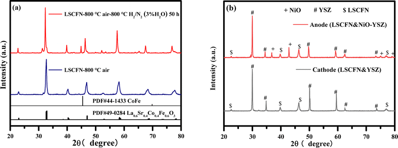 | ||
| Fig. 1 XRD analysis of LSCFN impregnation solution sintered at 800 °C then annealed at 800 °C for 50 h (a) and the surfaces of the cathode and anode of full cell impregnated MSCs (b). | ||
In this study, the half-cell framework was immersed in the LSCFN precursor solution using vacuum impregnation. LSCFN powder was mixed with the cathode framework material YSZ and the anode framework material NiO–YSZ, followed by co-sintering at 1000 °C for 5 h. The XRD results in Fig. 1(b) illustrate that there were no impurity phases in the cathode-side powder mixture after co-sintering, indicating the absence of reactions between LSCFN and YSZ at the operating temperature of the cell, preventing the formation of impurity phases. Similarly, on the anode side of the cell, only pure LSCFN perovskite phase, YSZ cubic fluorite phase, and NiO phase were observed, without any appearance of impurity phases.
To better elucidate the impact of LSCFN on ORR activity, XPS was employed to analyze the chemical environment of surface elements in LSCFN and H2-reduced LSCFN. Fig. 2(a) presents the XPS spectra of surface elements in both LSCFN and H2-reduced LSCFN samples. All binding energies were calibrated using the C 1s peak at 284.6 eV, confirming the presence of C, La, Sr, Co, Fe, Nb, and O. Fig. 2(b) shows the XPS spectra of the O 1s orbital in the electrode. The peak at 529.1 eV corresponds to lattice oxygen (Olat), the peak at 531.3 eV corresponds to surface-adsorbed oxygen (Oads), and the highest binding energy peak at 533.4 eV is associated with water-related oxygen species. The Olat/Oads ratio typically reflects the oxygen adsorption capacity of the electrode surface. A lower Olat/Oads ratio indicates a higher oxygen vacancy concentration, which is favorable for enhancing cathode ORR activity. Table 1 presents the Olat and Oads areas and the corresponding Olat/Oads percentages for the electrodes. A smaller Olat/Oads ratio suggests an increased oxygen vacancy concentration in LSCFN, thus enhancing its ORR activity. Both samples exhibit a high oxygen adsorption ratio, with the loosely bound Oads easily released at high temperatures, leaving numerous active sites that significantly enhance ORR activity. Notably, the Olat/Oads ratio in H2-reduced LSCFN is lower than in LSCFN, making it a more catalytically active ORR catalyst.
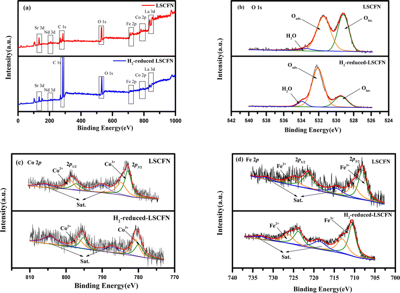 | ||
| Fig. 2 XPS survey spectra (a), O 1s XPS spectra (b), Co 2p XPS spectra (c), and Fe 2p XPS spectra (d) of LSCFN and H2-reduced LSCFN samples. | ||
| Sample | Olat (%) | Oads (%) | Olat/Oads |
|---|---|---|---|
| LSCFN | 43.68% | 56.31% | 0.77 |
| H2-reduced LSCFN | 22.57% | 77.42% | 0.29 |
Theoretically, the formation of oxygen vacancies within perovskites is accompanied by redox reactions of B-site cations. Therefore, to better understand the impact of reduction on the oxygen vacancy concentration, XPS analysis of B-site cations in LSCFN and H2-reduced LSCFN was conducted. Fig. 2(c) presents the Co 2p XPS spectrum of the LSCFN powder and H2-reduced LSCFN powder. The oxidation state of surface transition metal cations affects the surface electronic structure, the peaks near 794.7 eV and 796.2 eV correspond to Co 2p1/2, while those at 780.3 eV and 782.2 eV correspond to Co 2p3/2.26 The results indicate that upon H2 reduction, the Co 2p1/2 and Co 2p3/2 characteristic peak positions shift toward lower binding energies compared to the unreduced LSCFN. This is attributed to the reduction of Co3+ to Co2+ upon H2 reduction, leading to a decreased oxidation state of Co and resulting in the displacement of characteristic peaks to lower binding energies. Studies have shown that the transition between Co3+ and Co2+ oxidation states can enhance catalytic activity and electronic conductivity, improving the electrochemical performance of the cell.27
In Fig. 2(d), the Fe 2p XPS spectrum of the LSCFN powder and H2-reduced LSCFN powder are presented. The peaks at 723.8 eV and 726.2 eV correspond to Fe 2p1/2, while those at 710.5 eV and 713.0 eV correspond to Fe 2p3/2.28 The results show that post-H2 reduction, the Fe 2p1/2 and Fe 2p3/2 characteristic peak positions shift towards lower binding energies compared to unreduced LSCFN. This shift is attributed to the reduction of Fe3+ to Fe2+ upon H2 reduction, causing a decrease in Fe's oxidation state and leading to the displacement of characteristic peaks to lower binding energies. Studies have indicated that transitions between various oxidation states can enhance catalytic activity and electronic conductivity.29 Table 2 presents the percentages of Co and Fe ions in different valence states within the electrode and their corresponding average oxidation states. Comparing the average oxidation states of Co and Fe indicates that the B-site cations in H2-reduced LSCFN have a lower average oxidation state than in LSCFN, further confirming the higher oxygen vacancy concentration and enhanced ORR activity in H2-reduced LSCFN.
| Sample | Co 2p | Fe 2p | Average valence | |||
|---|---|---|---|---|---|---|
| Co2+ (%) | Co3+ (%) | Fe2+ (%) | Fe3+ (%) | Co | Fe | |
| LSCFN | 45.14% | 54.86% | 36.07% | 63.93% | 2.55 | 2.63 |
| H2-reduced LSCFN | 45.77% | 54.23% | 40.56% | 59.44% | 2.54 | 2.59 |
3.2 MSCs microstructure characterization
Fig. 3(a) presents an SEM image of the cross-section of the entire impregnated MSCs. As depicted in the figure, the cell exhibits a four-layer structure with close adhesion, free from any cracking or delamination. Moreover, the electrolyte presents a dense structure devoid of any observable cracks.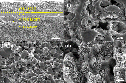 | ||
| Fig. 3 SEM images of the cross-sections of (a) full cell impregnated MSCs, (b) cathode, (c) anode, and (d) support. | ||
Fig. 3(b)–(d) depict the sectional microstructures of the YSZ–LSCFN cathode, Ni–YSZ–LSCFN anode, and Ni–Fe–LSCFN support in the full cell impregnated Ni–Fe–LSCFN/Ni–YSZ–LSCFN/YSZ/YSZ–LSCFN. The porous YSZ within the full cell impregnated cell is also saturated with ample LSCFN nanoparticles, evenly distributed, creating a substantial YSZ/LSCFN/gas three-phase interface.
In Fig. 3(c), we illustrate the microstructure of the Ni–YSZ–LSCFN anode, and its magnified SEM image reveals a uniform distribution of Ni particles within the anode, which are interspersed with larger YSZ particles. The surface of the Ni–YSZ anode is visibly impregnated with LSCFN nanoparticles. The presence of LSCFN on the YSZ electrolyte facilitates the catalysis and transfer of O2−, thereby expanding the anode's three-phase interface.
Fig. 3(d) portrays the microstructure of the support impregnated with LSCFN perovskite. The surface of the impregnated LSCFN layer exhibits no hindrance to the diffusion of fuel gas within the anode, while the mixed conductor LSCFN perovskite, covering the surface of the Ni–Fe alloy, prevents alloy oxidation and widens the ion transport pathway.
3.3 MSCs electrochemical performance testing
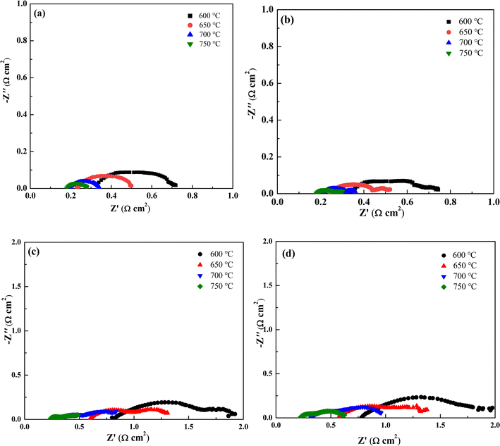
Electrochemical impedance spectroscopy can visually represent the electrochemical performance of a single cell. The spectra consist of arcs formed by a series of points, with intersections at the real axis (Z′) in both the high-frequency and low-frequency regions. The high-frequency intersection represents the ohmic resistance (Ro) of the single cell, primarily attributed to the electrolyte, electrode resistance, and interfacial contact resistance. The low-frequency intersection corresponds to the total resistance (Rt) of the cell. The difference between Rt and Ro defines the polarization resistance (Rp), which reflects the electrochemical catalytic performance of the electrode. Fig. 4(a) and (b) display the impedance spectra of cathode-impregnated and full cell impregnated LSCFN cells under H2 atmosphere. As the temperature increases, the impedance of the cells decreases, with both MSCs exhibiting the minimum impedance at 750 °C. The ohmic impedance of cathode-impregnated MSCs at 750 °C is approximately 0.18 Ω cm2, and the polarization impedance is approximately 0.1 Ω cm2. For full cell impregnated MSCs, the ohmic impedance at 750 °C is approximately 0.18 Ω cm2, and the polarization impedance is approximately 0.12 Ω cm2. After modifying the anode with full cell impregnation of LSCFN, the impedance slightly increases. This is likely due to the formation of a layer of LSCFN nanoparticles from the anode impregnation, partially adhering to the surface of Ni–YSZ, occupying some of the Ni–YSZ triple-phase boundary, hindering direct contact between H2 molecules and the surface of Ni particles and the triple-phase boundary. Previous studies by the research group have shown that the electron conductivity of LSCFN at 750 °C in H2 atmosphere is 35 S cm−1,30 it is significantly lower than that of Ni. Full cell impregnation may lead to increased impedance due to hindered ion-electron conduction at the triple-phase boundary.Fig. 4(c) and (d) show the impedance spectra of cathode-impregnated and full cell impregnated LSCFN MSCs after stable operation under CH4 atmosphere. The test results indicate that at 750 °C, the ohmic impedance of both MSCs is approximately 0.23 Ω cm2, with a small difference in ohmic impedance at other temperatures, suggesting that the full cell impregnated electrode is more suitable, as it does not significantly increase electrode concentration polarization and has minimal impact on electrode porosity. The polarization impedance of cathode-impregnated MSCs is approximately 0.41 Ω cm2, while that of full cell impregnated MSCs is approximately 0.40 Ω cm2. After CH4 gas is introduced into the anode, only the single cell with cathode impregnation exhibits particle deposition on the surface of Ni during cell operation, inhibiting the catalytic activity of Ni and resulting in increased impedance. Conversely, in the single cell with full cell impregnation-modified anode, the layer of LSCFN particles covering the surface of Ni prevents contact between CH4 and Ni, reducing the impact on the catalytic activity of Ni and resulting in lower impedance.31
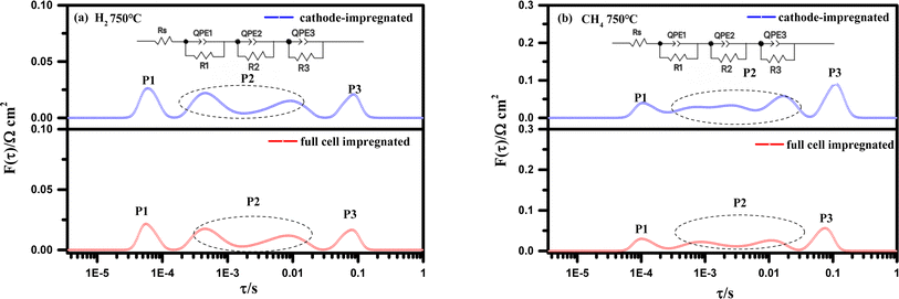
Electrochemical impedance spectra (EIS) obtained using the electrochemical workstation often exhibit flattened or overlapping semicircles, making analysis challenging. Distribution of relaxation times (DRT) analysis, however, can accurately capture the relationship between the time and frequency domains. It reveals the time required for a system to transition from one equilibrium state to another after a small perturbation, with different relaxation times corresponding to different reaction processes. This is useful for analyzing the electrochemical reactions occurring in the cell. Thus, DRT was applied to the impedance data collected at 750 °C, as shown in Fig. 4. Fig. 5 illustrates the DRT analysis results at 750 °C for both the fully impregnated and cathode-impregnated cells. The impedance spectra were fitted using an equivalent circuit model: Rs(R1/CPE1)(R2/CPE2)(R3/CPE3), where Rs represents the resistance from the electrolyte, leads, and ohmic effects, while the constant phase elements (CPE) account for the microstructural heterogeneity at the electrode–electrolyte interface. The DRT analysis further resolves the cell's primary electrochemical processes, with peaks labeled P1, P2, and P3 in order from low to high frequency. Specifically, the P1 peak is associated with gas diffusion, cathode O2 surface exchange, and solid-phase oxygen ion diffusion; the P2 peak reflects electrode polarization, primarily involving anode gas–solid interactions and gas diffusion; and the P3 peak is closely related to ion transport at the electrode–electrolyte interface.32,33
Comparing the DRT plots under H2 atmosphere in Fig. 5(a), the fully impregnated cell shows minimal changes in the areas of the P1 and P3 peaks compared to the cathode-impregnated cell, while the area of the P2 peak increases slightly. This is consistent with the impedance increase observed in Fig. 4(a) and (b), indicating that after full impregnation, the cell performance is primarily limited by electrode polarization processes and gas–solid interactions and gas diffusion at the anode surface. This phenomenon may be attributed to partial anode blockage caused by LSCFN impregnation, which hinders gas transport and increases overall impedance. Analyzing the results in Fig. 5(b) under CH4 as the fuel, we observe a slight reduction in the areas of the P1 and P3 peaks in the fully impregnated cell, with a significant decrease in the P2 peak area. Given that the test was conducted after the cell system reached thermal stability and steady-state performance, we infer that the cathode impregnation strategy may accelerate carbon deposition on the Ni anode due to prolonged and extensive direct contact with CH4 compared to the fully impregnated cell. This highlights the importance of auxiliary full impregnation methods in optimizing SOFC anode structures when using carbon-based fuels. This strategy effectively mitigates carbon deposition on Ni, resulting in a significant reduction in polarization resistance and overall enhancement of electrochemical performance. The DRT analysis elucidates the specific impact mechanisms of different impregnation strategies on the complex electrochemical processes within the cell, providing a theoretical foundation for the fine-tuning of cell structure and further performance optimization.
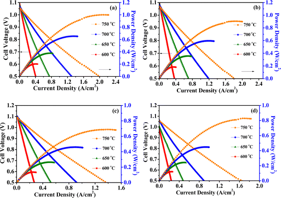
Fig. 6(a) and (b) depict the I–V–P spectra of cathode-impregnated and full cell impregnated LSCFN cells under H2 atmosphere. To ensure stable cell output, both cells were discharged at a current of 0.2 A cm−2 for 10 h before formal testing. The peak power density of cathode-impregnated MSCs at 750 °C is approximately 1015 mW cm−2, while that of full cell impregnated MSCs reaches 945 mW cm−2. Moreover, the power decreases as the temperature decreases. Cathode-impregnated MSCs perform better under H2 atmosphere. It is speculated that during full cell impregnation, the LSCFN nanoparticles covering some of the Ni particles hinder the catalysis of highly active Ni, leading to a decrease in the electrochemical performance of the cell.
Fig. 6(c) and (d) present the I–V–P spectra of cathode-impregnated and full cell impregnated LSCFN cells under CH4 atmosphere. Prior to formal testing, both cells were discharged at a current of 0.2 A cm−2 for 10 h. The results indicate that the peak power density of cathode-impregnated MSCs at 750 °C is approximately 700 mW cm−2, while that of full cell impregnated MSCs reaches 840 mW cm−2. The power density of the cells increases with temperature. Full cell impregnated LSCFN MSCs perform better under CH4 atmosphere. This is attributed to the fact that cathode impregnation leaves the anode unmodified. After introducing CH4 gas for a period of time, carbon accumulates on the surface of the Ni anode, reducing its catalytic activity and disrupting the triple-phase boundary conductivity, leading to decreased cell performance. Anode modification through full cell impregnation can reduce the contact between Ni and CH4 gas, and adsorb H2O and CO2 molecules, thereby reducing carbon accumulation and improving the electrochemical performance of the cell.34
Fig. 7 depicts the stability testing of the two types of cells under CH4 atmosphere, conducted at 750 °C with a constant current of 0.3 A cm−2. The initial output voltages were 0.8 V and 0.84 V, respectively. During the testing, the cathode-impregnated MSCs experienced a decay to approximately 0.69 V after 48 h of operation, whereas the full cell impregnated LSCFN cell maintained an output voltage above 0.80 V even after 100 h, indicating that full cell impregnation of LSCFN contributes to enhancing the stability of Ni/YSZ anode under CH4.
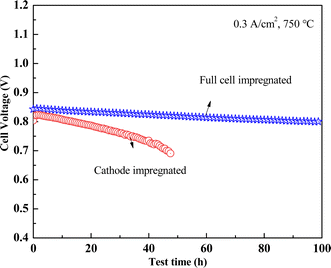 | ||
| Fig. 7 Stability test curves of cathode impregnated and full cell impregnated MSCs under CH4 atmosphere. | ||
4. Conclusions
In this study, LSCFN was prepared and used to obtain two types of integrated MSCs through cathode impregnation and full cell impregnation methods. XRD spectra indicated that after vacuum impregnation and sintering at 800 °C, the LSCFN solution formed a pure perovskite phase structure within the porous framework. Electrochemical performance tests of the MSCs showed that under H2 atmosphere, the MSCs with cathode impregnation exhibited better electrochemical performance compared to those with full cell impregnation. In the anodes of the full cell impregnated cells, LSCFN partially adhered to the Ni surface, reducing the catalytic activity of Ni and hindering the direct contact between H2 molecules and the Ni particles and the triple-phase boundaries. Under CH4 atmosphere, the full cell impregnated MSCs performed better than those with cathode impregnation. The lack of anode modification in the cathode impregnated cells led to carbon deposition on the Ni surface, causing rapid performance degradation. In contrast, the modified anode with a layer of LSCFN nanoparticles reduced the contact between the anode Ni and CH4 gas, thereby reducing carbon deposition and enhancing the electrochemical performance of the cell.The full cell impregnation of LSCFN in cell production achieved integrated MSCs cathode preparation and anode modification, significantly simplifying the fabrication process. The four-layer integrated structure supported by metal also reduced the constraints on the thermal expansion coefficient of the cathode material, enabling low-temperature sintering of the cathode and expanding the range of material choices. This study demonstrated the feasibility of this approach, providing a theoretical basis for future research and promoting the practical application of metal-supported solid oxide fuel cells.
Data availability
All relevant data are within the manuscript.Conflicts of interest
There are no conflicts of interest to declare.Acknowledgements
This work was supported by the National Natural Science Foundation of China (52202238), the Jilin Scientific and Technological Development Program (20220101097JC) and the Scientific Research Project of Jilin Provincial Department of Education (JJKH20230515KJ).References
- Y. Liu, L. W. Zuo, Y. L. Ye, C. Jiang, D. Zheng, C. L. Liu, B. Y. Wang and X. Y. Wang, RSC Adv., 2023, 13, 33430–33436 RSC.
- A. Hauch, R. Kungas, P. Blennow, A. B. Hansen, J. B. Hansen, B. V. Mathiesen and M. B. Mogensen, Science, 2020, 370, eaba6118 CrossRef CAS PubMed.
- V. V. Krishnan, Wires Energy Environ., 2017, 6, 1–35 Search PubMed.
- H. Xu, Y. Han, J. Zhu, M. Ni and Z. Yao, Energy Rev., 2024, 3, 100051 CrossRef.
- M. M. Welander, B. X. Hu and M. C. Tucker, Int. J. Hydrogen Energy, 2022, 47, 11261–11269 CrossRef CAS.
- M. C. Tucker, J. Power Sources, 2010, 195, 4570–4582 CrossRef CAS.
- S. Belakry, A. Rolle, E. Capoen, R. N. Vannier and D. Fasquelle, ECS J. Solid State Sci. Technol., 2022, 11, 023014 CrossRef CAS.
- M. C. Tucker, ECS Trans., 2019, 91(1), 877–885 CrossRef.
- F. Y. Shen, M. Reisert, R. F. Wang, P. Singh and M. C. Tucker, ACS Appl. Energy Mater., 2022, 5, 9383–9391 CrossRef CAS.
- F. Liu, D. Diercks, A. M. Hussain, N. Dale, Y. Furuya, Y. Miura, Y. Fukuyama and C. C. Duan, ACS Appl. Mater. Interfaces, 2022, 14, 53840–53849 CrossRef CAS.
- N. Xu, D. Geng, X. F. Tong, M. Z. Sun and Z. L. Xu, Solid State Ionics, 2020, 358, 115482 CrossRef CAS.
- Y. Y. Liu, D. Yan, N. Q. Li, L. C. Jia and J. Li, Fuel, 2024, 368, 131626 CrossRef CAS.
- S. Bassil, T. Caillot, F. J. C. S. Aires, F. C. Meunier and A. Kaddouri, React. Chem. Eng., 2024, 9, 1251–1260 RSC.
- T. Chen, H. L. Zhang, G. Z. Zheng, Q. Xue, Z. Z. Huang, Y. C. Zhou and S. R. Wang, Membranes, 2024, 14, 44 CrossRef CAS PubMed.
- J. Y. Kim, L. Mastropasqua, A. Saeedmanesh and J. Brouwer, Energy Convers. Manage., 2024, 308, 118405 CrossRef CAS.
- A. N. Tabish, L. Y. Fan, I. Farhat, M. Irshad and S. Z. Abbas, J. Power Sources, 2021, 513, 230564 CrossRef CAS.
- M. M. Welander, B. X. Hu, S. Belko, K. X. Lee, P. K. Dubey, I. Robinson, P. Singh and M. C. Tucker, Int. J. Hydrogen Energy, 2023, 48, 1533–1539 CrossRef CAS.
- A. Hagen, D. Tasca, A. D. Faria, F. Capotondo, R. Caldogno, B. R. Sudireddy and X. Sun, J. Electrochem. Soc., 2024, 171, 044505 CrossRef.
- Z. Q. Xu, X. Y. Hu, Y. H. Wan, S. S. Xue, S. W. Zhang, L. J. Zhang, B. Z. Zhang and C. G. Xia, Electrochim. Acta, 2020, 341, 136067 CrossRef CAS.
- W. Fan, Z. Sun, Y. Bai, K. Wu, J. Zhou and Y. Cheng, J. Power Sources, 2020, 456, 228000 CrossRef CAS.
- P. Li, D. Runze and Y. C. Wang, Renew. Energy, 2021, 177, 387–396 CrossRef CAS.
- Z. B. Yang, Y. Chen and N. Xu, J. Electrochem. Soc., 2015, 162, F718–F721 CrossRef CAS.
- N. Xu, T. L. Zhu, Z. B. Yang and M. F. Han, Electrochim. Acta, 2018, 265, 259–264 CrossRef CAS.
- N. A. Merino, B. P. Barbero, P. Ruiz and L. E. Cadús, J. Catal., 2006, 240, 245–257 CrossRef CAS.
- S. Dwivedi, Int. J. Hydrogen Energy, 2020, 45, 23988–24013 CrossRef CAS.
- A. K. U, A. Sethi, R. M. Lawrence and V. M. Dhavale, Int. J. Hydrogen Energy, 2021, 46, 34701–34712 CrossRef CAS.
- X. M. Xu, Y. L. Pan and Z. P. Shao, Electrochim. Acta, 2016, 219, 553–559 CrossRef CAS.
- Z. Jiang, X. Liu, X. Z. Liu, S. Huang, Y. Liu, Z. C. Yao, Y. Zhang, Q. H. Zhang, L. Gu, L. R. Zheng, L. Li, J. Zhang, Y. Fan, T. Tang, Z. Zhuang and J. S. Hu, Nat. Commun., 2023, 14, 1–12 CAS.
- M. Ghaffari, H. Huang and M. Shannon, CrystEngComm, 2012, 14, 7487–7492 RSC.
- N. Xu, T. L. Zhu, Z. B. Yang and M. F. Han, J. Mater. Sci. Technol., 2017, 33, 1329–1333 CrossRef CAS.
- Y. Y. Liu, J. Luo, L. L. Zhang, D. Yan, L. C. Jia and J. Li, Int. J. Hydrogen Energy, 2024, 62, 652–658 CrossRef CAS.
- H. Zhang, T. Chen, Z. Huang, G. Hu, J. Zhou and S. Wang, Int. J. Hydrogen Energy, 2022, 47, 18810–18819 CrossRef CAS.
- Z. Huang, Y. Yang, H. Lv, C. Shi, Y. Ling, J. Zhou and S. Wang, J. Power Sources, 2022, 521, 18810–18819 CrossRef.
- S. H. Woo, S. W. Baek, D. S. Park, K. E. Song, H. Schlegl, J. Y. Park and J. H. Kim, J. Alloys Compd., 2021, 854, 157250 CrossRef CAS.
Footnote |
| † Electronic supplementary information (ESI) available. See DOI: https://doi.org/10.1039/d4ra04253k |
| This journal is © The Royal Society of Chemistry 2024 |

