DOI:
10.1039/D4RA04704D
(Paper)
RSC Adv., 2024,
14, 25975-25985
Nucleation and growth process of a softened-spark layer during microarc oxidation on a selective laser melted Ti alloy
Received
28th June 2024
, Accepted 26th July 2024
First published on 19th August 2024
Abstract
A two-step method for preparing composite coatings with different composition on Ti alloys using softened spark microarc oxidation technology was proposed. The nucleation and growth processes of a softened spark layer, as well as the influence of softened sparks on the deposition of anions in electrolytes, were studied. The results show that the process voltage of the softened spark discharge on the selective laser-melted Ti6Al4V alloy was lower than the breakdown voltage of its anodic oxide film. The softened sparks prioritized nucleation at the coating/substrate interface in the initial spark discharge area rather than in the microarc discharge area. On one hand, the softened spark layer grew towards the Ti6Al4V substrate, and on the other hand, the molten oxide generated by the softened sparking was transferred into the external porous layer. The softened sparks generated inside the coating promoted the rutile phase formation and linear growth in the thickness of the softened spark layer. Ca and P are mainly distributed in the external porous layer or at the interface between the softened-spark and external porous layers. Nevertheless, softened sparking had little effect on the initial micro/nanoporous structures of the coatings.
1. Introduction
Titanium (Ti) and its alloys have been widely used in the medical field because of their non-toxicity, antibacterial properties, and biocompatibility.1 Various types of Ti alloys can be used for clinical treatments, among which Ti6Al4V alloys are the most widely used biomedical implant materials owing to their favorable strength, high corrosion and wear resistance, and acceptable biocompatibility.2 However, the performance of many metal (including Ti6Al4V alloy) biomedical implants is inherently limited by the mismatch of mechanical properties between the metal and the biological bone tissue it promotes.3 Nowadays, it is widely recognized that additive manufacturing can enhance their mechanical properties tailored towards biomedical applications.4,5 However, implants produced through additive manufacturing methods face performance-related challenges, particularly biocompatibility.6 Consequently, an effective approach for overcoming these challenges involves surface modification using advanced coatings.6,7
Microarc oxidation (MAO), also known as plasma electrolytic oxidation (PEO), is an effective surface modification technique for producing oxide-ceramic coatings on metals such as Ti, aluminium (Al), and magnesium (Mg).8,9 It involves high-voltage oxidation beyond the dielectric breakdown that occurs at the electrolyte/oxide/metal interface.10 Because of the high plasma discharge temperature, the anodic oxide film on the metal transforms into a ceramic layer, exhibiting excellent corrosion and wear resistance.11 Notably, the co-deposition of composition into MAO coatings through electrolytes has been a hot topic in the biomedical field. Zhang et al.12 found that Ca/P/Zn-doped coatings improved the cell viability of preosteoblast MC3T3-E1 cells and macrophage RAW264.7 cells, and higher cell viability was observed on the coatings with higher Zn concentration. Liu et al.13 doped Zn and Sr into coatings on Ti alloy implants using one-step MAO technology and found that the Zn/Sr-doped MAO coatings exhibited good antibacterial activity against Staphylococcus aureus and Porphyromonas gingivalis. Wu et al.14 proposed that Cu-doped MAO coatings are capable of enhancing the bone repair/regeneration, angiogenesis, and antibacterial capability. Zhao et al.15 reported that Mg/Cu/F-doped MAO coatings promote the adhesion, proliferation, differentiation, mineralization, and apoptosis of MC3T3-E1 osteoblasts. However, Fattah-Alhosseini et al.16 reported that the addition of particles to the electrolyte results in strong antibacterial and biological activity but also changes the designed micro/nanostructure of the MAO coatings. This indicates that achieving multicomponent co-doping within MAO coatings faces significant difficulties.
Consequently, a mode of “softened spark” during the MAO process is considered a potential solution for achieving co-doped multicomponent and micro/nano porous structure.17,18 Zhai et al.19 pointed out that softened sparks have a minimal impact on the external micro/nanoporous structure of the initial MAO coating. Wang et al.20 found that the effect of softened sparks on the morphology of MAO coatings weakened, and the amounts of calcium (Ca) and phosphate (P) co-deposited in the coating increased with an increase in the negative/positive charge ratio. However, a lack of understanding of the mechanism of the soft sparking during the MAO limits its industrial applicability.20 Therefore, this study proposes a two-step method for preparing composite coatings with different composition on Ti alloys using softened spark MAO technology. The nucleation and growth process of softened sparks and the influence of softened sparks on the deposition of anions in electrolytes were investigated.
2. Materials and methods
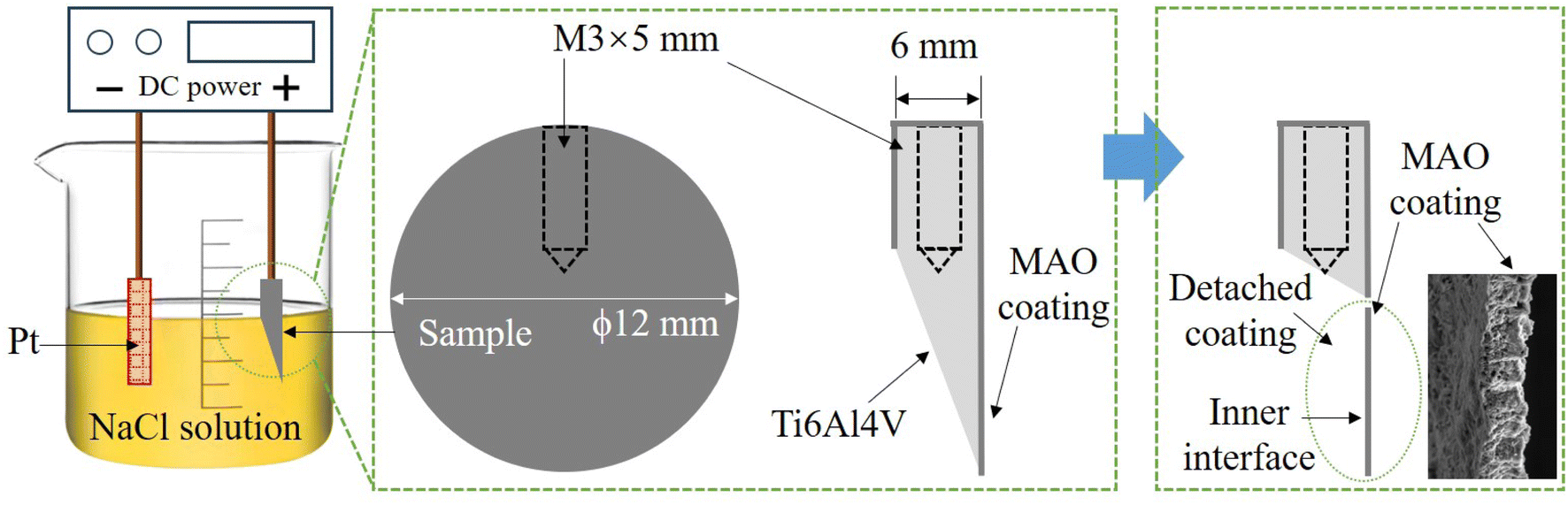
A cylindrical specimen with a diameter of 12 mm and a thickness of 6 mm was prepared by selective laser melting (SLM) (AM250, Renishaw Co., Ltd, England) using Ti alloy powder with a composition of 6.25% Al, 4.16% V, 0.2% Fe, 0.0068% Ca, and Ti (balance, mass fraction). As shown in Fig. 1, a tapped hole with a diameter of 3 mm was made on the side of the cylinder to connect it to the anode of the power supply. Next, MAO and softened-spark MAO treatments were performed on the samples in two different electrolytes. Step 1, an alternating polarity power supply (ANS 7505, Ansy Power Supply Co., Ltd, China) was used to perform MAO on all samples in a mixed electrolyte of 0.09 mol per L Na2B4O7·10H2O and 0.01 mol per L Na2SiO3·9H2O for 300 s. A positive current density of 10 A dm−2, a positive pulse with a current density of 10 A dm−2, a duration period of 500 μs, and a rest period of 4500 μs was used. The electrolyte temperature was maintained at approximately 10 °C using a thermostatic system. Step 2, a mixed electrolyte of 0.16 mol per L EDTA·2Na, 0.16 mol per L Ca(CH3COO)2·H2O and 0.18 mol per L NH4H2PO4 was used to perform softened spark MAO on the samples pretreated with MAO. During the softened spark MAO process, a positive pulse with a current density of 5 A dm−2, a duration period of 1000 μs, and a rest period of 5000 μs were used, and a negative pulse with a current density of 12.5 A dm−2, a duration period of 500 μs, and a rest period of 2000 μs were set. The electrolyte temperature was also maintained at approximately 10 °C. The times for softened-spark MAO were set to 0, 200, 600, 1000, 1800, and 2400 s.
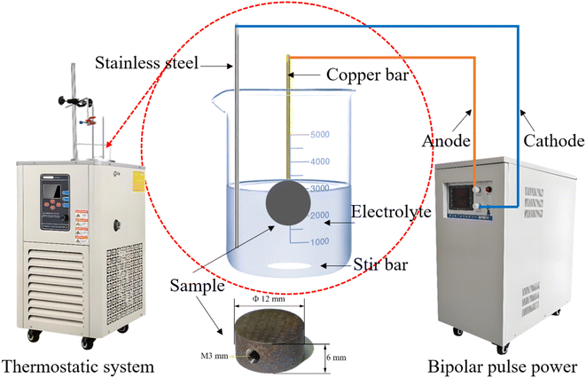 |
| | Fig. 1 Schematic illustration of the experimental device and the size of sample. | |
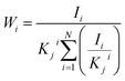
During the MAO and softened spark MAO processes, the voltage-time response was recorded using an alternating polarity power supply, and the morphologies of the microarcs and sparks were captured using high-speed cameras (Phantom VEO710L, Vision Research Inc.). After softened spark MAO treatment, the thicknesses of the coatings on the samples were measured using a coating thickness gauge (DUALSCOPE MP0, Fischer, Germany). Subsequently, the micro-morphologies of the coatings were observed using scanning electron microscopy (SEM) (MIRA4 LMH, TESCAN, Czech Republic) and transmission electron microscopy (TEM) (JEM-F200, JEOL, Japan). In addition, the phase compositions of the coatings were analyzed using X-ray diffraction (XRD) technique (Empyren, PANalytical, Netherlands) with a CuKα radiation at 45 kV and 40 mA for 2θ = 20–90° at a scan speed of 0.1° s−1. Compositions of the coatings were detected using energy dispersive X-ray spectroscopy (EDS) (One Max 50, TESCAN, Czech Republic). The mass fractions of the phases were calculated using eqn (1):20,21
| |
 | (1) |
where
Wi is the mass percentage of phase
I,
Ii is the diffraction intensity of the strongest diffraction peak of phase
I,
Kji is the diffraction intensity of the strongest diffraction peak after mixing phase
I and reference phase
J in a 1
![[thin space (1/6-em)]](https://www.rsc.org/images/entities/char_2009.gif)
:
1 mode, the value of
Kji can be obtained from the PDF card.
Moreover, an electrochemical method was designed to separate the coating from the substrate, which allowed for good observation of the morphology of the interface between the coating and substrate. Fig. 2 shows a schematic diagram of the electrochemical method. First, a portion of the sample was cut to expose the Ti-alloy substrate. The sample was immersed in 1 mol per L NaCl solution and connected to the positive electrode of the DC power source. The negative electrode was connected to the platinum electrode. Next, the Ti-alloy was dissolved in an electrochemical reaction, resulting in the exposure of the inside interface of the coating.
 |
| | Fig. 2 Schematic diagram of the electrochemical process. | |
3. Results and discussion
3.1 Voltage-time response
Fig. 3 shows the spark morphology at each stage and the voltage-time response of the MAO process on the SLM-formed Ti6Al4V alloy. Sodium silicate was used as the electrolyte for the MAO treatment. In this electrolyte, three phenomena-anodic oxidation, spark discharge, and micro-arc discharge-occurred successively on the samples. First, numerous bubbles appeared on the surfaces of the samples, and the voltage increased linearly and rapidly; however, no sparks were observed. Some studies have referred to this stage as the anodic oxidation stage (Stage I).19,20,22 Subsequently, the voltage reached approximately 218 V when the time exceeded 7 s, and a few white sparks appeared on the samples, accompanied by a squeaking sound arising from the arc blasting, indicating that the anodic oxide film broke down. Some studies have referred to the white spark discharge process as the spark discharge stage (Stage II).22,23 Over time, the number of discharge sparks gradually decreases; however, their intensity gradually increases, and their color changes from white to orange. Some studies have referred to the orange microarc discharge process as the microarc discharge stage (Stage III).23 The other is a Ca/P electrolyte, which is used for softened spark MAO treatment. When the samples treated with MAO in the Na2SiO3 electrolyte for 300 s were subjected to softened spark MAO in the Ca/P electrolyte, the process voltage dropped sharply from the previous highest value of 424 V to approximately 150 V and remained between 140 and 150 V in the following process. During this process (Stage IV), the spark intensity appearing on the samples was always extremely weak; this is referred to as a softened spark in this study (this term has also been reported in other papers).17,19 It is worth noting that the voltage of the softened spark discharge on the SLM-formed Ti6Al4V alloy was lower than the breakdown voltage of the anodic oxide film, but close to the breakdown voltage of the anodic oxide film on the forged Ti6Al4V alloy (approximately 140–150 V, reported in other papers24,25). This phenomenon indicates that the microstructure of the SLM-formed Ti6Al4V alloy has a significant impact on the microarc discharge but has almost no effect on the softened spark discharge.
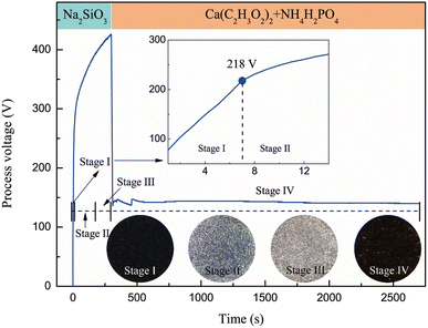 |
| | Fig. 3 Sparks morphology at each stage and voltage-time response of the MAO process on SLM formed Ti6Al4V alloy. | |
3.2 Microscopic morphology and composition of coatings
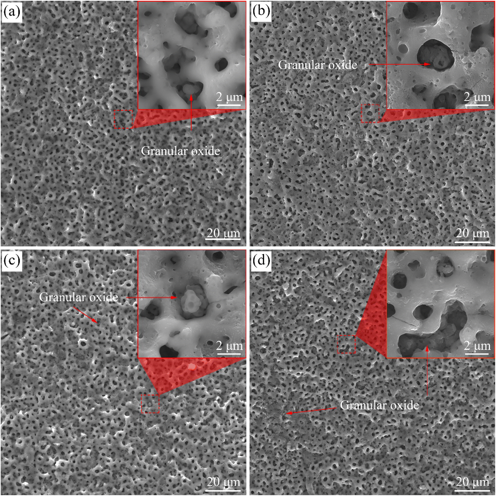
Fig. 4 shows the surface morphologies of the coatings on the samples treated with softened spark MAO for various times. Amounts of pores with a diameter of 0.5–1 μm and 2–5 μm were observed in the four coatings. The former was formed in the spark discharge stage (hereafter referred to as spark pores), whereas the latter was formed in the microarc discharge stage (hereafter referred to as microarc pores). A typical volcanic crater morphology was observed around the microarc pores, which were formed by the accumulation of molten oxides during microarc discharge. As shown in Fig. 4(a), oxide granules were observed in some microarc pores, but not in most pores. Moreover, the surface of the molten oxide that accumulated around the microarc pores was relatively smooth. It can be inferred that these oxide granules were generated by softened spark discharge. Significantly, a large number of bubble pores appeared on the accumulated oxides near the volcanic craters (Fig. 4(b)). In addition, some oxide granules are clearly observed in the microarc pores, and there are many bubble pores on the oxide granules. These phenomena are related to softened spark discharge. As the time increases to 1200 s, as shown in Fig. 4(c), some microarc pores are blocked by the oxide granules produced by the softened spark discharge. Furthermore, the number of bubble pores on the accumulated oxides near the volcanic craters decreased slightly. As time progressed, as shown in Fig. 4(d), oxide granules were generated by the softened spark discharge and distributed in local areas on the coating. This indicates that the softened sparks prioritize nucleation in local areas. Overall, the softened sparks had little effect on the microarc pores in the coating.
 |
| | Fig. 4 Surface morphology of the coatings on samples treated with softened spark MAO at (a) 200 s, (b) 600 s, (c) 1200 s, and (d) 1800 s. | |
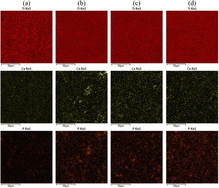
Fig. 5 shows the EDS mapping of the MAO coatings on the Ti6Al4V samples treated with softened spark MAO for different durations, and Table 1 lists the contents of the main elements deposited on the coatings. As shown in Fig. 5(a), small amounts of Ca and P, as well as a significant amount of Si, were detected on the coating surface. These elements originate from the electrolytes. As the softened-spark MAO time increased to 600 s, as shown in Fig. 5(b), the Ca and P contents distributed on the coating surface increased slightly. This was speculated to be related to the bubble pores generated by the softened spark discharge in the accumulated oxide. As time progressed, as shown in Fig. 5(c) and (d), the Ca and P contents on the MAO coating surface decreased slightly. It is speculated that this is due to a slight decrease in the number of bubble pores generated by the softened spark discharge.
 |
| | Fig. 5 EDS mapping results of the MAO coatings on the Ti6Al4V samples treated with softened spark MAO at (a) 200 s, (b) 600 s, (c) 1200 s, and (d) 1800 s. | |
Table 1 Mass variation of the main elements deposited on the MAO coatings
| Treatment time (s) |
Mass variation (wt%) |
| Ti |
O |
Al |
V |
Ca |
P |
Si |
| 200 |
39.51 |
47.63 |
2.66 |
1.36 |
0.36 |
0.32 |
8.17 |
| 600 |
36.48 |
51.90 |
2.43 |
1.21 |
0.43 |
0.71 |
6.83 |
| 1200 |
39.06 |
48.58 |
2.60 |
1.29 |
0.42 |
0.47 |
7.58 |
| 1800 |
39.30 |
48.11 |
2.60 |
1.30 |
0.43 |
0.52 |
7.74 |
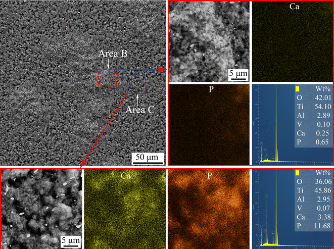
An electrochemical method was designed to detach the MAO coatings from the substrate. The morphology and elemental distribution of the inner interface of the coating on the Ti6Al4V sample treated with softened spark MAO for 200 s are shown in Fig. 6. There are two areas on the inner interface of the coating, namely area B containing a large number of oxide granules and area C containing many microarc pores with a diameter of 2–5 μm. Some spark pores with a diameter of 0.5–1 μm can also be observed in area B. This indicates that the softened spark discharge prioritizes nucleation within the spark discharge area. The EDS mapping results showed that there were many Ca and P elements in area C but very few in area B. It can be explained that the electrolyte anions (Ca2+ and PO43−) did not pass through the softened spark layer and failed to reach the coating/substrate interface; however, its oxide deposited in the microarc pore.
 |
| | Fig. 6 Surface morphology and elemental distribution of the detached coating formed on the sample treated with softened spark MAO at 200 s. | |
Fig. 7 shows the cross-sectional morphology of the coatings on the Ti6Al4V samples treated with softened spark MAO at different times. As shown in Fig. 7(a), the coatings included a barrier layer at the coating/substrate interface, an intermediate softened spark layer, and an external porous layer. Within the softened spark layer, smaller pores with a diameter less than 0.5 μm were observed than those obtained from the first microarc discharge. As the treatment time increased, as shown in Fig. 7(b) and (c), the softened spark layer grew towards the Ti6Al4V substrate, and the molten oxide generated by the softened spark discharge was transferred into the external porous layer. It can be seen that the boundary between the external porous layer and the intermediate softened-spark layer is difficult to distinguish. The area covered by the molten oxide generated by the softened spark discharge is referred to as the softened spark layer. As shown in Fig. 7(d), the softened spark layer completely covers the external porous layer. It is worth noting that the coating/substrate interface gradually changed from relatively flat to uneven with increasing treatment time. This also confirms that the softened spark discharge preferentially nucleated in local areas and grew towards the substrate. The results of the EDS line scanning showed that Ca and P were mainly distributed on the oxide in the external porous layer or at the interface between the softened spark layer and the external porous layer, but there was almost no presence inside the softened spark layer. This is because most anions in the electrolyte are low-mobility species26 and cannot diffuse completely through the dense oxide layer. Therefore, these electrolyte anions are transformed into oxides and deposited outside the channel of the softened spark discharge during softened spark discharge. This inference will be further validated in the following experiments.
 |
| | Fig. 7 Cross-sectional morphology of the coatings on samples treated with softened spark MAO at (a) 200 s, (b) 600 s, (c) 1200 s, and (d) 1800 s. | |
Fig. 8 shows a bright-field TEM image, high-magnification image, selected area diffraction patterns, and the elemental distribution of the coating on the Ti6Al4V samples treated with softened spark MAO for 1800 s. As shown in Fig. 8(a), three bright-field TEM images were spliced together to show the cross-sectional morphology of the coating. A dense barrier layer with a thickness of less than 500 nm was observed at the coating/substrate interface. The high-magnification image and selected area diffraction patterns of area B show that the dense barrier layer is composed of amorphous oxide and a very small number of nanocrystals (Fig. 8(b)). In the middle area of the coating, there are some pores with a diameter of about 0.5 μm and a large number of pores with a diameter smaller than that. Based on the previous analysis, we speculated that these areas were the areas of spark discharge and softened spark discharge. The high-magnification image and selected area diffraction patterns of area C show a large number of rutile-phase nanocrystals in the softened spark layer (Fig. 8(c)). The result of the EDS mapping in area D shows the amounts of Ca and P deposited in the external area of the softened spark layer (Fig. 8(d)). The high-magnification image and selected area diffraction patterns of area E show a large amorphous region in the external area of the softened spark layer (Fig. 8(e)). Therefore, the electrolyte anions were mainly deposited in the external region of the softened spark layer in the form of amorphous oxides.
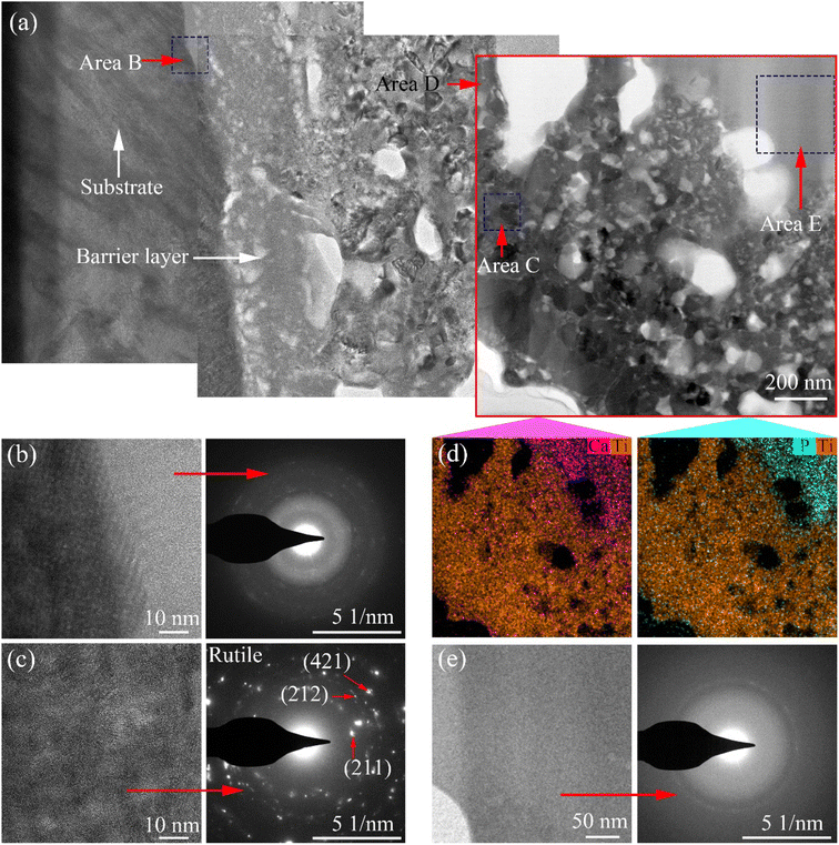 |
| | Fig. 8 Bright-field TEM image (a), high-magnification image, diffraction patterns and elemental distribution of the selected (b) area B, (c) area C, (d) area D, (e) area E, for the sample treated with softened spark MAO at 1800 s. | |
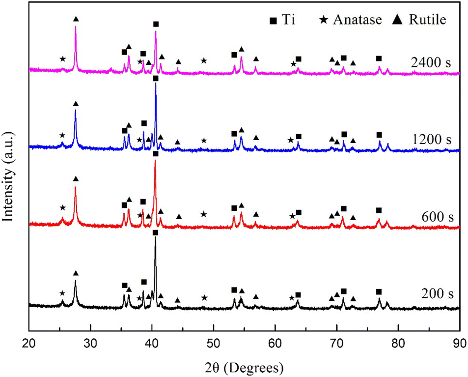
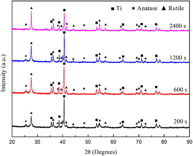
Fig. 9 shows the XRD spectra of the coatings on the Ti6Al4V samples treated with softened spark MAO at different times. The phase contents calculated based on the spectra are listed in Table 2. The results showed that the MAO coatings were mainly composed of rutile and anatase phases. As the duration of the softened spark treatment increased, the rutile phase content gradually increased, whereas the anatase phase content remained unchanged. This indicates that the softened spark discharge generated inside the coating promotes the formation of the rutile phase, which is due to the fact that temperature decreases at a lower rate inside the coating. In addition, the Ti phase content gradually decreased, which is consistent with the growth mechanism of the coating thickness.
 |
| | Fig. 9 XRD spectrum of the coating on the Ti6Al4V treated with softened spark MAO at different times. | |
Table 2 Mass variation of the phases during the softened spark MAO process
| Treatment time |
Mass variation (wt%) |
| Rutile |
Anatase |
Ti |
| 200 s |
18.51 |
4.21 |
77.27 |
| 600 s |
24.06 |
4.23 |
71.71 |
| 1200 s |
24.20 |
3.99 |
71.81 |
| 2400 s |
35.35 |
3.97 |
60.68 |
3.3 Surface roughness and thickness of coatings
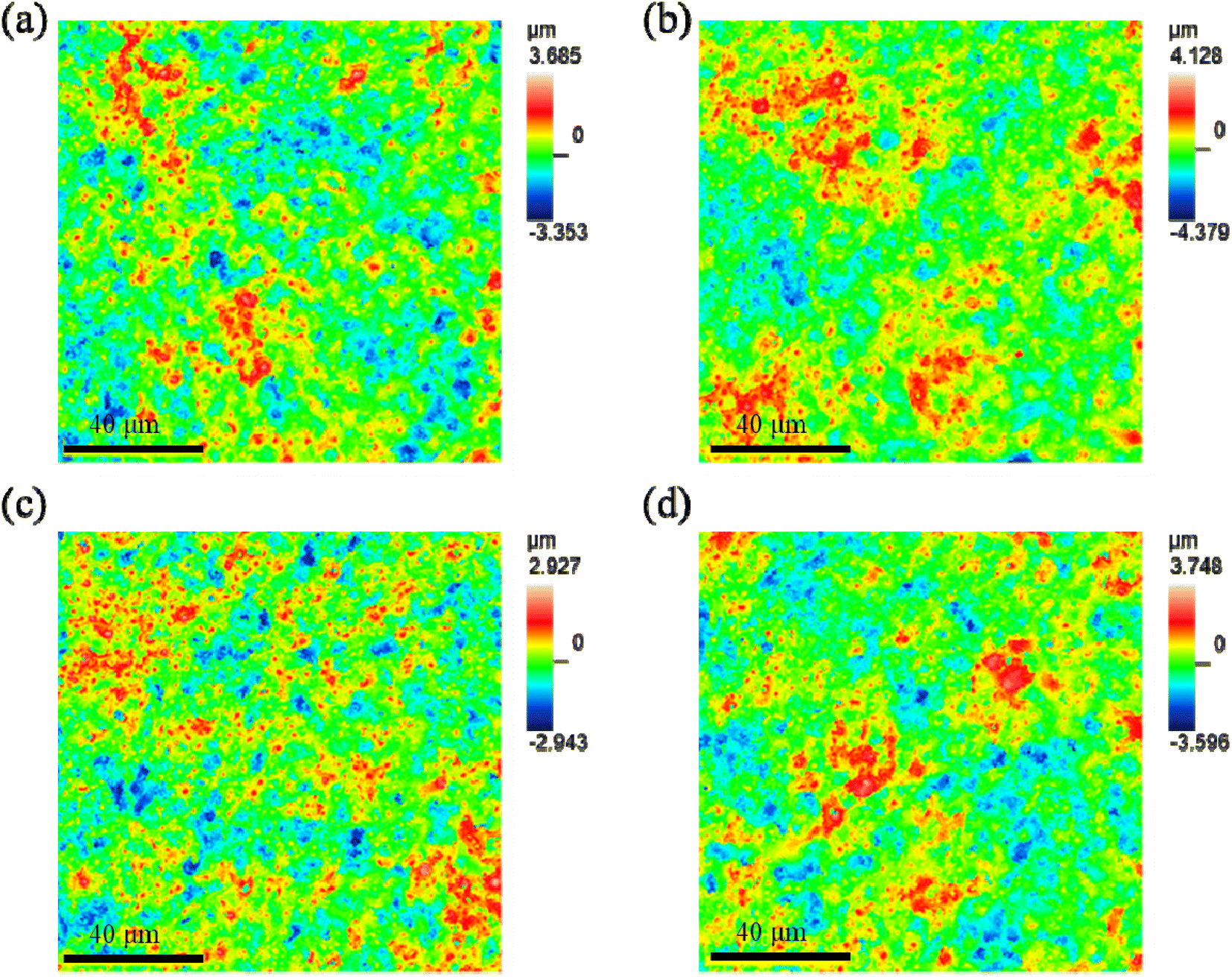
Fig. 10 shows the profile topography of the coating on the Ti6Al4V samples treated with softened spark MAO at different times. The root-mean-square height (Sq), arithmetic average height (Sa), maximum peak height (Sp), maximum valley depth (Sv), degree of skewness (Ssk), and area ratio of interface expansion (Sdr) of the coating surface were obtained and are listed in Table 3. A comparison of the results shows no significant difference in the surface roughness of the coatings. This can be explained by the softened sparks that mainly formed inside the coating, which had little impact on the external morphology of the coating. However, the coatings on the samples treated with softened spark MAO for 600 and 1800 s exhibited smaller variations in the Sp and Sv than the other two samples. This is related to the deposition of granular oxides generated by the softened spark discharge in the microarc pores and the formation of softened spark pores on the molten oxides.
 |
| | Fig. 10 Profiles topography of the coating on the Ti6Al4V samples treated with softened spark MAO at (a) 200 s, (b) 600 s, (c) 1200 s, and (d) 1800 s. | |
Table 3 Surface roughness of the MAO coatings obtained in different electrolytes
| Sample |
Sq (μm) |
Sa (μm) |
Sp (μm) |
Sv (μm) |
Sdr (%) |
| 200 |
0.745 |
0.591 |
3.247 |
2.922 |
36.4 |
| 600 |
0.826 |
0.661 |
3.685 |
3.948 |
37.539 |
| 1200 |
0.656 |
0.521 |
2.599 |
2.596 |
35.44 |
| 1800 |
0.782 |
0.622 |
3.371 |
3.191 |
36.737 |
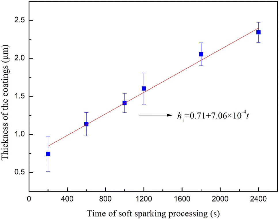
Fig. 11 shows the thicknesses of the coatings on the Ti6Al4V samples treated with softened spark MAO for 200, 600, 1000, 1200, 1800, and 2400 s. After fitting the thickness data, it was found that the coating thickness increased linearly, and the growth of the coatings can be described by the following equation:
| | |
h = 7.06 × 10⁻⁴t + 0.71
| (2) |
where
t represents the treatment time of the softened spark MAO during step 2, and
h represents the total thickness, including the thickness promoted by the softened spark discharge and the thickness generated by the microarc discharge. Because the coatings generated by the microarc discharge on the four samples are the same, it is inferred that the thickness of the softened spark layer also increases linearly with the treatment time. Some reports have indicated that the thickness of MAO coatings increases linearly with time. This indicates that the softened spark was essentially a type of microarc. However, the former has extremely low strength, produces more rutile, and promotes a slower increase in coating thickness.
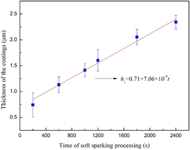 |
| | Fig. 11 Thicknesses of the coating on the Ti6Al4V treated with softened spark MAO at different times. | |
4. Conclusion
MAO and softened-spark MAO treatments were performed on the SLM-formed Ti6Al4V alloy in two different electrolytes. The effects of softened sparks on the micro/nanostructure and composition of MAO coatings were investigated. The primary findings of this study are summarized as follows:
(1) The voltage of the softened spark discharge on the SLM-formed Ti6Al4V alloy was lower than the breakdown voltage of the anodic oxide film, but close to the breakdown voltage of the anodic oxide film on the forged Ti6Al4V alloy. This phenomenon indicates that the microstructure of the SLM-formed Ti6Al4V alloy has a significant impact on the microarc discharge but has almost no effect on the softened spark discharge.
(2) The softened spark discharge prioritizes nucleation at the coating/substrate interface in the spark discharge area rather than in the microarc discharge area. As the treatment time increased, the softened spark layer grew towards the Ti6Al4V substrate, and the molten oxide generated by the softened spark discharge was transferred into the external porous layer. The area covered by molten oxide generated by the softened spark discharge is referred to as the softened spark layer. Because of the growth of the softened spark layer inside the coating, the softened spark discharge had little effect on the initial micro/nanoporous surface structure of the coating. Moreover, the thickness of the softened spark layer increased linearly with the treatment time, which is consistent with the typical trend of thickness growth in MAO coatings. This indicates that the softened spark was essentially a type of microarc.
(3) The primary distribution of Ca and P is concentrated within the oxide of the external porous layer, or at the interface between softened spark layer and external porous layer. Notably, however, within the softened spark layer itself, Ca and P are nearly absent. As the duration of the softened spark treatment increased, the rutile phase content gradually increased, whereas the anatase phase content remained unchanged. This indicated that the softened spark discharge generated inside the coating promoted the formation of the rutile phase.
Data availability
The authors confirm that the data supporting the findings of this study are available within the article.
Conflicts of interest
There are no conflicts of interest to declare.
Acknowledgements
This work was supported by the following funds: (1) Natural Science Foundation of Hunan Provincial (2022JJ50182); (2) Outstanding Youth Project of Hunan Provincial (23B0714); (3) Key Innovation Project of Shaoyang (2023GZ2001).
References
- H. Huang, Y. Chang and M. T. Tsai, et al., Laser texturing and oxidation of TiZrTa thin films to improve the biocompatible performance of titanium alloys, Surf. Coat. Technol., 2024, 482, 130734 CrossRef CAS.
- G. Wei, M. Tan and S. Attarilar, et al., An overview of surface modification, A way toward fabrication of nascent biomedical Ti–6Al–4V alloys, J. Mater. Res. Technol., 2023, 24, 5896–5921 CrossRef CAS.
- E. Alabort, Y. T. Tang and D. Barba, et al., Alloys-by-design: A low-modulus titanium alloy for additively manufacture d biome dical implants, Acta Mater., 2022, 229, 117749 CrossRef CAS.
- J. Su, F. Jiang and J. Teng, et al., Recent innovations in laser additive manufacturing of titanium alloys, Int. J. Extreme Manuf., 2022, 6, 032001 CrossRef.
- F. Anene, J. Aiza and I. Zainol, et al., Additively manufactured titanium alloys and effect of hydroxyapatite coating for biomedical applications: A review, Proc. Inst. Mech. Eng., Part L, 2020, 234(11), 1450–1460 CAS.
- A. Kumar and G. Singh, Surface modification of Ti6Al4V alloy via advanced coatings: Mechanical, tribological, corrosion, wetting, and biocompatibility studies, J. Alloys Compd., 2024, 989, 174418 CrossRef CAS.
- G. Wei, M. Tan and S. Attarilar, et al., An overview of surface modification, A way toward fabrication of nascent biomedical Ti–6Al–4V alloys, J. Mater. Res. Technol., 2024, 24, 5896–5921 CrossRef.
- K. Liu, J. Qi and H. B. Jiang, et al., Advances in amelioration of plasma electrolytic oxidation coatings on biodegradable magnesium and alloys, Heliyon, 2024, 10(4), E24348 CrossRef PubMed.
- F. Simchen, M. Sieber and A. Kopp, et al., Introduction to Plasma Electrolytic Oxidation—An Overview of the Process and Applications, Coatings, 2020, 10(7), 628 CrossRef CAS.
- D. Veys-Renaux, K. Guessoum and E. Rocca, Micro-Arc Oxidation Treatments on Zn, Meet. Abstr., 2014, MA2014-02, 773 CrossRef.
- Y. Zhong, X. Zhang and Y. Wu, Plasma electrolytic oxidation ceramic coatings proceed by porous anodic film, J. Alloys Compd., 2020, 812, 152098 CrossRef.
- Z. Zhang, T. Huang and D. Zhai, et al., Study on Zn-doped antibacterial bioactive coatings on Ti6Al4V titanium alloy surfaces by micro-arc oxidation, Surf. Coat. Technol., 2023, 467, 129724 CrossRef CAS.
- L. Liu, F. Ma and P. Liu, et al., Preparation and antibacterial properties of ZnSr-doped micro-arc oxidation coatings on titanium, Surf. Coat. Technol., 2023, 462, 129469 CrossRef CAS.
- Y. Wu, H. Zhou and Y. Zeng, et al., Recent Advances in Copper-Doped Titanium Implants, Materials, 2022, 15, 2342 CrossRef CAS PubMed.
- Q. Zhao, L. Yi and A. Hu, et al., Antibacterial and osteogenic activity of a multifunctional microporous coating codoped with Mg, Cu and F on titanium, J. Mater. Chem. B, 2019, 7, 2284–2299 RSC.
- A. Fattah-Alhosseini, M. Molaei and N. Attarzadeh, et al., On the enhanced antibacterial activity of plasma electrolytic oxidation (PEO) coatings that incorporate particles: A review, Ceram. Int., 2023, 46(13), 20587–20607 CrossRef.
- D.-S. Tsai, G.-W. Chen and C.-C. Chou, Probe the micro arc softening phenomenon with pulse transient analysis in plasma electrolytic oxidation, Surf. Coat. Technol., 2019, 357, 235–243 CrossRef CAS.
- A. B. Rogov, A. Yerokhin and A. Matthews, The Role of Cathodic Current in Plasma Electrolytic Oxidation of Aluminum: Phenomenological Concepts of the “Soft Sparking” Mode, Langmuir, 2017, 33(41), 11059–11069 CrossRef CAS PubMed.
- D. Zhai, Q. Tang and P. Ni, et al., Growth pattern of soft-spark micro-arc oxide coating on titanium alloy in silicon anion electrolyte, Surf. Coat. Technol., 2023, 473, 130030 CrossRef CAS.
- X.-M. Wang and F.-Q. Zhang, Effects of soft sparking on micro/nano structure and bioactive components of microarc oxidation coatings on selective laser melted Ti6Al4V alloy, Surf. Coat. Technol., 2023, 462, 129478 CrossRef CAS.
- M. Stern and A. L. Geary, Electrochemical Polarization: I. A Theoretical Analysis of the Shape of Polarization
Curves, J. Electrochem. Soc., 1957, 104, 56–63 CrossRef CAS.
- H. Wang, K. Feng and D. Zhai, Effect of the Microstructure of a Titanium Alloy Fabricated Using Selective Laser Melting on Microarc Oxidation Film, Metall. Mater. Trans. A, 2021, 52, 4691–4702 CrossRef CAS.
- C. Du, S. Huang and H. Yang, Growth behaviour of plasma electrolytic oxidation coatings produced on a SiCp/Al composite in aluminate electrolyte, Mater. Lett., 2023, 350, 134749 CrossRef CAS.
- D. Zhai, X. Li and J. Shen, et al., Mechanism of Microarc Oxidation Treated Ti6Al4V Alloy in a Magnetic Field, Metall. Mater. Trans. A, 2022, 53, 1200–1207 CrossRef CAS.
- D. Zhai, T. Qiu and J. Shen, et al., Growth kinetics and mechanism of microarc oxidation coating on Ti−6Al−4V alloy in phosphate/silicate electrolyte, Int. J. Miner., Metall. Mater., 2022, 29, 1991–1999 CrossRef CAS.
- G. Mortazavi, J. C. Jiang and E. I. Meletis, Investigation of the plasma electrolytic oxidation mechanism of titanium, Appl. Surf. Sci., 2019, 488, 370–382 CrossRef CAS.
|
| This journal is © The Royal Society of Chemistry 2024 |
Click here to see how this site uses Cookies. View our privacy policy here. 
 Open Access Article
 This Open Access Article is licensed under a Creative Commons Attribution-Non Commercial 3.0 Unported Licence
 *a,
Meng-qi Li*c,
Bin Wanga and
Zi-xiong Zhoua
*a,
Meng-qi Li*c,
Bin Wanga and
Zi-xiong Zhoua