 Open Access Article
Molecular dynamics study of the trans-grain extension behavior of crack tips under synergistic effects
Jinjie Zhou *ab,
Tianyu Zhangab and
Jinchuan Shenab
aSchool of Mechanical Engineering, North University of China, Taiyuan, 030051, P. R. China. E-mail: zhoujinjiechina@126.com
bShanxi Key Laboratory of Intelligent Equipment Technology in Harsh Environment, North University of China, Taiyuan 030051, China
First published on 28th October 2024
Abstract
In this paper, the trans-grain extension behavior of crack tips is investigated. The crack propagation mechanism of BCC-Fe model of single and combination orientation under type I loading was studied by molecular dynamics method. It is found that crystal orientation has an important effect on the activation and evolution of crack growth. The propagation mechanism of each orientation in the combination model works together to control the propagation behavior of the crack. The results show that the combination of brittle cleavage and grains with weak ductility exhibits better ductility expansion. For the combination of strong ductility and weak ductility, the ductility behavior decreases, which will seriously harm engineering safety. The limiting effect of combination orientation can enhance the toughness of crack propagation. Stress concentration and shear bands are easy to form along the single layer twin, and the formation of slip bands in the weak toughness orientation reduces the crack propagation toughness behavior of the combined model.
1. Introduction
Steel material, with its excellent mechanical properties and cost effectiveness, occupies an irreplaceable position in modern industry. Steel plays a crucial role in the construction of building structures, bridge engineering, mechanical manufacturing, and transportation, all of which are indispensable for modern infrastructure. However, iron and steel materials will inevitably suffer from various external loads and environmental factors during use, which may lead to cracks inside the material. The initiation and propagation of cracks is one of the main forms of material failure, which poses a serious threat to the safety and service life of structures. The crack propagation behavior can measure the fracture behavior of the metal to a large extent, especially the deformation mechanism of the crack tip region.As commonly used structural materials, metal components often face large deformation or serious corrosion in the service environment due to high pressure and temperature, resulting in deformation and fracture. Crack generation and propagation is one of the main forms of material failure, which poses a serious threat to service safety. Many scholars have studied the fracture behavior of body-centered cubic metals, so industrial pure iron as a typical body-centered cubic metal has been widely studied. Tomoki Shinko1 extended a discussion of the experimental results and literature on the effect of high-pressure gaseous hydrogen on crack growth in industrial pure iron. The results show that, at low ΔK values, it is characterized by slow crack growth enhancement and an almost complete intergranular pattern. In the high acceleration state, the quasi-cleavage failure mode is characterized by the formation of thick stripes. Mughrabi2 conducted TEM characterization of the deformed single crystal Fe and observed the dislocation wall and cell structure dominated by edge dislocation. Cooper et al.3 studied the crack growth form of polycrystalline pure iron. They found that microcracks were generated at the slip zone, and the fracture form was trans-granular fracture when the plastic strain amplitude was lower than 5 × 10⁻⁴. The fracture form is intergranular fracture when the plastic strain amplitude is higher (>5 × 10⁻⁴). Yanagimoto et al.4 showed that the local stress during crack propagation remained unchanged even under different applied stress, crack velocity and temperature conditions. This provides experimental evidence that local fracture stress can properly express cleavage crack propagation resistance. Yuhei Ogawa5 used multi-scale observation techniques to study the effect of hydrogen on the plastic deformation behavior of pure iron near the fatigue crack tip. The analysis results show that the addition of hydrogen greatly reduces the evolution of dislocation structure around the fracture path, and the plastic flow in the crack tip region tends to be localized.
There have been a lot of studies on the microstructure of dislocation, macroscopic stress and strain, and fracture behavior of industrial pure iron after deformation and fracture, but there are still insufficient studies on fracture mechanisms at the microscopic level. In many previous studies, a large number of studies have been conducted on different length scales to explore the path of crack growth and the damage mechanism. Many methods based on continuum mechanics, such as the finite element method (FEM)6,7 and the extended finite element method (XFEM),8,9 have been used to understand crack propagation on a microscopic or macroscopic scale. For example, G. V. Stepanov et al.10 used a regular finite element model to study the development of central cracks in tension metal rods. The results show that this method can qualitatively track crack development and represent some experimentally observed effects, such as progressive crack development in metals. Ma et al.11 carried out finite element analysis on the tensile test of metal materials with holes and defects based on the exponential CZM method. The results show that the bonding zone model (CZM) can effectively avoid the singularity problem of crack tip stress, clearly show the crack growth path, and get the crack growth rule under constant load. Vatne et al.12 have carried out a quasi-continuous simulation of three-dimensional edge cracks in single crystal BCC-Fe. The effects of thickness and crystal orientation on edge crack growth under I, II, and III loading modes were investigated. It is observed that the propagation type of crack depends on the loading mode and crystal orientation, and the crack propagation mechanisms include twin, BCC-FCC phase transition, hole formation, and dislocation emission. However, the method of continuum mechanics cannot satisfy the observation of fractures at the atomic scale, nor is it suitable to solve the microscopic mechanism of crack propagation. As a result, molecular dynamics (MD) has become one of the most widely used methods for studying the fundamental mechanisms of material deformation, damage, and fracture behavior at the atomic scale.
It has been observed experimentally that the {100} plane cracks most often, while the {110}, {112}, and {123} planes crack.13 Many researchers have used the molecular dynamics method to explore the relationship between crystal orientation, crack propagation path, and mechanism of the BCC-Fe single crystal. Vatne et al. studied the fracture behavior of BCC-Fe through multi-scale simulation. The results show that the crack propagation mechanism and the critical stress intensity factor KIC are very sensitive to crystal orientation and boundary conditions.14 Prahl et al.15 conducted fracture experiments on four kinds of Fe–3wt%Si samples at room temperature and simulated the crack growth process of BCC iron crystal orientation and edge cracks by molecular dynamics. The results show that the deformation of Fe–3wt%Si single crystal mainly occurs in the 〈111〉 {112} system twin and dislocation slip. Guo et al.16 used molecular dynamics simulation to study the crack growth behavior of BCC-Fe at different strain rates and temperatures. The crack tip will undergo phase transition and recrystallization when there is a sufficiently high stress concentration. The mechanism of nucleation and phase transition of new crystals is discussed. For {110} 〈110〉 and {111} 〈110〉 cracks, a phase transition from the BCC structure to the typical close-packed hexagonal structure was observed, and new grain nucleation was formed at the crack tip.17 Ersland et al.18 used the molecular dynamics method to conduct an atomic simulation of coin-shaped embedded cracks in BCC iron. The results show that the original circular crack geometry changes gradually after loading, which is related to the crystal orientation. This new geometry generally favors the emission of dislocation rings rather than unstable fractures. Paul et al.19 used the molecular dynamics method to conduct an atomic simulation of four different orientation cracks in body-centered cubic single crystal iron. The results show that the crystal orientation has an important influence on the activation and evolution of the crack growth mechanism. Kryzhevich20 used the molecular dynamics simulation method to study the localization of the excess atomic volume region in the process of edge crack propagation with different orientations in a BCC iron single crystal under uniaxial tensile conditions. The results show that the crack tip always forms a region with excess atomic volume, and the behavior of this region is not the same when it is brittle and ductile. Zhao21 used molecular dynamics simulation and stress analysis to study the asymmetric propagation mechanism of cracks in BCC-cast iron. The results show that the slip characteristics of atoms on both sides of the same crack tip are different due to the asymmetric distribution of atoms. Similarly, many researchers have explored the behavior of crack growth at the interface between grain boundaries and cracks. Zhao et al.22 studied the atomic-scale behavior of crack growth in nanocrystalline BCC iron by molecular dynamics. The results show that cracks rather than grain boundaries play a major role in the engineering stress–strain behavior, and the crack propagation of nanocrystalline BCC iron is dominated by asymmetric behavior. Zhao23 observed grain boundary elimination before the crack tip of two BCC iron twin crystals under type I loading by molecular dynamics simulation. According to the mechanism of grain boundary elimination, the conditions of grain boundary elimination were proposed, and all special grain boundaries were obtained. Zhao24 studied the effect of the orientation of BCC iron along symmetrically inclined coherent and non-coherent Σ3 grain boundaries (GBs) on intergranular fracture behavior. The results show that the intergranular crack on eutectic Σ3 GBs is mainly ductile propagation, while the intergranular crack on non-eutectic Σ3 GBs is mainly brittle propagation. Kedharnath25 studied the interaction between cracks and grain boundaries in α-Fe. The results show that the Σ3 grain boundary configuration has higher tensile strength and the Σ11 grain boundary configuration has lower tensile strength.
Cracks in components are often accumulated from the nanometer level to the micron level, until the millimeter level can be effectively monitored. The crack size in the late stage of crack propagation is much larger than the grain size of the material, which is a serious hidden danger to the safety of the project. Crack propagation occurs in a variety of ways across several grains in the material. Examples include ductility patterns due to cavity nucleation, growth, and coalescence, brittleness patterns due to cleavage, or mixed brittleness and ductility patterns. The geometric evolution of the trans-granular crack tip and the mechanism of crack growth are the focus of this paper. Therefore, in this paper, the crack growth behavior of four orientations in BCC iron is compared by molecular dynamics method, and four different crystal orientations are considered: (010) [101], (1![[1 with combining macron]](https://www.rsc.org/images/entities/char_0031_0304.gif) 0) [001], (01
0) [001], (01![[1 with combining macron]](https://www.rsc.org/images/entities/char_0031_0304.gif) ) [011], and (010) [001]. Considering that the grain environment at the crack front is not uniform, combination models are established on the basis of single crystal crack propagation. The synergistic effect of grain orientation on crack propagation was studied. The crack geometric evolution and crack propagation of different combinations are the main research directions of this work.
) [011], and (010) [001]. Considering that the grain environment at the crack front is not uniform, combination models are established on the basis of single crystal crack propagation. The synergistic effect of grain orientation on crack propagation was studied. The crack geometric evolution and crack propagation of different combinations are the main research directions of this work.
2. Model and method
All MD simulations in this paper were carried out in LAMMPS,26 and the EAM potential function given by Liyanage et al.27 was selected for the interaction between iron atoms. In this study, for BCC iron single crystals with different orientations, the initial size is selected as 400 Å × 200 Å × 40 Å, where the lattice constant is 2.855 Å. The box contains about 300![[thin space (1/6-em)]](https://www.rsc.org/images/entities/char_2009.gif) 000 iron atoms. The initial crack length is 30 Å and the width is 14 Å. For the selection of boundary conditions, free boundary conditions are selected for the X direction (crack propagation direction), and periodic boundary conditions are selected for the Y direction and the Z direction.28,29 Four crack growth models with different crystal orientations were established, namely: (010) [101], (1
000 iron atoms. The initial crack length is 30 Å and the width is 14 Å. For the selection of boundary conditions, free boundary conditions are selected for the X direction (crack propagation direction), and periodic boundary conditions are selected for the Y direction and the Z direction.28,29 Four crack growth models with different crystal orientations were established, namely: (010) [101], (1![[1 with combining macron]](https://www.rsc.org/images/entities/char_0031_0304.gif) 0) [001], (01
0) [001], (01![[1 with combining macron]](https://www.rsc.org/images/entities/char_0031_0304.gif) ) [011], and (010) [001]. The BCC iron single crystal model is referred to as Model-1, Model-2, Model-3, and Model-4, respectively, and the combined model is referred to as Model-12, Model-13, Model-14, Model 23, Model-24, and Model-34, respectively, as shown in Fig. 1. In order to study the synergistic effect of different crystal orientations on the crack propagation mechanism of BCC iron single crystal, four basic orientation models were arranged and combined.
) [011], and (010) [001]. The BCC iron single crystal model is referred to as Model-1, Model-2, Model-3, and Model-4, respectively, and the combined model is referred to as Model-12, Model-13, Model-14, Model 23, Model-24, and Model-34, respectively, as shown in Fig. 1. In order to study the synergistic effect of different crystal orientations on the crack propagation mechanism of BCC iron single crystal, four basic orientation models were arranged and combined.
 | ||
| Fig. 1 (a) Schematic diagram of the BCC iron single crystal model; (b) schematic diagram of the BCC iron single crystal combination model. | ||
The conjugate gradient method (CG) was used to minimize the energy of the initial structure of the BCC iron single crystal and the combined model. The velocity Verlet algorithm30 was used to integrate the motion equation, and the time step was 1 fs. In order to obtain a stable structure, the BCC iron single crystal model and the combined model were relaxed at a temperature of 300 K by 20 ps and 40 ps, respectively. After relaxation, the BCC iron single crystal and the combined model undergo uniaxial deformation at a constant strain rate of 108 s−1 in the y direction.31–33 The NVT ensemble was used to simulate the crack propagation of the BCC iron single crystal and the combined model. The CNA method34 is used to visualize defects in the crystal phase. In this study, face-centered cubic atoms (FCC), body-centered cubic atoms (BCC), and other atoms (usually present at the interface or at the dislocation core) are painted green, blue, and white, respectively. Visualization tool (OVITO)35 for visualization and analysis of deformation mechanisms (dislocation and twin types). The atomic strain is done by the Atomic strain36 option in OVITO, and then the computed shear strain is colored as input using the Color coding option. To identify the types of dislocation lines and Burgers vectors during microstructure evolution, the dislocation analysis (DXA) option in OVITO was used to determine the dislocation lines within the crystals37 and their Burgers vectors.
3. Results and analysis
3.1 Crack propagation behavior of four basic models
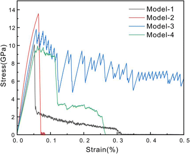
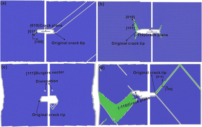
The crack growth of Model-1 on the {001} plane as shown in Fig. 3(a). The stress–strain curve of Model-1 during the crack growth process is shown in Fig. 2. Before the yield point is reached, the stress–strain curves show a linear relationship, and elastic deformation occurs in the model. The model reaches the yield point when the strain is 5.17%, and the stress suddenly drops after reaching the maximum. At this time, a plastic zone appears at the crack tip, as shown in Fig. 4(b). The region with the highest stress concentration at the crack tip transforms to FCC structure when Model-1 reaches yield stress. Cells in the catalytic cracking region are shown in Fig. 3(a). For the initially arranged BCC, the out-of-plane vector is [101], and for the FCC region, the out-of-plane vector is [001]. The CNA showed that FCC structure appeared at the crack tip, and the angle from the crack plane was about 35.3°. A rapid twin transition occurs in the plastic zone when the strain is 5.49%, as shown in Fig. 4(c). Twinning occurs in the (121) plane, which is consistent with the expected twin/slip plane of BCC. The cracks propagate along the twin boundary, while the twin layer undergoes expansion as the strain increases. Therefore, the rapid transition and continuous expansion of twins are the main reasons for the crack propagation mode. The crack breaks along the boundary of the model when the strain is 31.4%, as shown in Fig. 4(d). The results show that the crack growth of Model-1 is brittle cleavage, which is determined by the twinning mode under this orientation. | ||
| Fig. 4 Crack propagation process of Model-1. The color of the atoms is made up of CNA, where blue is the BCC atom, green is the FCC atom, and white is the atom of unknown structure. | ||
Model-2 crack growth was observed in the {011} plane as shown in Fig. 3(b). The elastic stage of the stress–strain curve of crack growth in Model-2 is similar to that of Model-1, but the stress rapidly decreases to zero after yielding, as shown in Fig. 2. The microscopic evolution process of crack growth is shown in Fig. 5. Before and during the crack extension, there appeared FCC regions nearly perpendicular to the crack surface, which was caused by the stress relaxation at the crack tip. The FCC zone first appears when the pre-yield strain is 4.99%, as shown in Fig. 5(a). The plastic zone of the crack tip increases when the strain is 6.41%. The crack tip expands rapidly, and the stress–strain curve decreases rapidly when the strain is 6.99%, as shown in Fig. 5(c). The model breaks along the cleavage of plane (1![[1 with combining macron]](https://www.rsc.org/images/entities/char_0031_0304.gif) 0) as the loading continues when the strain is 7.49% as shown in Fig. 5(d). The results show that Model-2 is characterized by brittle cleavage without dislocation emission and twin formation during crack propagation.
0) as the loading continues when the strain is 7.49% as shown in Fig. 5(d). The results show that Model-2 is characterized by brittle cleavage without dislocation emission and twin formation during crack propagation.
 | ||
| Fig. 5 Crack growth in Model-2. The color of the atom is made up of CNA, where blue is BCC, green is FCC, and white is an unknown structure. | ||
Model-3 crack growth is observed on the {001} plane as shown in Fig. 3(c). The stress of Model-3 crack propagation does not suddenly decrease after yield but gradually decreases during twists and turns, as shown in Fig. 2. The characteristics of the stress–strain curves show that the crack propagation mode in this orientation is ductile. The orientation is associated with the {112} 〈111〉 orientation, known as the hard or anti-twin orientation. Cracks at the tip emit a 1/2〈111〉 edge dislocation and move along the {112} plane when the yield strain is 9.49%, as shown in Fig. 6(c). The dislocation is continuously annihilated and formed during the progression of plastic deformation, corresponding to the observed bending trend in the stress–strain curve. The crack tip begins to passivate when the strain is 11.9%, as shown in Fig. 6(d). Dislocation [100] appears directly below the crack, accompanied by crack propagation in the Y direction when the strain is 20.49%, as shown in Fig. 6(c). The continuous formation and annihilation of the dislocation away from the crack tip corresponds to the large fluctuation of the stress–strain curve as the loading continues. Thus, the crack tip passivates in the X direction but expands in the Y direction, as shown in Fig. 6(h).
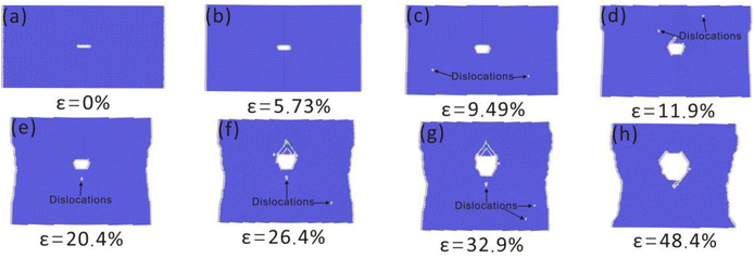 | ||
| Fig. 6 Crack growth in Model-3. The color of the atom is due to CNA, where blue is BCC, green is FCC, and white is an unknown structure. | ||
Model-4 crack growth is observed on the {010} plane as shown in Fig. 3(d). In the crack propagation of Model-4, two obvious plastic platforms appear after yielding, and the link between the two plastic platforms is a sudden drop in stress, as shown in Fig. 2. The crack growth process of Model-4 is shown in Fig. 7, where a plastic zone appears in the 45° plane of the crack tip, that is, the {011} plane. Due to the gradual formation of the plastic deformation region, the propagation of the crack tip in the X direction is inhibited, corresponding to the yield step of the stress–strain curve. As plastic deformation progresses, partial dislocations occur at the crack tip, which refers to the initial parallel displacement of two rows of atoms. Subsequently, a plastic zone with a face-centered cubic (FCC) structure forms ahead of the crack tip. When the strain is 6.49% (Fig. 7(c)), the plastic zone penetrates the model and gradually expands. Then the right side of the crack tip expands rapidly along the plastic zone, corresponding to the stress drop phase in the stress–strain curve, as shown in Fig. 7(d) and (e). The crack propagation on the left side of the crack tip is the same as that on the right side. The plastic region first increases and then expands rapidly, corresponding to the plastic plateau of the stress–strain curve and the second decline. At this orientation, a 45° slip band appears at the crack tip. The length and width of the slip band begin to increase with the increase of strain. The appearance of slip bands is beneficial because it reduces the stress concentration phenomenon at the crack tip, thus delaying and hindering crack propagation. Meanwhile, it is also the most important deformation mechanism in the process of crack propagation.
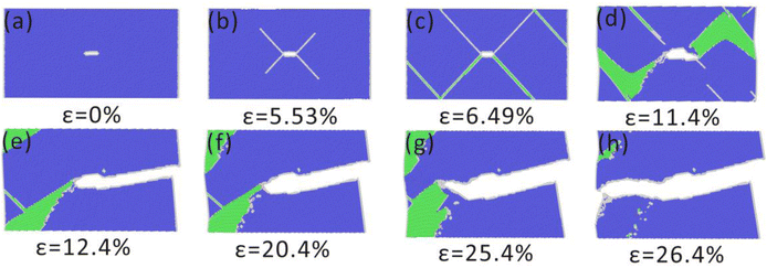 | ||
| Fig. 7 Crack growth in Model-4. The color of the atom is due to CNA, where blue is BCC, green is FCC, and white is an unknown structure. | ||
It can be seen that brittle growth occurs in Model-1 and Model-2 by analyzing the process of crack growth and the stress–strain curves of the four basic orientation models. Model-2 cleavage fracture shows complete brittleness. Model-4 underwent a relatively short process of plastic deformation due to the emergence of slip bands, and then brittle fracture. Model-3 showed strong plasticity due to the continuous appearance and disappearance of dislocations in the stretching process and finally did not break. Next, four single crystal models with different orientations were combined in pairs to compare the crack growth phenomena of the combined model and the single orientation model and to study the synergistic effect of different orientations on the crack growth mechanism.
3.2 Crack propagation behavior of the combined model
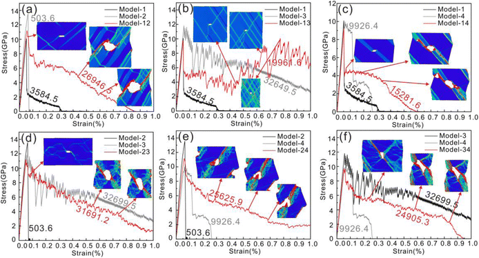
The stress–strain curves of six models are shown in Fig. 8. The plastic work of each model during crack propagation is obtained by integrating the curves. The yield stress of Model-12, Model-24 and Model-34 is between two separate models, and the yield stress of Model-13, Model-14 and Model-23 is lower than that of two separate models. Model-12, Model-14 and Model-34 finally break. Model-23 and Model-24 have a fracture tendency. Model-13 did not break.It can be seen from the calculated plastic work that the toughness of Model-23 is the strongest and that of Model-14 is the weakest among the six combined models. Model-1 exhibits complete brittleness, Model-2 and Model-4 exhibit low toughness, and Model-3 exhibits strong toughness when expanded alone. The toughness of the combined model is 6.48 and 1.13 times higher than that of the single model when the brittle model and the less ductile model are combined, respectively. Both the right and left sides of the crack tip of Model-12 and Model-14 form stress concentration regions throughout the model as shown by the stress distribution diagram in the illustration. The crack tip continued to expand along the stress concentration area, and a fracture occurred. The fracture time of Model-14 is earlier than that of Model-12, because the formation of a hole in front of the crack tip of Model-14 accelerates crack propagation. Model-24 is a combination of two less ductile models, and the toughness is improved by 2.45 times. Stress concentrations also formed on both sides of the model-24 crack, but only the left side was eventually pulled.
The stress–strain response of Model-13 changes from fluctuating downward to rising when the brittleness model is combined with the toughness model.
However, by comparing the plastic work of Model-13 and Model-3 as shown in Fig. 7, it can be obtained that the toughness of the combined model is 0.55 times that of Model-3. The crack growth appears to be dominated by brittle orientation in the early stage and ductile regions in the late stage. The stress distribution diagram of model-13 shows that new stress concentration regions are constantly generated at the crack tip, and the stress concentration does not gradually deepen along a certain region.
The stress–strain trend of Model-23 and Model-34 is similar to that of Model-3, which is 0.95 and 0.58 times lower than that of model-3, respectively. It can be seen from the stress distribution diagram that shear bands are also formed on the left and right sides of the crack in Model-23 and Model-34 during the expansion process. The fracture time of Model-34 is earlier than that of Model-23. This is because the direction of the crack tip changes and the direction of stress concentration also changes during the process of crack propagation, which leads to the slowing down of the crack propagation speed.
The stress value of Model-12 firstly exceeds the yield stress of Model-1 at the elastic stage and then suddenly drops below the yield stress of Model-2. In the elastic phase, the crack propagation process of Model-1 is similar to that of single crack propagation, and the crack opening becomes larger gradually. The crack tip of Model-2 also appears to have a plastic region perpendicular to the crack plane, but this region disappears rapidly. The fault region of part of the crack tip of Model-1 is significantly larger than that of the single expansion, and the fluctuation of the stress–strain curve is accompanied by the annihilation and emission of the dislocation, as shown in Fig. 9(a). The fault region turns into a twin when the strain is 8%. The crack tip does not form stress concentration along the twin plane, but continuously twinning leads to the change of crack direction and passivation, as shown in Fig. 9(b). A hole is formed in front of the crack tip on the right side, and the nucleation of the hole indicates the passivation of crack tip expansion when the strain is 30%, as shown in Fig. 9(c). The combination of crack tip and hole accelerated the crack propagation, and the crack opening displacement gradually increased. Part of Model-1 is pulled off when the strain is 85.5%, as shown in Fig. 9(d).
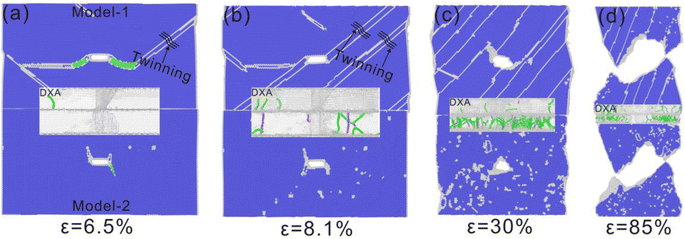 | ||
| Fig. 9 Crack propagation in Model-12. The color of the atom is due to CNA, where blue is BCC, green is FCC, and white is an unknown structure, with dislocation analysis in the middle. | ||
No cleavage fracture occurs in Model-2 due to the lack of peak stress. The crack tip continuously emits dislocations as the strain increases. The propagation of cracks is impeded and passivation occurs. Shear bands gradually form in the plastic region due to the continuous emission of dislocation at the crack tip. The crack tip expands along the shear band direction as the loading continues. Part of Model-2 is pulled off at the same time as Model-1.
It is worth noting that Model-1 and Model-2 both exhibit brittleness characteristics when crack growth is isolated, while the combined Model-12 exhibits ductility characteristics. At the same time, the crack propagation path of Model-12 is almost the same as in Model-1 and Model-2. This shows that the crack propagation process of the combined Model-12 is controlled by the synergistic orientation of the two crystals. The Model 1 part is sufficient to twinning under the action of stress, but the Model 2 part cannot shear fracture along the twin plane due to the limitation of orientation. Therefore, twin-regulated plastic deformation occurs at many places in Model-1, resulting in crack propagation that requires breaking through the barrier of the twin layer. The yield stress of combination Model-12 does not reach the critical value for crack propagation in part Model-2, and cleavage fracture cannot occur. The twining and crack deflection of Model-1 promote the plastic deformation and crack propagation of Model-2, resulting in frequent dislocation movement in part of Model-2. Therefore, the crack growth mode of the combined Model-12 is controlled by Model-1 and Model-2, and the brittle cleavage characteristic changes to the toughness characteristic.
The stress value of Model-13 approaches the yield stress of Model-1 at the elastic stage and then drops suddenly at the yield stress lower than Model-1. The angle of the FCC (plastic) region changes in the crack propagation process of Model-1 in the elastic stage, and the crack opening becomes larger gradually. The crack opening of Model-3 also gradually increased, but the crack did not expand. Part of the crack tip of Model-1 emits dislocations to the surface, and the fault region of the crack tip is obviously smaller than that when the crack tip is extended alone, and twins are also formed, as shown in Fig. 10(a). The fault region is converted into twins, as shown in Fig. 10(b). The twin layer expands continuously as the stretching process progresses. However, the crack tip does not form stress concentration along the twin plane but continuously changes direction and passivates. The twin completely no longer dominates the crack propagation, which is very different from Model-1 when it expands alone. The twin layer disappears, the dislocation along the twin layer and the grain boundary also disappears, and the crack remains in a passivated state when the strain is 45.9%, as shown in Fig. 10(c). The toughness of Model-13 was enhanced after the twin disappeared in Model-1. The crack tip continuously emits dislocations towards the surface as the stretching progresses. At the same time, the model is constantly necked due to its strong plasticity. The plasticity of the combined Model-13 is between Model-1 and Model-3, the crack eventually spreads in the X direction, and the combined Model-13 is not pulled at last.
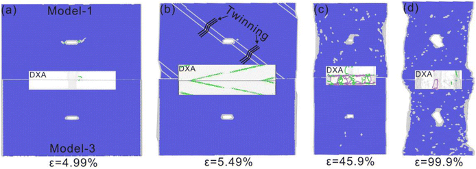 | ||
| Fig. 10 Crack propagation in Model-13. The color of the atom is due to CNA, where blue is BCC, green is FCC, and white is an unknown structure, with dislocation analysis in the middle. | ||
The ductility characteristics of combined Model-13 are between Model-1 and Model-3, but the toughness characteristics are enhanced during crack propagation. Although the peak stress of Model-13 does not reach the peak stress of Model-1, it is sufficient to twinning under the action of this stress. However, part of Model-3 cannot shear fracture along the twin plane due to the limitation, and shows strong plasticity after the twin disappears.
The elastic behavior of Model-14 is similar to that of Model-4, followed by a sudden decline at a yield stress lower than Model-4. A small number of FCC (plastic) regions appeared in Model-1 and Model-4 of the elastic stage, and the crack opening gradually increased. Some crack tips of Model-1 were twinning, as shown in Fig. 11(a). At this time, stress concentration is formed along the twin plane of the crack tip, and the crack expands with the expansion of the twin layer. A hole is formed above the crack tip on the left side when the strain is 20.3%. A hole is formed on the right side of the crack tip when the strain is 34.9%, and the nucleation of the hole indicates the passivation of crack tip expansion, as shown in Fig. 11(b) and (c). The combination of crack tip and hole accelerated the crack propagation, and the crack opening displacement gradually increased. Part of Model-1 is pulled off when the strain is 62.5%, as shown in Fig. 11(d).
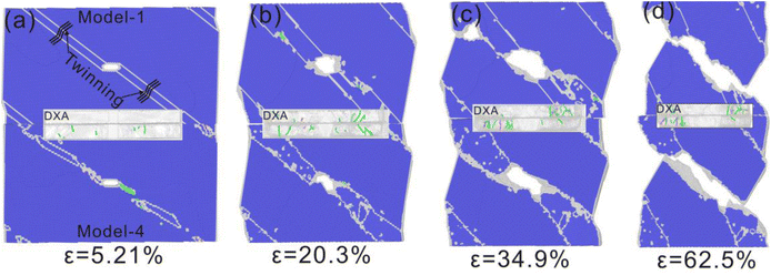 | ||
| Fig. 11 Crack propagation in Model-14. The color of the atom is due to CNA, where blue is BCC, green is FCC, and white is an unknown structure, with dislocation analysis in the middle. | ||
Due to the lack of peak stress, only a small part of the fault region appears in Model-4 instead of a large surface fault driving crack propagation as when the model is expanded alone. The crack tip emits dislocations continuously as the loading continues, and the crack expands along the direction of the dislocation emission. As the crack tip emits dislocations in a fixed direction, the plastic region gradually forms a slip band. Part of Model-4 is pulled apart along the slip band when the strain is 62.5%. Model-4 is partially broken at the same time as Model-1.
Both Model-1 and Model-4 exhibit a certain degree of ductility expansion when crack growth is isolated, and the combined Model-14 enhances the ductility characteristics. However, the enhancement effect is weaker than Model-12. The crack growth path of Model-14 is almost the same in Model-1 and Model-4, indicating that the crack growth process is controlled by the synergistic orientation of the two crystals. The part of Model-1 is sufficient to twinning under the action of stress, and the cracks continue to expand along the twin plane. It should be noted that only single-layer twins appear in Model-14, while multi-layer twins are formed in Model-12. Therefore, the single-layer twin region is conducive to stress concentration and shear band formation while promoting the formation of slip band and crack propagation in Model-4.
The stress value of Model-23 approaches the yield stress of Model-3 in the elastic stage and then fluctuates at a lower yield stress than Model-3. In the elastic phase of Model-2, a plastic region perpendicular to the crack plane appears at the crack tip and disappears rapidly, and the crack opening becomes larger gradually. The crack propagation in Model-3 is the same as that in separate propagation. The plastic region of the crack tip of Model-2 is significantly smaller than that of the crack tip of Model-2 alone. The fluctuation of the stress–strain curve is accompanied by the annihilation and emission of the partial dislocation of Model-2, as shown in Fig. 12(a). Due to the lack of peak stress, no cleavage fracture occurs in Model-2. The crack tip continuously emits dislocation, and the crack propagation is hindered and passivated when the strain is 5.99%, as shown in Fig. 12(b). The plastic region of the crack tip gradually forms a continuous slip band when the strain is 50.9%, as shown in Fig. 12(c). The crack tip expands along the direction of the slip band as the loading continues. The part of Model-2 breaks from the left side when the strain is 94.9%, as shown in Fig. 12(d).
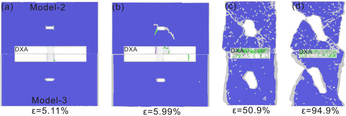 | ||
| Fig. 12 Crack propagation in Model-23. The color of the atom is due to CNA, where blue is BCC, green is FCC, and white is an unknown structure, with dislocation analysis in the middle. | ||
The tip of Model-3 continues to emit dislocations and the cracks continue to passivate after the elastic stage. For the Model-3 part, although it does not reach its peak stress, it shows strong plasticity when it is expanded alone, and the crack opening keeps increasing. The model necked continuously with the continuous loading, and the crack expanded in a direction perpendicular to the crack propagation direction. The left side of the Model-3 part also begins to expand along the shear band direction when the shear band of the Model-2 forms. The Model-2 part and Model-3 part were pulled off at about the same time.
It is worth noting that the ductility characteristics of the combined Model-23 are similar to those of Model-3 when the crack growth is isolated, but the fracture can occur compared with Model-3. Similarly, the crack growth path of Model-23 is almost the same in Model-2 and Model-3, and the crack growth path follows the continuous slip band in Model-2. The formation of the slip band causes the cracks in Model-3 to expand along the slip band. Therefore, the plasticity of composite Model-23 in the early stage of crack growth is similar to that of Model-3, and the fracture can occur in the later stage under the influence of Model-2.
The stress value of Model-24 first exceeds the yield stress of Model-4 in the elastic stage and then fluctuates after a small decrease below the yield stress of Model-2. In the elastic stage, the crack propagation process of Model-2 part is small because the plastic region perpendicular to the crack plane appears and disappears quickly because the yield stress is not reached. The plastic region appears in the Model-4 part as it does when it extended alone. Because the peak stress of Model-2 was not reached, no cleavage fracture occurred. The direction of the crack tip changes and a dislocation is emitted, and the left tip expands along the direction of dislocation emission when the strain is 6.49%, as shown in Fig. 13(b). The crack tip continuously emits dislocations and gradually forms a continuous slip band when the strain is 49.9%, as shown in Fig. 13(c). As the loading continues, the crack tip expands along the direction of the slip band. The left side of the Model-2 breaks, as shown in Fig. 13(e) when the strain is 64.9%.
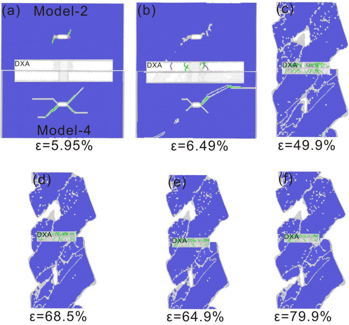 | ||
| Fig. 13 Crack propagation in Model-24. The color of the atom is due to CNA, where blue is BCC, green is FCC, and white is an unknown structure, with dislocation analysis in the middle. | ||
The yield stress of Model-24 exceeds the yield stress of Model-4, so when the yield strain is reached, the crack tip of the Model-4 part produces a plastic region in all directions as if it were extended alone. Due to the influence of Model-2 part, the fault area of Model-4 part does not expand continuously but gradually disappears. As the loading continues, the crack tip begins to emit a dislocation, and the crack begins to spread in the direction in which the dislocation is emitted. Due to the continuous emission of dislocation at the crack tip, shear bands gradually form in the plastic region. As the loading continues, the crack tip expands along the shear band direction. A hole is formed in front of the crack tip on the left side when the strain is 68.5%. The formation of the hole makes the crack sharper and promotes the propagation of the crack, as shown in Fig. 13(d). Part of Model-4 breaks on the left side when the strain is 79.9%, as shown in Fig. 13(f).
It is worth noting that the combined Model-24 shows stronger ductility than the single model. In Model-2 and Model-4, cleavage can occur along the plastic region when the cracks grow separately. However, the direction of the plastic region is inconsistent after the combination of the two, resulting in large plastic deformation of the combined model. The typical characteristic of co-regulated plastic deformation is the formation of a continuous slip zone at the same angle, and the final crack propagation along the slip zone.
The stress value of Model-34 first exceeds the yield stress of Model-4 in the elastic stage and then yields at a lower yield stress than Model-3. In the elastic stage, the crack propagation process of Model-3 is similar to that of single crack propagation, showing strong plasticity and crack opening gradually increasing. Plastic regions appear in the Model-4 part as they do when extended separately.
The part of Model-3 exhibits strong plasticity, and the crack tip continuously emits dislocations to hinder crack propagation. Due to the strong plasticity, the model continues to shrink under tensile strain, and the crack expands along the Y direction. The crack tip on the left side continues to emit dislocations, and a slip band gradually forms in the plastic region when the strain is 43.5%, as shown in Fig. 14(b). As the loading continues, the crack tip expands along the direction of the slip band. Part of Model-3 is pulled apart when the strain of the slip band is 94.9%, as shown in Fig. 14(d).
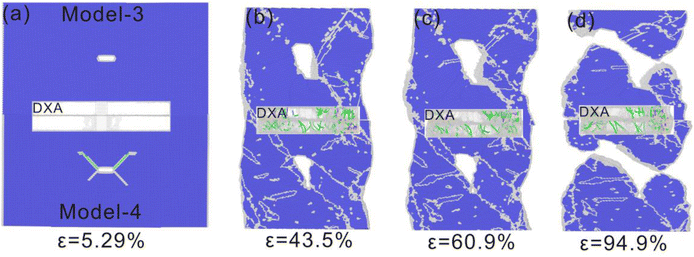 | ||
| Fig. 14 Crack propagation in Model-34. The color of the atom is due to CNA, where blue is BCC, green is FCC, and white is an unknown structure, with dislocation analysis in the middle. | ||
The yield stress of Model-34 exceeds that of Model-4, and the crack tip of Model-4 generates a plastic region in all directions. The Model-4 part is affected by the slip band of the Model-3 part, and the plastic region gradually disappears when the strain is 7.49%. As the loading continues, the crack expands along the y direction due to the necking of the model. The slippage bands of the same angle are gradually generated in the Model-4 part and the Model-3 part. The crack tip extends along the direction of the slip band, and Model-4 partially breaks when the strain is 94.9%.
Model-3 shows strong toughness when extended alone, Model-4 shows weak toughness, and combined Model-34 shows intermediate toughness. This shows that the crack propagation process of the combined Model-34 is controlled by the synergistic orientation of the two crystals. The peak stress of Model-34 reaches the peak stress of Model-4, resulting in a large degree of plastic deformation. However, due to the limitations of Model-3, the crack propagation is hindered. Until the local slip band in Model-4 is produced, the crack tip of the combined model expands along the slip band direction.
The combined model shows the crack propagation behavior through the synergistic action of the two orientations. The synergistic effects of the six combined models are shown as follows Model-1 and Model-2 both show brittleness characteristics when crack growth is isolated, while Model-12 shows ductility characteristics. At the same time, the crack propagation path of Model-12 is almost the same in Model-1 and Model-2. The ductility characteristics of combined Model-13 are between model-1 and Model-3, but the toughness characteristics are enhanced during crack propagation. Although the peak stress of Model-13 does not reach the peak stress of Model-1, it is sufficient to twinning under the action of this stress. However, due to the limitation, part of Model-3 cannot shear fracture along the twin plane, and shows strong plasticity after the twin disappears. Both Model-1 and Model-4 exhibit a certain degree of ductility expansion when crack growth is isolated, and the combined Model-14 enhances the ductility characteristics. The crack growth path of Model-14 is almost the same in Model-1 and Model-4, indicating that the crack growth process is controlled by the synergistic orientation of the two crystals. The ductility of the combined model-23 is similar to that of Model-3 when crack growth is isolated, but the fracture can occur compared with Model-3. Similarly, the crack growth path of Model-23 is almost the same in Model-2 and Model-3, and the crack growth path follows the continuous slip band in Model-2. The crack propagation in Model-3 is also driven by the formation of slip band, which indicates that the crack propagation process is controlled by the two crystal orientations. The ductility of the combined Model-24 is stronger than that of the single model. In Model-2 and Model-4, cleavage can occur along the plastic region when the cracks grow separately. However, the direction of plastic region is inconsistent after the combination of the two, resulting in large plastic deformation of the combined model. The typical characteristic of co-regulated plastic deformation is the formation of a continuous slip zone at the same Angle, and the final crack spreads along the slip zone. The peak stress of Model-34 reaches the peak stress of Model-4, resulting in a large degree of plastic deformation. However, due to the limitation of Model-3, the crack propagation is hindered. Until the local slip band in Model-4 is produced, the crack tip of the combined model expands along the slip band direction. This shows that the crack propagation process of the combined Model-34 is controlled by the synergistic orientation of the two crystals. All the above phenomena indicate that there is a synergistic effect between grains with different orientations.
4. Conclusion
The influence of various crystal orientations on the fracture behavior of BCC-Fe was investigated in this study using the molecular dynamics method, considering both single and combined models. The results indicate that the crack propagation behavior following different combinations of models is significantly influenced by the inherent characteristics and synergistic effects of diverse crystal orientations. The ductile behavior observed in crystal orientations with more pronounced brittle characteristics can be attributed to the influence of synergistic effects. The resilience of the six composite models in order from highest to lowest is Model-23, Model-12, Model-24, Model-34, Model-13, and Model-14. The Model-14 exhibits the lowest toughness among them and is highly susceptible to fracture. After the combination of Model-12 and Model-14, there was a significant increase in toughness, with improvements of 6.48-fold and 1.13-fold respectively. The resilience improvement of Model-13, in contrast, exhibits a relatively modest increase of only 0.55 times.Data availability
Data for this article, including [Potential function] are available at [https://www.ctcms.nist.gov/potentials/system/Fe/#Fe] at [https://doi.org/10.1080/14786430310001613264]. The code for [Lammps] can be found at [https://docs.lammps.org/Commands_all.html]. The version of the code employed for this study is version [LAMMPS (2 Aug 2023)]. The code for [Ovito] can be found at [https://www.ovito.org/docs/current/reference/index.html]. The version of the code employed for this study is version [OVITO 3.10.6].Conflicts of interest
There are no conflicts to declare.Acknowledgements
This study was financially supported by the Funding Supported by National Key R&D Program of China (Grant No. 2022YFC3005002).References
- T. Shinko, D. Halm, G. Benoit and G. Hénaff, Theor. Appl. Fract. Mech., 2021, 112, 102885 CrossRef CAS.
- H. Mughrabi, K. Herz and X. Stark, Int. J. Fract., 1981, 17, 193–220 CrossRef CAS.
- C. V. Cooper and M. E. Fine, Metall. Trans. A, 1985, 16, 641–649 CrossRef.
- F. Yanagimoto, K. Shibanuma, K. Suzuki, T. Matsumoto and S. Aihara, Mater. Des., 2018, 144, 361–373 CrossRef CAS.
- Y. Ogawa, D. Birenis, H. Matsunaga, A. Thøgersen, Ø. Prytz, O. Takakuwa and J. Yamabe, Scr. Mater., 2017, 140, 13–17 CrossRef CAS.
- U. A. Özden, K. P. Mingard, M. Zivcec, A. Bezold and C. Broeckmann, Int. J. Refract. Met. Hard Mater., 2015, 49, 261–267 CrossRef.
- Y. Dewang, M. S. Hora and S. K. Panthi, Mater. Today: Proc., 2015, 2, 1934–1941 CAS.
- N. Mos, J. Dolbow and T. Belytschko, Int. J. Numer. Methods Eng., 1999, 46, 131–150 CrossRef.
- N. Moës, A. Gravouil and T. Belytschko, Int. J. Numer. Methods Eng., 2002, 53, 2549–2568 CrossRef.
- G. V. Stepanov and A. V. Shirokov, Strength Mater., 2010, 42, 426–431 CrossRef.
- L.-h. Ma, Z.-z. Song, K. Zhang, L. Wang, W. Zhou and Q. Zhang, Mater. Res. Express, 2022, 9, 086512 CrossRef CAS.
- I. Ringdalen Vatne, A. Stukowski, C. Thaulow, E. Østby and J. Marian, Mater. Sci. Eng., A, 2013, 560, 306–314 CrossRef CAS.
- J. Nohava, P. Hausild, M. Karlik and P. Bompard, Mater. Charact., 2002, 49, 211–217 CrossRef CAS.
- I. R. Vatne, E. Østby, C. Thaulow and D. Farkas, Mater. Sci. Eng., A, 2011, 528, 5122–5134 CrossRef CAS.
- J. Prahl, A. Machová, A. Spielmannová, M. Karlík, M. Landa, P. Haušild and P. Lejček, Eng. Fract. Mech., 2010, 77, 184–192 CrossRef.
- Y.-F. Guo, Mater. Sci. Eng., A, 2003, 349, 29–35 CrossRef.
- Y. Guo, Y. Wang and D. Zhao, Acta Mater., 2007, 55, 401–407 CrossRef CAS.
- C. H. Ersland, I. R. Vatne and C. Thaulow, Modell. Simul. Mater. Sci. Eng., 2012, 20, 075004 CrossRef.
- S. K. Paul, S. Kumar and S. Tarafder, Bull. Mater. Sci., 2018, 41, 148 CrossRef.
- D. S. Kryzhevich, A. V. Korchuganov and K. P. Zolnikov, Results Phys., 2022, 33, 105163 CrossRef.
- Z. Zhao, Z. Qin and F. Chu, Comput. Mater. Sci., 2020, 172, 109341 CrossRef CAS.
- Z. Zhao, F. Chu and Y. Wei, Mater. Sci. Eng., A, 2021, 809, 140948 CrossRef CAS.
- Z. Zhao, B. Safaei, Y. Wang, F. Chu and Y. Wei, Mater. Des., 2022, 215, 110515 CrossRef CAS.
- Z. Zhao, Y. Wang, B. Safaei, H. Long, F. Chu and Y. Wei, Mater. Today Commun., 2021, 29, 102981 CrossRef CAS.
- A. Kedharnath, A. S. Panwar and R. Kapoor, Comput. Mater. Sci., 2017, 137, 85–99 CrossRef CAS.
- S. Plimpton, J. Comput. Phys., 1995, 117, 1–19 CrossRef CAS.
- L. S. I. Liyanage, S.-G. Kim, J. Houze, S. Kim, M. A. Tschopp, M. I. Baskes and M. F. Horstemeyer, Phys. Rev. B: Condens. Matter Mater. Phys., 2014, 89(9), 094102 CrossRef.
- C. Deng and F. Sansoz, Phys. Rev. B, 2010, 81, 155430 CrossRef.
- J. Sun, L. Fang, A. Ma, J. Jiang, Y. Han, H. Chen and J. Han, Mater. Sci. Eng., A, 2015, 634, 86–90 CrossRef CAS.
- W. C. Swope, H. C. Andersen, P. H. Berens and K. R. Wilson, J. Chem. Phys., 1982, 76, 637–649 CrossRef CAS.
- J. Yu, C. Dong, Q. Zhang, B. Li and R. Liu, Comput. Mater. Sci., 2019, 162, 162–170 CrossRef CAS.
- J. Yu, M. Wang and S. Lin, ACS Nano, 2016, 10, 11044–11057 CrossRef CAS PubMed.
- J. Yu, M. Wang and S. Lin, Comput. Mater. Sci., 2017, 140, 235–243 CrossRef CAS.
- D. Li, F. Wang, Z. Yang and Y. Zhao, Sci. China: Phys., Mech. Astron., 2014, 57, 2177–2187 CrossRef CAS.
- A. Stukowski, Modell. Simul. Mater. Sci. Eng., 2010, 18, 015012 CrossRef.
- F. Shimizu, S. Ogata and J. Li, Mater. Trans., 2007, 48, 2923–2927 CrossRef CAS.
- A. Stukowski, V. V. Bulatov and A. J. M. Arsenlis, Modell. Simul. Mater. Sci. Eng., 2012, 20, 085007 CrossRef.
| This journal is © The Royal Society of Chemistry 2024 |

