 Open Access Article
Growth and atomic oxygen erosion resistance of Al2O3-doped TiO2 thin film formed on polyimide by atomic layer deposition†
Chi Yan a,
Jialin Lia,
Haobo Wang
 a,
Hua Tonga,
Xiaojun Yea,
Kai Wangb,
Xiao Yuana,
Cui Liu*a and
Hongbo Li*a
aSchool of Materials Science and Engineering, East China University of Science and Technology, Shanghai, 200237, China. E-mail: lihongbo@ecust.edu.cn; liucui78@126.com
bCollege of Textiles, Donghua University, Shanghai 201620, China
First published on 31st October 2024
Abstract
Polyimide (PI) coated with atomic layer deposition (ALD) thin films shows promising potential for applications in extreme environments. To achieve a high quality ultrathin ALD coating on the PI surface, Al-doped ALD-TiO2 (ATO) films were deposited on the alkaline hydrothermally activated PI surfaces. The nucleation and growth of ATO films were studied by XPS monitoring and SEM observation. The incorporation of aluminum introduced additional active sites that acted as a seed layer, promoting the adsorption and growth of titanium oxide. This effectively compensated for the defects in the TiO2 film, resulting in the formation of a continuously growing conformal film on the PI surface. After 200 ALD cycles, the ATO film deposited on PI exhibits excellent water vapor barrier properties and significant resistance to atomic oxygen (AO) erosion. When exposed to an AO flux of 1.4 × 10²² atom per cm2, the erosion yield of the PI coated with 200 ALD cycles of ATO film was as low as 2.4 × 10⁻²⁶ cm3 per atom, which is two orders less than that of the standard polyimide-ref Kapton® film.
1. Introduction
Spacecraft play a crucial role as carriers during the exploration of outer space. However, they are extremely susceptible to environmental factors in low-Earth orbit.1–3 Among these factors, atomic oxygen (AO) poses significant risks by causing erosion and degradation of spacecraft materials.4–6 Recently, advances in space exploration technology have led to increased requirements for spacecraft surface materials. Polyimide (PI) is a remarkable polymer material that has been widely used in spacecraft materials due to its excellent dielectric properties, heat resistance, mechanical properties, and chemical stability.7–10 However, under the complex radiation environment of low-Earth orbit, the performance of traditional PI film is significantly reduced, and it is easily corroded and damaged by high-altitude particles such as atomic oxygen and ultraviolet. Therefore, higher demands are placed on the barrier properties and atomic oxygen resistance of polyimide.11–15 Modification and functionalization of conventional polyimides are needed to enhance their protective properties.There are various techniques that can be employed to enhance the performance of PI materials. One such method is surface deposition of functional films, which encompasses sol–gel, physical vapor deposition, and chemical vapor deposition. Inorganic coatings are the most prevalent protective coatings, including aluminum oxide, titanium oxide, and silicon oxide.16–19 These functional films are deposited on the surface of polymers such as PI to improve properties and extend service life. Silicone rubber coatings can be prepared by the sol–gel method to protect PI from UV and AO corrosion.2 An aluminum oxide film was prepared on the PI surface by ion exchange method to improve the mechanical properties of PI.16 Tin oxide films were coated on the PI surface by liquid phase deposition, exhibiting good AO resistance.20 A 400 nm silicon oxide coating was coated on the PI surface by plasma polymerization for protection.18 A pp-HMDSO film was deposited on the Kapton surface by PECVD method to form an AO/UV protective coating.21 While these coatings effectively improve AO resistance, their deposition processes are often complex and require greater thicknesses to function. The increase in thickness can lead to film cracking and failure. Atomic layer deposition (ALD) is a novel film deposition method. Due to its high film density, it is suitable for different basic applications and widely used in semiconductor passivation layer, sealing coating, and corrosion resistance research.22–24 Moreover, ALD can be performed at a lower temperature, which is more suitable for thin film deposition on polymer surfaces.25
However, for inert polymer substrates such as PI, the lack of active groups on the surface will hinder the nucleation and growth of ALD films.26 Therefore, it is necessary to apply an appropriate activation treatment to the substrate surface, promoting the growth of ALD films without affecting the inherent properties of the substrate. Alkaline hydrothermal treatment of PI enables the rapid formation of a hydrophilic surface, facilitating the nucleation and growth of ALD films and improving film density. Furthermore, in certain applications with stringent performance requirements, single-layer ALD films are no longer sufficient. Our previous work has demonstrated that nanometer-scale ALD-TiO2 monolayers can effectively prevent AO erosion.27 However, the nucleation and growth of TiO2 are affected by substrate activity, resulting in slow growth. These deficiencies can be improved by depositing nano-laminated films. J. Meyer et al. studied ALD Al2O3/ZrO2 nanolaminate to form a high-quality water vapor shielding layer.28 Gyeong-Beom Lee deposited Al2O3-doped ZnO (AZO) thin films on PI by ALD. The incorporation of aluminum produced good mechanical properties for the original film.29 Therefore, the ALD nano-laminated films will also have good applications in various fields.
This study introduced the aluminum-doped layer to enhance the performance of ALD-TiO2. The primary focus was on the nucleation and growth of the deposited aluminum-doped titania (ATO) thin films on alkali-activated PI substrates. By incorporating Al2O3 during the deposition of TiO2, additional surface active sites were provided, which further compensated for the defects of the TiO2 film and accelerated the formation of a continuously growing conformal film on the PI surface. The formed ATO film exhibited excellent water vapor barrier properties, further confirming the compactness of the film. Through the ground atomic oxygen simulation test, the formed 200 ALD cycles ATO film has a good atomic oxygen protection effect.
2. Experiment
2.1 Materials and reagents
A commercial polyimide (PI) substrate with a thickness of 150 μm, an initial water vapor transmission rate of 3.68 g m−2 d−1, and a water contact angle of 76° was used. All relevant reagents were purchased from Shanghai Boer Chemical Reagent Ltd., including ethyl alcohol, NaOH. Titanium tetrachloride (TiCl4, 99.9999%, APK GAS), trimethylaluminum (TMA, 99.9999%, APK GAS), deionized water, and argon (Ar, 99.999%) are used as titanium precursor, aluminum precursor, oxidants, and carrier gas for the ALD processes, respectively. All analytical grade chemicals were used without additional purification.2.2 PI surface treatment
The PI films were cut to the appropriate size and sequentially immersed in deionized water and ethanol for ultrasonic cleaning, followed by drying overnight in an oven at 70 °C. Alkali-activated treatment was performed under mild conditions (0.2% NaOH at 60 °C for 5 min) to increase hydrophilicity, ensuring effective ALD modification. The samples were subsequently rinsed at least three times with deionized water and dried with high purity nitrogen (N2, 99.999%).2.3 ALD-Al2O3/TiO2 nano-laminate deposition
Thin films of titanium oxide and aluminum oxide were deposited on activated polyimide using the Optorun ALD system (Optorun Semiconductor System Corporation). The system was operated under a continuous flow of argon carrier gas. Precursors were pulsed using a vapor draw system from the stainless steel precursor cylinders. For the deposition of titanium oxide, an ALD cycle was as follows: (A1) TiCl4 pulses for 100 ms, argon purge for 20 s; (B1) H2O pulses for 50 ms, argon purge for 20 s. For aluminum oxide, one ALD cycle consists of a 50 ms TMA pulse, followed by an argon purge for 20 s (A2), a H2O pulse for 50 ms and another 20 s argon purge (B2). The following ALD cycles were referred to as “XAB,” where X is the ALD cycle number. The deposition temperature was set at 100 °C to prevent polymer matrix expansion and reduce precursor infiltration.30 This ensured a faster growth rate for the deposition of an amorphous titanium oxide film.31The ALD supercycle technique was used to grow the ATO film. The chamber temperature and pressure environment remained unchanged. In the 10 cycle ALD coating deposition, 2 cycles of Al2O3 were pre-deposited, followed by 8 cycles of ALD-TiO2. This complete sequence is referred to as one supercycle, and then ATO thin films were deposited in this order. ATO thin films with 20, 50, 100, and 200 cycles were deposited on the activated PI surface to study their nucleation and growth.
2.4 Characterization
We used a water contact angle tester (WCA, JC2000D1, POWER) for hydrophilicity characterization. The film structure was measured by a Fourier transformed infrared spectrometer (FTIR-Nicolet is50) using an attenuated total reflectance (ATR) accessory. Thermogravimetric analysis was used to test the thermal stability of PI (TG209F1, NETZSCH). The surface compositions and chemical states of elements were characterized by X-ray photoelectron spectroscopy (XPS, ESCALAB 250Xi, Thermo Fisher). Field-emission scanning electron microscopy (FESEM; GeminiSEM 300, Zeiss) was used to observe the surface morphologies (each specimen surface was sputtered with an ultrathin Au layer for better conductivity). To detect the elemental compositions and relative contents, an Xplore spectrometer (Oxford Instruments) was attached to the FESEM equipment in order to perform energy-dispersive spectrometry (EDS). The 3D morphology and surface roughness of the samples were measured using a laser scanning confocal microscope (VK-X100K, Keyence). During ALD film deposition, 4 inch silicon wafers were used as thickness reference samples, and the growth thickness of the ALD film on the silicon surface was measured by an ellipsometer (J. A. Woollam Co. M-2000). In addition, we employed a water vapor transmission rate test system (WVTR, PERME W3/330, Labthink) to measure the water vapor blocking performance. The water vapor transmission rate tests were operated at 38 °C with 90% relative humidity.2.5 Atomic oxygen radiation test
The AO irradiation experiment was conducted using the coaxial ground simulation device at the Shanghai Institute of Space Power Sources to test the film's resistance to AO irradiation in a space environment. The details of the operation structure were given in the previous literature.27 An electron cyclotron resonance (ECR) microwave power source was used to generate oxygen plasma, which is formed into a beam under the influence of an electromagnetic field. The plasma beam is accelerated by an electric field produced by a negatively biased metal plate. Upon acceleration, the plasma beam collides with the metal plate, forming a neutral AO beam with kinetic impact energy, which subsequently interacts with the test samples.32 The average energy of the AO produced by this system was 5 eV, and the flux of AO was determined to be 1.5 × 10¹⁶ AO per cm2 per s. In the present study, the sample was irradiated for a period of 270 h. The samples were dried at 100 °C for 8 h before the atomic oxygen test. Atomic oxygen fluxes and cumulative fluxes are calculated according to the mass loss of commercial standard Kapton samples by the following formula:33in that equation, F = total AO fluence, atoms per cm2; Δmk = mass loss of PI, g; Ak = exposure area of PI, cm2; ρk = density of PI, 1.42 g cm−2; and Ek = erosion yield of Kapton H, 3.0 × 10⁻²⁴ cm3 per atom.
3. Results and discussion
3.1 Alkali activation of polyimide
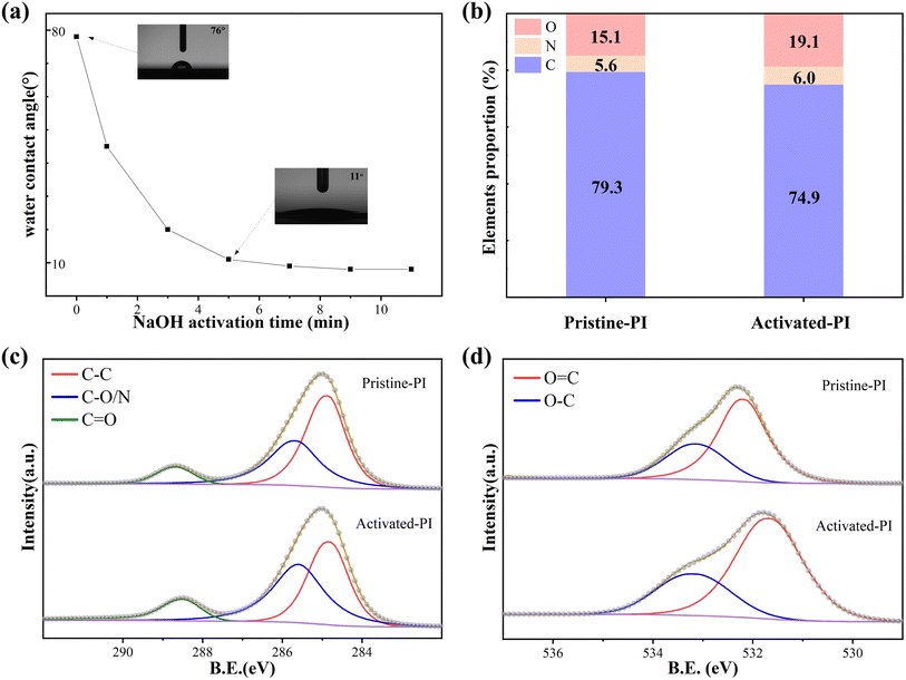
The polyimide surface was activated before ALD film deposition. As shown in Fig. 1a, with the increase of NaOH hydrothermal treatment time, the water contact angle of PI gradually decreased to less than 10 degrees. Excessive NaOH activation time may lead to PI surface damage. The PI surface remained undamaged and showed good hydrophilicity after a 5 minute alkaline heat treatment, with some improvement in roughness (Fig. S1 in ESI†). Following activation treatment, the carbon content dropped from 79.3% to 74.9%, while the oxygen content increased from 15.1% to 19.1%, according to the results of the XPS spectrum analysis (Fig. 1b). The C 1s and O 1s high-resolution spectra of the PI surface before and after activation were analyzed. The C 1s spectrum (Fig. 1c) can be fitted into three peaks at 284.8 eV (C–C), 285.8 eV (C–O/N), and 288.6 eV (C![[double bond, length as m-dash]](https://www.rsc.org/images/entities/char_e001.gif) O), and the O 1s spectrum (Fig. 1d) can be fitted into two peaks at 533.0 eV (O–C) and 532.0 ± 0.2 eV (O
O), and the O 1s spectrum (Fig. 1d) can be fitted into two peaks at 533.0 eV (O–C) and 532.0 ± 0.2 eV (O![[double bond, length as m-dash]](https://www.rsc.org/images/entities/char_e001.gif) C). Table 1 shows the proportions of these groups on the PI surface before and after alkali activation. After activation, the surface of PI exhibited a significant increase in oxygen-containing groups; the content of C–O/N and C
C). Table 1 shows the proportions of these groups on the PI surface before and after alkali activation. After activation, the surface of PI exhibited a significant increase in oxygen-containing groups; the content of C–O/N and C![[double bond, length as m-dash]](https://www.rsc.org/images/entities/char_e001.gif) O functional groups in the composition of C 1s increased significantly. Additionally, there was a corresponding enhancement in the intensity of the O 1s spectral peak. This is mainly attributed to the breaking of amide bonds and the generation of a large number of carboxyl groups after surface treatment. Therefore, abundant oxygen-containing active groups are generated on the surface, which increase the hydrophilicity of the PI surface. Our previous studies have confirmed that these active groups can provide sufficient reaction sites for the subsequent growth of ALD films, thereby facilitating the nucleation and growth of ALD films on the PI surface.27
O functional groups in the composition of C 1s increased significantly. Additionally, there was a corresponding enhancement in the intensity of the O 1s spectral peak. This is mainly attributed to the breaking of amide bonds and the generation of a large number of carboxyl groups after surface treatment. Therefore, abundant oxygen-containing active groups are generated on the surface, which increase the hydrophilicity of the PI surface. Our previous studies have confirmed that these active groups can provide sufficient reaction sites for the subsequent growth of ALD films, thereby facilitating the nucleation and growth of ALD films on the PI surface.27
| Samples | C 1s | O 1s | |||
|---|---|---|---|---|---|
| C–C | C–O/N | C![[double bond, length as m-dash]](https://www.rsc.org/images/entities/char_e001.gif) O O |
O–C | O![[double bond, length as m-dash]](https://www.rsc.org/images/entities/char_e001.gif) C C |
|
| Pristine–PI | 53.34 | 36.67 | 9.99 | 34.47 | 65.53 |
| Activated-PI | 43.23 | 42.80 | 13.97 | 30.38 | 69.62 |
As shown in Fig. S2a,† the FT-IR spectrum shows that the amide characteristic peak of PI remains stable after alkali activation.34 In TGA analysis, the overall thermal gravimetric curves of PI before and after activation are basically the same, and the 95% mass loss temperature does not drop significantly within 420 ± 5 °C (Fig. S2b†). It demonstrates that surface modification has no effect on the overall structure and properties of the substrate while improving the hydrophilicity of the surface.
3.2 ALD-Al2O3/TiO2 nano-laminate deposition
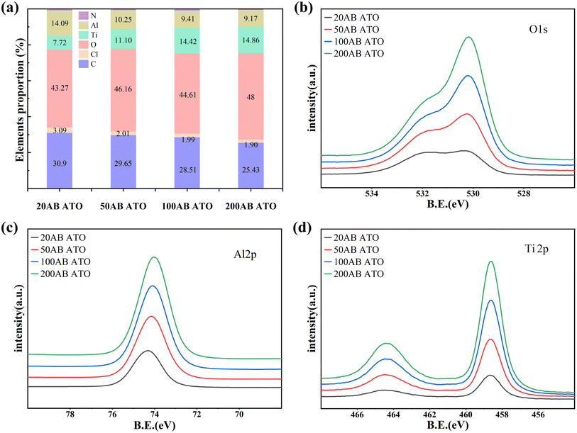
The chemical composition of the ALD coating on the PI surface was analyzed by XPS. Fig. S3† illustrates the elemental distribution on the PI surface after varying cycles of TiO2 deposition. During the initial nucleation and growth of TiO2, after 20 ALD-TiO2 cycles, the C content on the PI surface decreases, while the O content increases, with Ti reaching 6.2%. As the number of deposition cycles increases, the Ti content rises to 21.8% after 200 cycles and stabilizes. The elemental distribution on the PI surface during different ATO deposition cycles is shown in Fig. 2a. Following 20 ALD cycles, compared to the deposition of pure TiO2, the C content on the PI surface decreases further, while the O content increases significantly, and the Ti content rises to 7.72%. These results suggest that the doping of Al2O3 helps to compensate for the defects in TiO2 and provides more active sites to help the nucleation growth of TiO2. The two pre-deposited Al cycles can serve as seed layers, providing more active sites for subsequent TiCl4 adsorption and reaction because of the rapid adsorption growth of TMA on the polymer surface.35 Due to the low doping concentration of Al, the Al deposited in the film is mainly employed to fill the defects of TiO2 without any substitution phenomenon.36 With the increase of deposition cycles, the content of Ti gradually increases, and the corresponding Al element has a certain decrease. The ratio of each element stayed comparatively constant up to 200 cycles of deposition, indicating that the PI surface was uniformly covered by the ATO coating. The high-resolution spectra of O 1s, Al 2p, and Ti 2p in Fig. 2c and d further prove the formation of ATO film. As the number of deposition cycles increases, the intensity of the O 1s peak progressively rises and shifts toward the low binding energy direction, signifying the formation of O–Al/Ti bonds.37 The Al 2p spectrum shifts to lower binding energy while the Ti 2p spectrum moves towards higher binding energy due to a simultaneous decrease in the Al/Ti element ratio.As shown in Fig. 3, the high-resolution spectrum of the 20 cycle ATO film was fitted and analyzed. The C 1s high-resolution spectrum is divided into three single peaks at 284.8 eV, 286 eV, and 288.6 eV, which are respectively attributed to C–C, C–O/N, and C![[double bond, length as m-dash]](https://www.rsc.org/images/entities/char_e001.gif) O. The O 1s spectrum consists of Ti–O–Ti (530 ± 0.1 eV), Ti–OH (531.6 ± 0.1 eV), and O
O. The O 1s spectrum consists of Ti–O–Ti (530 ± 0.1 eV), Ti–OH (531.6 ± 0.1 eV), and O![[double bond, length as m-dash]](https://www.rsc.org/images/entities/char_e001.gif) C/O–C (532.7 eV) peaks.38 The high-resolution spectrum of Ti 2p consists of double peaks of Ti 2p1/2 and Ti 2p3/2 located at 458.5 and 464.3 eV, respectively. After deconvolution, the prominent peaks at 464.3 eV (Ti 2p1/2) and 458.6 eV (Ti 2p3/2) with a separation energy of 5.7 eV are identified as Ti4+ species (TiO2 and Ti–OH), while the peaks at 457.6 and 463.2 eV are assigned to Ti3+ species (Ti2O3).39 The Al 2p spectrum consists of two peaks at 74.3 eV (Al–OH) and 73.8 eV (Al–O).
C/O–C (532.7 eV) peaks.38 The high-resolution spectrum of Ti 2p consists of double peaks of Ti 2p1/2 and Ti 2p3/2 located at 458.5 and 464.3 eV, respectively. After deconvolution, the prominent peaks at 464.3 eV (Ti 2p1/2) and 458.6 eV (Ti 2p3/2) with a separation energy of 5.7 eV are identified as Ti4+ species (TiO2 and Ti–OH), while the peaks at 457.6 and 463.2 eV are assigned to Ti3+ species (Ti2O3).39 The Al 2p spectrum consists of two peaks at 74.3 eV (Al–OH) and 73.8 eV (Al–O).
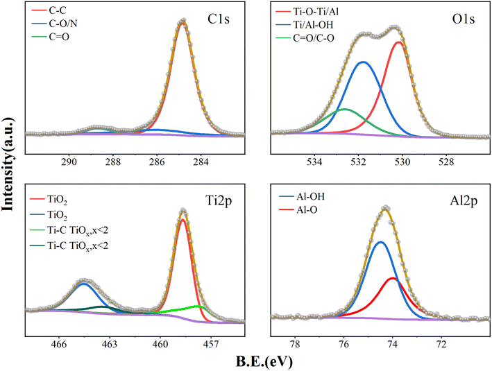 | ||
| Fig. 3 High-resolution peak fitting of surface C 1s, O 1s, Ti 2p and Al 2p XPS spectra of activated-PI after deposition 20 ALD cycles. | ||
Fig. 3 shows the XPS spectra of the PI film surface after 20 ALD cycles. The results of the curve fitting analysis are shown in Table 2. It was observed that in the early stage of ATO film growth, the proportion of Ti/Al–O–Ti has reached 52.72%, Ti/Al–OH accounts for 28.93%, and the remaining fraction was still 18.35% for C–O/C![[double bond, length as m-dash]](https://www.rsc.org/images/entities/char_e001.gif) O. As the ATO deposition thickness increases, the O–C/O
O. As the ATO deposition thickness increases, the O–C/O![[double bond, length as m-dash]](https://www.rsc.org/images/entities/char_e001.gif) C functional group ratio decreases significantly. Following 200 ALD cycles (Fig. 4), the proportion of Ti/Al–O–Ti increased to 79.75%, the proportion of Ti/Al–OH accounted for 15.45%, and the proportion of C–O/C
C functional group ratio decreases significantly. Following 200 ALD cycles (Fig. 4), the proportion of Ti/Al–O–Ti increased to 79.75%, the proportion of Ti/Al–OH accounted for 15.45%, and the proportion of C–O/C![[double bond, length as m-dash]](https://www.rsc.org/images/entities/char_e001.gif) O fell to 4.8%. The measured C–O/C
O fell to 4.8%. The measured C–O/C![[double bond, length as m-dash]](https://www.rsc.org/images/entities/char_e001.gif) O is attributed to C contamination on the sample surface. The presence of Ti/Al–OH is mainly due to thermal ALD, where numerous –OH functional groups are present and some remain unreacted due to steric hindrance. The high-resolution spectral analysis of Ti 2p shows that the film is basically dominated by Ti4+. The proportion of Ti4+ reaches 77.23% after 20 ALD cycles, which further increases to 84.21% after 200 cycles, indicating that tetravalent titanium dioxide still dominates in the formed ATO film. In addition, the high-resolution spectrum of Al 2p shows a rise in Al–O–Al content as the number of cycles increases.
O is attributed to C contamination on the sample surface. The presence of Ti/Al–OH is mainly due to thermal ALD, where numerous –OH functional groups are present and some remain unreacted due to steric hindrance. The high-resolution spectral analysis of Ti 2p shows that the film is basically dominated by Ti4+. The proportion of Ti4+ reaches 77.23% after 20 ALD cycles, which further increases to 84.21% after 200 cycles, indicating that tetravalent titanium dioxide still dominates in the formed ATO film. In addition, the high-resolution spectrum of Al 2p shows a rise in Al–O–Al content as the number of cycles increases.
| Samples | C 1s | O 1s | Ti 2p | Al 2p | ||||||
|---|---|---|---|---|---|---|---|---|---|---|
| C–C | C–O/N | C![[double bond, length as m-dash]](https://www.rsc.org/images/entities/char_e001.gif) O O |
Ti/Al–O–Ti | Ti/Al–OH | O–C/![[double bond, length as m-dash]](https://www.rsc.org/images/entities/char_e001.gif) C C |
Ti4+ | TiOx, x < 2 | Al–OH | Al–O–Al | |
| 20AB PI | 84.12 | 11.41 | 4.47 | 52.72 | 28.93 | 18.35 | 77.23 | 22.77 | 62.63 | 37.37 |
| 200AB PI | 76.18 | 19.31 | 4.51 | 79.75 | 15.45 | 4.8 | 84.21 | 15.79 | 51.21 | 48.79 |
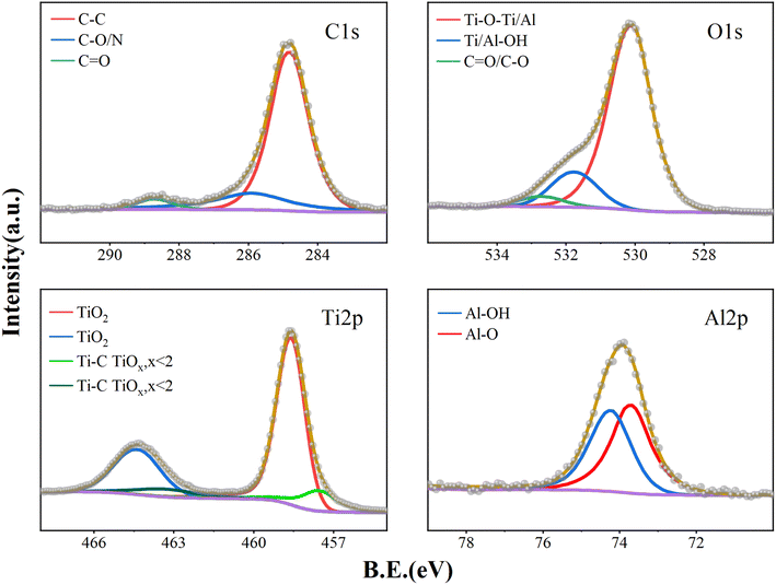 | ||
| Fig. 4 High-resolution peak fitting of surface C 1s, O 1s, Ti 2p and Al 2p XPS spectra of activated-PI after deposition 200 ALD cycles. | ||
The high-resolution spectra of Al and Ti shift with increasing deposition cycles. As shown in Fig. 5, after 200 cycles, the high-resolution spectra of Al and Ti in the ATO thin films showed a significant chemical shift in the peak positions of Al and Ti compared to Al2O3 and TiO2. The binding energy position of Ti 2p increased by about 0.1 eV, while the binding energy of Al 2p decreased by 0.4 eV. These changes in binding energy confirm the existence of Al–O–Ti in ATO coating.37 This is mainly because the electronegativity of Al is higher than that of Ti. In the formed Al–O–Ti structure, the presence of Al affects the electron cloud distribution of O, increases its electron cloud density, and then reduces the electron cloud density around Ti, which is reflected in the change of chemical shift in the XPS test results.
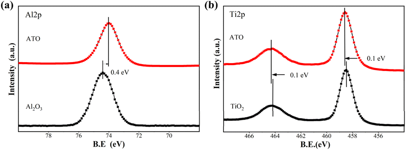 | ||
| Fig. 5 High-resolution XPS spectra of single Al2O3, TiO2 and ATO films on the activated-PI surface after 200 ALD cycles. (a) Al 2p, (b) Ti 2p. | ||
As shown in Fig. S4,† the nucleation and growth process of ALD-TiO2 under different deposition cycles was investigated using FESEM. It was observed that at the initial nucleation stage, numerous clusters form on the PI surface. These clusters only coalesce into a dense film after 200 cycles. The nucleation and growth of the ATO thin film is depicted in Fig. 6. In the early nucleation stage of the 20 ALD cycles, the growth rate of the ATO film formed by adding Al to the TiO2 deposition increased due to the higher adsorption reactivity of TMA than Ti. Therefore, obvious island growth can be observed on the substrate surface, but smaller nuclei have not yet appeared, and larger condensed clusters have been formed at this time (Fig. 6a). After 50 ALD cycles, it can be observed that the ALD film has completely covered the PI surface, but its morphology is relatively loose. As the number of ALD cycles increases, the film density further improves. After 200 ALD cycles, the film surface becomes relatively smooth, forming a denser ATO film (Fig. 6d). The inset of Fig. 6 displays the EDS mapping of Ti and Al elements. The abundance and distribution of the elements scanned by the EDS further demonstrates the level of ATO film deposition on the PI surface with the increasing number of cycles. In the initial stages of nucleation, the weight ratio of Al is greater than that of Ti, indicating that Al is more likely to adsorb and grow on the surface in the early stage. The addition of Al2O3 cycles helps promote the adsorption growth of TiO2. The weight ratio of Ti rises with additional ALD cycles, essentially in line with pure TiO2. This further demonstrates that aluminum doping plays a role in filling the gaps and compensating for film defects, promoting rapid adsorption and deposition of titanium oxide on the surface.
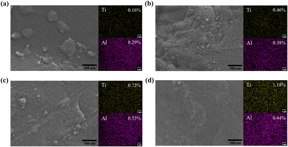 | ||
| Fig. 6 FESEM images and EDS element mapping of PI surface after different ALD cycles: (a) 20 ALD cycles. (b) 50 ALD cycles. (c) 100 ALD cycles. (d) 200 ALD cycles. | ||
3.3 Blocking effect
We measured the water vapor transmission rate of PI coated with ATO film (Table 3). The mechanism of water vapor transmission rate testing has been mentioned in previous literature.40 As shown in Table 3, alkali-activated PI's water vapor transmission rate was 3.68 g m−2 d−1. The WVTR test results are consistent with the growth morphology of the ATO film shown in Fig. 6. After 100 ALD cycles, a uniform ATO film is formed on the PI surface, reducing the WVTR to 0.095 g m−2 d−1. After 200 ALD cycles, the thickness and density of the ATO film further increase, forming an effective shield that extends the water vapor permeation path and reduces the WVTR to 0.005.| Samples | Water vapor transmission rate (g m−2 d−1) | ||
|---|---|---|---|
| 0 cycles | 100 cycles | 200 cycles | |
| TiO2–PI | 3.68 ± 0.095 | 0.532 ± 0.088 | 0.04 ± 0.015 |
| ATO–PI | 0.095 ± 0.035 | 0.005 ± 0.008 | |
These data are significantly improved compared to a single layer of pure TiO2. The continuous and conformal ATO film effectively blocks the permeation of water vapor. Mainly because the incorporation of aluminum promotes the nucleation and growth of titanium oxide, inhibits its crystallization, and reduces defects caused by grain boundaries in the film. It is further indicated that this ATO coating has better water vapor shielding effect and durability compared with single-layer titanium oxide coatings.41
3.4 Atomic oxygen erosion resistance
The pristine–PI and the PI coated with 200 ALD cycles of ATO film were placed in an AO simulation device for AO erosion experiments. The mass loss and erosion rate of the samples after AO erosion are shown in Table 4. In the previous study, the mass loss and the erosion rate of the pristine–PI were 9.40 mg cm−2 and 1.74 × 10⁻²⁴ cm3 per O atom after 72 hours of AO exposure. As the AO irradiation time increased to 270 h, the AO flux reached 1.4 × 10²² atoms per cm2, the pristine–PI was completely eroded and broken, while the ATO-coated PI remained intact with the erosion rate of 2.43 × 10⁻²⁶. The mass loss of 0.45 mg cm−2 may be attributed to the smaller particles of the ATO film being lost at the sample's edge due to AO bombardment. This shows that the ATO coating has a good effect of resisting AO erosion. The Ti–O–Al inorganic structure formed on the surface of the PI substrate possesses high chemical energy and is inert to reactions.42–44 Consequently, ATO films demonstrate enhanced resistance against AO compared to polymer substrates. The dense coating also blocks AO penetration and effectively prevents reaction with the organic substrate.As shown in Fig. 7, the morphology of the sample surface after AO irradiation was analyzed by SEM. It can be observed that significant damage occurred on the surface of the pristine–PI sample, resulting in a coral-like morphology. In contrast, the surface of PI coated with ATO film remained intact after AO irradiation. The EDS spectrum showed that the content of Ti and Al elements on the surface decreased to a certain extent compared with that before irradiation, but was still evenly distributed, indicating that this nanoscale ATO film on the surface can resist erosion from AO and provide excellent protection. The optical 3D morphology further confirmed the protective effect of the ATO film (Fig. S5†). After AO irradiation, numerous grooves formed on the surface of the pristine–PI, causing denudation of its surface structure and a significant increase in arithmetic average roughness (Ra) to 2.363 μm. However, the surface of ATO–PI did not change significantly, and Ra remained unchanged at 0.033 μm. It is evident that after AO erosion, the surface of the ATO-coated PI sample remained smooth and dense, with no cracks or voids observed. The uniform and compact ATO film can effectively retard or even prevent the “undercutting” effects of AO erosion. As shown in Fig. S6,† based on the growth rate of ALD films on silicon wafers, the estimated thickness of the 200 cycle ATO film is approximately 15–20 nm. This nanoscale ultrathin film effectively minimizes the formation of defects such as cracks in the coating. Furthermore, the doping of ALD-Al2O3 helps enhance the mechanical properties of the film, preventing AO diffusion and erosion through defects.4,45
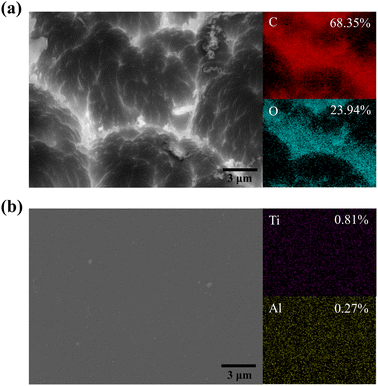 | ||
| Fig. 7 FESEM images and EDS element mapping of PI and 200 cycles ATO film coated PI after AO erosion: (a) PI surface morphology. (b) ATO@PI surface morphology. | ||
As shown in Fig. 8a, FTIR analysis was performed on the sample after AO exposure. Curve I is the FTIR spectrum of the pristine–PI before AO exposure, and several typical polyimide characteristic peaks are clearly visible (imide I to imine IV bands).27 Curves II and III are the FTIR spectra of pristine–PI and ATO–PI after AO exposure. After AO exposure, the transmittance of the pristine–PI increased significantly, and the intensity of these imide bands decreased greatly (curve III), indicating that the erosion of AO leads to the destruction of the polyimide molecular chain and structure.46 On the contrary, the polyimide peak of the infrared spectrum of PI covered with ATO film was clearly visible and did not change significantly, indicating that the polyimide structure was intact and 200 cycles ATO film effectively protects PI from atomic oxygen erosion.
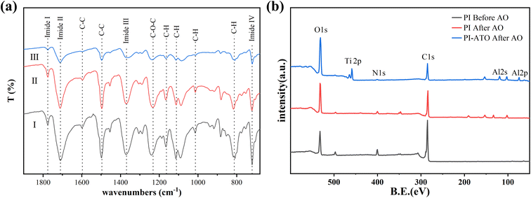 | ||
| Fig. 8 (a) FTIR spectra of (I) PI before AO erosion, (II) 200 cycles ATO–PI after AO erosion, (III) PI after AO erosion. (b) XPS of PI and 200 cycles ATO film coated PI after AO erosion. | ||
XPS spectrum analysis (Fig. 8b) of the sample surface after AO corrosion showed that there was no obvious change in the surface element composition after AO corrosion, indicating that no additional corrosion products were formed, which was consistent with FTIR. The analysis reveals an increase in the O element content and a significant decrease in the C element content of the pristine–PI sample after AO erosion, primarily due to oxidation of surface groups on PI by AO, resulting in the formation of volatile products such as CO2 and CO.18 However, the elemental content of Ti and Al on the surface of ATO–PI after AO corrosion remains present, although there is some reduction. It is shown that the 200 cycle ATO film deposited on the PI surface can effectively resist atomic oxygen attack and provide protection for polyimide.
4. Conclusion
In summary, a nanoscale ATO film was deposited on the surface of PI after alkali activation. By incorporating Al during the deposition of ALD-TiO2, the strong adsorption capacity of TMA in the early growth stage can serve as a seed layer to provide more OH groups as active sites, further promoting the nucleation of ALD-TiO2. The incorporation of Al in the subsequent growth can inhibit the crystallization of TiO2, reduce grain boundary defects, and form a dense and compact ATO film. After 200 ALD cycles, the nanoscale ATO film formed exerted excellent water vapor barrier properties. At the same time, due to the strong antioxidative properties of the Ti–O–Al bond and the high density of the ATO film, a nanometer-thick ATO layer on polyimide can effectively mitigate the undercutting effect of AO erosion, significantly enhancing AO resistance. After the AO erosion experiment, the measured AO erosion yield dropped significantly, equivalent to only 1.4% of the pristine polyimide, showing good application potential in outer space.Data availability
Data are available upon request from the authors.Conflicts of interest
There are no conflicts to declare.Acknowledgements
This research is supported by two sources: the Central Government Guiding Local Project of the Department of Science and Technology of Tibet Autonomous Region [Grant No. XZ202301YD0025C] and the Science and Technology Commission of Shanghai Municipality, China [Grant No. ZJ2022-ZD-010]. The authors extend their gratitude to Shiyanjia Lab (https://www.shiyanjia.com) for providing invaluable assistance with the morphology and XPS analysis. The authors thank the Optorun Semiconductor System Corporation for its support in the atomic layer deposition experiment.References
- D. Wei, F. Zeng and J. Cui, J. Phys. Chem. A, 2024, 128, 378–391 CrossRef CAS PubMed.
- K. Wang, J. Ma, Y. Li, Y. Ding, N. Chen, H. Shao and J. Jiang, Surf. Coat. Technol., 2024, 482, 13072 CrossRef.
- M. Merisalu, L. Aarik, H.-M. Piirsoo, J. Kozlova, A. Tarre, R. Zabels, J. Wessing, A. Brieva and V. Sammelselg, J. Electrochem. Soc., 2022, 169, 071503 CrossRef CAS.
- C. Huang, J. Liu, L. Zhao, N. Hu and Q. Wei, Composites, Part A, 2023, 168, 107459 CrossRef CAS.
- Y. He, A. Suliga, A. Brinkmeyer, M. Schenk and I. Hamerton, Polym. Degrad. Stab., 2019, 166, 108–120 CrossRef CAS.
- R. Lian, X. Lei, S. Xue, Y. Chen and Q. Zhang, Appl. Surf. Sci., 2021, 535, 147654 CrossRef CAS.
- P. Ma, C. Dai, H. Wang, Z. Li, H. Liu, W. Li and C. Yang, Compos. Commun., 2019, 16, 84–93 CrossRef.
- Y. Zhang, B. H. Wu, H. L. Wang, H. Wu, Y. C. An, X. X. Zhi and J. G. Liu, Nanomaterials, 2021, 11, 1886 CrossRef CAS PubMed.
- D.-J. Liaw, K.-L. Wang, Y.-C. Huang, K.-R. Lee, J.-Y. Lai and C.-S. Ha, Prog. Polym. Sci., 2012, 37, 907–974 CrossRef CAS.
- J. A. Spechler, T.-W. Koh, J. T. Herb, B. P. Rand and C. B. Arnold, Adv. Funct. Mater., 2015, 25, 7428–7434 CrossRef.
- P. Tong, Q. Wei, N. Hu and X. Chen, Coatings, 2022, 12, 179 CrossRef CAS.
- X. Wang, Y. Li, Y. Qian, H. Qi, J. Li and J. Sun, Adv. Mater., 2018, e1803854, DOI:10.1002/adma.201803854.
- W. Li, H. Hao, M. He, J. Xing, H. Gao and J. Dong, Surf. Coat. Technol., 2014, 258, 991–995 CrossRef CAS.
- T.-Y. Kim, J.-H. Choi and S.-M. Lee, Surf. Coat. Technol., 2015, 275, 219–223 CrossRef CAS.
- T. Hirvikorpi, R. Laine, M. Vähä-Nissi, V. Kilpi, E. Salo, W.-M. Li, S. Lindfors, J. Vartiainen, E. Kenttä, J. Nikkola, A. Harlin and J. Kostamo, Thin Solid Films, 2014, 550, 164–169 CrossRef CAS.
- D. Jiang, D. Wang, G. Liu and Q. Wei, Coatings, 2019, 9, 624 CrossRef.
- I. Gouzman, O. Girshevitz, E. Grossman, N. Eliaz and C. N. Sukenik, ACS Appl. Mater. Interfaces, 2010, 2, 1835–1843 CrossRef CAS.
- H. Mu, X. Wang, Z. Li, Y. Xie, Y. Gao and H. Liu, Vacuum, 2019, 165, 7–11 CrossRef CAS.
- N. Shimosako, Y. Hara, K. Shimazaki, E. Miyazaki and H. Sakama, Acta Astronaut., 2018, 146, 1–6 CrossRef CAS.
- K. Gotlib-Vainstein, I. Gouzman, O. Girshevitz, A. Bolker, N. Atar, E. Grossman and C. N. Sukenik, ACS Appl. Mater. Interfaces, 2015, 7, 3539–3546 CrossRef CAS PubMed.
- Y. Li, Z. Li, Y. He, H. Wang, K. Zhang, L. Yuan, S. Cao, D. Ma, L. Li, M. Yang, H. Gao, K. Wang, M. Xu and D. Li, ACS Appl. Mater. Interfaces, 2023, 15, 48810–48817 CrossRef CAS.
- T. K. Minton, B. Wu, J. Zhang, N. F. Lindholm, A. I. Abdulagatov, J. O'Patchen, S. M. George and M. D. Groner, ACS Appl. Mater. Interfaces, 2010, 2, 2515–2520 CrossRef CAS.
- K. L. Jarvis and P. J. Evans, Thin Solid Films, 2017, 624, 111–135 CrossRef CAS.
- H. C. Guo, E. Ye, Z. Li, M.-Y. Han and X. J. Loh, Mater. Sci. Eng., C, 2016, 70, 1182–1191 CrossRef.
- S. M. George, Chem. Rev., 2010, 110, 111–131 CrossRef CAS PubMed.
- Z. Zhang, C. Yan, J. Xu, C. Liu, X. Ye, X. Yuan and H. Li, Appl. Surf. Sci., 2022, 598, 153751 CrossRef CAS.
- C. Yan, H. Tong, C. Liu, X. Ye, X. Yuan, J. Xu and H. Li, Nanotechnology, 2024, 35, 265704 CrossRef.
- J. Meyer, H. Schmidt, W. Kowalsky, T. Riedl and A. Kahn, Appl. Phys. Lett., 2010, 96, 243308 CrossRef.
- G.-B. Lee, S. H. Song, M.-W. Lee, Y.-J. Kim and B.-H. Choi, Appl. Surf. Sci., 2021, 535, 147731 CrossRef CAS.
- R. R. Petit, J. Li, B. Van de Voorde, S. Van Vlierberghe, P. F. Smet and C. Detavernier, ACS Appl. Mater. Interfaces, 2021, 13, 46151–46163 CrossRef CAS PubMed.
- J. Aarika and A. Aidla, J. Cryst. Growth, 2000, 220, 531–537 CrossRef.
- Y. Chu, Y. Pan, Y. Gao, X. Qin and H. Liu, Thin Solid Films, 2012, 526, 109–115 CrossRef CAS.
- M. Shu, Z. Li, Y. Man, K. Liu, H. Liu and Y. Gao, Corros. Sci., 2016, 112, 418–425 CrossRef CAS.
- C.-P. Constantin, L. M. Gradinaru, O. Plopa and R.-D. Rusu, Polym. Degrad. Stab., 2022, 202, 110036 CrossRef CAS.
- R. Edy, G. Huang, Y. Zhao, Y. Guo, J. Zhang, Y. Mei and J. Shi, Surf. Coat. Technol., 2017, 329, 149–154 CrossRef CAS.
- Y. Liu, B. Sang, M. A. Hossain, K. Gao, H. Cheng, X. Song, S. Zhong, L. Shi, W. Shen, B. Hoex and Z. Huang, Sol. Energy, 2021, 228, 531–539 CrossRef CAS.
- L. H. Kim, K. Kim, S. Park, Y. J. Jeong, H. Kim, D. S. Chung, S. H. Kim and C. E. Park, ACS Appl. Mater. Interfaces, 2014, 6, 6731–6738 CrossRef CAS PubMed.
- D. Nazarov, I. Ezhov, N. Yudintceva, I. Mitrofanov, M. Shevtsov, A. Rudakova and M. Maximov, Coatings, 2022, 12, 668 CrossRef CAS.
- G. Jnido, G. Ohms and W. Viöl, Coatings, 2019, 9, 441 CrossRef CAS.
- Z. Zhang, C. Yan, C. Liu, X. Ye, X. Yuan and H. Li, Nanotechnology, 2022, 33, 485705 CrossRef CAS PubMed.
- A. I. Abdulagatov, Y. Yan, J. R. Cooper, Y. Zhang, Z. M. Gibbs, A. S. Cavanagh, R. G. Yang, Y. C. Lee and S. M. George, ACS Appl. Mater. Interfaces, 2011, 3, 4593–4601 CrossRef CAS PubMed.
- Y. Zhao, X. Zhao, Z. Shen and X. Zhang, Mater. Today Commun., 2021, 27, 102141 CrossRef CAS.
- H. Niazi, S. Yari, F. Golestani-Fard, M. Shahmiri, W. Wang, A. Alfantazi and R. Bayati, Appl. Surf. Sci., 2015, 353, 1242–1252 CrossRef CAS.
- M. Khosravi, M. R. Toroghinejad, M. R. Vaezi and A. Saidi, J. Mater. Sci.: Mater. Electron., 2020, 31, 7150–7163 CrossRef CAS.
- R. Cooper, H. P. Upadhyaya, T. K. Minton, M. R. Berman, X. Du and S. M. George, Thin Solid Films, 2008, 516, 4036–4039 CrossRef CAS.
- Y. Xie, Y. Gao, X. Qin, H. Liu and J. Yin, Surf. Coat. Technol., 2012, 206, 4384–4388 CrossRef CAS.
Footnote |
| † Electronic supplementary information (ESI) available. See DOI: https://doi.org/10.1039/d4ra06464j |
| This journal is © The Royal Society of Chemistry 2024 |


