Energy-efficient and eco-friendly continuous production of 5-CMF in a UV-ultrasound irradiated catalytic packed bed reactor: heterogeneous kinetics, reactor simulation and LCA analysis†
Sourav
Barman
and
Rajat
Chakraborty
 *
*
Chemical Engineering Department, Jadavpur University, Kolkata-700032, India. E-mail: rajat_chakraborty25@yahoo.com; rajat.chakraborty@jadavpuruniversity.in; Fax: +91 3324146378; Tel: +91 3324572689
First published on 29th September 2023
Abstract
For the first time, a reusable heterogeneous Smopex-101 and TiO2 dual catalytic system was employed successfully for the energy-efficient and eco-friendly synthesis of 5-(chloromethyl) furfural (5-CMF) from soluble starch (SS) under the synergistic photo-thermal effect of UV-ultrasound (US) irradiation. Under mild optimal operating conditions (80 °C, 60 min), the batch (UVUS-BR) and continuous-flow rectangular packed bed reactors (UVUS-RPBR) both resulted in maximum 5-CMF yields of 60.54 mol% and 58.75 mol%, respectively. Significantly, the first-ever heterogeneous surface reaction kinetic model was formulated for the 5-CMF synthesis process, which revealed that the activation energies needed for the different reaction steps involved in the consecutive reaction pathway were 79.04 kJ mol−1 (SS hydrolysis), 61.55 kJ mol−1 (glucose dehydration), and 52.2 kJ mol−1 (5-hydroxymethylfurfural chlorination). RTD analysis and ANSYS fluent simulation study revealed that the utilization of the US energy significantly reduced the non-ideal behavior of UVUS-RPBR (63% reduction in dispersion number). Moreover, the efficacy of UVUS-RPBR in the 5-CMF synthesis process was evaluated, employing the experimentally validated heterogeneous kinetic model parameters. Furthermore, based on comparative LCA analysis, cyclohexane was identified as the most favorable solvent for in situ 5-CMF (purity: 96%) extraction due to its potential environmental advantages over other solvents. The outcomes of the present study can be useful for the scale-up of such reactors for industrial application.
1. Introduction
5-(Chloromethyl) furfural (5-CMF) has recently gained significant attention as a substitute for 5-HMF, primarily because of its higher stability and outstanding hydrophobic properties.1 These unique properties of 5-CMF not only simplify the isolation and purification processes, but also enhance the overall yield of 5-CMF from challenging substrates, such as starch, cellulose, and untreated cellulosic biomass. Furthermore, 5-CMF can be efficiently transformed into various valuable chemicals, such as 2,5-furandicarboxylate, alkoxymethyl furfurals, δ-amino levulinic acid and drop-in biofuels.2,3Several 5-CMF synthesis processes from carbohydrates and cellulosic biomasses in biphasic systems have been developed in the last decades. Mascal et al.4 efficiently prepared 5-CMF (yield >80 mol%) from glucose and cellulose using the HCl/dichloroethane (DCE) biphasic system at 100 °C for 3 h. Onkarappa et al.5 used the aqueous HCl (35%)/DCE biphasic reactor system in the presence of benzyl tributylammonium chloride (BTBAC) as a phase transfer catalyst (PTC), and produced 73 mol% of 5-CMF from sucrose at 90 °C and 3 h. Despite achieving a high yield of 5-CMF, some reported processes suffered from the involvement of corrosive concentrated acids (such as HCl) and toxic chlorinated solvents (DCE), whereas some reported processes suffered from severe process conditions (high temperature (>100 °C); long reaction time); which in turn hindered the overall process sustainability. Recently, a few attempts were made to replace the direct utilization of the corrosive HCl catalyst for the synthesis of 5-CMF in biphasic media.6 For instance, Chen et al.7 reported that the in situ generated HCl from choline chloride and oxalic acid can be used to produce 5-CMF (70 mol%) from glucose using three constituent deep eutectic solvents (choline chloride, AlCl3·6H2O, and oxalic acid) and DCE biphasic medium at 120 °C within 30 min. However, no work has been reported on the 5-CMF production employing a heterogeneous solid catalyst alone to date, even though various types of heterogeneous solid catalysts, including zeolites, sulfonated carbon-based materials, photocatalysts, metal oxides, and acidic ion exchange resins, have been employed for the production of 5-HMF.8–10 Recently, some works on the photocatalytic chlorination of organic substances and photoactivation of organic chlorides have been reported.11 For instance, Ma et al.12 successfully produced methyl chloride using an alkyl chloride salt as the chlorine source under the copper-doped TiO2 photocatalytic system. So, in this study, an attempt was made to produce 5-CMF utilizing a photocatalyst (TiO2) along with a solid acid co-catalyst (Smopex-101) from starch under mild reaction conditions, where choline chloride was used as the chlorine source.
Over the last decade, researchers have studied various halogenated (dichloromethane, dichloroethane, chloroform)13 and non-halogenated solvents (toluene, cyclohexane, methyl isobutyl ketone and cyclopentyl methyl ether)14 as an extracting organic solvent for the isolation of 5-CMF. For instance, Smith et al.14 identified toluene and cyclopentyl methyl ether as promising alternative solvents for halogenated organic solvents in the isolation of 5-CMF. Another work done by Breeden et al.15 investigated both halogenated and non-halogenated extracting solvents on the 5-CMF synthesis process, and revealed that cyclohexane could be a promising alternative as an extracting organic solvent that can be used instead of toxic dichloroethane. Although the non-halogenated solvents have lower toxicity compared to chlorinated solvents, further research is necessary to determine the most promising alternative solvents based on factors such as cost, extraction efficiency of 5-CMF, ease of recyclability, and potential environmental impacts associated with the respective solvents.
Previous literature and our previous studies ascertained that ionizing (X-ray, γ-ray, UV) and non-ionizing electromagnetic waves (visible, infrared, microwave, ultrasonication) could be combined or discretely utilized advantageously for significant augmentation of the reaction rate under milder conditions,16,17 which not only significantly reduced the equipment and operation costs but also decreased the formation of unwanted side products. Although one work reported on the 5-CMF synthesis in a batch reactor under microwave radiation (200 W),15 the combined effect of an ionizing (ultraviolet) and non-ionizing electromagnetic radiation (ultrasound) system on 5-CMF production has not yet been investigated.
Some continuous syntheses of 5-CMF works have also been reported using the corrosive HCl catalyst in a plug flow reactor.18 Kohl et al.19 reported that 85 mol% of 5-CMF yield could be achieved from high fructose corn syrup at 100 °C and 1.5 residence min in a scalable coil-type plug flow reactor. However, no work has reported on the continuous synthesis of 5-CMF in a rectangular packed bed reactor (RPBR) utilizing an ionizing (ultraviolet (UV)) and non-ionizing electromagnetic radiation (ultrasound (US)) system.
Recently, some research studies were reported on the reaction kinetics of the 5-CMF synthesis process in a homogeneous catalytic system. Antonyraj et al.20 presented the first homogeneous kinetic models for the consecutive reaction steps in the 5-CMF synthesis from glucose in a homogeneous catalytic (HCl) system. Another study by Rojahn et al.21 developed homogeneous kinetic models for the consecutive reaction steps in the 5-CMF synthesis from D-fructose. However, no study has yet been reported on the development of heterogeneous kinetic models for the 5-CMF synthesis process under a heterogeneous catalytic (TiO2 and Smopex-101) system.
So, in this work, a combination of heterogeneous reusable photocatalytic and thermo-catalytic systems was employed, where the TiO2 photocatalyst was used along with the Brønsted acidic catalyst Smopex-101 to synthesize 5-CMF from starch in a biphasic system employing choline chloride as the chlorine source. The reaction was intensified employing an ultraviolet (UV) and ultrasound (US) irradiation system in both batch reactor (UVUS-BR) and continuous flow rectangular packed bed reactor (UVUS-RPBR). First, the 5-CMF synthesis process was optimized in a batch reactor using the Taguchi orthogonal design, where selected process factors were optimized to maximize the 5-CMF yield. Afterwards, heterogeneous reaction kinetic models were formulated for the 5-CMF synthesis process under a heterogeneous catalytic system, and kinetic parameters were determined using the experimentally obtained rate data from UVUS-BR under optimized conditions. Finally, the performance of UVUS-RPBR has been assessed for the 5-CMF production process and simulated using the ANSYS FLUENT software. Moreover, an effort was made to identify promising alternative organic solvents based on their extracting efficiency of 5-CMF and associated environmental impacts.
2. Materials and methods
2.1. Materials
Soluble starch (SS) (solubility: 20 g l−1 of water at 25 °C), glucose, and fructose were procured from Merck. Smopex-101 (S-101) fiber (non-porous catalyst with sulfonated acid group; particle diameter: 0.1 mm; length: 4 mm) was collected from Alfa Aesar. Nano TiO2 (mixture of rutile and anatase phase, particle size <100 nm), blue dextran, choline chloride, cyclohexane; dichloroethane (DCE), dichloromethane (DCM), chloroform (CHCl3), methyl isobutyl ketone (MIBK), toluene and glass beads (4 mm) were purchased from Sigma-Aldrich.The purity of the solvents was checked through GC-MS analysis before use in the present study. The procured commercial catalysts (TiO2 and S-101) were oven dried at 80 °C for 1 h before utilization in the reaction.
2.2. 5-CMF synthesis in isothermal batch reactor configuration
The 5-CMF synthesis process from SS was conducted employing an isothermal batch reactor equipped with a UV (8 W; 280–400 nm) and ultrasound (50 W; 20 kHz) (UVUS-BR) energy system. First, a transparent SS solution was prepared by mixing 1 g of SS with 5 ml of water and a measured amount of choline chloride (Table 1) at 80 °C for 10 min. Afterwards, a biphasic solution was prepared by mixing the transparent SS aqueous solution with 10 ml of organic solvent (cyclohexane). Finally, the 5-CMF synthesis process was conducted in UVUS-BR by mixing the biphasic solution with a total of 0.1 g of S-101 and TiO2 solid catalysts at a pre-defined ratio and temperature over a specified time span (Table 1). The reactor temperature was controlled using a PID temperature controller. After reaction, the reaction mix was cooled down to room temperature, and the organic phase and aqueous phase were separated after collecting the catalyst through filtration. Finally, the product (5-CMF) was collected from cyclohexane (Fig. 1) using a vacuum evaporator and analyzed with GC-MS.| Factors | Name | Units | −1 level | 0 level | 1 level |
|---|---|---|---|---|---|
| ∅ T | Temperature | °C | 60 | 70 | 80 |
| ∅ t | Reaction time | min | 30 | 60 | 90 |
| ∅ S101/TiO2 | S-101-to-TiO2 ratio | w/w | 0.5 | 1.5 | 2.5 |
| ∅ ChCl/SS | ChCl-to-SS ratio | w/w | 1 | 3 | 5 |
![[thin space (1/6-em)]](https://www.rsc.org/images/entities/char_2009.gif) :
:![[thin space (1/6-em)]](https://www.rsc.org/images/entities/char_2009.gif) 10, whereas the inlet and source temperature were kept at 250 °C and 280 °C, respectively. The aqueous phase was analyzed by HPLC with both refractive index (RI) and UV detectors (Waters high performance carbohydrate column for glucose and fructose, and C18 column for HMF). An acetonitrile and water mixture (75
10, whereas the inlet and source temperature were kept at 250 °C and 280 °C, respectively. The aqueous phase was analyzed by HPLC with both refractive index (RI) and UV detectors (Waters high performance carbohydrate column for glucose and fructose, and C18 column for HMF). An acetonitrile and water mixture (75![[thin space (1/6-em)]](https://www.rsc.org/images/entities/char_2009.gif) :
:![[thin space (1/6-em)]](https://www.rsc.org/images/entities/char_2009.gif) 25 (V/V)) with a flow rate of 1.4 ml min−1 was utilized as the mobile phase. All of the samples were purified using a syringe filter before the analysis.
25 (V/V)) with a flow rate of 1.4 ml min−1 was utilized as the mobile phase. All of the samples were purified using a syringe filter before the analysis.
![[thin space (1/6-em)]](https://www.rsc.org/images/entities/char_2009.gif) :
:![[thin space (1/6-em)]](https://www.rsc.org/images/entities/char_2009.gif) TiO2 ratio (∅S101/TiO2) and choline chloride-to-SS ratio (∅ChCl/SS) (Table 1). The levels of the selected process factors were chosen based on the one-factorial experimental analysis. The 5-CMF yields (YCMF) were measured as the response value for 9 Taguchi orthogonal designed experimental runs (Table S1†) to evaluate the optimal process conditions for the optimization of the SS conversion to 5-CMF. The detailed 5-CMF yield and SS conversion analysis calculations are summarized in S1.†
TiO2 ratio (∅S101/TiO2) and choline chloride-to-SS ratio (∅ChCl/SS) (Table 1). The levels of the selected process factors were chosen based on the one-factorial experimental analysis. The 5-CMF yields (YCMF) were measured as the response value for 9 Taguchi orthogonal designed experimental runs (Table S1†) to evaluate the optimal process conditions for the optimization of the SS conversion to 5-CMF. The detailed 5-CMF yield and SS conversion analysis calculations are summarized in S1.†
After the optimization study, the optimized 5-CMF synthesis process was carried out with different solvents, namely dichloroethane (DCE), dichloromethane (DCM), chloroform (CHCl3), methyl isobutyl ketone (MIBK), and toluene, to determine the most suitable solvent for the extraction of 5-CMF.
2.3. Plausible reaction mechanism and kinetic model formation
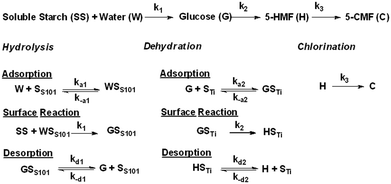
The plausible reaction pathway for the synthesis of 5-CMF from SS in a biphasic system under the S-101/TiO2 catalytic system is shown in Fig. 2. The SS-to-5-CMF conversion reaction was initiated with a hydrolysis step, where SS depolymerized to glucose and oligosaccharides with the aid of the S-101 surface-adsorbed protonated water.22 Afterwards, glucose was isomerized to fructose on the Lewis acidic sites of the TiO2 surface. Subsequently, the produced fructose was dehydrated to 5-HMF on the Brønsted acidic sites of the S-101 catalyst. The chlorination of 5-HMF to 5-CMF took place in the bulk aqueous phase with the help of the photo-oxidized Cl− ion (from ChCl) under UV irradiation.11 Finally, the produced 5-CMF and 5-HMF were transported from the aqueous phase to organic (cyclohexane) phase based on their partition coefficient in organic and aqueous phases.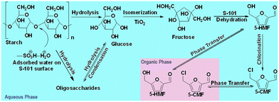 | ||
| Fig. 2 Plausible reaction pathway for the 5-CMF synthesis process under the S-101 and TiO2 catalytic system. | ||
The experimental kinetic study of the 5-CMF synthesis process was performed in the UVUS-BR under optimized conditions. During the experimental kinetic study, glucose, 5-HMF, and 5-CMF were identified as the main products generated within the optimized reaction time (Fig. 7b). Additionally, oligosaccharides and fructose were detected in trace amounts in the product mix. We assumed that the conversion of fructose to 5-HMF through dehydration took place rapidly as it formed.24 Consequently, only a minimal concentration of fructose was detected in the resulting product mixture. Moreover, not more than 2.5 mol% of the other degradation products (such as levulinic acid, formic acid, and levoglucosan) were generated. As a result, they are not considered during the kinetic model formulation. Therefore, the SS-to-5-CMF conversion process under the S-101/TiO2 dual catalytic system was simplified as shown in Fig. 3.
For the SS hydrolysis step, it was assumed that the reactant ‘SS’ (soluble starch) did not get adsorbed on the S-101 surface, and the surface reaction between the adsorbed ‘W’ (water) and ‘SS’ was the rate-limiting step and irreversible. Accordingly, the formulated SS hydrolysis rate (mol gcat.−1 s−1) equation was obtained as follows:
 | (1) |
For the glucose dehydration step, it was assumed that the glucose dehydration reaction on the TiO2 surface was the rate-limiting step and irreversible. So, the glucose generation rate (mol gcat.−1 s−1) was formulated as follows:
 | (2) |
The 5-HMF and 5-CMF generation rate in aqueous phase was evaluated through experimentally determining the partition coefficients of 5-HMF and 5-CMF in the aqueous-organic biphasic system, respectively. When formulating the 5-HMF chlorination reaction rate equation, it is really difficult to measure the in situ generated photo-oxygenated Cl− ion present in the reaction mixture during the reaction. Thus, we consider that the 5-HMF chlorination reaction is a pseudo first-order reaction with respect to 5-HMF. Accordingly, the 5-HMF (eqn (3)), 5-CMF (eqn (4)) generation rates (mol gcat.−1 s−1) in aqueous phase was formulated as follows:
 | (3) |
 | (4) |
 and ∅C
 are the partition coefficients of 5-HMF and 5-CMF in aqueous-organic phase, respectively. CH,Org and CC,Org are the concentrations of 5-HMF and 5-CMF in the organic phase, and CH,Aqu and CC,Aqu are the concentrations of 5-HMF and 5-CMF in the aqueous phase, respectively.
  represents the volume ratio of the organic and aqueous phase, and k3 (1/s) represents the apparent reactant rate constant for the 5-HMF chlorination step.
The activation energies of different reaction steps were calculated according to the Arrhenius equation.
 | (5) |
2.4. 5-CMF synthesis in continuous-flow UVUS-RPBR
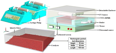
After optimization and kinetic analysis, the 5-CMF synthesis process was also performed in the continuous-flow catalytic rectangular packed bed reactor, i.e., UVUS-RPBR (bed length: 15 cm; width: 5 cm, height: 3 cm) (Fig. 4) under the optimized conditions. The decision to select a rectangular packed bed reactor instead of a cylindrical or tube type reactor was motivated by its improved exposure to both the UV source (positioned on the upper surface of the RPBR) and the US source (positioned beneath the lower surface of the RPBR). Additionally, for a given volume, the rectangular shape reactor inherently offers a smaller surface area compared to cylindrical or tube-type reactors, resulting in lower construction costs for the RPBR in comparison to its counterparts. The reactor bed was filled with the TiO2 and S-101 catalysts at various bed porosities, while maintaining the optimized ∅S101/TiO2 level as in UVUS-BR. In order to address the leaching concern, the TiO2 nanoparticles were initially coated onto glass beads (details given in S3†). Subsequently, the TiO2 coated glass beads were used to fill the reactor bed. Additionally, the reactor's inlet and outlet were covered with a perforated screen [aperture size: 0.1 mm (18 mesh)]. Finally, the UV-A (maximum power: 60 W; 280–400 nm) and US (maximum power: 500 W; 20 kHz) energies were employed synergistically to intensify the conversion process, and the power of the US and UV system was controlled using regulators. Two syringe pumps having infused flow rate ranging between 1–90 ml h−1 were used to precisely control the flow rates of the biphasic SS feed solutions. The reaction mix was collected under steady state after carefully monitoring the different energy systems, and henceforth controlling the reactor temperature. A check valve was also installed to protect the syringe pump against back flow.To understand the influence of the US energy system on the RPBR performance, a comparative study was also performed by conducting the reaction without US (UV-RPBR) at the derived optimized conditions. Notably, in UV-RPBR, the optimized reaction temperature was attained with the help of a conventional heating system (by means of a heating coil; power 500 watt). Moreover, the reusability of the catalysts, viz., TiO2 coated glass beads and S-101 were also studied.
2.5. Life cycle assessment (LCA) analysis of the 5-CMF synthesis process
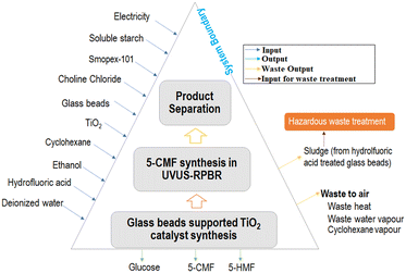
The potential environmental impacts associated with the optimized 5-CMF synthesis process employing different extracting organic solvents was analyzed using OpenLCA 1.9.0 software with Ecoinvent database 3.5. The “ReCiPe Midpoint (H) V1.13” method was used as a life cycle impact assessment (LCIA) methodology to assess the potential environmental impacts.25The system boundary (Fig. 5) for LCA analysis includes the chemical transport, 5-CMF synthesis process, glass beads-supported TiO2 photocatalyst preparation and product separation, wherein the overall analyses were estimated based on 1 kg 5-CMF production under optimized conditions.
The outcomes of the 5-CMF synthesis process were scaled-up according to functional units, and used as a database for the life cycle inventory (LCI) [Tables S2–S4†]. Allocation of the reference product (5-CMF) and by-products (glucose, 5-HMF) were done according to their mass. Moreover, among the total used water, it was assumed that 10% of water was lost as water vapor. All electrical energies used in the entire process were considered to be dissipated as waste heat to air.26 Furthermore, the waste sludge resulting from the hydrofluoric acid treatment of glass beads was assumed to be disposed underground via hazardous waste treatment routes.
3. Results
3.1. Optimization of the 5-CMF synthesis process parameters in UVUS-BR
Analysis of variance analysis (ANOVA) of 5-CMF synthesis process factors in UVUS-BR indicated that the ∅T and ∅ChCl/SS were statistically significant factors (p-value < 0.05) (Table 2). Notably, Table 3 reveals that the process factors with higher Δ values showed a stronger influence on the response factor (YCMF). Accordingly, the order in which the relative significance of the process factors on the response (YCMF) could be arranged as follows: ∅ChCl/SS > ΩT > Ωt > ∅S101/TiO2. Moreover, the highest S/N ratio value (corresponding to highest YCMF) for each process factor was denoted by an asterisk (Table 3), which showed that the optimized process condition for the 5-CMF synthesis process in UVUS-BR was 5 (∅ChCl/SS), 80 °C (ΩT), 60 min (Ωt) and 1.5 (∅S101/TiO2), which results in the highest possible YCMF of 60.54 mol%.| Source | DF | Adj. SS | Adj. MS | F-Value | P-Value |
|---|---|---|---|---|---|
| Regression | 4 | 855.000 | 213.750 | 8.64 | 0.030 |
| ∅ T | 1 | 400.167 | 400.167 | 16.17 | 0.016 |
| ∅ t | 1 | 37.500 | 37.500 | 1.52 | 0.286 |
| ∅ S101/TiO2 | 1 | 0.667 | 0.667 | 0.03 | 0.878 |
| ∅ ChCl/SS | 1 | 416.667 | 416.667 | 16.84 | 0.015 |
| Error | 4 | 99.000 | 24.750 | ||
| Total | 8 | 954.000 |
| Level | ∅ T | ∅ t | ∅ S101/TiO2 | ∅ ChCl/SS |
|---|---|---|---|---|
| −1 | 28.82 | 29.84 | 30.42 | 29.24 |
| 0 | 31.44 | 31.73* | 31.62* | 30.60 |
| +1 | 32.96* | 31.65 | 31.19 | 33.38* |
| Δ | 4.14 | 1.88 | 1.20 | 4.14 |
| Rank | 2 | 3 | 4 | 1 |
3.2. Effect of process parameters on YCMF
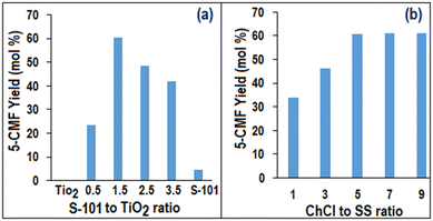
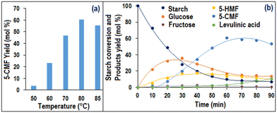
Fig. 6(a) illustrates the effect of ∅S101/TiO2 on YCMF, which indicated that as ∅S101/TiO2 initially increased up to 1.5 wt%, YCMF exhibited an upward trend. However, beyond this point, YCMF started to decrease monotonically as ∅S101/TiO2 continued to increase. Interestingly, no 5-HMF was found when only the TiO2 photocatalyst was used and consequently, no 5-CMF was formed. On the other hand, when only S-101 was used, 33.46 mol% of YHMF was produced and a negligible amount of 5-CMF yield (<5 mol%) was observed. So, from the above observation, it could be concluded that the chlorination of 5-CMF mostly happened in the presence of the TiO2 photocatalyst. Additionally, Fig. 6(b) demonstrates that with increasing ∅ChCl/SS, the YCMF monotonically increased. Notably, it was found that without ChCl, no 5-CMF was produced. This suggested that the Cl− ion of ChCl acts as a chlorine source in the 5-HMF chlorination process, which could be activated through photo-oxidation by the photogenerated hole on the TiO2 surface under UV radiation.11Fig. 7(a) demonstrates that YCMF increased with increasing temperature (∅T) up to 80 °C. After that, YCMF decreased due to the degradation of 5-CMF or 5-HMF to levulinic acid, which could be easily observed from Fig. 7(b). Notably, the maximum achievable temperature in UVUS-BR was limited to 85 °C. As a result, the 5-CMF synthesis process was investigated up to this temperature constraint. On the other hand, the 5-CMF yield monotonically increased with increasing reaction time up to 60 min (Fig. 7(b)). Afterwards, YCMF started to decrease, and an increase in the levulinic acid yield was observed.
3.3. Effect of extracting solvents on the 5-CMF yield
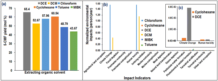
In order to investigate the impact of various extracting solvents on the isolation of 5-CMF, a selection of common halogenated solvents (DCE, DCM, chloroform) and non-halogenated solvents (toluene, cyclohexane, MIBK) was utilized. The findings, presented in Fig. 8(a), indicate that DCE, among the halogenated organic solvents, demonstrated the highest efficiency in isolating 5-CMF (yield: 65.4; purity: 97 ± 0.5%). Conversely, among the non-halogenated solvents, cyclohexane exhibited a promising effect in the isolation of 5-CMF (YCMF: 60.54; purity: 96%).Based on the extracting organic solvents efficacy in terms of the isolated 5-CMF yield from SS and the energy requirement for 1 kg of solvent recycling through vacuum evaporation (Table 4), a comparative life cycle analysis was performed. During LCA analysis, it was assumed that 5% of solvent was loss during recycling (Table S4†). The results indicated that DCM and chloroform exhibited significantly higher environmental impacts concerning climate change and human toxicity indicators (Fig. 8(b)) when compared to other solvents. Notably, in terms of the 5-CMF yield isolation during the synthesis process, DCE and cyclohexane demonstrated higher efficacy. Consequently, their environmental impact contributions were further compared (Fig. 8(c)). The analysis showed that cyclohexane contributed less environmental impacts in terms of climate change compared to DCE. However, both solvents had similar environmental impacts in terms of human toxicity. As a result, cyclohexane was identified as a promising extracting solvent for the 5-CMF synthesis process in future studies. Notably, the price of the solvents is an important factor in selecting a suitable solvent for the 5-CMF extraction process, but proper recycling of the solvent can render the price factor insignificant, despite its initial importance in solvent selection.
| Solvents | Boiling point (K) at 1.01325 bar | Price ($ per ton) | Heat capacity (kJ kg−1 K−1) | Energy required to recycle 1 kg solvent (kJ) |
|---|---|---|---|---|
| DCM | 312.75 | 355.45 | 1.28 | 50.74 |
| DCE | 357.15 | 369.90 | 1.06 | 89.04 |
| Chloroform | 233.15 | 289.80 | 1.02 | 61.27 |
| Toluene | 383.75 | 988.83 | 1.89 | 209.19 |
| Cyclohexane | 353.90 | 921.78 | 1.69 | 136.59 |
| MIBK | 389.15 | 1722.53 | 2.17 | 252.25 |
After selecting cyclohexane as a suitable extracting solvent, 5-CMF yields from different starting monosaccharides (such as fructose, glucose) were also evaluated under optimized conditions. It was observed that a maximum of 81.15 and 68.5 mol% of 5-CMF yield can be achieved form fructose and glucose, respectively.
3.4. Kinetics parameters evaluation for the 5-CMF synthesis process
The calculated Ω values for all reaction steps in the synthesis process of 5-CMF (0.084 for SS hydrolysis, 0.042 for glucose dehydration, and 0.11 for the 5-HMF chlorination step) consistently remain below 0.15. These results indicate that, as per the Mears criterion, the impact of the external mass transfer resistance between reactants and catalyst particles is negligible throughout the various reaction steps involved in producing 5-CMF. Moreover, at the optimized organic–aqueous volume ratio (1.953), the partition coefficient values of 5-HMF and 5-CMF were determined, and the obtained partition coefficients for 5-HMF (∅H) and 5-CMF (∅C) were 0.061 and 485, respectively.The SS-to-5-CMF conversion kinetic data obtained from UVUS-BR at the optimal reaction conditions were fitted in the formulated kinetic models employing MATLAB R2014a (Table 5) at different temperatures. From Table 5, it can be observed that the formulated kinetic models demonstrated close proximity to the experimental data with high R2 adj. (≥0.93) and low RMSE values (≤6.15 × 10⁷). Accordingly, the kinetic rate constants and equilibrium constants for different reactions steps involved in the 5-CMF synthesis process were evaluated and tabulated in Table 5. Finally, the rate constants of the involved reaction steps at different temperatures were used to determine the activation energies (E) and pre-exponential factors (E0), which align well with the previous studies,20,21 providing further validation for the accuracy of the findings. The evaluated activation energies for SS hydrolysis, glucose dehydration and 5-HMF chlorination step were 79.04 kJ mol−1, 61.55 kJ mol−1 and 52.2 kJ mol−1, respectively.
| Temperature | k 1 [ml mol−1 s−1] | k 2 [1/s] | k 3 [1/s] | K a1 | K d1 | K a2 | K d2 | R 2 | R 2adj | RMSE |
|---|---|---|---|---|---|---|---|---|---|---|
| 333 | 6.4 × 10⁻³ | 5.4 × 10⁻⁴ | 1.1 × 10⁻² | 5.62 × 10⁻³ | 2.73 × 10⁻³ | 5.87 × 10⁻³ | 2.95 × 10⁻³ | 0.98 | 0.95 | 6.15 × 10⁻⁷ |
| 343 | 2.25 × 10⁻² | 1.12 × 10⁻³ | 1.95 × 10⁻² | 5.57 × 10⁻³ | 2.78 × 10⁻³ | 5.81 × 10⁻³ | 3.1 × 10⁻³ | 0.99 | 0.93 | 5.77 × 10⁻⁷ |
| 353 | 3.2 × 10⁻² | 1.9 × 10⁻³ | 3.2 × 10⁻² | 5.5 × 10⁻³ | 2.83 × 10⁻³ | 5.74 × 10⁻³ | 3.23 × 10⁻³ | 0.99 | 0.99 | 5.64 × 10⁻⁷ |
3.5. 5-CMF synthesis in the UVUS-RPBR system
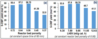
The 5-CMF synthesis process in UVUS-RPBR was initially explored using various reactor bed porosities (Fig. 9) while maintaining the feed space time in UVUS-RPBR at the same level as the batch optimized time (60 min), under otherwise optimized batch process conditions, viz., 5 (∅ChCl/SS), 80 °C (ΩT), and 1.5 (∅S101/TiO2). Moreover, the UV and US specific power inputs for the UV (0.40 watt per ml) and US (2.5 watt per ml) energy system were also kept at the same level as in the batch process using regulators. According to Fig. 9(a), it can be observed that at a constant space time of 60 min, the UVUS-RPBR with a reactor bed porosity of 0.56 could render almost identical 5-CMF yield (58.75 mol%) compared to the UVUS-BR (60.54 mol%). On the other hand, when the bed porosity remained constant at 0.56, any liquid hourly space velocity (LHSV) exceeding 9.95 ml gcat.−1 h−1 (total syringe pump infused rate of 126 ml h−1) led to an observable reduction in the 5-CMF yield (according to Fig. 9(b)), as anticipated. A decrease in the 5-CMF yield was also observed at LHSV below 9.95 ml gcat.−1 h−1 (Fig. 9(b)), which could potentially be attributed to the degradation of 5-CMF into levulinic acid due to uneven mixing of the organic phase with the aqueous phase. The reduced axial mixing in the biphasic fluid occurred due to a lower Peclet number when the advective transport rate decreased at lower LHSV, which in turn, led to a lower extraction of CMF from the aqueous phase into the organic phase, ultimately resulting in an increased levulinic acid yield.The reusability of the catalysts was also studied in UVUS-RPBR, which revealed that the glass beads-supported TiO2 photocatalyst and S-101 showed no decrease in activity (in terms of the 5-CMF yield) up to 6 h, with a constant space time yield of 0.0191 mol L−1 h (same as 58.75 mol% of the 5-CMF yield). Afterwards, a decline in the catalyst's activity was observed (<6% in terms of the 5-CMF yield at the 7th h), despite the absence of any detectable leaching of TiO2 from the glass beads. This decrease in activity could potentially be attributed to the surface poisoning of TiO2 caused by chloride ions. Notably, the used glass beads-supported TiO2 photocatalyst can be easily recycled by simply heating it at 120 °C in an oven furnace for one hour.
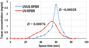
Based on the results obtained from UV-RPBR, we were motivated to delve deeper into the influence of ultrasound (US) on the flow pattern in RPBR. To achieve this, pulse tracer experiments were carried out in RPBR with and without the US system (details given in S4†). The exit-age distribution functions (E(t)) of the tracer in the UVUS-RPBR and UV-RPBR (without US) systems were calculated as a function of time, and the obtained results are demonstrated in Fig. 10. The results revealed that at the RPBR bed porosity of 0.56 and tracer flow rate of 126 ml h−1 (superficial velocity: 0.0023 cm s−1), the obtained mean space time was 58.6 min for UVUS-RPBR and 50.9 min for UV-RPBR. Furthermore, the corresponding Peclet number (Pe) and dispersion number (D) for UVUS-RPBR and UV-RPBR were 119.83, 45.34 and 0.00028, 0.00076, respectively. A comparison of the dispersion numbers inferred that the nonideality in the RPBR reactor could be substantially reduced (more than 60%) by incorporating the US system, which eventually increased the efficacy of UVUS-RPBR in terms of the 5-CMF yield.
Notably, for comparison, a tracer test was also conducted in a cylindrical packed-bed reactor to examine the impact of ultrasound (US) under conditions of equal bed porosity and inlet flowrate as the RPBR. The results showed a mean space time of 55.21 min, with a Peclet number (Pe) of 72.08 and a dispersion number (D) of 0.00047. These findings clearly demonstrate that the ultrasound energy exhibited superior performance in reducing the nonuniformity of the velocity distribution in the RPBR when compared to the cylindrical packed bed reactor.
3.6. Simulation study of UVUS-RPBR using ANSYS Fluent software
The local distribution of the flow variables, viz., pressure and velocity in UVUS-RPBR, is not possible to evaluate through standard experimental techniques. However, this data can be readily obtained through CFD simulations. ANSYS Fluent software was utilized to conduct simulations on both UVUS-RPBR and UV-RPBR systems, aiming to investigate the influence of ultrasound (US) on the distribution of the local velocity and pressure.In the simulation study, the deformation of the rectangular (150 mm × 50 mm × 30 mm) bed reactor (RBR) without packing was first studied during ultrasonication using the ANSYS Workbench. In the ANSYS Workbench, the Transient Structural module was integrated with the Fluent module, as depicted in Fig. S2.† To apply voltage to the piezoelectric material, APDL commands were employed, and the material properties are provided in Fig. S3.† The results indicated that when RBR was exposed to US energy at a feed flow rate of 126 ml h−1, it exhibited a maximum vibration amplitude of 0.237 mm, as illustrated in Fig. 11.
Once the vibrational amplitude of the rectangular bed reactor (RBR) was assessed, the transient simulation study (Fig. S4 and Table S5†) focusing on the local velocity and pressure distribution within the RPBR (RBR with catalyst packing) was investigated. To simplify the computational complexity, a 2D computational domain of 150 mm in length and 30 mm in height was considered.
In the RPBR, the flow pattern was significantly influenced by the presence of large glass bead-coated TiO2 particles (with a diameter of 4.2 mm) compared to the S-101 fine particles (with a diameter of 0.1 mm). Therefore, to model the RPBR with a bed porosity of 0.56, the 2D domain was filled with equally spaced 145 circles with a diameter of 4.2 mm. Finally, to simulate the vibrational motion of each circle and the reactor wall with an amplitude of 0.237 mm and frequency of 20 kHz during ultrasonication, a user-defined function (UDF) was used, and the flow variables in UVUS-RPBR were simulated.
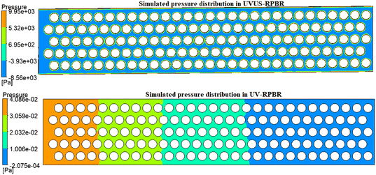
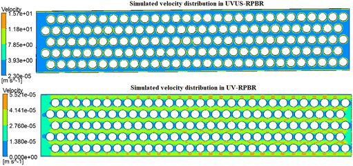
The simulation results demonstrated that under US energy, the RPBR exhibited uniform local pressure (Fig. 12) and velocity (Fig. 13) distributions, aligning well with the findings from the experimental residence time distribution (RTD) study (low dispersion number: 0.00028). On the other hand, in the UV-RPBR case, Fig. 12 and 13 revealed a non-uniform pressure distribution and nearly zero velocity between the circles, indicating that the introduction of US energy substantially enhanced the non-ideal behavior of the RPBR.
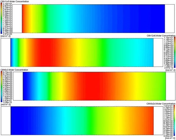
After analyzing the effect of US energy on RPBR in the simulation study, the batch reaction kinetic parameters were employed to simulate the 5-CMF reaction in UVUS-RPBR. Here, the RPBR was considered as a porous bed with a porosity of 0.56 and internal resistance of 0.1. Moreover, it was also considered that the SS-to-5-CMF synthesis reaction steps only occurred in the porous bed (on the catalyst's surface). Finally, a user-defined function with DEFINE_VR_RATE macro was used to simulate the 5-CMF synthesis process under optimized conditions. Fig. 14 shows the simulated molar concentration of SS (C6H11O5), glucose (C6H12O6), 5-HMF (C6H6O3) and 5-CMF (C6H5O2Cl) across the reactor length of the UVUS-RPBR, which are similar to the experimentally obtained glucose, 5-HMF and 5-CMF yields of 13.2 mol%, 14.60 mol% and 60.54 mol% at the reactor outlet.
3.7. Environmental impacts of the SS-to-5-CMF synthesis process
The LCA analysis of the overall 5-CMF synthesis process revealed that the most prominent normalized (person/year) “ReCiPe Midpoint (H) V1.13” indicators (Fig. 15(a)) were marine ecotoxicity, freshwater ecotoxicity, human toxicity, freshwater eutrophication, marine eutrophication and photochemical oxidant formation. Moreover, Fig. 15(b) demonstrates the individual contributions of each process to the overall environmental impacts. It reveals that, among all the processes, the 5-CMF synthesis process in UVUS-RPBR had the highest environmental impacts in all of the impact indicators, except for the photochemical oxidant formation indicator. The utilization of soluble starch was identified as the main cause of the highest environmental impacts observed in the 5-CMF synthesis process. To mitigate these impacts, exploring alternatives to this particular starch source, such as lignocellulosic biomass, could be beneficial. Notably, the product separation process is found to have the most significant impact on the photochemical oxidant formation indicator, primarily attributed to the presence of cyclohexane. A detailed investigation into the contribution of different solvents used in the product separation process is provided in section 3.3.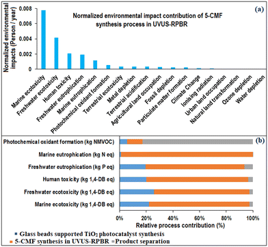 | ||
| Fig. 15 (a) Normalized environmental impacts of the 5-CMF synthesis process. (b) Relative process contributions in the total environmental impacts of the 5-CMF synthesis process. | ||
Fig. 16 illustrates the comparative environmental impacts of the optimized 5-CMF synthesis process associated with the UVUS-RPBR and UV-RPBR systems, which clearly revealed that the UVUS-RPBR resulted the lowest impacts in all prominent indicators in comparison with UV-RPBR.
 | ||
| Fig. 16 Environmental impacts of the 5-CMF synthesis process associated with UVUS-RPBR and UV-RPBR [the maximum result of each indicator was set to 100%]. | ||
3.8. Comparative study with the previously reported relevant works on the 5-CMF synthesis process
The present work's results are compared with previous studies, which are tabulated in Table 6. However, no work was reported on the 5-CMF synthesis in the packed bed reactor involving reusable heterogeneous TiO2 and S-101 dual catalysts. Brasholz et al.18 and Kohl et al.19 achieved high 5-CMF yields (>80 mol%) from fructose using concentrated HCl (32%) in a small high pressure (10 bar) plug flow reactor (reaction volume: 10 ml; inner diameter: 1 mm) with short residence times (<2 min). However, the authors noted that at reaction temperatures exceeding 80 °C, pressure fluctuations within the reactor became significant due to the formation of humics. Moreover, in the present study, we obtained higher 5-CMF yields at much lower pressure (atmospheric pressure) from glucose compared to the work by Brasholz. Besides, when synthesizing 5-CMF from fructose, we achieved the same yield as reported by Chen et al.7 at a lower temperature using the reusable heterogeneous catalyst (S-101 and TiO2) under the synergistic effects of UV-US irradiation, which could mitigate harmful environmental impacts. Significantly, this study achieved greater space–time yields (mol L−1 h−1) of 5-CMF from all of the utilized feedstocks (fructose, glucose, and SS) compared to those reported by Chen et al.7| Reaction condition | Catalyst | Heating system | Extracting solvent | Feedstock | 5-CMF yield (mol%) | Space time yield of 5-CMF (mol L−1 h−1) | Ref. |
|---|---|---|---|---|---|---|---|
| 120 °C; 30 min; batch reactor | ChCl–AlCl3·6H2O–oxalic acid | Conventional | DCE | Fructose | 86 | 0.023 | 7 |
| Sucrose | 80 | 0.021 | |||||
| Glucose | 70 | 0.019 | |||||
| Cellulose | 30 | 0.008 | |||||
| Bamboo | 29 | 0.0077 | |||||
| 100 °C; 1.67 min; PFR | HCl | Conventional | DCM | Fructose | 81 | 0.132 | 18 |
| Glucose | 58 | 0.184 | |||||
| 90 °C; 1.5 min; PFR | HCl | Conventional | DCE | Fructose | 85 | 0.215 | 19 |
| 80 °C; 60 min batch reactor | S-101 and TiO2; ChCl | UVUS | Cyclohexane | Fructose | 86.0 | 0.028 | This work |
| Specific power input: 2.9 watt per ml | Glucose | 72.5 | 0.0235 | ||||
| SS | 60.54 | 0.020 | |||||
| 80 °C; 60 min packed bed reactor | S-101 and TiO2; ChCl (bed porosity: 0.56) | UVUS | Cyclohexane | Fructose | 86.0 | 0.028 | This work |
| Specific power input: 2.9 watt per ml | Glucose | 72.0 | 0.0235 | ||||
| SS | 58.75 | 0.0191 |
4. Conclusions
5-CMF from soluble starch (SS) was energy-efficiently synthesized through an environment-friendly synthesis protocol in both batch (UVUS-BR) and continuous-flow rectangular packed bed reactors (UVUS-RPBR) employing the heterogeneous Smopex-101 and TiO2 dual catalytic system in the presence of cyclohexane as the extracting solvent under UV-ultrasound (US) irradiations. At mild optimal operating conditions (80 °C, 60 min), the synergistic effect of the US-UV irradiation system in UVUS-RPBR significantly enhanced the 5-CMF yield (58.75 mol%) compared to the individual US (<8 mol%) and UV (41.50 mol%) irradiation systems. Moreover, the RTD analysis and ANSYS simulation study revealed that the nonideality of RPBR could be greatly reduced under ultrasound energy (63% less compared to the absence of the US system). Additionally, the efficacy of UVUS-RPBR was successfully simulated using ANSYS Fluent software for 5-CMF synthesis by incorporating experimentally evaluated heterogeneous surface reaction kinetic model parameters, which can be useful for scale-up of such reactor. The LCA study showed that the energy-efficient UVUS-RPBR resulted in 16–20% less environmental impacts in marine ecotoxicity, freshwater ecotoxicity, and human toxicity compared to the UV-RPBR (conventionally heated) system during the 5-CMF synthesis process. Notably, based on comparative LCA analysis, cyclohexane was identified as the most environmentally advantageous solvent for extracting 5-CMF. The development of UVUS-RPBR has the potential to pave the way for the proficient continuous synthesis of 5-CMF utilizing this dual heterogeneous catalytic system, and thus opens a new avenue towards the process scale-up for industrial application.Author contributions
Sourav Barman: conceptualization, methodology, software, data collection & interpretation, validation. Rajat Chakraborty: conceptualization, visualization, supervision, funding acquisition, review, editing & overall guidance. All authors read and approved the final manuscript.Conflicts of interest
There are no conflicts to declare.Acknowledgements
The financial support of DHESTBT (ST/P/S&T/4 G-2/2018) (Government of West Bengal, India) is gratefully acknowledged.References
- M. Mascal, ChemSusChem, 2015, 8, 3391–3395 CrossRef CAS.
- M. Mascal, ACS Sustainable Chem. Eng., 2019, 7, 5588–5601 CrossRef CAS.
- B. Chen, Y. Feng, S. Ma, W. Xie, G. Yan, Z. Li, J. Sperry, S. Yang, X. Tang, Y. Sun and L. Lin, J. Energy Chem., 2023, 1, 421–428 CrossRef.
- M. Mascal and E. B. Nikitin, ChemSusChem, 2009, 2, 859–861 CrossRef CAS.
- S. B. Onkarappa and S. Dutta, ChemistrySelect, 2019, 5, 7502–7506 CrossRef.
- M. Zuo, Z. Li, Y. Jiang, X. Tang, X. Zeng, Y. Sun and L. Lin, RSC Adv., 2016, 6, 27004–27007 RSC.
- B. Chen, Z. Li, Y. Feng, W. Hao, Y. Sun, X. Tang and L. Lin, ChemSusChem, 2021, 14, 847–851 CrossRef CAS.
- S. Pumrod, A. Kaewchada, S. Roddecha and A. Jaree, RSC Adv., 2020, 10, 9492–9498 RSC.
- S. K. Yedla, B. Velaga, S. Choudhury, A. Namdeo, A. K. Golder and N. R. Peela, React. Chem. Eng., 2020, 5, 1738–1750 RSC.
- M. Nayebi, A. Faraji, A. Bahadoran, Z. J. Othman, S. Arghavani, P. G. Kargar, S. M. Sajjadinezhad and R. S. Varma, ACS Appl. Mater. Interfaces, 2023, 15, 8054–8065 CrossRef CAS.
- M. Cybularczyk-Cecotka, J. Szczepanik and M. Giedyk, Nat. Catal., 2020, 3, 872–886 CrossRef CAS.
- J. Ma, C. Zhu, K. Mao, W. Jiang, J. Low, D. Duan and Y. Xiong, Nat. Commun., 2023, 14, 1410 CrossRef CAS.
- M. Singh, N. Pandey and B. B. Mishra, RSC Adv., 2020, 10, 45081–45089 RSC.
- B. A. Smith, P. Champagne and P. G. Jessop, Chem.: Methods, 2021, 1, 438–443 CAS.
- S. W. Breeden, J. H. Clark, T. J. Farmer, D. J. Macquarrie, J. S. Meimoun, Y. Nonne and J. E. Reid, Green Chem., 2013, 15, 72–75 RSC.
- C. Xiouras, N. Radacsi, G. Sturm and G. D. Stefanidis, ChemSusChem, 2016, 9, 2159–2166 CrossRef CAS.
- S. Barman and R. Chakraborty, J. Environ. Chem. Eng., 2021, 9, 106736 CrossRef CAS.
- M. Brasholz, K. Von Kaenel, C. H. Hornung, S. Saubern and J. Tsanaktsidis, Green Chem., 2011, 13, 1114–1117 RSC.
- T. M. Kohl, B. Bizet, P. Kevan, C. Sellwood, J. Tsanaktsidis and C. H. Hornun, React. Chem. Eng., 2017, 2, 541–549 RSC.
- C. A. Antonyraj, A. J. Chennattussery and A. Haridas, Int. J. Chem. Kinet., 2021, 53, 825–833 CrossRef CAS.
- P. Rojahn, K. D. Nigam and F. Schael, Chem. Eng. J., 2022, 450, 138243 CrossRef CAS.
- S. Chatterjee, S. Barman and R. Chakraborty, RSC Adv., 2016, 6, 74278–74287 RSC.
- H. S. Fogler, Essentials of Chemical Reaction Engineering, Pearson Education, 2010 Search PubMed.
- L. Atanda, M. Konarova, Q. Ma, S. Mukundan, A. Shrotri and J. Beltramini, Catal. Sci. Technol., 2016, 6, 6257–6266 RSC.
- D. Bose, S. Barman and R. Chakraborty, Sustainable Mater. Technol., 2020, 24, e00162 CrossRef CAS.
- F. Wu, Z. Zhou and A. L. Hicks, Environ. Sci. Technol., 2019, 53, 4078–4087 CrossRef CAS PubMed.
- Echemi. (n. d). retrieved January 16, 2021, from https://www.echemi.com/weekly-price-list.html.
- Y. Luo, J. Z. Luo, X. J. Yue, Y. J. Song, G. W. Chu, Y. Liu, Y. Le and J. F. Chen, Chem. Eng. J., 2018, 331, 510–516 CrossRef CAS.
- F. J. Navarro-Brull, A. R. Teixeira, J. Zhang, R. Gómez and K. F. Jensen, Ind. Eng. Chem. Res., 2018, 57, 122–128 CrossRef CAS.
Footnote |
| † Electronic supplementary information (ESI) available. See DOI: https://doi.org/10.1039/d3re00406f |
| This journal is © The Royal Society of Chemistry 2024 |


