Development of a continuous melt reactor for an acid-mediated decarboxylation†
Gordon
Brezicki
,
Josef M.
Maier
,
Julian P.
Chesterman
,
Saad
Bux
,
Brenden T.
Herrera
,
Eric
Van Dyke
,
Wesley
Niswander
,
Jacob
Saxon
,
Luke
Rogers
 * and
D. Tyler
McQuade
*
On Demand Pharmaceuticals, 1550 East Gude Drive, Rockville, 20852 Maryland, USA. E-mail: lrogers@ondemandpharma.com; tmcquade@ondemandpharma.com
First published on 27th February 2024
Abstract
Midazolam, a sterile injectable sedative, was in high demand during the COVID-19 pandemic. We developed a synthetic process where the final decarboxylation step provided high yield and excellent midazolam/isomidazolam selectivity when conducted as a hot-melt in the presence of a strong acid. Herein, we describe a new continuous reactor to conduct the acid-mediated high-temperature melt decarboxylation reaction. In particular, we will present a novel melt reactor composed of heated stacked aluminum plates that accepts a solid feed, melts the feed, and conveys the melt through a reaction zone using gravity. Several aspects of the plate reactor required design iteration and optimization, including the melting zone, the specific shape of the liquid outlet of each plate, control of the flow rate and residence time using the temperature of the melting zone, and powder feeding strategy. After optimization, a small-scale prototype was constructed, and the robustness was assessed with two production campaigns lasting approximately 13 and 28 hours. The reactor consistently produced midazolam with a >95% instantaneous yield and produced 691 g of crude midazolam across the two runs. Moreover, the melt reaction suppresses the formation of isomidazolam, a common and difficult to purge impurity, to levels below 0.3 liquid chromatography area percent.
Introduction
Midazolam is a tricyclic benzodiazepine used as a sedative.1 At the height of the COVID-19 pandemic, increased demand for midazolam led to critical shortages. Generic sterile injectables, such as midazolam, are prone to shortages due to their low profit margins, which often results in few manufacturers, thereby threatening the security of the drug product supply. Supply chains are long and complex, with precursors and active pharmaceutical ingredients (APIs) most often sourced from overseas and access can be strained during crises. We aimed to develop a novel and efficient route for the synthesis of midazolam API for the purposes of domestic manufacturing in the United States.Midazolam production dates back to the 1960s, and in several approaches, the final step in the synthesis (Scheme 1) involves a thermal decarboxylation of the precursor tricyclic acid (TCA, 1). These approaches produced significant amounts of the known isomeric impurity, isomidazolam (3), which must be controlled to a level less than 0.1 liquid chromatography area percent (LCAP). Due to the structural similarity to the desired product, isomidazolam is challenging to purge during purification. In one example, midazolam was produced in a 6![[thin space (1/6-em)]](https://www.rsc.org/images/entities/char_2009.gif) :
:![[thin space (1/6-em)]](https://www.rsc.org/images/entities/char_2009.gif) 1 ratio to isomidazolam via decarboxylation of TCA at 160–230 °C in mineral oil; the midazolam to isomidazolam ratio could be increased to 50
1 ratio to isomidazolam via decarboxylation of TCA at 160–230 °C in mineral oil; the midazolam to isomidazolam ratio could be increased to 50![[thin space (1/6-em)]](https://www.rsc.org/images/entities/char_2009.gif) :
:![[thin space (1/6-em)]](https://www.rsc.org/images/entities/char_2009.gif) 1 by refluxing the crude product in methanol with potassium tert-butoxide.2 More recently, an alternative strategy was reported where TCA was subjected to hydrolysis conditions using HCl to yield the corresponding keto-ammonium hydrochloride salt (referred to as “ring-open”), which could then be heated in N-methylpyrrolidinone (NMP) at 200 °C to facilitate thermal decarboxylation and ring-closure. Using this method in a standard batch reactor or a continuous manufacturing platform, the formation of isomidazolam could be suppressed to 1–3 liquid chromatography area percent.3
1 by refluxing the crude product in methanol with potassium tert-butoxide.2 More recently, an alternative strategy was reported where TCA was subjected to hydrolysis conditions using HCl to yield the corresponding keto-ammonium hydrochloride salt (referred to as “ring-open”), which could then be heated in N-methylpyrrolidinone (NMP) at 200 °C to facilitate thermal decarboxylation and ring-closure. Using this method in a standard batch reactor or a continuous manufacturing platform, the formation of isomidazolam could be suppressed to 1–3 liquid chromatography area percent.3
Attempts to implement the ring-open strategy in a plug flow reactor (PFR) produced elevated levels of isomidazolam that could not be efficiently purified to meet USP monograph specifications. Further, the low solubility of the ring-open hydrochloride salt in NMP hampered throughput and NMP removal was difficult.
The team evaluated alternative acid sources with the objective to identify conditions that both suppressed impurity formation and were amenable to continuous manufacturing. Sulfonic acids such as para-toluenesulfonic acid (PTSA) and benzenesulfonic acid (BSA) were both able to minimize isomerization (<0.4% LCAP isomidazolam) and give high in situ yield (>95%) under solvent-free conditions at 230 °C. Higher equivalents of the sulfonic acids led to improved purity profiles; however, the reaction rate also decreased. To understand the role of the sulfonic acid, the individual components and solid mixture were characterized using thermogravimetric analysis (TGA). When midazolam or PTSA was individually heated to 200 °C, a considerable loss in mass was observed, likely due to thermal decomposition; however, when the solid mixture was heated to 200 °C, the mass loss was dramatically reduced, suggesting there is a unique interaction between the sulfonic acid and TCA/midazolam that stabilizes the starting material and product.
Here, we report the design and construction of a novel continuous melt reactor developed to enable the sulfonic acid – mediated synthesis of midazolam. The reactor design centers around gravity-powered conveyance of the melt through a series of stacked, heated machined aluminium plates. We evaluated and tested several approaches to accommodate the unique requirements of the continuous melt reaction for midazolam synthesis (high temperature, continuous powder feeding, significant off-gassing, corrosive media), including conveyor belt style and screw-extrusion type reactor prototypes. The stacked plate approach ultimately proved best able to address the challenges of the reaction due to its efficient heat transfer (thin liquid layer in direct contact with a heated surface), efficient off-gassing (open pathways that allow easy escape of CO2 generated by decarboxylation), precise residence time control (achieved by tuning the melting temperature and the melting zone geometry), and corrosion resistance (the plates can be coated with a fluoropolymer without risk of physical degradation due to the passive, gravity-powered conveyance).
Iterative reactor design based on kinetic modeling culminated in a small-scale prototype that continuously processed material for up to 28 hours, including start-up and shut-down operations, to produce more than 500 grams of crude midazolam.
Experimental
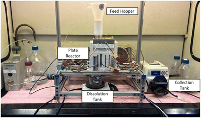
Small scale midazolam synthesis reactions for kinetic modeling were performed on 2.5 gram-scale in glass vials with magnetic stirring in a heating block. The starting material tricyclic acid (TCA) (in-house) and para-toluenesulfonic acid monohydrate (PTSA) (Sigma Aldrich ReagentPlus 98%) were weighed in the appropriate ratios and charged to the vial. The solid mixture was heated to approximately 160 °C to melt the components and remove water from the system without initiating decarboxylation. The density of the melt was measured by weighing a known volume. After density measurement, the vial was heated to the target reaction temperature to initiate the decarboxylation reaction. Aliquots were collected periodically by submerging the tip of a glass pipette in the reaction mixture and transferring the sample to a pre-weighed vial. The vial was weighed after sample collection to determine the mass of sample collected, and the mass was converted to volume via the previously measured density. The melt sample was then dissolved in an appropriate volume of diluent (60/20/20 DI water, acetonitrile, methanol (v:v:v) with 0.04% formic acid) to reach a target concentration for analysis by liquid chromatography-mass spectrometry (LC-MS). Samples were characterized using a Thermo Scientific Vanquish LCMS (Kinetex 2.6 μm C18 100 Å 50 × 4.6 mm column, 254 nm) using a gradient method at 1 mL min−1; the composition of the mobile phase began at 35% 0.1% formic acid in methanol with 65% 5 mM aqueous ammonium formate and was ramped up to 85% 0.1% formic acid in methanol and 15% 5 mM aqueous ammonium formate over 4 minutes and held for one minute for a 5 minute run time. The concentration of the individual components was determined by integrated peak areas that were normalized with response factors. Both TCA and midazolam can exist as a ring-closed and ring-open form. The response factors of both forms were measured, and the total TCA and midazolam concentrations were calculated by summing the concentrations of each of the open and closed forms.Reactions carried out in the small-scale plate reactor prototype were initiated by heating the lower plates to the reaction temperature (230 °C), while the top plate was heated to approximately 120 °C. The top plate was maintained at a lower temperature by placing a PTFE spacer between the top plate and the lower plates. The plates were heated using 120 VAC heating cartridges inserted into holes machined into the plates (two per plate) and controlled by relays. Each plate had a PFA-coated thermocouple inserted into the melt that was used to control the melt temperature via proportional–integral–derivative (PID) control of the heating cartridge duty cycle. The temperature control strategy allowed the melt temperature to be maintained within 5 °C of the setpoint. LabVIEW was used to control the reactor temperatures and to record temperature and flow rate data.
Once the reactor reached the target temperature, the pre-mixed TCA/PTSA powder was manually added to the cylindrical feed hopper to initiate the reaction. As the powder melted and traveled through the reactor, the feed hopper was periodically refilled by monitoring the level in the hopper from a camera mounted above the reactor. As the melt exited the reactor, it was collected into a collection tank placed on a scale to measure the flow rate. The top plate temperature was adjusted based on the measured flow rate to achieve a residence time that produced >95% conversion. Samples were collected by placing a sample vial under the reactor outlet to collect a small amount of the melt. The vial was weighed before and after sample collection, and the midazolam and TCA concentrations were determined in the same manner as the kinetic modeling experiments. Instantaneous yield was calculated by dividing the outlet midazolam concentration by the inlet TCA concentration, and the overall yield was calculated by dividing the total moles of midazolam produced in a production run by the total moles of TCA charged to the reactor.
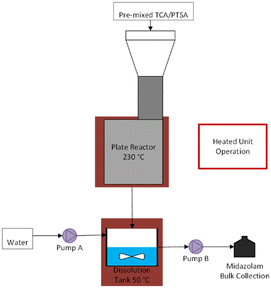
Once the required top plate temperature had been determined, subsequent reactions in the plate reactor prototype had a dissolution unit operation added so that an aqueous solution could be transferred to the extraction/purification steps and directly pumped, rather than a solidified melt that would have to be re-melted and dissolved in water. Continuous dissolution was accomplished by placing a collection tank onto a stir plate. Water was pumped into the dissolution vessel at an initial rate of 2.7 mL min−1 using an Eldex HPLC pump (later varied to try to hit a target of 100 mg mL−1 midazolam in the aqueous solution), and the solution was pumped out of the dissolution vessel using a Masterflex peristaltic pump via a dip tube to maintain a constant volume in the vessel. The dissolution vessel was stirred and maintained at 50 °C. Because the dissolution vessel was no longer on a scale, the reactor outlet flow rate could no longer be directly measured. The final collection vessel for the dissolution outlet was placed on scale so that the reactor outlet flow rate could be measured by mass balance (i.e. subtracting the water flow rate from the dissolution outlet flow rate), but the rate of water evaporation from the dissolution vessel was significant enough to prevent accurate measurement of the reactor outlet flow rate after addition of the dissolution step.
Results and discussion
Kinetic modeling
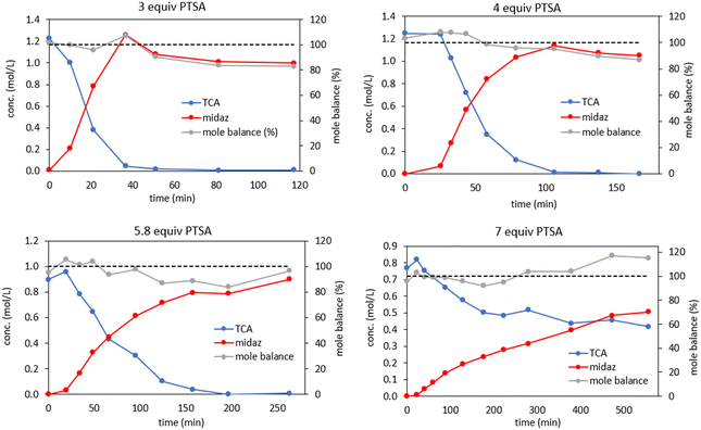
Kinetic studies of the TCA decarboxylation reaction were performed to develop a kinetic model that could be used to design a continuous reactor. Initial experiments varied the molar equivalents of PTSA to determine the reaction orders of PTSA and TCA. By varying the equivalents of PTSA in the absence of solvent, the starting concentration of both PTSA and TCA were also varied. The concentration profiles of the reaction at 200 °C for different PTSA equivalents are shown in Fig. 1. In agreement with earlier studies, higher equivalents of PTSA decreased the reaction rate (Fig. 2).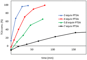 | ||
| Fig. 2 Effect of PTSA equivalents on TCA conversion at 200 °C. The lines are for illustrative purposes and are not intended to imply a modeled system. | ||
Using DynoChem (Scale-Up Systems), we attempted to fit the data to a model to understand the mechanism and elucidate the role of PTSA in suppressing the reaction rate. Satisfactory fits were obtained by fitting concentration data for the four reactions at different PTSA concentrations to simple first order models in which the rate depends only on the concentration of TCA. The TCA decarboxylation reaction is performed as a solvent-free melt, and the molar equivalents of PTSA are several times greater than TCA, PTSA effectively acts as the solvent (i.e. TCA dissolves into the melted PTSA), and so we therefore assumed that the PTSA concentration was constant for each reaction. Moreover, the overall reaction stoichiometry of TCA decarboxylation suggests that PTSA is not consumed. However, because the effect of PTSA concentration is no longer explicitly described in the model, a different observed first order rate constant (that implicitly includes the effect of PTSA concentration on the reaction rate) is obtained for each experiment. Because the effect of PTSA concentration is included in the observed rate constants and the resulting first order model does not explicitly describe the effect of PTSA, the model does not allow the reaction to be optimized with respect to PTSA concentration. With this in mind, we chose to move forward with reactor development using 5.8 equivalents PTSA, which afforded an acceptable balance between reaction rate and impurity suppression.
Analysis of the mole balance profile (calculated by dividing the sum of the midazolam and TCA concentrations by the initial TCA concentration) in Fig. 1 revealed a trend: for three and four equivalents of PTSA, the mole balance dropped below 100% as the reaction progressed, while the mole balance for 7 equivalents of PTSA increased above 100% as the reaction progressed. With 5.8 equivalents of PTSA, the mole balance remained close to 100%. These results are consistent with our previous hypothesis of the formation of an ion pair species between TCA/midazolam and PTSA. With less PTSA, the mole balance may drop below 100% due to insufficient quantity of PTSA available to stabilize TCA/midazolam, resulting in evaporation and/or decomposition. Similarly, with more PTSA, the mole balance exceeding 100% could be explained due to evaporation and/or decomposition of PTSA due to insufficient TCA/midazolam to stabilize PTSA, effectively increasing the concentration of TCA/midazolam in the melt. As mentioned previously, significant mass loss was observed when PTSA and midazolam were heated individually, but far less mass was lost when they were mixed prior to heating, consistent with a strong stabilizing interaction.
An additional experiment at 220 °C (5.8 equiv. PTSA) was performed to fit the activation energy. The following kinetic model was used to fit a first order rate constant and activation energy for TCA decarboxylation using 5.8 equivalents PTSA:
| rTCA = −k × [TCA] | (1) |
 | (2) |
| Tref = 200 °C |
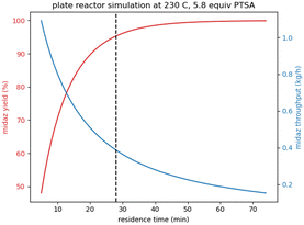
To validate the kinetic model, a validation experiment was performed at 230 °C with 5.8 equiv. PTSA. Fig. 3 shows a comparison between the experimentally measured concentration profile and the model-predicted profile. Based on the good agreement between the model and the experimental results, we used the model to design a continuous reactor for the decarboxylation. While the satisfactory fit between the first order model and the validation experiment is insufficient to prove the mechanistic validity of the model, it was deemed sufficient for use in estimating an initial reactor size to determine the feasibility of our approach.
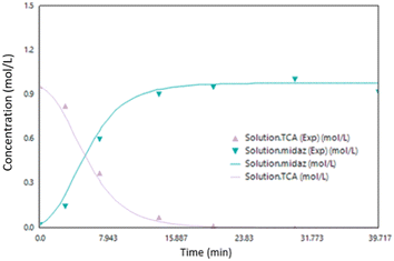 | ||
| Fig. 3 Kinetic model validation experiment for the synthesis of midazolam at 230 °C with 5.8 equiv. PTSA (midaz = midazolam). | ||
Reactor design
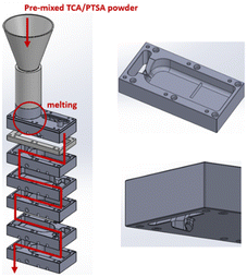
Inspired by the efficient heat transfer of commercially available plate-like reactors,5,6 we set out to design a custom plate-style reactor that could accommodate the unique features of the melt reaction. The primary challenges in designing a continuous melt reactor were the requirements for a method to charge solids as feeds, and a control mechanism for residence time in the absence of pumps that can be adjusted to control flow rates. To address these challenges, we conceived a gravity-fed “stacked-plate” reactor (Fig. 4) that would accept solid powders as inputs, facilitate the transition of the two mixed powders from solid to liquid, and maximize the liquid surface area to volume ratio to precisely control the high temperature decarboxylation. The reactor design resulted in a stack of machined aluminum plates arranged in an alternating pattern where the melt would flow from top to bottom. The top plate would be affixed with a feed hopper where pre-mixed TCA and PTSA powder can be manually added. The temperature of the plates would be controlled by cartridge heaters inserted into holes drilled into the bottom of the aluminum plates. The melting rate, and therefore the liquid flow rate through the reactor and resulting residence time, would be controlled by adjusting the top plate temperature – a higher temperature results in faster melting and thus a higher flow rate. Each opening between plate levels was designed to be large enough to exhaust the CO2 produced avoiding pressure increases.
The liquid level of each plate was defined by the height of a weir at the outlet of the plate that governed the working volume. The target liquid height was <5 mm to maintain a high surface area to volume ratio, minimize temperature gradients, and maximize heat transfer. The plate outlet includes a “drip lip” to direct the melt straight down and prevent droplets from traveling across the bottom surface of the plate.
The flow of the melt in the plate reactor was modeled using a linear velocity profile where the velocity was zero at the plate surface and two times the average velocity at the top surface of the melt (Fig. 5).
The velocity was assumed to be a function only of y and independent of x. The assumption of a linear velocity profile (i.e. perfect laminar flow) represented the worst-case scenario in terms of deviation of the residence time distribution from ideal plug flow reactor behavior. A material balance on the reactor yields the following equation:7
 | (3) |
The linear liquid velocity is given by:
 | (4) |
The liquid height was assumed to be set by the dam height. Substitution of the rate expression (eqn (1)) into the material balance and integration yields the following expression for the TCA concentration at the reactor outlet:
 | (5) |
The average TCA concentration at the reactor outlet is given by:
 | (6) |
| Cmidazolam = CTCA,0 − CTCA | (7) |
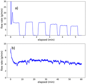
More than 20 prototypes were produced to test and optimize different plate outlet designs via CNC milling or 3D printing (see ESI† for additional information for the prototypes). Initial testing of the flow dynamics was performed with water at room temperature to avoid chemical compatibility issues of the 3D-printed plastic with the test liquid. We found that it was critical to maintain a continuous, steady liquid stream at the plate outlet – if at any point the liquid stream became discontinuous, the liquid front pulled back behind the dam, flow of material stopped, and did not resume until the liquid level reached a level where gravity was able to overcome surface tension. Based on our observations, we designed an outlet that constrained the melt flow to a narrow stream and placed the outlet channel at an angle to slow liquid flow and maintain a continuous stream of material. Additionally, we found that smoothing the transition into the outlet channel facilitates entry of liquid into the channel and prevents buildup above the dam. By providing a buffer zone between the dam and the outlet channel, flow consistency improved and the likelihood of the liquid stream breaking and the liquid front retracting behind the dam decreased.
Fig. 7 shows the flow dynamics in the plates with an unoptimized outlet compared to an optimized outlet. In Fig. 7a, the flow rate versus time profile was intermittent with flow of material continuously stopping and starting. The flow rate was measured by collecting the water exiting the plate on a scale, and water was added to the plate at a constant rate from a burette. Fig. 7b shows consistent flow over time using the optimized plate outlet design.
Design and optimization of the melting zone
While the temperature of the top plate strongly influences the melting rate, it is not the only relevant factor – the melting rate depends on the total heat transfer rate into the solid, which is a function of both the top plate temperature and the top plate surface area that is in contact with the melting solid. The top plate temperature is not infinitely variable – the lower bound is the melting point of PTSA (106 °C, monohydrate). If the flow rate is too high (resulting in low conversion) near the melting point of PTSA, the surface area of the top plate in contact with the solid would have to be decreased, as the top plate temperature cannot be further decreased to limit the melting rate. Thus, the surface area places a bound on the flow rates that can be achieved by varying the temperature of the top plate. The temperature of the melt will also affect its viscosity, which in turn affects the flow rate and residence time. However, the viscosity of the melt was not able to be measured due to the difficulty of making viscosity measurements of a corrosive melt at high temperature.TCA thermally decomposes before melting – the melt therefore forms first by melting of PTSA, followed by dissolution of TCA in the melted PTSA.
Fig. 10 shows cutaway views of three iterative designs of the melting zone. In the initial design (v1), the powder passed through the opening in the feed hopper and onto the top plate without any restriction around the melting zone. Even at the lowest possible temperature that could be reached while still achieving melting, the observed TCA conversion was approximately 5% – i.e., the melting zone surface area was too high, resulting in a melting/flow rate that was too high and residence time that was too low.
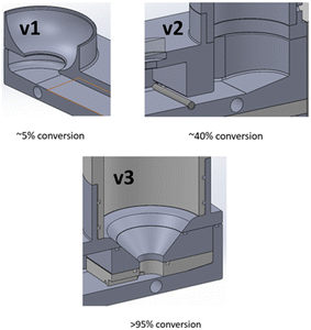 | ||
| Fig. 10 Section views of three iterations of the melting zone design of the top plate and corresponding maximum conversions that were achieved. | ||
In version 2 of the design, we added a “gate” to restrict the melting zone area. The powder melted in the melting zone, and the liquid melt flowed under the gate. Conversion improved to approximately 40% – well below our target of >95% conversion. Further, the flow-restricting gate resulted in the reaction mixture leaking out of the melting zone at the connection points between the top plate, the top plate cover (which includes the gate), and the feed hopper, and necessitated a strategy to prevent leakage of corrosive material at elevated temperatures.
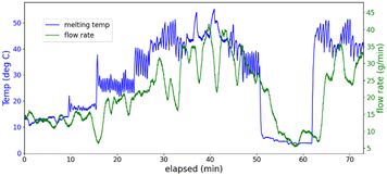
In the v3 design, additional parts were added to the melting zone to funnel the powder into a smaller area to reduce the melting rate (Fig. 10). A PTFE connector was placed between the funnel and the top plate to channel the melt through a narrow opening, and to insulate the funnel from the top plate, thereby lowering the funnel temperature, and minimizing melting occurring prior to the powder mixture reaching the melting zone. Slots for o-rings were added to the top plate, the funnel, and the feed hopper to prevent leaking. Exploded view images of the v2 and v3 designs can be found in the ESI.† The third design resulted in >95% TCA conversion with the temperature of the top plate set to 120–140 °C. As this temperature was significantly below the reaction temperature of 230 °C of the lower plates, PTFE insulation was added between the top plate and the lower plates to ensure the top plate maintained a lower temperature. While in the current iteration of the plate reactor the top plate temperature was adjusted manually to achieve the target conversion, in future iterations a PID control loop will be added for adjusting the top plate temperate to achieve more precise control of the residence time.
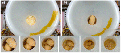
The team decided to take advantage of the powder agglomeration. When the two solids were combined and aged overnight in conical tubes, the solid mixture could be easily removed from the tubes as solid plugs. The plugs could be transferred by the operator from the conical tubes into the feed hopper and the diameter of the plugs relative to the cylindrical feed hopper allowed them to easily travel down the hopper without clogging (Fig. 11b). Fig. 11c shows a time lapse image of the powder plugs traveling down the feed hopper and melting. Tubes of pre-mixed powder could be stored for several weeks at −20 °C and used without incident. Storage at room temperature for more than a day caused challenges with dislodging the plug from the conical tube.
For the first run, the process ran smoothly for approximately 13 hours (Fig. 14). After reaching steady state, the reactor consistently gave an instantaneous yield of ≥95% midazolam, and >92 area percent midazolam (determined by liquid chromatography). The variation in the concentrations seen in Fig. 14a can be attributed to adjustments to the flow rate of water that were made to achieve a target midazolam concentration of 100 mg mL−1, the optimum concentration for the downstream purification process. In total, the first production run produced 259 g of midazolam at a throughput rate of 29 g h−1 (Table 1). The final bulk collection had a midazolam liquid chromatography area percent of 96%, and the overall midazolam yield was 77%. The overall yield was less than the instantaneous yield at steady state due to losses during startup and shutdown.
| Run 1 | Run 2 | |
|---|---|---|
| Top plate temperature (°C) | 124 | 120–140 |
| Reaction temperature (°C) | 230 | 230 |
| Midazolam throughput (g h−1) | 29 | 15 |
| Instantaneous midazolam yield (%) | 96 | 98 |
| Overall midazolam yield (%) | 77 | 93 |
| Average midazolam LCAP in bulk collection | 96 | 92 |
| Isomidazolam LCAP | <0.3 | <0.4 |
| Total midazolam produced (g) | 259 | 432 |
Fig. 15 shows the results from the second production run, which lasted ∼28 h total (∼21 h at steady state). The steady state results were similar to the first run, with a midazolam yield and liquid chromatography area percent >95%. The total midazolam produced was 432 g, and the midazolam liquid chromatography area percent in the final bulk solution was 92% (Table 1). The overall midazolam yield of 93% was higher than the previous run due to the longer run time, which increased the steady state amount of midazolam produced compared to the startup and shutdown losses. Chromatograms for the production campaign can be found in the ESI.†
The major difference between the first and second runs was the midazolam throughput rate, which was nearly double for the first run compared to the second run. This decrease in throughput was observed while the second run was in progress, and the top plate temperature was gradually increased up to a maximum value of 140 °C to increase the melting rate. We speculate that this decrease in throughput may have been due to residue accumulation in the melting zone and/or plate outlets and will be further investigated. While no visible accumulation was observed, each reaction ended with alternating cycles of water and methanol flushing to both clean the reactor and collect midazolam remaining in the reactor. This flushing may have removed any residues. Fluoropolymer coatings for the aluminum plates will be evaluated, which may inhibit adherence of residues to the plates.
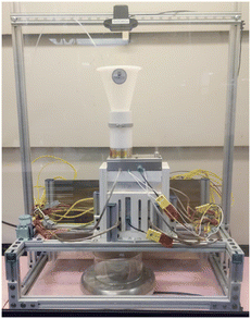
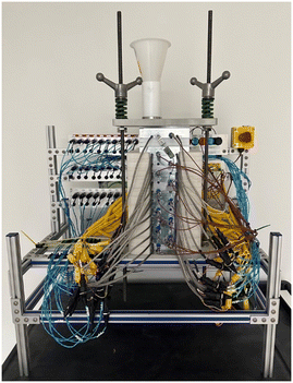
Based on the promising results obtained from testing the small-scale plate reactor prototype, a second-generation scaled-up plate reactor was constructed capable of producing >1 kg per day of midazolam (Fig. 16). The second-generation plate reactor will be evaluated in future experiments.
Conclusions
A prototype continuous melt reactor was developed and tested for synthesis of midazolam via high-temperature acid mediated decarboxylation. A stacked plate reactor was conceived that could accept a solid mixture of reaction components as the input feed, would melt the powder, and convey the melt via gravity through a series of stacked heated aluminum plates to effect decarboxylation of the starting material. A kinetic model developed for the reaction was used to inform reactor design and estimate the required reactor size to produce 1 kg per day of midazolam, including the downstream processing steps. An initial hood-scale prototype was constructed and used to evaluate and optimize various aspects of the reactor, including the use of the temperature of the top plate to control the melt flow rate and residence time, the powder feeding strategy for mitigating feed hopper clogging, and the design of the plate outlet to maintain consistent flow. Finally, the prototype reactor underwent two extended production runs, ranging from 13–28 h, to assess reactor robustness. High conversion to midazolam was consistently observed with instantaneous yields exceeding 95% for a duration of up to 21 h at steady state. Results from testing of the initial small scale plate reactor prototype informed the design and construction of a scaled-up second-generation plate reactor. The stacked plate reactor concept is likely to be applicable to other melt reactions in which continuous operation is desired, as well as high-temperature liquid phase reactions in which both efficient heat transfer and efficient removal of gaseous reaction products is required.Author contributions
GB performed kinetic modeling, designed, and built the plate reactor prototype, developed the control system, designed, and carried out plate reactor experiments, and wrote the manuscript. JM and JC developed the midazolam synthesis chemistry and edited/reviewed the manuscript. SB performed plate reactor experiments and edited/reviewed the manuscript. ED, WN, and JS assisted with plate design and fabrication, developed the powder feeding strategy, assisted with plate reactor experimentation, and edited/reviewed the manuscript. BTH, LR, and DM provided project administration/supervision, and edited/reviewed the manuscript. LR and DM provided funding acquisition.Conflicts of interest
The authors declare the following competing financial interest(s): all authors were affiliated with On Demand Pharmaceuticals (Rockville, MD, USA) at the time of their contributions. On Demand Pharmaceuticals has filed a patent application relating to the synthesis of midazolam (PCT/US2023/074119).Acknowledgements
Development work was supported by the Defense Advanced Research Projects Agency (HR0011-16-2-0029). The views, opinions and/or findings expressed are those of the authors and should not be interpreted as representing the official views or policies of the Department of Defense or the U.S. Government.References
- NIH, Midazolam Compound Summary, PubChem, https://pubchem.ncbi.nlm.nih.gov/compound/midazolam (accessed 2023-03-30) Search PubMed.
- M. K. Dhaon, G. L. Esser, D. A. Davis and A. B. Bhatia, US6512114B1 – Process for the Preparation of Midazolam, June 30, 2003.
- A. Castellin, M. Maggini and P. Donnola, US20110275799A1 – Process for the Synthesis of 4H-Imidazo[1,5-a] [1,4] Benzodiazepines, in Particular Midazolam and salts thereof, May 3, 2013.
- C. R. Schmid, C. A. Beck, J. S. Cronin and M. A. Staszak, Demethylation of 4-Methoxyphenylbutyric Acid Using Molten Pyridinium Hydrochloride on Multikilogram Scale, Org. Process Res. Dev., 2004, 8(4), 670–673, DOI:10.1021/op0499526.
- Corning G1 Reactor, https://www.corning.com/media/worldwide/Innovation/documents/G1_WEB.pdf (accessed 2022-06-10) Search PubMed.
- Chemtrix Protrix, https://www.chemtrix.com/products/protrix (accessed 2022-06-10) Search PubMed.
- M. E. Davis and R. J. Davis, Fundamentals of Chemical Reaction Engineering, Dover Publications, 2012 Search PubMed.
Footnote |
| † Electronic supplementary information (ESI) available: For detailed designs and analytical characterization data. See DOI: https://doi.org/10.1039/d3re00512g |
| This journal is © The Royal Society of Chemistry 2024 |


