DOI:
10.1039/D4RE00372A
(Review Article)
React. Chem. Eng., 2024,
9, 3072-3099
Mixed-conducting ceramic membrane reactors for hydrogen production
Received
31st July 2024
, Accepted 13th September 2024
First published on 26th September 2024
Abstract
Hydrogen is widely used in industrial chemistry and acts as a promising clean energy carrier that can be produced from different hydrocarbons and water. Currently, the main sources of hydrogen are fossil fuels; however, they are associated with large CO2 emissions. Alternatively, green hydrogen produced from water electrolysis using renewable energy is still far from large-scale industrial application owing to the poor reliability of renewable energy and water electrolysis. Therefore, the production of blue hydrogen, coupled with the CO2 capture process, will play a dominant role in the near future in commercial hydrogen production. In this review, membrane reactor technologies based on ceramic-based dense membranes are comprehensively introduced. Membrane reactors are classified into three types according to the properties of the conductive carrier of membrane materials: (1) mixed protonic and electronic conductor (MPEC) membrane reactors, (2) mixed oxide-ionic and electronic conductor (MOEC) membrane reactors, and (3) mixed oxide-ionic and carbonate-ionic conductor (MOCC) membrane reactors. Their working principle, membrane materials, hydrogen sources, operating conditions, and performance are summarized. Finally, the challenges and prospectives of these membrane reactors are discussed for their future development.
1 Introduction
As hydrogen is an important clean energy to substitute fossil fuels and feedstock in chemical synthesis, the demand for hydrogen is continuously increasing. Hydrogen cannot exist in nature in the form of molecules, and thus, it can only be produced from hydrogen-containing sources, such as hydrocarbons, biomass and water.1–3 Currently, most hydrogen is produced via steam reforming, auto-thermal reforming and partial oxidation of hydrocarbons. Although these methods are mature and inexpensive, they emit large quantities of CO2, and thus, the produced hydrogen is called “gray hydrogen”. Therefore, the development of new hydrogen production routes via clean and efficient processes is necessary. In this case, electrical water splitting using renewable energy is one of the most attractive future technologies, and the produced hydrogen is termed “green hydrogen”.4–6 However, it is still far from large-scale industrial application, given the poor reliability of renewable energy and water electrolysis. Therefore, the use of fossil fuels coupled with CO2 capture for the production of hydrogen termed “blue hydrogen” will play a dominant role in the near future in commercial hydrogen production.7,8 To obtain pure hydrogen, the water gas shift reaction (high and low temperature shift reactions) should be followed as the reforming process to convert additional CO into H2 and CO2 mixture, followed by an H2/CO2 separation process.9 Consequently, these complicated processes make the production of “blue hydrogen” an energy-intensive process, especially the downstream separation process.
A membrane reactor is a device that combines the reaction and separation processes in a single unit, thus simplifying the process, reducing capital cost, increasing reaction efficiency10 and thereby making the membrane reactor device a very promising technology. Another typical advantage of membrane reactors is that they can break the thermodynamic equilibrium limits of chemical reactions according to Le Chatelier's principle, and thus, a higher conversion and yield can be achieved. At present, the most widely used technology in hydrogen production membrane reactors is based on Pd-based metal membranes, showing the advantages of high selectivity and high permeability. There are many review papers on Pd-based membrane reactors for H2 production.11–16 However, the high cost, high embrittlement and poor stability of Pd-based membrane reactors in CO– and H2S-containing atmospheres hinder their wide application in industry.17,18
Recently, ceramic-based mixed conductor membranes have attracted significant attention in gas separation due to their low cost, high mechanism strength and chemical stability at high temperatures.19–24 Especially, the high-temperature operation of these ceramic-based membrane reactors enables the coupling of hydrogen production with various chemical reactions to produce high value chemicals. Besides hydrogen permselective membranes, both oxygen and carbon dioxide permselective membranes can also be used for hydrogen production because O2 or CO2 is the main by-product during hydrogen production from H2O or hydrocarbons, respectively. Therefore, ceramic-based membrane reactors for hydrogen production can be grouped into three types according to the charge carriers in their membrane materials, as follows: (1) mixed protonic and electronic conductor (MPEC) membrane reactors, (2) mixed oxide-ionic and electronic conductor (MOEC) membrane reactors, and (3) mixed oxide-ionic and carbonate-ionic conductor (MOCC) membrane reactors. The working principles of these three types of membrane reactors are illustrated in Fig. 1.
 |
| | Fig. 1 Working principles of three types of ceramic-based membrane reactors for H2 production: (a) MPEC membrane, (b) MOEC membrane and (c) MOCC membrane. | |
To distinguish the two sides of the membrane, they are usually named “feed side” and “sweep side”. In this review, the feed side is the side of the reaction that can produce hydrogen, as shown in Fig. 1, and the sweep side is the other side where the permeate species are generated, such as H2 in MPEC membranes, O2 in MOEC membranes and CO2 in MOCC membranes. MPEC membranes can directly separate H2 from an H2-containing mixture gas, as shown in Fig. 1a. Therefore, any reaction that produces H2 can theoretically be used in MPEC membrane reactors. The pure H2 stream can be achieved on the sweep side if vacuum is applied to this side. MOEC membranes are oxygen permeated membranes, and therefore only the H2O splitting reaction can be applied on the feed side in MOEC membrane reactors. As shown in Fig. 1b, pure H2 can be obtained on the feed side after condensation of the outlet gas. To create a positive oxygen partial pressure gradient across the MOEC membrane, a reducing gas (such as syngas and methane) should be purged to the sweep side to consume the permeated oxygen, thus promoting the water decomposition reaction on the feed side. MOCC membranes can permeate CO2 in the form of CO32− at high temperatures, as shown in Fig. 1c. Therefore, to obtain a stream with a high H2 concentration, the reaction products on the feed side should only be CO2 and H2. The high-concentration H2 and pure CO2 can be obtained on the feed side and sweep side, respectively, if vacuum is applied to the sweep side.
The aim of this review is to summarize the recent development of these three types of ceramic-based membrane reactors for hydrogen production, analyzing the effect of membrane types, chemical reactions, materials, and operating conditions on the hydrogen production rate and stability performance.
2 MPEC membrane reactors
2.1 Chemistry of MPEC membrane reactors for hydrogen production
According to the working principle of MPEC membranes, H2 can be produced through methane reforming, dehydrogenation of alkanes, and water gas shift (WGS) reactions in MPEC membrane reactors,25 as shown in Fig. 2. There are four main steps in hydrogen production using this type of membrane reactor, as follows: (1) hydrogen production via chemical reactions, (2) surface exchange process on the feed side of the membrane reactor, (3) bulk diffusion process of protons and electrons in the membrane, and (4) surface exchange process on the sweep side. The H2 production rate of MPEC membrane reactors can be controlled by the chemical reaction process, surface exchange process, bulk diffusion process, or multi-process.
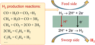 |
| | Fig. 2 Schematic of MPEC membrane reactors for coupling H2 production reactions with H2 separation. | |
A pure hydrogen stream can be achieved on the sweep side in MPEC membrane reactors if steam or vacuum is used on the sweep side. On the feed side, many types of fuels can be fed to the MPEC membrane reactors to produce H2, such as ethane,26 methane,27 methanol28 and biogas.29Table 1 summarizes the hydrogen production performance of MPEC membrane reactors with different membrane materials, catalysts and operating conditions. It should be noted that if low-concentration hydrogen was used as the feed gas, pure hydrogen can also be collected on the sweep side.25,30 However, in this case, the obtained pure H2 is not produced by a chemical reaction, which does not belong to the concept of membrane reactors, and thus will not be reviewed herein. Those who are interested in this situation can read other review papers in the literature.31–34
Table 1 Summary of hydrogen production using MPEC membrane reactors
| Membrane |
Catalyst |
Thickness (μm) |
Feed gas/sweep gas |
T (°C) |
H2 production rate (mL cm−2 min−1)/H2 recovery (%) |
Stability |
Ref. |
| BCFZY: BaCo0.4Fe0.4Zr0.1Y0.1O3−δ, NMW: Nd5.5Mo0.5W0.5O11.25−δ, SCZE: SrCe0.7Zr0.2Eu0.1O3−δ, SCZ: SrCe0.8Zr0.2O3−δ, BCF8515-BCF1585: 50 mol% BaCe0.85Fe0.15O3−δ-50 mol% BaCe0.15Fe0.85O3−δ, hf: hollow fiber, and t: tube. |
| BCFZY |
— |
800 |
3%H2O 1.25%C2H6–Ar/N2 |
700 |
0.16/13.3% |
100 h at 700 °C |
26
|
| NMWhf |
Ni-NMW |
26 |
40%NH3–He/N2 |
750 |
0.12/∼1% |
75 h at 750 °C |
35
|
| BCF8515-BCF1585 |
Ni/Al2O3 |
600 |
11.6%H2O-8.6%CH4–N2/3%H2O–He |
820 |
0.56/18.8% |
100 h at 900 °C |
36
|
| 940 |
0.98/31.2% |
| SCZEt |
Ni-SCZ |
33 |
50%CH4–CO2/He |
900 |
0.2/14.3% |
— |
37
|
| SCZEt |
Ni-SCZ |
33 |
50%CH4-25%CO2-25%H2O/He |
900 |
0.4/10% |
— |
| SCZEt |
Ni-SCZ |
33 |
66%H2O-33%CO-Ar/He |
900 |
0.12/8% |
200 h at 900 °C |
38
|
| SCZEt |
Ni-SCZ |
33 |
16%H2O-8%CO-Ar/He |
900 |
0.05/14% |
| SCZEt |
Fe/SiO2 |
20 |
90%CH4–Ar/He |
950 |
0.02/47% |
60 h at 1030 °C |
39
|
| SCZEt |
Fe/SiO2 |
20 |
90%CH4–Ar/He |
1050 |
0.07/13% |
2.2 Hydrogen production from syngas
The water gas shift (WGS, eqn (1)) is an important reaction to enhance the hydrogen purity and/or increase the H2/CO ratio in syngas, which is produced by hydrocarbon (methane, biomass, coal, etc.) reforming reactions.40–42| |  | (1) |
In this case, to increase the hydrogen production rate, the CO conversion should be maximized. Therefore, the WGS reaction usually proceeds in two steps, i.e., a high-temperature (300–550 °C) reaction to accelerate the reaction rate and a low-temperature (200–250 °C) reaction to increase the CO conversion given that that the WGS process is an exothermic reaction.43 However, H2 production by the WGS reaction in MPEC membrane reactors can be operated at high temperatures due to their ability to remove H2in situ.44Fig. 3a shows the working principle of MPEC membrane reactors for coupling the WGS reaction with the in situ H2 removal process. Li et al.38 fabricated a membrane reactor based on a dense SrCe0.7Zr0.2Eu0.1O3−δ (SCZE) membrane on a tubular Ni-SrCe0.8Zr0.2O3−δ support. In the membrane reactor, the CO conversion of 90% was obtained with an H2O/CO feed ratio of 2/1 at 900 °C, which is 44% higher than the thermodynamic limitations, as shown in Fig. 3b. The total H2 production rate was 0.675 and 0.742 mL cm−2 min−1 with an H2O/CO feed ratio of 1/1 and 2/1 at 900 °C, which is 73% and 42% improvement compared to the thermodynamic calculations (Fig. 3c and d), respectively. The CO concentration on the feed side has a significant effect on the WGS performance, as shown in Fig. 3e. Consequently, the H2 production rate increased from 0.37 to 1.46 mL cm−2 min−1 at 900 °C with an increase in the CO concentration from 8% to 33%, while the H2 recovery decreased from 14% to 8%.
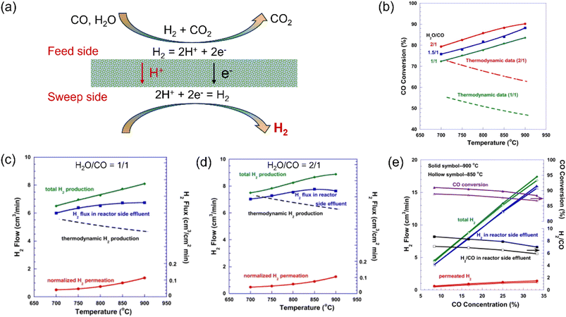 |
| | Fig. 3 Hydrogen production from the water gas shift (WGS) reaction in the MPEC membrane reactor. (a) Schematic, (b) CO conversion as a function of temperature, (c and d) H2 production as a function of temperature with H2O/CO = 1/1 and 2/1, and (e) WGS reaction performance in the membrane reactor as a function of CO concentration with H2O/CO = 2/1. Reproduced with permission from ref. 38. Copyright © 2012, Elsevier. All rights reserved. | |
2.3 Hydrogen production from methane
Currently, methane is the most widely used source for H2 production in industry. The steam reforming of methane (eqn (2)), dry methane reforming (eqn (3)) and non-oxidative methane conversion (eqn (4)) reactions have been applied to MPEC membrane reactors for H2 production, which will be discussed in this section.| |  | (2) |
| |  | (3) |
| |  | (4) |
2.3.1 Steam methane reforming.
Steam methane reforming (SMR) is the main process for industrial hydrogen production, which is a strong endothermic reaction and is mainly controlled by the thermodynamic equilibrium process. As shown in eqn (2), the produced syngas has an H2/CO molar ratio of 3, which requires further adjustment to get an H2/CO ratio of 2 for the subsequent F–T synthesis or further purified to produce pure H2 by the WGS reaction and multiple separation steps. Membrane reactors equipped with an MPEC membrane can remove the H2 from the reaction spot, which shifts the reaction towards the products, and thereby enhances the methane conversion due to Le Chatelier's principle.
Xia et al.36 used a 50 mol% BaCe0.85Fe0.15O3−δ-50 mol% BaCe0.15Fe0.85O3−δ (BCF8515-BCF1585)-based MPEC membrane reactor loaded with an Ni/Al2O3 catalyst to demonstrate this concept, as shown in Fig. 4a. In their membrane reactor, the H2/CO ratio significantly decreased from 3.0 to ∼2.3 with in situ H2 removal by the MPEC membrane at 820 °C (Fig. 4b). As the temperature increased from 820 °C to 940 °C, the H2 production rate increased from 0.56 to 0.98 mL cm−2 min−1, as shown in Fig. 4c, resulting in a further decrease in the H2/CO ratio to 1.95. The BCF8515-BCF-1585-based membrane reactor exhibited good stability at 900 °C with a CH4 conversion of 90%, CO selectivity of 90% and H2 production rate of 0.83 mL cm−2 min−1 (Fig. 4d). Therefore, the MPEC membrane reactor is quite suitable for H2 production via the SRM reaction due to the fact that the syngas stream with an H2/CO ratio of 2 and a pure H2 stream can be obtained simultaneously on the feed side and sweep side, respectively.
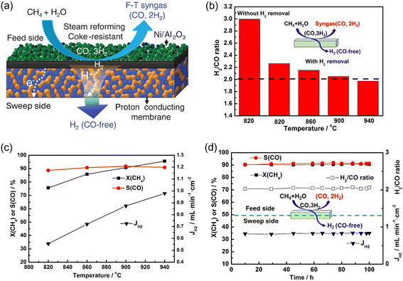 |
| | Fig. 4 Hydrogen production from the steam methane reforming (SMR) reaction in the MPEC membrane reactor. (a) Schematic; (b) H2/CO ratio and (c) CH4 conversion, CO selectivity and H2 production rate as a function of temperature; and (d) time dependence of CH4 conversion, CO selectivity, H2 production rate and H2/CO ratio at 900 °C. Reproduced with permission from ref. 36. Copyright @ 2019, American Institute of Chemical Engineers. | |
2.3.2 Dry methane reforming.
Besides steam methane reforming, dry methane reforming (DMR) is also promising technology to produce H2 due to the fact that it can eliminate two types of greenhouse gases, CO2 and CH4. However, the DMR reaction is a strong endothermic reaction (eqn (3)) with high energy consumption. The MPEC membrane reactor for the DMR reaction shows potential to increase both the CO2 and CH4 conversion due to the removal of the H2 product. For example, Li et al.37 found that the tubular SrCe0.7Zr0.2Eu0.1O3−δ membrane reactor with Ni-based catalyst showed a CO2 and CH4 conversion of 78% and 87% at 900 °C with 50% CH4-50% CO2 as the feed gas, which is 10% and 14% higher than that of a traditional fixed bed reactor, respectively. As shown in Fig. 5a, the total H2 production rate (feed side + sweep side) and permeation rate (sweep side) were 1.4 and 0.2 mL cm−2 min−1, respectively, from the MPEC membrane reactor at 900 °C. However, the H2/CO ratio in syngas from the MPEC membrane reactor was less than 1 due to the in situ removal of H2 and the reverse water gas shift (RWGS) reaction, as shown in Fig. 5b. To increase the H2/CO ratio on the feed side in the membrane reactor for liquid fuel production via the F–T process (the required H2/CO ratio is ∼2), Li et al.37 combined the SMR reaction with the DMR reaction in the SCZE-based membrane reactor, in which CH4–CO2–H2O was used as the feed gas. The CO2 and CH4 conversions were 70% and 85%, respectively, at 900 °C with CH4/CO2/H2O feed ratios of 2/1/1. As shown in Fig. 5c, the H2/CO ratio was in the range of 1.7–1.9 and 2.0–2.5 from 700 °C to 900 °C with CH4/CO2/H2O feed ratios of 2/1/1 and 2/1/1.5, respectively. The total H2 production rate was 4.0 mL cm−2 min−1 at 900 °C (Fig. 5c), which is higher than that with CH4/CO2 as the feed gas.
 |
| | Fig. 5 Hydrogen production from dry methane reforming decomposition in the MPEC membrane reactor. (a) H2 production rate with CH4/CO2 feed, (b) H2/CO ratio dependence on temperature with CH4/CO2 feed, and (c) H2 production rate and H2/CO ratio dependence on temperature with CH4/CO2/H2O feed. Reproduced with permission from ref. 37. Copyright @ 2012, Elsevier. All rights reserved. | |
2.3.3 Non-oxidative methane conversion.
The non-oxidative methane conversion (NMC) reaction can produce hydrogen, C2+ hydrocarbons and aromatics, which shows advantages in simplifying the process and circumventing the energy-intensive steps.45–47 However, low methane conversion was obtained under the practical reaction conditions due to both kinetic and thermodynamic limitations. The MPEC membrane reactor was studied for H2 production via the NMC reaction by Sakbodin et al.39 As shown in Fig. 6a, the tubular membrane reactor based on SCZE membrane and loaded with Fe@SiO2 catalyst was used to improve the methane conversion. The CH4 conversion in both the fixed bed reactor and membrane reactor increased with an increase in temperature from 950 °C to 1050 °C, as shown in Fig. 6b and c, respectively, due to the endothermic nature of the methane conversion reaction. At 950 °C, the hydrogen removal ratio of 47% was achieved with the MPEC membrane reactor, which increased the CH4 conversion from 2.1% to 4.4%. At 1030 °C, the CH4 conversion and H2 permeation flux (measured on the sweep side) of the MPEC membrane reactor were 20.6% and 0.064 mL cm−2 min−1, respectively. The yields of both C2 products and aromatics in the MPEC membrane reactor were higher than that in a fixed bed reactor. For the product selectivity, the selectivity for C2 products (∼90% at 900 °C) was much higher than that of the aromatics at low temperatures in a fixed bed reactor. As the temperature increased, the selectivity for aromatics increased in both the membrane reactor and fixed bed reactor. Both the CH4 conversion and H2 permeation flux increased by increasing the He flow rate on the sweep side. The C2 and aromatic product selectivity varied by changing the sweep gas type (He or H2) and the flow rate, as shown in Fig. 6 and e, respectively. No significant deactivation was observed during the stability test at 1030 °C for 50 h in the SCZE-based membrane reactor, with the total product (C2, benzene, and naphthalene) selectivity higher than 99% (Fig. 6f). Thus, the MPEC membrane reactor can tune the product toward C2 and benzene compared to naphthalene by slightly sacrificing the CH4 conversion, which opens up new possibilities for NMC processes.
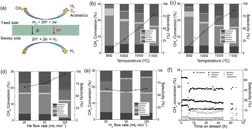 |
| | Fig. 6 Hydrogen production from non-oxidative cracking of methane (CNM) reaction in the MPEC membrane reactor. (a) Schematic, (b) NCM performance in a fixed-bed reactor, (c) NCM performance in the MPEC membrane reactor, (d) NCM performance in the membrane reactor with He as the sweep gas (at 1030 °C), (e) NCM performance in the membrane reactor with H2 as the sweep gas (at 1030 °C), and (f) stability test of the membrane reactor at 1030 °C. Reproduced with permission from ref. 39. Copyright @ 2016, Wiley-VCH Verlag GmbH & Co. KGaA, Weinheim. | |
2.4 Hydrogen production from ethane
The non-oxidative dehydrogenation of alkanes to alkenes (e.g. ethane to ethylene, eqn (5)) has attracted significant attention given that high alkane conversion and alkene selectivity can be obtained at reduced temperatures compared with the benchmark steam cracking technology.| |  | (5) |
However, it still suffers from several limitations, as follows: 1) thermodynamic limitation in conversion; 2) strong endothermal reaction; and 3) coking at high temperatures, which are the major reasons for the performance degradation. Thus, the use of MPEC membrane reactors for the alkane dehydrogenation process will be a suitable choice, given that it can in situ remove the by-product H2, which shifts the thermodynamic equilibrium toward alkene production. Thus, a lower temperature will be allowed in the MPEC membrane reactor, which reduces coke formation and side reactions. In addition, pure H2 can be collected with steam as the sweep gas or vacuum on the sweep side.
Sun et al.26 reported the fabrication of a BaCo0.4Fe0.4Zr0.1Y0.1O3−δ (BCFZY)-based membrane reactor for the non-oxidative hydrogenation of ethane (NODHE) to produce ethylene and hydrogen, as shown in Fig. 7a. The C2H6 conversion, C2H4 selectivity and yield were 70%, 87% and 61%, respectively, at 700 °C with 1.25% C2H6-Ar as the feed gas. A low concentration of C2H6 was used due to the small effective area of the membrane in their study (0.95 cm2). In contrast, the performance of the fixed bed reactor (with a dense Al2O3 disk) was much lower under the same conditions, where a C2H6 conversion of 25% and C2H4 yield of 22% were obtained at 700 °C. In the membrane reactor, the coking resistance could be improved by increasing the steam concentration on the feed side. The BCFZY membrane reactor could be run for more than 100 h at 700 °C without obvious degradation, as shown in Fig. 7b. The H2 production rate on the feed side was around 1.2 mL cm−2 min−1 with 3% humified 1.25% C2H6-Ar as the feed gas at 700 °C. However, the permeated pure hydrogen flux on the sweep side was only 0.16 mL cm−2 min−1 and the corresponding hydrogen recovery was around 13.3%.
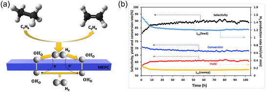 |
| | Fig. 7 Hydrogen production from non-oxidative dehydrogenation of ethane in an MPEC membrane reactor. (a) Schematic and (b) stability test at 700 °C. Reproduced with permission from ref. 26. Copyright @ 2020, Elsevier B.V. All rights reserved. | |
2.5 Hydrogen production from ammonia
Considering the fast development of renewable energy, such as wind and solar, there is an urgent requirement to develop efficient and reliable energy storage technologies. Due to the high energy gravimetric density (33.3 kW h kg−1) and zero carbon emission in the utilization of H2, it is considered one of the most promising carriers to store renewable energy. However, due to its lower volumetric energy density (9.8 kJ L−1) and difficult liquification (−253 °C at 1 bar or 70 MPa at room temperature), it is very expensive to store and transport H2 directly.48–50 Alternatively, ammonia contains 17.65 wt% hydrogen by weight, which is easily liquified (1 MPa at 25 °C), stored and transported, making it a promising and attractive hydrogen energy carrier for on-site hydrogen production. However, both H2 and N2 are produced during the decomposition of ammonia, which requires an additional separation process to obtain a pure hydrogen stream. In this case, MPEC membrane reactors offer several advantages for on-site hydrogen production via the decomposition of ammonia, as follows: 1) pure H2 can be achieved on the sweep side due to the theoretical selectivity of 100% H2; 2) in situ H2 removal from the ammonia decomposition zone can shift the reaction toward H2 production; and 3) low capital cost and high efficiency of the membrane reactor.25
Cheng et al.35 prepared a dual-layer hollow fiber membrane reactor for hydrogen production through ammonia decomposition. The membrane reactor was composed of an Nd5.5Mo0.5W0.5O11.25−δ (NMW) dense MPEC membrane layer and NMW-Ni porous catalytic support layer, as shown in Fig. 8a. At 750 °C, the ammonia conversion of 99% was obtained for the membrane reactor, which was much higher than that of the fixed bed reactor (75%) due to the in situ hydrogen removal ability of the membrane reactor. The ammonia conversion increased with temperature in the membrane reactor, as shown in Fig. 8b, given that the decomposition is an endothermic reaction (eqn (6)). With an ammonia concentration of 40% in the feed gas, the ammonia conversion and hydrogen production rate were 91% and 0.12 mL cm−2 min−1, respectively, at 750 °C. The membrane reactor remained stable for over 75 h (Fig. 8c), while the hydrogen recovery was less than 1%.
| |  | (6) |
Although various hydrogen production reactions can be applied in MPEC membrane reactors, the H
2 recovery on the sweep side is relatively low due to the fact that the MPEC membranes have a low H
2 permeation flux under the operation conditions. The driving force for H
2 permeation is the hydrogen partial pressure gradient across the membrane. In an MPEC membrane reactor, the high hydrogen partial pressure is achieved on the feed side by various chemical reactions, while the low hydrogen partial pressure is created on the sweep side by an inert sweep gas according to the literature. If H
2 consuming reactions are applied to the sweep side, the H
2 permeation flux will be significantly improved in the MPEC membrane reactor. Unfortunately, the chemical reactions that can consume hydrogen cannot be applied on the sweep side because hydrogen is the target product and should be retained. Alternatively, another promising method to achieve a high H
2 production rate and recovery is the use of an external circuit to force H
2 transport from the feed side toward the sweep side.
51–53 However, this will cause some additional issues, such as system complexity and additional power consumption. In this case, readers can refer to other reviews on proton-conducting cells for H
2 production.
25,54–56
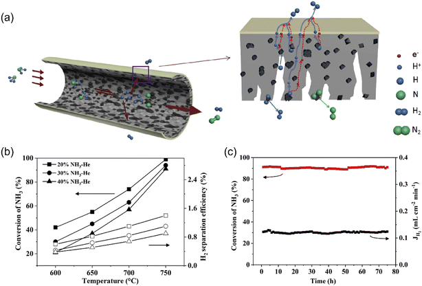 |
| | Fig. 8 Hydrogen production from ammonia decomposition in the MPEC membrane reactor. (a) Schematic, (b) ammonia conversion and hydrogen separation efficiency (recovery) dependence on temperature, and (c) stability test at 750 °C. Reproduced with permission from ref. 35. Copyright @ 2019, Elsevier Ltd. All rights reserved. | |
3 MOEC membrane reactors
3.1 Chemistry of MOEC membrane reactor for hydrogen production
MOEC membranes have been widely studied for O2 separation from air in the past decades.57–62 The working principle of the MOEC membrane for O2 permeation is shown in Fig. 9a. The membrane materials, configuration, microstructure and surface modification all have significant effects on the MOEC membrane permeation performance and long-term stability. There are many good review papers on the O2 permeation process of MOEC membranes.22,63–67 In this section, we only focus on the H2 production via the water splitting process in MOEC membrane reactors.
 |
| | Fig. 9 Schematic of the MOEC membrane used for (a) oxygen separation from air and (b) hydrogen production from water splitting. X: impurity gas. | |
The water splitting reaction (WSR) (eqn (7)) produces a very low concentration of H2 even at very high temperatures due to the small equilibrium constant of the splitting reaction, for example, 0.1% H2 can be produced at 1600 °C.68 Alternatively, a high H2 production rate can be achieved at moderate temperatures if the by-product O2 can be in situ removed by an oxygen permselective membrane.69
| |  | (7) |
Therefore, the H
2 production rate from water splitting can be enhanced by MOEC membrane reactors,
70 given that they have the ability to remove the by-product O
2. On the feed side, steam is fed to the membrane surface and splits into O
2− and H
2, and then the O
2− permeates through the membrane driven by the oxygen partial pressure gradient across the MOEC membrane. On the sweep side, the transported oxygen is immediately consumed by a reducing gas, such as low-purity hydrogen,
71 methane,
72 and syngas,
73 to create a large oxygen partial pressure gradient across the membrane, as shown in
Fig. 9b, which promotes the WSR on the feed side to produce hydrogen. Otherwise, a negligible hydrogen production rate will be obtained on the feed side if an inert gas (
e.g. He) is used as the sweep gas.
74 It should be noted that in MOEC membrane reactors, high-purity hydrogen is obtained on the feed side, as shown in
Fig. 9b, rather than on the sweep side as with traditional hydrogen-permselective membranes. If a low H
2-purity stream is used as the sweep gas in the MOEC membrane reactor, the H
2 separation factor on the feed side can reach 10
3–10
4.
63 Another advantage of MOEC membrane reactors for H
2 production is that different valued-added chemical products can be obtained on the sweep side according to different reducing gas species. Different from the traditional oxygen separation process, both sides of the MOEC membrane reactor in the hydrogen production process are in a reducing atmosphere, and thus many articles and reviews have focused on the membrane materials.
64,75,76 In this review, we focus on the chemical reaction types on the sweep side of MOEC membrane reactors.
The H2 production rate through different MOEC membrane reactors is summarized in Table 2. Obviously, the H2 production rate in MOEC membrane reactors is much higher than that in MPEC membrane reactors, as shown in Table 1. For example, the H2 production rate in the SDC-SSAF MOEC membrane reactor71 and Ni-SCZ MPEC membrane reactor37 were 16.3 and 0.4 mL cm−2 min−1, respectively, at 900 °C.
Table 2 Summary of hydrogen production with MOEC membrane reactors
| Membrane |
Catalyst |
Thickness (μm) |
Feed gas/sweep gas |
T (°C) |
H2 production rate (mL cm−2 min−1) |
Stability |
Ref. |
| PNO: Pr2NiO4+δ, Ni-LST-GDC: Ni-La0.3Sr0.7TiO3−δ-Ce0.9Gd0.1O2−δ, SDC-SFM: Ce0.8Sm0.2O2−δ-SrFe0.75Mo0.25O3−δ, CP: Ce0.85Pr0.15O2−δ, CP-PSFA: Ce0.85Pr0.15O2−δ-Pr0.6Sr0.4Fe0.9Al0.1O3−δ, 70SDC-30STF: 70 wt% Ce0.8Sm0.2O1.9−δ-30 wt% Sr0.92Ti0.5Fe0.5O3−δ, STF: Sr0.92Ti0.5Fe0.5O3−δ, PSFA: Pr0.6Sr0.4Fe0.9Al0.1O3−δ, BFZ: BaFe0.9Zr0.1O3−δ, BSCF: Ba0.5Sr0.5Co0.8Fe0.2O3−δ, CGO: Ce0.90Gd0.10O3−δ, SCF: SrCe0.95Fe0.05O3−δ, SFC: SrFe0.95Ce0.05O3−δ, CPO: Ce0.9 Pr0.1O2−δ, PSM-Ti: Pr0.1Sr0.9Mg0.1Ti0.9O3−δ, BMZ-Ti: BaMg0.1Zr0.05Ti0.85O3−δ, LSF: La0.5Sr0.5FeO3−δ, BCF: Ba0.98Ce0.05Fe0.95O3−δ, LSTF: La0.6Sr0.4Ti0.2Fe0.8O3−δ, SCFZ: SrCo0.4Fe0.5Zr0.1O3−δ, LSCuF: La0.7Sr0.3Cu0.2Fe0.8O3−δ, GSFT: Gd0.1Sr0.9Fe0.9Ti0.1O3−δ, CGO: Gd doped CeO2, and p: porous. |
| Ni-CGO |
Ni-CGO |
90 |
49%H2O-N2/80%H2-He |
900 |
10 |
— |
71
|
| SDC-SSAF |
1 wt% Ru/SDC |
40 |
90%H2O-He/50%H2-He |
900 |
16.3 |
220 h at 900 °C |
77
|
| STF |
10wt% Ni/SDC |
500 |
90%H2O-He/50%H2-N2 |
900 |
3.27 |
— |
78
|
| 70SDC-30STF |
4.59 |
| SDC-SSCF |
Ni/SDC |
36 |
90%H2O-He/50%H2-CO |
950 |
17.5 |
560 h at 900 °C |
73
|
| SDC-SFM |
PNO/Ni-LST-GDC |
44 |
33%H2O-Ar/CH4 |
800 |
4.6 |
280 h at 800–700 °C |
72
|
| CP-PSFA |
Ni-CP |
1000 |
H2O/CO |
925 |
1.79 |
20 h at 925 °C |
79
|
| CP-PSFA |
— |
1000 |
80%H2O-N2/30% CO-He |
925 |
0.99 |
100 h at 925 °C |
80
|
| BSCF |
2 wt% Mn −5 wt% Na2WO4/SiO2 |
70 |
H2O-He/CH4-He-Ne |
950 |
3.3 |
— |
81
|
| CGO-SCF-SFC |
— |
700 |
3%H2O-Ar/H2-N2 |
940 |
0.54 |
30 h at 900 °C |
82
|
| SDC-SSAF |
Ni/SDC-SSAF |
30 |
50%H2O-N2/CH4 |
900 |
11.7 |
90 h at 900 °C |
83
|
| CPO-PSM-Ti |
CPO-PSM-Ti |
700 |
87.5%H2O-He/40%H2-N2 |
940 |
0.52 |
180 h at 900 °C |
84
|
| SDC-SFM |
Ni/SDC |
500 |
H2O-He/H2 |
900 |
6.6 |
532 h at 900 °C |
85
|
| BCF |
Ru/SDC |
500 |
90%H2O-N2/H2 |
950 |
13.5 |
310 h at 900 °C |
86
|
| 90%H2O-N2/50%H2-CO |
950 |
10.4 |
| CGO/(CGO-GSFT)/p(CGO-GSFT) |
RuO2/CGO |
2.5 |
90%H2O-N2/50%H2-COG |
925 |
1.84 |
>1000 h at 925 °C |
87
|
| PSFA |
Ni/CP-PSFA |
150 |
90%H2O-N2/30%CH4-H2 |
940 |
9.8 |
250 h at 900 °C |
88
|
| BMZ-Ti |
Ni/BMZ-Ti |
700 |
75%H2O-He/24%CH4–12% CO2–8%N2-He |
900 |
0.21 |
100 h at 960 °C |
89
|
| 990 |
0.80 |
| LSFt/tube |
10% Ni/Al2O3 |
1000 |
H2O/CH4 |
900 |
2 |
300 h at 900 °C |
90
|
| LSTF/tube |
— |
250 |
50%H2O-Ar/1%CH4-Ar |
1000 |
0.11 |
— |
91
|
| BFZ |
— |
1100 |
50%H2O-N2/10%C2H6-He |
900 |
5.9 |
— |
92
|
| SCFZ/tube |
Ni/Al2O3 |
300 |
H2O-N2/ethanol-H2O |
750 |
1.8 |
∼60 h at 750 °C |
93
|
| 900 |
3.4 |
| LSCuF/tube |
— |
22 |
H2O/CO |
900 |
4.7 |
— |
94
|
| H2O/80%H2-He |
9.0 |
3.2 Low concentration hydrogen as the sweep gas
Low concentration hydrogen (or raw hydrogen) was first used as the sweep gas in the MOEC membrane reactor to promote WSR, given that H2 has the highest reactivity with oxygen. In this case, high-purity H2 can be achieved on the feed side after condensation and drying the outlet gas. However, the amount of hydrogen produced on the feed side is equal to that consumed on the sweep side. Thus, in the early years, researchers thought that this process was impractical.69,74 Accordingly, Li et al.77 first proposed the concept of H2 purification to obtain high-purity H2 from low-purity H2 using an MOEC membrane reactor. A dual-phase membrane of 75 wt% Sm0.15Ce0.85O1.92-25 wt% Sm0.6Sr0.4Al0.3Fe0.7O3−δ (SDC-SSAF) was used to realize this concept. The membrane reactor with the loading of 1 wt% Ru/SDC catalyst on both sides showed a very high H2 production rate of 16.3 mL cm−2 min−1 at 900 °C. In addition, the SDC-SSAF-based membrane reactor could operate stably with the sweep gas containing 200 ppm H2S at 900 °C for more than 220 h.
Since then, the MOEC membrane reactor has been considered one of the most promising technologies to upgrade the hydrogen purity from a waste hydrogen stream. Especially, some MOEC membrane materials haven been proven to have good stability in both CO2 and H2S atmospheres.85 The hydrogen production rate is influenced by the gas conditions of both sides of the MOEC membrane reactor, temperature, membrane material, membrane thickness, pressure and catalyst.71,95 For example, Cai et al.85 prepared a 0.5 mm-thick Ce0.85Sm0.15O1.925–Sr2Fe1.5Mo0.5O6−δ (SDC-SFM) dual-phase MOEC membrane reactor with Ni/SDC catalyst coated on both sides, as shown in Fig. 10a, for H2 production from water splitting. They found that the H2 production rate increased from 3.7 to 6.6 mL cm−2 min−1 at 900 °C by increasing the H2 concentration from 10% to 100% on the sweep side (Fig. 10b). The hydrogen production rate increased from 4.6 to 6.0 mL cm−2 min−1 by increasing the sweep gas flow rate from 40 to 200 mL min−1 (Fig. 10c). When the temperature increased from 800 °C to 940 °C, the H2 production rate increased from 3.0 to 6.5 mL cm−2 min−1. The SDC-SFM membrane reactor also maintained very good stability (532 h) under various conditions, such as 10% CO2, 100 ppm H2S and mixture of CO2–H2S, as shown in Fig. 10d.
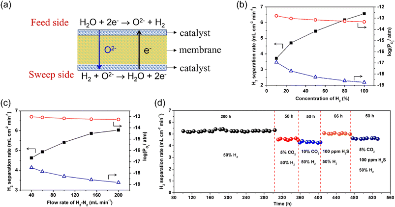 |
| | Fig. 10 Hydrogen production from the WSR with low concentration hydrogen as sweep gas in the MEOC membrane reactor. (a) Schematic, (b and c) dependence of the H2 production rate and oxygen partial pressure of both sides of the membrane reactor on the H2 concentration (b) and H2–N2 mixture flow rate (c) on the sweep side, and (d) long-term operation of the membrane reactor under various conditions. Reproduced with permission from ref. 85. Copyright @ 2018, American Institute of Chemical Engineers. | |
To increase the stability of perovskite-based MOEC membrane materials, Jia et al.82 developed a Ce0.9Gd0.1O3−δ(CGO)-enhanced triple-conducting (H+/O2−/e−) membrane reactor for coupling WSR with low concentration hydrogen oxidation, as shown in Fig. 11a. Both the H2 production rate and CO2 tolerance were improved with the doping of CGO phase into the Sr-based dual-phase membrane. The H2 production rate was 0.54 mL cm−2 min−1 at 940 °C, which was 1.5 times higher than that of the undoped SrCe0.95Fe0.05O3−δ–SrFe0.95Ce0.05O3−δ (SCF-SFC) membrane reactor due to the in situ oxygen removal ability through the doped-CGO phase promoting the WSR for hydrogen production (Fig. 11b). A stable H2 production rate of 0.33 mL cm−2 min−1 was achieved for ∼30 h at 900 °C under a CO2-containing atmosphere with the CGO-doped triple-conducting membrane reactor.
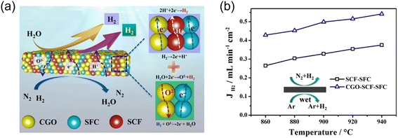 |
| | Fig. 11 Hydrogen production from the WSR with low concentration hydrogen as sweep gas in the triple-conducting membrane reactor. (a) Schematic and (b) H2 production rate of SCF-SFC and CGO-SCF-SFC membrane reactors as a function of temperature. Reproduced with permission from ref. 82. Copyright @ 2020, Elsevier B.V. All rights reserved. | |
SrTiO3-based perovskite, showing both good electronic conductivity and chemical stability under reducing atmospheres, was used to prepare a dual-phase membrane reactor for hydrogen production/separation. For example, Jia et al.84 reported a 60 mol% Ce0.9Pr0.1O2−δ-40 mol% Pr0.1Sr0.9Mg0.1Ti0.9O3−δ (CPO-PSM-Ti) dual-phase MOEC membrane reactor for H2 production from water splitting. The H2 production rate increased from 0.36 to 0.52 mL cm−2 min−1 by increasing the temperature from 860 °C to 940 °C. The CPO-PSM-Ti membrane reactor showed good stability during 180 h operation at 900 °C, indicating the robust stability of the SrTiO3-based perovskite material in a reducing atmosphere.
3.3 Syngas as the sweep gas
When syngas is used to substitute hydrogen as the sweep gas, the hydrogen production rate via WSR on the feed side will decrease due to the slower oxidation reaction kinetics of CO than H2. In addition, the produced CO2 by CO oxidation may occupy the active sites of the catalyst. For example, Li et al.86 studied the A-site deficiency and Ce-doped BaFeO3−δ (Ba0.95Ce0.05Fe0.95O3−δ, BCF)-based perovskite membrane reactor with loaded Ru/SDC catalyst for coupling hydrogen production with H2 and/or syngas oxidation. They found that the hydrogen production rate increased from 4.1 to 11.1 mL cm−2 min−1 with the H2 concentration on the sweep side increasing from 10% to 100% in an H2–He mixture. When using syngas (H2/CO = 1) as the sweep gas, a hydrogen production rate of 7.0 mL cm−2 min−1 was obtained on the feed side, which lower than the value of 8.1 mL cm−2 min−1 with 40% H2–He as the sweep gas. As shown in Fig. 12a and b, the hydrogen production rate increased with an increase in the syngas flow rate, while the CO conversion significantly decreased with an increase in the syngas flow rate. At a certain flow rate of syngas, the molar ratio of H2/CO showed little effect on the H2 production rate, but the CO conversion slightly increased with an increase in the H2/CO ratio. It should be noted that the oxygen partial pressures of both sides of the MOEC membrane reactor increased with an increase in temperature for both H2 and syngas as the sweep gas, as shown in Fig. 12c, which resulted in a decrease in the oxygen partial pressure gradient across the membrane. Alternatively, the water splitting and oxidation reactions, as well as the ambipolar diffusion of ions and electrons are all thermally activated. Thus, the overall influence of temperature on the hydrogen production rate is determined by these two factors. As shown in Fig. 12d, the hydrogen production rate increases with temperature, suggesting that the positive influence induced by an increase in temperature is stronger than its negative influence for hydrogen production in MOEC membrane reactors.
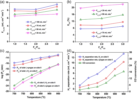 |
| | Fig. 12 Effect of the molar ratio of H2/CO on the H2 production rate (a) and CO conversion (b) at different flow rates at 900 °C with BCF-based MOEC membrane reactor. Relationship between temperature and corresponding oxygen partial pressure for both sides of the membrane reactor (c) and H2 production rate and CO conversion (d). Reproduced with permission from ref. 86. Copyright @ 2016, American Institute of Chemical Engineers. | |
To improve the permeation performance and long-term stability of MOEC membrane reactors, He et al.87 developed an interface-reaction-induced reassembly method to fabricate a three-layered MOEC membrane reactor for coupling H2 production with water splitting and coke oven gas (COG) oxidation reactions. As shown in Fig. 13a, the SrFeO3 grains are etched by Al2O3 through interface reactions of SrFeO3−δ + Al2O3 = SrAl2−xFexO4 + SrAl12−yFeyO19 at high temperatures. The local temperature was increased by the heat released via the above-mentioned reaction, which drive the reassembly of the surface-isolated Ce0.90Gd0.10O3−δ (CGO) grains into a dense layer, with a thickness of ∼2.5 μm. The thin CGO dense layer was well rooted in the intermediate layer, leading to strong adhesion. An H2 production rate of 1.84 mL cm−2 min−1 was achieved at 925 °C with 50%H2-COG as the sweep gas. The fabricated membrane reactor with a thin CGO dense layer showed very long durability (>1000 h) in harsh atmospheres (e.g. H2O, CH4, H2, CO2 and H2S), as shown in Fig. 13b and c.
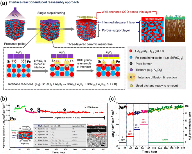 |
| | Fig. 13 (a) Schematic of the fabrication of a multilayered ceramic membrane with an ionic conducting dense layer via interface-reaction-induced reassembly. (b and c) Stability test of the prepared membrane reactor. (b) Illustration of >1000 h long-term stability under six different conditions and (c) H2S concentration in a simulated COG stream on H2 production rate from the WS reaction at 925 °C. Reproduced with permission from ref. 87. Copyright @ 2022, Wile-VCH GmbH. | |
Integrated gasification combined cycle (IGCC) with CO2 capture has great potential to mitigate greenhouse gas emission.96–98 However, the CO2 capture process results in a huge reduction in efficiency if a water gas shift (WGS) reactor is used with absorption-based CO2 capture technologies.99,100 Cai et al.73 and Wu et al.101 proposed the concept of integrating IGCC with an MOEC membrane reactor, as shown in Fig. 14a and b. The syngas from the gasifier and steam are fed to the sweep side and feed side, respectively of the MOEC membrane reactor. On the feed side, the produced H2 and unreacted H2O will flow to the power generation unit. Simultaneously, on the sweep side, a high concentration CO2 stream produced by the full oxidation of the syngas is ready for capture and storage. In their study, an H2 production rate of ∼17.5 mL cm−2 min−1 was obtained at 950 °C with syngas (H2/CO = 1) as the sweep gas in the SDC-SSCF membrane reactor loaded with an Ni/SDC catalyst. In addition, the MOEC membrane reactor exhibited strong stability during approximately 560 h operation at 900 °C in harsh conditions (e.g. 1000 ppm H2S, 20% CO2) (Fig. 14c and d).
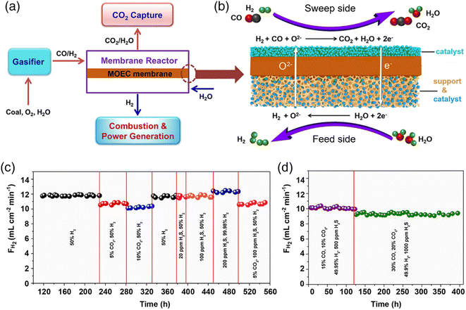 |
| | Fig. 14 Schematic of the IGCC-MOEC process and stability test. (a) Illustration of the IGCC-MOEC process. (b) Coupling H2 production, syngas oxidation, and CO2 capture in an MEOC membrane reactor. (c and d) H2 production rates during the long-term stability tests under various atmospheres at 900 °C. Reproduced with permission from ref. 73. Copyright @ 2020, American Institute of Chemical Engineers. | |
CO can also be used as the sweep gas in MOEC membrane reactors to reduce the oxygen partial pressure on the sweep side.94,102,103 For example, Xu et al.80 prepared an MOEC membrane reactor with a Ce0.85Pr0.15O2−δ–Pr0.6Sr0.4Fe0.9Al0.1O3−δ (CP-PSFA) membrane for coupling hydrogen production with CO oxidation. A hydrogen production rate of 0.99 mL cm−2 min−1 was obtained at 925 °C without a catalyst. The surface modification promoted the performance of the membrane reactor owing to the increase in the three-phase boundary for both water splitting and CO oxidation reactions, as shown in Fig. 15a. Su et al.79 designed a porous Ce0.85Pr0.15O2−δ (CP) layer coated on both sides of a CP-PSFA dual-phase membrane. An Ni-based catalyst was used to catalyze the surface reaction on both sides. As shown in Fig. 15b, the hydrogen production rate reached 1.79 mL cm−2 min−1 at 925 °C with a 1 mm thick membrane, which increased by 64% compared with the unmodified membrane reactor. In addition, the surface modification could also protect the membrane due to both its high reduction resistance and water vapor corrosion resistance, which improved the H2 production stability of the membrane reactor, as shown in Fig. 15c.
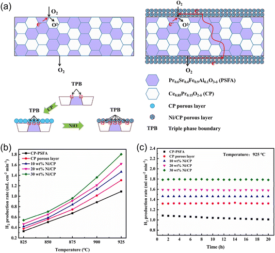 |
| | Fig. 15 (a) Schematic diagram of MOEC membrane for oxygen permeation with/without surface modification. (b) Temperature dependence of the H2 production rate of the MOEC membrane reactor. (c) Stability test of the MOEC membrane reactor at 925 °C. Reproduced with permission from ref. 79. Copyright @ 2022, Elsevier Ltd and Techna Group S.r.l. All rights reserved. | |
3.4 Methane as the sweep gas
3.4.1 Hydrogen production with partial oxidation of methane.
As introduced in the previous section, methane (or natural gas) is the main raw source for hydrogen production in industry, which is also one of the main sources of greenhouse gas emissions. Compared with the traditional SMR process, CO-free high-purity H2 and syngas with an H2/CO ratio of 2 can be obtained simultaneously on the feed side and sweep side, respectively, by MOEC membrane reactors.89 However, the hydrogen production rate on the feed side with methane as the sweep gas (0.3 mL cm−2 min−1 @ 900 °C) is lower than that with hydrogen as the sweep gas (6 mL cm−2 min−1 @ 900 °C) because hydrogen is more reactive than methane and the methane reforming reaction is more catalyst dependent.69
Generally, Co- and/or Fe-based membrane materials cannot work steadily under reducing atmospheres due to the deep-reduction of the Co and Fe ions, respectively.104–106 He et al.89 reported the fabrication of a Co- and Fe-free BaMg0.1Zr0.05Ti0.85O3−δ (BMZ-Ti) membrane reactor for coupling WSR for hydrogen production with methane reforming for syngas production, as shown in Fig. 16a and b. The developed membrane reactor showed robust chemical stability in a reducing atmosphere and H2 production rates of 0.21 and 0.8 mL cm−2 min−1 were obtained at 900 °C and 990 °C, respectively (Fig. 16c). The BMZ-Ti-based MOEC membrane reactor exhibited good stability at 960 °C for 100 h with an H2 production rate of ∼0.62 mL cm−2 min−1, as shown in Fig. 16d.
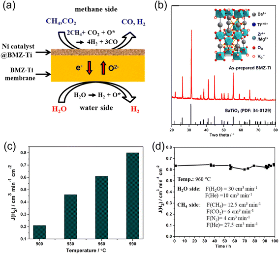 |
| | Fig. 16 Hydrogen production from WSR with partial oxidation of methane (POM) reaction on the sweep side with MOEC membrane reactor. (a) Schematic illustration, (b) XRD of BMZ-Ti membrane, (c) H2 production rate as a function of temperature and (d) stability test of the BZM-Ti membrane reactor at 960 °C. Reproduced with permission from ref. 89. Copyright @ 2021, the American Chemical Society. | |
To increase the methane conversion, Markov et al.90 adopted a tubular La0.5Sr0.5FeO3−δ (LSF)-based membrane reactor loaded with a 10%Ni/Al2O3 catalyst, with an effective surface area of more than 10 cm2, coupling WSR with POM reaction. A hydrogen production rate of ∼2 mL cm−2 min−1 was achieved at 900 °C with a CH4 conversion of 99% and CO selectivity of around 96%. The tubular membrane reactor could run stably for over 300 h.
The fluorite-type oxides (doped CeO2) have fast O2− mobility and good chemical stability, while the electronic conductivity of these oxides is low. Thus, to increase the H2 production rate, Fang et al.83 applied a mixed ionic-electronic conducting (MIEC) and ionic conducting (IC) composite dual-phase membrane reactor for coupling WSR for H2 production with the POM reaction for syngas production. A sandwich-like symmetrical configuration with a thin dense layer and two porous support layers was prepared, as shown in Fig. 17a. The Ni-based catalyst was impregnated into the support layer to increase the triple-phase boundary for water splitting and POM reactions (Fig. 17b and c). The H2 production rate of 11.7 mL cm−2 min−1 was obtained at 900 °C on the feed side. In addition, the membrane reactor could regenerate the deactivated catalyst in situ by H2O, as shown in Fig. 17d.
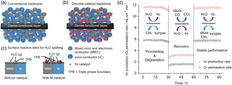 |
| | Fig. 17 Schematic diagram of (a) conventional blank backbone with a random mixture of an MIEC and IC material, (b) Ni-catalyst-impregnated MIEC/IC composite backbone, and (c) activity enhancement of the Ni-filtrated backbone for WS. (d) H2 production rate as a function of time through the Ni-infiltrated SDC-SSAF symmetrical dual-phase membrane reactor. Feed side: H2O = 50 mL min−1 (balanced by 50 mL min−1 N2) and sweep side: pure CH4 = 5.84 mL min−1, dilute CO = 3 mL min−1 CO + 20 mL min−1 He, dilute CH4 = 5 mL min−1 CH4 + 5 mL min−1 He. Temperature: 900 °C. Reproduced with permission from ref. 83. Copyright @ 2016, WILEY-VCH Verlag GmbH & Co. KGaA, Weinheim. | |
Son et al.72 reported the coupling of the POM reaction with water splitting at intermediate temperature (≤800 °C). As shown in Fig. 18a, a Ruddlesden–Popper oxide Pr2NiO4+δ (PNO) was used as the coating layer to catalyze water splitting on the feed side. Ni–La0.3Sr0.7TiO3−δ–Ce0.9Gd0.1O2−δ (Ni-LST-GDC) was coated on the sweep side as the POM catalyst. The Ce0.8Sm0.2O2−δ/SrFe0.75Mo0.25O3−δ (SDC/SFM, 70![[thin space (1/6-em)]](https://www.rsc.org/images/entities/char_2009.gif) :
:![[thin space (1/6-em)]](https://www.rsc.org/images/entities/char_2009.gif) 30 in volume) dual-phase material was used as the MOEC membrane. The H2 production rate of 4.6 mL cm−2 min−1 on the feed side and the syngas production rate of 14 mL cm−2 min−1 on the sweep side were obtained at 800 °C (Fig. 18b). They also found that the measured H2 production rate was much less than that calculated using the Wagner equation, as shown in Fig. 18c, which indicates that the surface reactions on both sides of the MOEC membrane reactor play an important role when the membrane thickness is less than 300 μm. This membrane reactor showed good stability at both 750 °C and 800 °C. However, the hydrogen production rate constantly decreased at 700 °C due to coking, as shown in Fig. 18d.
30 in volume) dual-phase material was used as the MOEC membrane. The H2 production rate of 4.6 mL cm−2 min−1 on the feed side and the syngas production rate of 14 mL cm−2 min−1 on the sweep side were obtained at 800 °C (Fig. 18b). They also found that the measured H2 production rate was much less than that calculated using the Wagner equation, as shown in Fig. 18c, which indicates that the surface reactions on both sides of the MOEC membrane reactor play an important role when the membrane thickness is less than 300 μm. This membrane reactor showed good stability at both 750 °C and 800 °C. However, the hydrogen production rate constantly decreased at 700 °C due to coking, as shown in Fig. 18d.
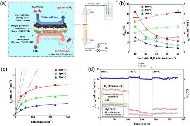 |
| | Fig. 18 Hydrogen production from partial oxidation of methane (POM) reaction in MOEC membrane reactor. (a) Schematic illustration, (b) H2O conversion and H2 production rate as a function of H2O inlet on feed side, (c) oxygen permeation flux as a function of membrane thickness, and (d) time dependence of H2 production rate from water splitting and syngas production rate from POM reaction in the temperature range of 800 °C to 700 °C. Reproduced with permission from ref. 72. Copyright @ 2023, Elsevier B.V. All rights reserved. | |
3.4.2 Hydrogen production with oxidative coupling of methane.
The production of C2 through the oxidative coupling of the methane (OCM) reaction is considered promising technology given that no intermediate step is needed.107,108 To mitigate the deep oxidation of the C2 products, one way is to use soft oxidants, such as CO2 (ref. 109 and 110) and N2O (ref. 111) instead of O2. In addition, MOEC membranes have also been used for coupling O2 separation from air with OCM reaction, where the O2 can be fed in a controlled way, resulting in a higher C2 yield.112
If H2O is used as the oxygen source on the feed side in an MOEC membrane reactor for the OCM reaction, pure H2 and C2 products can be obtained on the feed side and sweep side, respectively, as shown in Fig. 19a. Cao et al.81 first demonstrated this concept using a Ba0.5Sr0.5Co0.8Fe0.2O3−δ (BSCF)-based membrane reactor with a loading of 2 wt% Mn-5 wt% Na2WO4/SiO2 catalyst. As shown in Fig. 19b and c, a CH4 conversion of 26% and C2 product yield of 6.5% were obtained at 950 °C in the membrane reactor, which are much higher than that in the fixed bed reactor. With an increase in temperature from 850 °C to 950 °C, the CH4 conversion and C2 yield in the membrane reactor increased from 3.7% and 3.1% to 26% and 6.5%, respectively. As shown in Fig. 19d, the H2 production rate on the feed side increased from 0.4 to 3.3 mL cm−2 min−1 by increasing temperature from 850 °C to 950 °C.
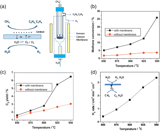 |
| | Fig. 19 Hydrogen production from oxidative methane coupling and water splitting in MOEC membrane reactor. (a) Schematic illustration, (b) CH4 conversion with and without membrane as a function of temperature, (c) C2 yield with and without membrane as a function of temperature, and (d) hydrogen production rate on the feed side as a function of temperature. Reproduced with permission from ref. 81. Copyright @ 2011, Elsevier B.V. All rights reserved. | |
3.5 Ethane as the sweep gas
As introduced in section 2.4, the use of an MOEC membrane reactor for the alkane dehydrogenation process is also promising technology to produce alkene due to the fact that the by-product H2 can react with the permeated oxygen. Furthermore, pure H2 can be obtained on the feed side by WSR. For example, Jiang et al.104 combined water splitting and ethane dehydrogenation (ODH) reactions in a BaCoxFeyZr1−x−yO3−δ (BCFZ) hollow-fiber membrane reactor at moderate temperatures (700–800 °C), as shown in Fig. 20a. After steam condensation, high-purity H2 and ethylene could be achieved on the feed side and sweep side, respectively. The H2 production rate increased from 0.1 to 0.4 mL cm−2 min−1 by increasing the temperature from 700 °C to 800 °C with 7.6% C2H6 as the sweep gas. By increasing the C2H6 concentration to 20%, the H2 production rate reached 1.2 mL cm−2 min−1 at 800 °C. The performance of the BCFZ-based membrane reactor was stable during the 100 h operation. However, a surface-eroded layer with a thickness of ∼10 μm was formed due to the reduction of Co cations, as shown in Fig. 20b. Thus, Schucker et al.92 prepared a Co-free and BaFe0.9Zr0.1O3−δ (BFZ)-based MOEC membrane reactor for coupling water splitting with ODH reactions. Consequently, an H2 production rate of 5.9 mL cm−2 min−1 was achieved at 900 °C with 10% C2H6 as the sweep gas, but no stability test was reported in their study.
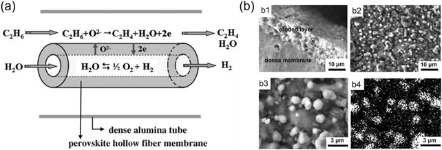 |
| | Fig. 20 (a) Water splitting coupled with ethane dehydrogenation in MOEC membrane reactor. (b) SEM images of the ethane side of the BCFZ hollow-fiber membrane after 100 h operation. b1) Cross-section, b2) and b3) top views, and b4) corresponding elemental distribution image of cobalt. Reproduced with permission from ref. 104. Copyright @ 2010 WILEY-VCH, Verlag GmbH & Co. KGaA, Weinheim. | |
3.6 Ethanol as the sweep gas
Ethanol is a non-toxic and easy to store and transport energy source, which is also easily produced via agricultural waste or biomass. Furthermore, 6 moles of H2 can be obtained by steam reforming per mole of ethanol (eqn (8)).| |  | (8) |
Therefore, H2 production via the steam reforming of ethanol (SRE) has been widely studied in recent years.28,113,114 However, in a traditional fixed bed reactor, the H2-rich stream needs to be purified by several steps to obtain high-purity H2 (at least CO-free) for further utilization (such as PEM fuel cells). Obviously, membrane reactor technology shows good potential for H2 production via the SRE process.10 Park et al.94 first attempted to couple the oxidative steaming reforming of ethanol (OSRE) to produce hydrogen with the oxygen permeation process in an La0.7Sr0.3Cu0.2Fe0.8O3−δ (LSCuF)-based MOEC membrane reactor. The H2 production rate of 0.12 mL cm−2 min−1 with an ethanol conversion of 58.7% was obtained at 700 °C. Then, Zhu et al.93 optimized the OSRE process with H2O as both the H2 source from water splitting and oxygen source for OSRE reaction, as shown in Fig. 21a. An SrCo0.4Fe0.5Zr0.1O3−δ (SCFZ) tubular membrane reactor loaded with an Ni/Al2O3 catalyst was applied to realize this concept. Consequently, an ethanol conversion of 100% was achieved in their study, and the conversion was independent of the H2O/ethanol molar ratio. They also found that the hydrogen production rate increased with an increase in the H2O/ethanol ratio, while high H2O/ethanol ratios decreased the H2O conversion and increased the energy consumption. Thus, the optimized H2O/ethanol ratio in the OSRE process was 4.8 at 900 °C. The H2 production rate from WSR increased from 1.3 to 3.4 mL cm−2 min−1 by increasing the temperature from 700 °C to 900 °C. At 900 °C, a total H2 production rate of 56.7 mL cm−2 min−1 was achieved at the ethanol side (sweep side). In the MOEC membrane reactor coupling the OSRE with water splitting process, the WSR is the key rate-limiting step. For example, at 750 °C, the H2 production rates of 6.8 and 1.8 mL cm−2 min−1 were obtained on the sweep side (OSRE reaction) and the feed side (WSR), respectively (Fig. 21b). Therefore, high-activity catalysts for WSR should be developed in further studies.
 |
| | Fig. 21 Membrane reactor for coupling water splitting and oxidative steam reforming of ethanol. (a) Schematic diagram and (b) stability test at 750 °C. Shell side (sweep side): ethanol partial pressure = 0.06 atm, ethanol flow rate = 0.9 mL min−1, n(H2O)/n(ethanol) = 4.8 and tube side (feed side): H2O partial pressure = 0.6 atm, N2 flow rate = 100 mL min−1. Reproduced with permission from ref. 93. Copyright @ 2012, the Royal Society of Chemistry. | |
4 MOCC membrane reactors
4.1 Chemistry of MOCC membrane reactor for hydrogen production
Recently, Lin's group115–119 and Huang's group23,120–122 proposed a type of ceramic-carbonate dual-phase MOCC membrane for high-temperature CO2 capture. The theoretical CO2 selectivity to all other gases is infinite in the MOCC membrane in the temperature range of 500–900 °C. A typical ceramic-carbonate membrane is composed of an O2− conductor and a CO32− conductor. As shown in Fig. 21, CO2 is transported through the membrane in the form of CO32−, and thus only CO2 can permeate the membrane. On the feed side of the membrane surface, CO32− is formed by the reaction between CO2 and O2−, and then the formed CO32− diffuses to the sweep side under the chemical potential gradient of CO2. The opposite flow of O2− (relative to CO32−) acts as charge compensation to make the membrane electrically neutral. When an MOCC membrane reactor is applied for H2 production, as shown in Fig. 22, both H2 and CO2 should be the products on the feed side. The in situ removal of CO2 from the reaction spot can break the thermodynamic equilibrium limitation, resulting in a significant improvement in the reaction conversion. An H2-enriched stream will be obtained on the feed side. However, pure H2 is difficult to achieve through the MOCC membrane reactor, given that the unreacted reactants (e.g. CO and CH4) as well as the produced CO2 are difficult to remove completely by the MOCC membrane. However, the advantages of the MOCC membrane reactor are as follows: (1) it retains H2 at high pressure, maximizing the efficiency of the combustion turbine; (2) it has the potential to achieve 100% H2 recovery, and (3) a pure CO2 stream can be achieved if vacuum is applied on the sweep side.123 The H2 production rate through different MOCC membrane reactors is summarized in Table 3.
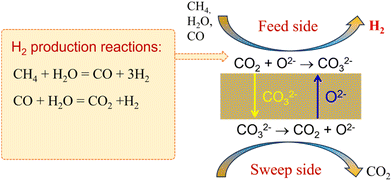 |
| | Fig. 22 Working principle of MOCC membrane reactor for coupling hydrogen production and CO2 capture. | |
Table 3 Summary of hydrogen production with MOCC membrane reactors
| Membrane |
Catalyst |
Thickness(μm) |
Feed gas/sweep gas |
T (°C) |
H2 production rate(mL cm−2 min−1) |
Stability |
Ref. |
| SDC: Sm0.2Ce0.8O2−δ, MC: 42.5%Li2CO3-32.5%Na2CO3-25%K2CO3, and BYS: Bi1.5Y0.3Sm0.2O3−δ. |
| SDC-MC |
— |
1500 |
Wet-49.5%CO-36%CO2-10%H2-4.5%N2 (H2O:CO = 3)/He |
800 |
1.4 |
120 h at 900 °C |
123
|
| 900 |
2.5 |
| BYS/SDC-SDC/MC |
Ni based (HiFUEL R110) |
150 |
75%H2O–CH4/He |
900 |
13.5 |
100 h |
124
|
4.2 Hydrogen production from WGS reaction
In the traditional IGCC process, the produced syngas should be further treated with a two-step WGS process, which converts CO to H2 and CO2. A process for the separation of H2 and CO2 is required to obtain high-purity H2 and to store CO2. Given that WGS is an exothermic reaction, it should operate at low temperatures (200–250 °C) to achieve a high CO conversion. However, the low temperature operation of the WGS reaction has a cooling penalty on the produced syngas, which is an energy-intense process. Thus, a high-temperature WGS reaction in an H2-permselective membrane reactor was proposed by the National Energy Technology Laboratory (NETL) in the US.125 Besides the in situ removal of H2 from an H2–CO2 mixture, CO2 separation is considered another promising strategy to enhance the WGS reaction performance, which has the potential to obtain high H2 recovery and retain the H2 at a high pressure.126–128 However, the development of a membrane that can permeate CO2 but retain H2 at high temperatures is a great challenge.129–131
Dong et al.123 first proposed a single MOCC membrane reactor for coupling H2 production via the WGS reaction with CO2 capture, as shown in Fig. 23a. The in situ removal of the by-product CO2 from the reaction zone broke the thermodynamic equilibrium limitation and shifted the CO conversion reaction to produce H2. Thus, the exothermic WGS reaction in the MOCC membrane reactor could be carried out at relatively high temperatures, such as 700–900 °C. Particularly, the high temperature operation could avoid the application of a catalyst for the WGS reaction, thus saving capital costs and simplifying the design of the membrane reactor. An Sm0.2Ce0.8O1.9–(Li-Na-K)2CO3 dual-phase MOCC membrane was used as the catalyst-free tubular membrane reactor.
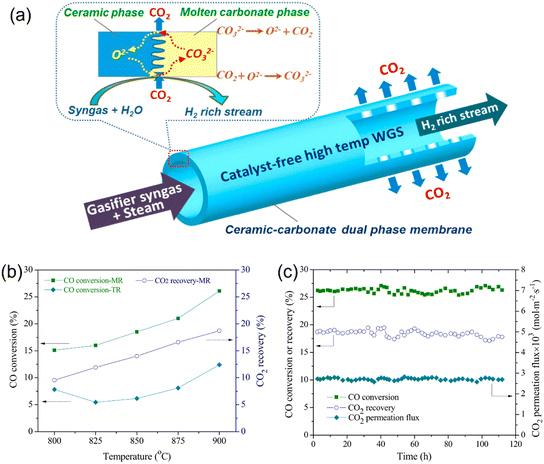 |
| | Fig. 23 MOCC membrane reactor for coupling WGS reaction and CO2 capture. (a) Schematic diagram, (b) performance of membrane reactor and fixed bed reactor as a function of temperature, and (c) long-term stability of membrane reactor at 900 °C. Reproduced with permission from ref. 123. Copyright @ 2016, Elsevier B.V. All rights reserved. | |
The CO2 permeation flux, temperature, syngas flow rate and H2O/CO ratio are the four main factors that can influence the H2 production rate by the MOCC membrane reactor. As shown in Fig. 23b, the CO conversion and CO2 recovery increased from 15.1% and 9.6% to 26.1% and 18.7% by increasing temperature from 800 °C to 900 °C in an MOCC membrane reactor, respectively.123 The H2 production rates of 1.4 and 2.5 mL min−1 were obtained at 800 °C and 900 °C, respectively. The membrane reactor exhibited a much higher CO conversion than the traditional fixed bed reactor. An increase in the H2O/CO ratio in the MOCC membrane reactor resulted in an increase in CO conversion, but slightly reduced the CO2 recovery. The maximum H2 production rate of ∼3.0 mL min−1 was achieved at 900 °C with the syngas flow rate of 30 mL min−1. The MOCC membrane reactor showed good chemical and thermal stability during the WGS reaction process at 900 °C for 120 h, as shown in Fig. 23c.
Meng et al.132 developed a one-dimensional model (1D model) for the simulation of the WGS reaction in an MOCC membrane reactor. Both the mass and heat transport were considered in their modeling. In a traditional fixed bed reactor, increasing the pressure is usually done to speed up the reaction rate, whereas for the WGS reaction, it does not increase the CO conversion. One advantage of the MOCC membrane reactor for coupling the WGS reaction with CO2 capture is that the CO conversion can be significantly enhanced by increasing the feed pressure, given that the CO2 permeation process is driven by the CO2 partial pressure gradient across the membrane. As shown in Fig. 24a, the CO conversion was maintained at 33.8% at 900 °C with an H2O/CO ratio of 4 by increasing the feed pressure from 1 to 30 bar in the fixed bed reactor, while it increased from 54.9% to ∼98% in the MOCC membrane reactor. When the feed pressure was higher than 15 bar, the CO conversion was higher than 95% in the MOCC membrane reactor. In a traditional fixed bed reactor, the CO conversion decreases an increase in temperature due to the exothermic nature of the WGS reaction. As shown in Fig. 24b, at 30 bar, the CO conversion of 33.6% was obtained at 900 °C with the fixed bed reactor, while the CO conversion was higher than 98% in the temperature range of 800 °C to 900 °C in the MOCC membrane reactor due to its in situ CO2 removal ability. The CO conversion of 95.4% and CO2 recovery of 94.0% were obtained in the MOCC membrane reactor with oxygen-blown gasifier syngas (37.2% H2, 46.6% CO, 13.3% CO2, 2.5% N2 and 0.0% other gases) as the feed gas. High-pressure H2 could be obtained on the feed side with an H2 purity of 90.9% due to the presence of unreacted CO (2.4%), unrecovered CO2 (3.8%) and N2 (2.9%), as shown in Fig. 24c, while pure CO2 could be obtained on the sweep side.
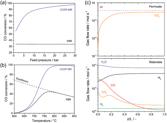 |
| | Fig. 24 Modeling study of coupling WGS reaction with CO2 capture. (a) Effect of feed pressure on the CO conversion in fixed bed reactor and MOCC membrane reactor at 900 °C with H2O/CO ratio of 4. (b) CO conversion as a function of temperature in fixed bed reactor and MOCC membrane reactor. (c) Profile of gas flow rate in MOCC membrane reactor at 800 °C with H2O/CO ratio of 4. Permeate: sweep side. Retentate: feed side. Reproduced with permission from ref. 132. Copyright @ 2021, the American Chemical Society. | |
4.3 Hydrogen production from steam methane reforming
Besides H2 permselective membrane reactors, CO2-permselective membrane reactors are also a promising route to increase the H2 production rate in SMR. Wu et al.124 first demonstrated an MOCC membrane reactor for coupling the SMR reaction with CO2 capture, as shown in Fig. 25a. A two-layer asymmetric tubular membrane was fabricated with BYS-SDC as the porous support layer and SDC-MC as the dense layer. The CH4 conversion in the MOCC membrane reactor was slightly higher than that in the fixed bed reactor, as shown in Fig. 25b, due to the high H2O/CH4 ratio and high operation temperatures (700–900 °C). However, the H2 yield of 90% was obtained at 900 °C in the membrane reactor, which is much higher than that in the fixed bed reactor (81%). Meanwhile, the H2 concentration increased from 76% to 88% and the CO concentration decreased from 18% to 9% in the membrane reactor (Fig. 25c), indicating that the MOCC membrane reactor can promote the WGS reaction through in situ CO2 removal.
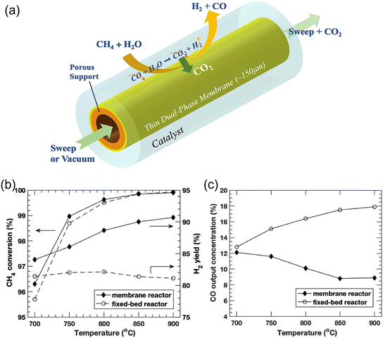 |
| | Fig. 25 MOCC membrane reactor for coupling the SRM reaction and CO2 capture. (a) Schematic, (b) CH4 conversion and H2 yield by the membrane reactor and fixed bed reactor as a function of temperature, and (c) CO concentration (dry-based) comparison of the membrane reactor and fixed bed reactor. Reproduced with permission from ref. 124. Copyright @ 2019, Elsevier B.V. All rights reserved. | |
High-pressure operation on the feed side will significantly improve the membrane reactor performance. However, there is no experimental report on the use of an MOCC membrane reactor in SMR reaction for H2 production at high pressures to date due to the fact that the sealant used in MOCC membrane reactors do not work at high pressures. Thus, Ovalle-Encinia et al.133 used a mathematical simulation method to study the effect of pressure on the H2 production performance by MOCC membrane reactors. They simulated the effects of Damköhler number (Da, the ratio of the SMR reaction rate to convective mass transport rate), permeation number (θ, the ratio of CO2 flux to the methane feed flow rate), feed pressure and sweep side conditions on the SMR performance of the MOCC membrane reactor. At low pressures, both the CO conversion and H2 yield increased by increasing the permeation number, θ, while the CH4 conversion was not affected by changing θ. The H2 concentration on the feed side can reach 96% with a CO2 recovery of 95%. At high pressures (e.g. 15 and 30 atm), the CH4 conversion is low at low θ due to the lower equilibrium conversion of the SMR reaction with an increase in pressure. However, the CH4 conversion increases with an increase in the θ value given that the in situ removal of CO2 promotes CH4 conversion. The CH4 conversion and H2 yield cannot reach 100% even at a high θ given the low thermodynamic equilibration constant and limited CO2 removal rate. Thus, to further improve the CH4 conversion and H2 yield, low pressure conditions are required on the sweep side. As shown in Fig. 26, with a low sweep side pressure (10−3 atm) and high feed side pressure (5 atm), essentially 100% CH4 conversion, 100% H2 yield and 100% CO2 recovery can be obtained in an MOCC membrane reactor with θ higher than 3 and Da higher than 10![[thin space (1/6-em)]](https://www.rsc.org/images/entities/char_2009.gif) 000 because the vacuum on the sweep side enables CO2 permeation even at a very low CO2 pressure on the feed side.
000 because the vacuum on the sweep side enables CO2 permeation even at a very low CO2 pressure on the feed side.
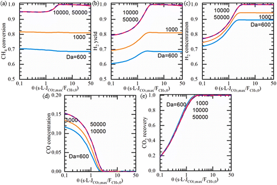 |
| | Fig. 26 Simulation results of (a) CH4 conversion, (b) H2 yield, (c) H2 concentration, (d) CO concentration, and (e) CO2 recovery, when 5 atm and 10−3 vacuum sweep are applied. At 800 °C, S/C = 3, sweep/feed flow rate ratio = 100. Dry-based molar concentration calculation. Reproduced with permission from ref. 133. Copyright @ 2021, Elsevier B.V. All rights reserved. | |
5 Conclusions and outlook
This review summarized the use of three types of ceramic-based dense membrane reactors for hydrogen production by methane reforming, water splitting, alkane dehydrogenation, water gas shift reaction and ammonia decomposition. The three types of ceramic-based membranes were classified based on their different conductivity properties including mixed proton and electron conductor (MPEC), mixed oxide-ion and electron conductor (MOEC), and mixed oxide-ion and carbonate-ion conductor (MOCC).
5.1 MPEC membrane reactors for hydrogen production
The activation energy of proton conducting is lower than that of the oxide-ion conductor, and thus theoretically a high H2 production rate should be achieved with MPEC membrane reactors even at low and medium temperatures. However, MPEC membrane reactors show relatively low hydrogen production rates (0.01–1 mL cm−2 min−1) and low H2 recovery. On the one hand, chemical reactions to consume the permeated H2 cannot be used given that H2 is the target product. On the other hand, high-pressure feed gas cannot be applied due to the problem of high-temperature sealing.
Thus far, only a few reports showed MPEC-based membrane reactors for H2 production due to their low H2 permeation flux and recovery. However, proton conductor-based electrolysis cells have been widely used for H2 production via water splitting.
5.2 MOEC membrane reactors for hydrogen production
Different from the other two types of membrane reactors, the H2 production in MOEC membrane reactors should be from WSR on the feed side. However, many reactions to consume oxygen can be applied on the sweep side to create a large oxygen partial pressure gradient. Furthermore, the diversification of reactions on the sweep side provides more possibilities to produce high-value chemicals, making MOEC membrane reactors more practical. Compared to MPEC membrane reactors, a higher H2 production rate can be achieved in MOEC membrane reactors due to their high mixed oxide-ionic and electronic conductivity and ability to couple with an oxidation reaction to consume oxygen, thus enhancing the water splitting rate.
The oxygen permeation performance and long-term stability are two core factors for MOEC membrane reactors. Perovskite and fluorite are the most popular MOEC membrane materials for oxygen separation from air. However, when MOEC membrane reactors are used for hydrogen production via water splitting, both sides of the membrane are in reducing atmospheres, rather than the traditional oxidation atmospheres. Thus, the chemical instability of single perovskites under reducing conditions hinders their utilization in MOEC membrane reactors. Alternatively, fluorites exhibit higher chemical stability and lower chemical expansion, but their electronic conductivity is negligible (especially ZrO2-based fluorites). Both metal-fluorite-based dual-phase membrane and perovskite-fluorite based dual-phase membrane materials have been widely studied for use in MOEC membrane reactors. Thus, the development of new multi-phase membrane materials and surface coating layers (catalysis and/or protection) should be two important directions to improve the permeation performance and long-term stability of MOEC membrane reactors.
5.3 MOCC membrane reactors for hydrogen production
MOCC membranes are a new type of high-temperature CO2 permselective membranes, which can be used for H2 production via chemical reactions with CO2 and H2 as the products. The in situ removal of by-product CO2 can shift the reactions toward H2 production. However, is difficult to achieve a pure H2 stream due to the thermodynamic limitation, and the produced CO2 cannot be completely removed by the MOCC membrane. On the one hand, it has the potential to maintain H2 at high pressure and achieve 100% H2 recovery on the feed side. On the other hand, a pure CO2 stream can be obtained on the sweep side.
Currently, only two chemical reactions (water gas shift and steam methane reforming) have been reported for H2 production in MOCC membrane reactors. The reported H2 production rate is low due to the relatively low CO2 permeation flux with an inert sweep gas in MOCC membrane reactors. Similar to MOEC membrane reactors, coupling chemical reactions that can consume permeated CO2 on the sweep side is a promising strategy to improve the H2 production rate. In addition, increasing the feed side pressure is another potential method to improve the H2 production and CO2 recovery performance, which can offer huge savings in energy consumption in the H2 production process with CO2 capture.
Data availability
No primary research results, software or code has been included and no new data were generated or analysed as part of this review.
Conflicts of interest
There are no conflicts to declare.
Acknowledgements
We thank for the financial support from the National Key R&D Program of China (2022YFB3805501), National Natural Science Foundation of China (22378380, 22178332), Natural Science Foundation of Liaoning Province (2023-MS-012), the Innovative Research Fund of DICP (DICP I202221) and Bolian Research Funds of Dalian Maritime University (3132024602).
References
- W. Wu, H. Zhai and E. Holubnyak, Technological evolution of large-scale blue hydrogen production toward the U.S. Hydrogen Energy Earthshot, Nat. Commun., 2024, 15, 5684 CrossRef CAS PubMed.
- P. Wang, J. Zheng, X. Xu, Y. Q. Zhang, Q. F. Shi, Y. Wan, S. Ramakrishna, J. Zhang, L. Zhu, T. Yokoshima, Y. Yamauchi and Y. Z. Long, Unlocking Efficient Hydrogen Production: Nucleophilic Oxidation Reactions Coupled with Water Splitting, Adv. Mater., 2024, 2404806 CrossRef CAS PubMed.
- Q. Liu, S. Du, T. Liu, L. Gong, Y. Wu, J. Lin, P. Yang, G. Huang, M. Li, Y. Wu, Y. Zhou, Y. Li, L. Tao and S. Wang, Efficient Low-temperature Hydrogen Production by Electrochemical-assisted Methanol Steam Reforming, Angew. Chem., Int. Ed., 2024, 63, e202315157 CrossRef CAS PubMed.
- G. S. Cassol, C. Shang, A. K. An, N. K. Khanzada, F. Ciucci, A. Manzotti, P. Westerhoff, Y. Song and L. Ling, Ultra-fast green hydrogen production from municipal wastewater by an integrated forward osmosis-alkaline water electrolysis system, Nat. Commun., 2024, 15, 2617 CrossRef CAS PubMed.
- L. Xie, L. Wang, X. Liu, J. Chen, X. Wen, W. Zhao, S. Liu and Q. Zhao, Flexible tungsten disulfide superstructure engineering for efficient alkaline hydrogen evolution in anion exchange membrane water electrolysers, Nat. Commun., 2024, 15, 5702 CrossRef CAS PubMed.
- H. Xie, Z. Zhao, T. Liu, Y. Wu, C. Lan, W. Jiang, L. Zhu, Y. Wang, D. Yang and Z. Shao, A membrane-based seawater electrolyser for hydrogen generation, Nature, 2022, 612, 673–678 CrossRef CAS PubMed.
- O. Massarweh, M. Al-khuzaei, M. Al-Shafi, Y. Bicer and A. S. Abushaikha, Blue hydrogen production from natural gas reservoirs: A review of application and feasibility, J. CO2 Util., 2023, 70, 102438 CrossRef CAS.
- I. Kountouris, R. Bramstoft, T. Madsen, J. Gea-Bermúdez, M. Münster and D. Keles, A unified European hydrogen infrastructure planning to support the rapid scale-up of hydrogen production, Nat. Commun., 2024, 15, 5517 CrossRef CAS PubMed.
- K. Jiang, Z. Liu, G. Zhang and W. Jin, A novel catalytic membrane reactor with homologous exsolution-based perovskite catalyst, J. Membr. Sci., 2020, 608, 118213 CrossRef CAS.
- A. Iulianelli and A. Basile, Hydrogen production from ethanol via inorganic membrane reactors technology: a review, Catal. Sci. Technol., 2011, 1, 366–379 RSC.
- M. A. Habib, A. Harale, S. Paglieri, F. S. Alrashed, A. Al-Sayoud, M. V. Rao, M. A. Nemitallah, S. Hossain, M. Hussien, A. Ali, M. A. Haque, A. Abuelyamen, M. R. Shakeel, E. M. A. Mokheimer and R. Ben-Mansour, Palladium-Alloy Membrane Reactors for Fuel Reforming and Hydrogen Production: A Review, Energy Fuels, 2021, 35, 5558–5593 CrossRef CAS.
- O. Jazani, J. Bennett and S. Liguori, Carbon-low, renewable hydrogen production from methanol steam reforming in membrane reactors – a review, Chem. Eng. Process., 2023, 189, 109382 CrossRef CAS.
- V. Cechetto, L. Di Felice and F. Gallucci, Advances and Perspectives of H2 Production from NH3 Decomposition in Membrane Reactors, Energy Fuels, 2023, 37, 10775–10798 CrossRef CAS PubMed.
- W.-H. Chen and C.-Y. Chen, Water gas shift reaction for hydrogen production and carbon dioxide capture: A review, Appl. Energy, 2020, 258, 114078 CrossRef CAS.
- T. Y. Amiri, K. Ghasemzageh and A. Iulianelli, Membrane reactors for sustainable hydrogen production through steam reforming of hydrocarbons: A review, Chem. Eng. Process., 2020, 157, 108148 CrossRef CAS.
- A. Fasolini, R. Mafessanti, S. Abate, P. Gramazio, J. De Maron, G. Centi and F. Basile, Integration of catalytic methane oxy-reforming and water gas shift membrane reactor for intensified pure hydrogen production and methanation suppression over Ce0.5Zr0.5O2 based catalysts, Catal. Today, 2023, 418, 114047 CrossRef CAS.
- H. Li, A. Caravella and H. Y. Xu, Recent progress in Pd-based composite membranes, J. Mater. Chem. A, 2016, 4, 14069–14094 RSC.
- Y. Escalante and A. M. Tarditi, Enhanced resistance of PdNiAu membranes under CO and H2S-containing streams, J. Membr. Sci., 2024, 705, 122905 CrossRef CAS.
- X. Tan, Z. Shen, A. Bokhari, W. Ali and N. Han, Effect of Co2O3 as sintering aid on perovskite BaCe0.8Y0.2O3-δ proton conductive membrane for hydrogen separation, Int. J. Hydrogen Energy, 2023, 48, 26551–26558 CrossRef CAS.
- X. Tan, Z. Shen, A. Bokhari, M. A. Qyyum and N. Han, Insights on perovskite-type proton conductive membranes for hydrogen permeation, Int. J. Hydrogen Energy, 2023, 48, 26541–26550 CrossRef CAS.
- L. Yang, Z. Cao, Y. Zhu, J. Wang, B. Pang, W. Zhang, L. Zhang, S. Hu, X. Zhu and W. Yang, Single- and dual-phase capillary membranes prepared through plastic extrusion method for oxygen permeation, Ceram. Int., 2021, 47, 18510–18516 CrossRef CAS.
- R. Kiebach, S. Pirou, L. Martinez Aguilera, A. B. Haugen, A. Kaiser, P. V. Hendriksen, M. Balaguer, J. García-Fayos, J. M. Serra, F. Schulze-Küppers, M. Christie, L. Fischer, W. A. Meulenberg and S. Baumann, A review on dual-phase oxygen transport membranes: from fundamentals to commercial deployment, J. Mater. Chem. A, 2022, 10, 2152–2195 RSC.
- P. Zhang, J. Tong, K. Huang, X. Zhu and W. Yang, The current status of high temperature electrochemistry-based CO2 transport membranes and reactors for direct CO2 capture and conversion, Prog. Energy Combust. Sci., 2021, 82, 100888 CrossRef.
- S. Wang, J. Tong, L. Cui, P. Zhang and F. Zhou, A layered perovskite La1.5Sr0.5NiO4±δ-molten carbonate dual-phase membrane for CO2 capture from simulated flue gas, J. Membr. Sci., 2022, 647, 120278 CrossRef CAS.
- G. Weng, K. Ouyang, X. Lin, J. Xue and H. Wang, Proton conducting membranes for hydrogen and ammonia production, React. Chem. Eng., 2021, 6, 1739–1770 RSC.
- S. Sun and K. Huang, Efficient and selective ethane-to-ethylene conversion assisted by a mixed proton and electron conducting membrane, J. Membr. Sci., 2020, 599, 117840 CrossRef CAS.
- Y. Matsumura and J. Tong, Methane Steam Reforming in Hydrogen-permeable Membrane Reactor for Pure Hydrogen Production, Top. Catal., 2008, 51, 123–132 CrossRef CAS.
- A. Basile, P. Pinacci, A. Iulianelli, M. Broglia, F. Drago, S. Liguori, T. Longo and V. Calabrò, Ethanol steam reforming reaction in a porous stainless steel supported palladium membrane reactor, Int. J. Hydrogen Energy, 2011, 36, 2029–2037 CrossRef CAS.
- A. Iulianelli, S. Liguori, Y. Huang and A. Basile, Model biogas steam reforming in a thin Pd-supported membrane reactor to generate clean hydrogen for fuel cells, J. Power Sources, 2015, 273, 25–32 CrossRef CAS.
- E. Mercadelli, A. Gondolini, D. Montaleone, P. Pinasco, S. Escolástico, J. M. Serra and A. Sanson, Production strategies of asymmetric BaCe0.65Zr0.20Y0.15O3-δ – Ce0.8Gd0.2O2-δ membrane for hydrogen separation, Int. J. Hydrogen Energy, 2020, 45, 7468–7478 CrossRef CAS.
- J. W. Phair and S. P. S. Badwal, Review of proton conductors for hydrogen separation, Ionics, 2006, 12, 103–115 CrossRef CAS.
- Z. Zhu, B. Liu, J. Shen, Y. Lou and Y. Ji, La2Ce2O7: A promising proton ceramic conductor in hydrogen economy, J. Alloys Compd., 2016, 659, 232–239 CrossRef CAS.
- H. Cheng, Rare Earth Tungstate: One Competitive Proton Conducting Material Used for Hydrogen Separation: A Review, Separations, 2023, 10, 317 CrossRef CAS.
- S. Cheng, X. Li, X. Huang, Y. Ling, S. Liu and T. Li, Hydrogen separation via proton conducting ceramic membranes: A review, Int. J. Hydrogen Energy, 2024, 70, 654–665 CrossRef CAS.
- H. Cheng, B. Meng, C. Li, X. Wang, X. Meng, J. Sunarso, X. Tan and S. Liu, Single-step synthesized dual-layer hollow fiber membrane reactor for on-site hydrogen production through ammonia decomposition, Int. J. Hydrogen Energy, 2020, 45, 7423–7432 CrossRef CAS.
- X. Xia, H. Zhou, Y. Zhang and H. Jiang, Innovative steam methane reforming for coproducing CO-free hydrogen and syngas in proton conducting membrane reactor, AIChE J., 2019, 65, e16740 CrossRef CAS.
- J. L. Li, H. Yoon and E. D. Wachsman, Carbon dioxide reforming of methane in a SrCe0.7Zr0.2Eu0.1O3-δ proton conducting membrane reactor, Int. J. Hydrogen Energy, 2012, 37, 19125–19132 CrossRef CAS.
- J. Li, H. Yoon, T.-K. Oh and E. D. Wachsman, SrCe0.7Zr0.2Eu0.1O3-based hydrogen transport water gas shift reactor, Int. J. Hydrogen Energy, 2012, 37, 16006–16012 CrossRef CAS.
- M. Sakbodin, Y. Wu, S. C. Oh, E. D. Wachsman and D. Liu, Hydrogen-Permeable Tubular Membrane Reactor: Promoting Conversion and Product Selectivity for Non-Oxidative Activation of Methane over an Fe©SiO2 Catalyst, Angew. Chem., Int. Ed., 2016, 55, 16149–16152 CrossRef CAS PubMed.
- H.-M. Kim, C. H. Jeong, B.-S. Cheon, S. S. Negi, W. Won and D.-W. Jeong, Improving the Performance of a Co-CeO2 Catalyst for Hydrogen Production via Water Gas Shift Reaction by Addition of Transition Metal Oxides, Energy Fuels, 2024, 38, 4743–4751 CrossRef CAS.
- S. Zhao, R. Zhang, H. Huang, C. Sun, H. Jin, K. Zhao and B. Bai, Intrapore water–gas shift reaction inhibits coal gasification in supercritical water, Chem. Eng. Sci., 2024, 289, 119843 CrossRef CAS.
- T. Shao, L. Cao, L. Li, Y. Su, B. Hou, J. Lin and X. Wang, A noble-metal-free catalyst with MoC nanorod for low-temperature water gas shift reaction, Chem. Eng. J., 2024, 485, 149967 CrossRef CAS.
- Y.-L. Lee, K.-J. Kim, G.-R. Hong and H.-S. Roh, Target-oriented water–gas shift reactions with customized reaction conditions and catalysts, Chem. Eng. J., 2023, 458, 141422 CrossRef CAS.
- J. Li, H. Yoon, T.-K. Oh and E. D. Wachsman, High temperature SrCe0.9Eu0.1O3−δ proton conducting membrane reactor for H2 production using the water–gas shift reaction, Appl. Catal., B, 2009, 92, 234–239 CrossRef CAS.
- J. Wang, Z. Rao, Z. Huang, Y. Chen, F. Wang and Y. Zhou, Recent Progress of Metal-Oxide-Based Catalysts for Non-Oxidative Coupling of Methane to Ethane and Hydrogen, Catalysts, 2023, 13, 719 CrossRef CAS.
- Q. Zhan, Y. Kong, X. Wang and L. Li, Photocatalytic non-oxidative conversion of methane, Chem. Commun., 2024, 60, 2732–2743 RSC.
- Y. Li and J. Zhang, Non-Oxidative Coupling of Methane Catalyzed by Heterogeneous Catalysts Containing Singly Dispersed Metal
Sites, Catalysts, 2024, 14, 363 CrossRef CAS.
- N. Zhu, Y. Hong, F. Qian and J. Liang, Research progress on plasma-catalytic hydrogen production from ammonia: Influencing factors and reaction mechanism, Int. J. Hydrogen Energy, 2024, 59, 791–807 CrossRef CAS.
- X. Huang, K. Lei, Y. Mi, W. Fang and X. Li, Recent Progress on Hydrogen Production from Ammonia Decomposition: Technical Roadmap and Catalytic Mechanism, Molecules, 2023, 28, 5245 CrossRef CAS PubMed.
- N. Li, C. Zhang, D. Li, W. Jiang and F. Zhou, Review of reactor systems for hydrogen production via ammonia decomposition, Chem. Eng. J., 2024, 495, 153125 CrossRef CAS.
- S. H. Morejudo, R. Zanón, S. Escolástico, I. Yuste-Tirados, H. Malerød-Fjeld, P. K. Vestre, W. G. Coors, A. Martínez, T. Norby, J. M. Serra and C. Kjølseth, Direct conversion of methane to aromatics in a catalytic co-ionic membrane reactor, Science, 2016, 253, 563–566 CrossRef PubMed.
- C. Tang, N. Wang, R. Zhu, S. Kitano, H. Habazaki and Y. Aoki, Design of anode functional layers for protonic solid oxide electrolysis cells, J. Mater. Chem. A, 2022, 10, 15719–15730 RSC.
- Y. Patcharavorachot, W. Chalee, D. Saebea and A. Arpornwichanop, Performance improvement of the proton-conducting solid oxide electrolysis cell coupled with dry methane reforming, Int. J. Hydrogen Energy, 2023, 48, 6705–6721 CrossRef CAS.
- W. Wang, D. Medvedev and Z. Shao, Gas Humidification Impact on the Properties and Performance of Perovskite-Type Functional Materials in Proton-Conducting Solid Oxide Cells, Adv. Funct. Mater., 2018, 28, 1802592 CrossRef.
- L. Bi, S. Boulfrad and E. Traversa, Steam electrolysis by solid oxide electrolysis cells (SOECs) with proton-conducting oxides, Chem. Soc. Rev., 2014, 43, 8255–8270 RSC.
- L. Vermaak, H. W. J. P. Neomagus and D. G. Bessarabov, Recent Advances in Membrane-Based Electrochemical Hydrogen Separation: A Review, Membranes, 2021, 11, 127 CrossRef CAS PubMed.
- Y. Teraoka, H.-M. Zhang, S. Furukawa and N. Yamazoe, Oxygen Permeation Through Perovskite-Type Oxides, Chem. Lett., 1985, 14, 1743–1746 CrossRef.
- Y. Lin, W. Wang and J. Han, Oxygen Permeation through Thin MixedConducting Solid Oxide Membranes, AIChE J., 1994, 40, 786–798 CrossRef CAS.
- Z. Shao, W. Yang, Y. Cong, H. Dong, J. Tong and G. Xiong, Investigation of the permeation behavior and stability of a Ba0.5Sr0.5Co0.8Fe0.2O3−δ oxygen membrane, J. Membr. Sci., 2000, 172, 177–188 CrossRef CAS.
-
X. Zhu and W. Yang, Mixed Conducting Ceramic Membranes Fundamentals, Materials and Applications, Springer-Verlag GmbH Germany, Berlin, 2017 Search PubMed.
- Y.-i. Kwon, J. H. Park, S. M. Kang, G. D. Nam, J. W. Lee, J. H. Kim, D. Kim, S. M. Jeong, J. H. Yu and J. H. Joo, Novel strategy for improving the oxygen permeability of zirconia-based dual-phase membranes, Energy Environ. Sci., 2019, 12, 1358–1368 RSC.
- J. Wang, Q. Jiang, D. Liu, L. Zhang, L. Cai, Y. Zhu, Z. Cao, W. Li, X. Zhu and W. Yang, Effect of inner strain on the performance of dual-phase oxygen permeable membranes, J. Membr. Sci., 2022, 644, 120142 CrossRef CAS.
- X. Zhu and W. Yang, Microstructural and Interfacial Designs of Oxygen-Permeable Membranes for Oxygen Separation and Reaction-Separation Coupling, Adv. Mater., 2019, 31, 1902547 CrossRef CAS PubMed.
- A. Wang, M. Liang, Q. Xiang, J. Xue and H. Wang, Mixed Oxygen Ionic and Electronic Conducting Membrane Reactors for Pure Chemicals Production, Chem. Ing. Tech., 2021, 94, 31–41 CrossRef.
- A. H. Alami, A. Alashkar, M. A. Abdelkareem, H. Rezk, M. S. Masdar and A. G. Olabi, Perovskite Membranes: Advancements and Challenges in Gas Separation, Production, and Capture, Membranes, 2023, 13, 661 CrossRef CAS PubMed.
- J. Zhao, Y. Pang, C. Su, S. Jiang and L. Ge, Toward High Performance Mixed Ionic and Electronic Conducting Perovskite-Based Oxygen Permeable Membranes: An Overview of Strategies and Rationales, Energy Fuels, 2023, 37, 7042–7061 CrossRef CAS.
- F. Buck, K. Wiegers, A. Schulz and T. Schiestel, Effect of plasma atmosphere on the oxygen transport of mixed ionic and electronic conducting hollow fiber membranes, J. Ind. Eng. Chem., 2021, 104, 1–7 CrossRef CAS.
- S. Ihara, Approximations for the thermodynamic properties of high temperature dissociated water vapor, Denshi Gijutsu Sogo Kenkyusho Iho, 1977, 41259–41280 Search PubMed.
- U. Balachandran, Use of mixed conducting membranes to produce hydrogen by water dissociation, Int. J. Hydrogen Energy, 2004, 29, 291–296 CrossRef CAS.
- L. Cai, J. Wang, X. Zhu and W. Yang, Recent Progress on Mixed Conducting Oxygen Transport Membrane Reactors for Water Splitting Reaction, Acta Chim. Sin., 2021, 79(5), 588–599 CrossRef CAS.
- U. Balachandran, T. H. Lee and S. E. Dorris, Hydrogen production by water dissociation using mixed conducting dense ceramic membranes, Int. J. Hydrogen Energy, 2007, 32, 451–456 CrossRef CAS.
- S. J. Son, H. J. Lee, S. K. Kim, J.-H. Lee, H. J. Park and J. H. Joo, Exceptional performance of water splitting coupled with methane partial oxidation by oxygen-permeable membrane reactor, Chem. Eng. J., 2023, 466, 143031 CrossRef CAS.
- L. Cai, X. Y. Wu, X. Zhu, A. F. Ghoniem and W. Yang, High-performance oxygen transport membrane reactors integrated with IGCC for carbon capture, AIChE J., 2020, 66, e16247 CrossRef.
- H. Jiang, H. Wang, S. Werth, T. Schiestel and J. Caro, Simultaneous production of hydrogen and synthesis gas by combining water splitting with partial oxidation of methane in a hollow-fiber membrane reactor, Angew. Chem., Int. Ed., 2008, 47, 9341–9344 CrossRef CAS PubMed.
- B. Wang, T. Li, Z. Wang, M. H. D. Othman, S. Liu and R. Xiao, A review of water splitting via mixed ionic–electronic conducting (MIEC) membrane reactors, Green Chem., 2023, 25, 6930–6948 RSC.
- G. Chen, A. Feldhoff, A. Weidenkaff, C. Li, S. Liu, X. Zhu, J. Sunarso, K. Huang, X. Y. Wu, A. F. Ghoniem, W. Yang, J. Xue, H. Wang, Z. Shao, J. H. Duffy, K. S. Brinkman, X. Tan, Y. Zhang, H. Jiang, R. Costa, K. A. Friedrich and R. Kriegel, Roadmap for Sustainable Mixed Ionic-Electronic Conducting Membranes, Adv. Funct. Mater., 2021, 32, 2105702 CrossRef.
- W. Li, Z. Cao, L. Cai, L. Zhang, X. Zhu and W. Yang, H2S-tolerant oxygen-permeable ceramic membranes for hydrogen separation with a performance comparable to those of palladium-based membranes, Energy Environ. Sci., 2017, 10, 101–106 RSC.
- J. Wang, L. Cai, Z. Liang, Y. Zhu, Z. Cao, W. Li, X. Zhu and W. Yang, Effect of Phase Ratio on Hydrogen Separation of Dual-phase Membrane Reactors, Chem. Ing. Tech., 2021, 94, 145–151 CrossRef.
- F. Su, H. Cheng, Y. Liu, Q. Sun, X. Xu, J. Chen, Q. Xu and X. Lu, Permeability and stability enhancement
of dual-phase membrane by nickel-based porous layer for water splitting, Ceram. Int., 2022, 48, 14662–14671 CrossRef CAS.
- X. Xu, H. Cheng, Y. Liu, Q. Sun, S. Chen, W. Nie, T. Duan, Q. Xu and X. Lu, Oxygen permeability and stability of dual-phase Ce0.85Pr0.15O2-δ-Pr0.6Sr0.4Fe0.9Al0.1O3-δ membrane for hydrogen production by water splitting, Int. J. Hydrogen Energy, 2021, 46, 27307–27318 CrossRef CAS.
- Z. Cao, H. Jiang, H. Luo, S. Baumann, W. A. Meulenberg, H. Voss and J. Caro, Simultaneous overcome of the equilibrium limitations in BSCF oxygen-permeable membrane reactors: Water splitting and methane coupling, Catal. Today, 2012, 193, 2–7 CrossRef CAS.
- L. Jia, M. Liu, X. Xu, W. Dong and H. Jiang, Gd-doped ceria enhanced triple-conducting membrane for efficient hydrogen separation, Sep. Purif. Technol., 2021, 256, 117798 CrossRef CAS.
- W. Fang, F. Steinbach, Z. Cao, X. Zhu and A. Feldhoff, A Highly Efficient Sandwich-Like Symmetrical Dual-Phase Oxygen-Transporting Membrane Reactor for Hydrogen Production by Water Splitting, Angew. Chem., Int. Ed., 2016, 55, 8648–8651 CrossRef CAS PubMed.
- L. Jia, G. He, Y. Zhang, J. Caro and H. Jiang, Hydrogen Purification through a Highly Stable Dual-Phase Oxygen-Permeable Membrane, Angew. Chem., Int. Ed., 2021, 60, 5204–5208 CrossRef CAS PubMed.
- L. Cai, S. Hu, Z. Cao, H. Li, X. Zhu and W. Yang, Dual-Phase Membrane Reactor for Hydrogen Separation with High Tolerance to CO2 and H2S Impurities, AIChE J., 2019, 65, 1088–1096 CrossRef CAS.
- W. Li, Z. Cao, X. Zhu and W. Yang, High-rate hydrogen separation using an MIEC oxygen permeable membrane reactor, AIChE J., 2017, 63, 1278–1286 CrossRef CAS.
- G. He, Q. Lan, M. Liu, G. Wu, R. E. Dunin-Borkowski and H. Jiang, Multilayered Ceramic Membrane with Ion Conducting Thin Layer Induced by Interface Reaction for Stable Hydrogen Production, Angew. Chem., Int. Ed., 2023, 62, e202210485 CrossRef CAS PubMed.
- A. S. Ghanem, F. Liang, M. Liu, H. Jiang and A. Toghan, Hydrogen production by water splitting coupled with the oxidation of coke oven gas in a catalytic oxygen transport membrane reactor, Chem. Eng. J., 2023, 474, 145263 CrossRef CAS.
- G. He, Y. Ling, H. Jiang and A. Toghan, Barium Titanate as a Highly Stable Oxygen Permeable Membrane Reactor for Hydrogen Production from Thermal Water Splitting, ACS Sustainable Chem. Eng., 2021, 9, 11147–11154 CrossRef CAS.
- A. A. Markov, O. V. Merkulov, M. V. Patrakeev and I. A. Leonidov, Hydrogen and synthesis gas co-production on oxygen membranes of mixed conductor: Scale-sensitive features of the process, Int. J. Hydrogen Energy, 2019, 44, 26807–26815 CrossRef CAS.
- K.-J. Lee, Y.-J. Choe, J.-S. Lee and H.-J. Hwang, Fabrication of a Microtubular La0.6Sr0.4Ti0.2Fe0.8O3−δ Membrane by Electrophoretic Deposition for Hydrogen Production, Adv. Mater. Sci. Eng., 2015, 2015, 505989 Search PubMed.
- R. C. Schucker, G. Dimitrakopoulos, K. Derrickson, K. K. Kopeć, F. Alahmadi, J. R. Johnson, L. Shao and A. F. Ghoniem, Oxidative Dehydrogenation of Ethane to Ethylene in an Oxygen-Ion-Transport-Membrane Reactor: A Proposed Design for Process Intensification, Ind. Eng. Chem. Res., 2019, 58, 7989–7997 CrossRef CAS.
- N. Zhu, X. Dong, Z. Liu, G. Zhang, W. Jin and N. Xu, Toward highly-effective and sustainable hydrogen production: bio-ethanol oxidative steam reforming coupled with water splitting in a thin tubular membrane reactor, Chem. Commun., 2012, 48, 7137–7139 RSC.
- C. Y. Park, T. H. Lee, S. E. Dorris and U. Balachandran, Hydrogen production from fossil and renewable sources using an oxygen transport membrane, Int. J. Hydrogen Energy, 2010, 35, 4103–4110 CrossRef CAS.
- L. Cai, Y. Zhu, Z. Cao, W. Li, H. Li, X. Zhu and W. Yang, Non-noble metal catalysts coated on oxygen-permeable membrane reactors for hydrogen separation, J. Membr. Sci., 2020, 594, 117463 CrossRef CAS.
- X. Zou, L. Guo, G. Liu, M. Ahsan Amjed, T. Wang, H. Qi, Y. Zhang and M. Zhai, Advanced design, parameter optimization, and thermodynamic analysis of integrated air-blown IGCC power plants, Fuel, 2024, 357, 130016 CrossRef CAS.
- Q. Xu, S. Wang, K. Luo, Y. Mu, L. Pan and J. Fan, Process modelling and optimization of a 250 MW IGCC system: Model setup, validation, and preliminary predictions, Energy, 2023, 272, 127040 CrossRef.
- M. Hossein Sahraei, D. McCalden, R. Hughes and L. A. Ricardez-Sandoval, A survey on current advanced IGCC power plant technologies, sensors and control systems, Fuel, 2014, 137, 245–259 CrossRef CAS.
- L. Meng, T. Kai, S.-i. Nakao and K. Yogo, Modeling of pre-combustion carbon capture with CO2-selective polymer membranes, Int. J. Greenhouse Gas Control, 2023, 123, 103830 CrossRef CAS.
- D. Y. C. Leung, G. Caramanna and M. M. Maroto-Valer, An overview of current status of carbon dioxide capture and storage technologies, Renewable Sustainable Energy Rev., 2014, 39, 426–443 CrossRef CAS.
- X. Y. Wu, L. Cai, X. Zhu, A. F. Ghoniem and W. Yang, A high-efficiency novel IGCC-OTM carbon capture power plant design, J. Adv. Manuf. Process., 2020, 2, e10059 CrossRef CAS.
- A. Evdou, L. Nalbandian and V. Zaspalis, Perovskite membrane reactor for continuous and isothermal redox hydrogen production from the dissociation of water, J. Membr. Sci., 2008, 325, 704–711 CrossRef CAS.
- M. A. Nemitallah, M. A. Habib, S. A. Salaudeen and I. Mansir, Hydrogen production, oxygen separation and syngas oxy-combustion inside a water splitting membrane reactor, Renewable Energy, 2017, 113, 221–234 CrossRef CAS.
- H. Jiang, Z. Cao, S. Schirrmeister, T. Schiestel and J. Caro, A coupling strategy to produce hydrogen and ethylene in a membrane reactor, Angew. Chem., Int. Ed., 2010, 49, 5656–5660 CrossRef CAS PubMed.
- Q. Liao, Y. Chen, Y. Wei, L. Zhou and H. Wang, Performance of U-shaped BaCo0.7Fe0.2Ta0.1O3−δ hollow-fiber membranes reactor with high oxygen permeation for methane conversion, Chem. Eng. J., 2014, 237, 146–152 CrossRef CAS.
- W. Jin, S. Li, P. Huang, N. Xu, J. Sh and Y. S. Lin, Tubular lanthanum cobaltite perovskite-type membrane reactors for partial oxidation of methane to syngas, J. Membr. Sci., 2000, 166, 13–22 CrossRef CAS.
- K. Wu, A. Zanina, V. A. Kondratenko, L. Xu, J. Li, J. Chen, H. Lund, S. Bartling, Y. Li, G. Jiang and E. V. Kondratenko, Fundamentals of Unanticipated Efficiency of Gd2O3-based Catalysts in Oxidative Coupling of Methane, Angew. Chem., Int. Ed., 2024, 63, e202319192 CrossRef CAS PubMed.
- L. Hu, D. Pinto and A. Urakawa, Catalytic Oxidative Coupling of Methane: Heterogeneous or Homogeneous Reaction?, ACS Sustainable Chem. Eng., 2023, 11, 10835–10844 CrossRef CAS.
- Y. Cheng, P. S. F. Mendes, P. Yazdani and J. W. Thybaut, Microkinetic analysis of the CO2 effect on OCM over a La-Sr/CaO catalyst, Int. J. Chem. Kinet., 2024 DOI:10.1002/kin.21746.
- H. Lee and W. F. Northrop, Oxidative coupling of methane using oxidant mixtures of CO2 and O2 over Sr/La2O3, Appl. Catal., A, 2024, 673, 119587 CrossRef CAS.
- Z. Aydin, A. Zanina, V. A. Kondratenko, J. Rabeah, J. Li, J. Chen, Y. Li, G. Jiang, H. Lund, S. Bartling, D. Linke and E. V. Kondratenko, Effects of N2O and Water on Activity and Selectivity in the Oxidative Coupling of Methane over Mn–Na2WO4/SiO2: Role of Oxygen Species, ACS Catal., 2022, 12, 1298–1309 CrossRef CAS.
- N. H. Othman, Z. Wu and K. Li, An oxygen permeable membrane microreactor with an in-situ deposited Bi1.5Y0.3Sm0.2O3-δ catalyst for oxidative coupling of methane, J. Membr. Sci., 2015, 488, 182–193 CrossRef CAS.
- C. K. S. Choong, Y. Du, C. K. Poh, S. W. D. Ong, L. Chen and A. Borgna, Structural understanding of IrFe catalyst for renewable hydrogen production from ethanol steam reforming, Appl. Catal., B, 2024, 345, 123630 CrossRef CAS.
- M. Jaramillo-Baquero, J. Múnera and L. Cornaglia, Ethylene glycol-modified CeO2-SiO2 support for Co catalysts applied in the ethanol steam reforming, Fuel, 2024, 367, 131473 CrossRef CAS.
- Y. Li, Z. Rui, C. Xia, M. Anderson and Y. S. Lin, Performance of ionic-conducting ceramic/carbonate composite material as solid oxide fuel cell electrolyte and CO2 permeation membrane, Catal. Today, 2009, 148, 303–309 CrossRef CAS.
- X. Dong, J. Ortiz Landeros and Y. S. Lin, An asymmetric tubular ceramic-carbonate dual phase membrane for high temperature CO2 separation, Chem. Commun., 2013, 49, 9654–9656 RSC.
- B. Lu and Y. S. Lin, Asymmetric Thin Samarium Doped Cerium Oxide–Carbonate Dual-Phase Membrane for Carbon Dioxide Separation, Ind. Eng. Chem. Res., 2014, 53, 13459–13466 CrossRef CAS.
- T. Chen, Z. Wang, S. Das, L. Liu, Y. Li, S. Kawi and Y. S. Lin, A novel study of sulfur-resistance for CO2 separation through asymmetric ceramic-carbonate dual-phase membrane at high temperature, J. Membr. Sci., 2019, 581, 72–81 CrossRef CAS.
- T. Chen, Z. Wang, J. Hu, M. H. Wai, S. Kawi and Y. S. Lin, High CO2 permeability of ceramic-carbonate dual-phase hollow fiber membrane at medium-high temperature, J. Membr. Sci., 2020, 597, 117770 CrossRef CAS.
- L. Zhang, N. Xu, X. Li, S. Wang, K. Huang, W. H. Harris and W. K. S. Chiu, High CO2 permeation flux enabled by highly interconnected three-dimensional ionic channels in selective CO2 separation membranes, Energy Environ. Sci., 2012, 5, 8310–8317 RSC.
- J. Tong, L. Zhang, J. Fang, M. Han and K. Huang, Electrochemical Capture of CO2 from Natural Gas Using a High-Temperature Ceramic-Carbonate Membrane, J. Electrochem. Soc., 2015, 162, E43–E46 CrossRef CAS.
- P. Zhang, J. Tong and K. Huang, Combining Electrochemical CO2 Capture with Catalytic Dry Methane Reforming in a Single Reactor for Low-Cost Syngas Production, ACS Sustainable Chem. Eng., 2016, 4, 7056–7065 CrossRef CAS.
- X. Dong and Y. S. Lin, Catalyst-free ceramic-carbonate dual phase membrane reactor for hydrogen production from gasifier syngas, J. Membr. Sci., 2016, 520, 907–913 CrossRef CAS.
- H.-C. Wu, Z. Rui and J. Y. S. Lin, Hydrogen production with carbon dioxide capture by dual-phase ceramic-carbonate membrane reactor via steam reforming of methane, J. Membr. Sci., 2020, 598, 117780 CrossRef CAS.
- F. Bustamante, R. M. Enick, R. P. Killmeyer, B. H. Howard, K. S. Rothenberger, A. V. Cugini, B. D. Morreale and M. V. Ciocco, Uncatalyzed and wall-catalyzed forward water–gas shift reaction kinetics, AIChE J., 2005, 51, 1440–1454 CrossRef CAS.
- C. A. Scholes, K. H. Smith, S. E. Kentish and G. W. Stevens, CO2 capture from pre-combustion processes—Strategies for membrane gas separation, Int. J. Greenhouse Gas Control, 2010, 4, 739–755 CrossRef CAS.
- D. P. Harrison, Sorption-Enhanced Hydrogen Production: A Review, Ind. Eng. Chem. Res., 2008, 47, 6486–6501 CrossRef CAS.
- H. M. Jang, K. B. Lee, H. S. Caram and S. Sircar, High-purity hydrogen production through sorption enhanced water gas shift reaction using K2CO3-promoted hydrotalcite, Chem. Eng. Sci., 2012, 73, 431–438 CrossRef CAS.
- T. C. Merkel, H. Lin, X. Wei and R. Baker, Power plant post-combustion carbon dioxide capture: An opportunity for membranes, J. Membr. Sci., 2010, 359, 126–139 CrossRef CAS.
- S. Li and C. Q. Fan, High-Flux SAPO-34 Membrane for CO2/N2 Separation, Ind. Eng. Chem. Res., 2010, 49, 4399–4404 CrossRef CAS.
- M. S. Duyar, R. J. Farrauto, M. J. Castaldi and T. M. Yegulalp, In Situ CO2 Capture Using CaO/γ-Al2O3 Washcoated Monoliths for Sorption Enhanced Water Gas Shift Reaction, Ind. Eng. Chem. Res., 2013, 53, 1064–1072 CrossRef.
- L. Meng, O. Ovalle-Encinia and J. Y. S. Lin, Catalyst-Free Ceramic–Carbonate Dual-Phase Membrane Reactors for High-Temperature Water Gas Shift: A Simulation Study, Ind. Eng. Chem. Res., 2021, 60, 3581–3588 CrossRef CAS.
- O. Ovalle-Encinia, H.-C. Wu, T. Chen and J. Y. S. Lin, CO2-permselective membrane reactor for steam reforming of methane, J. Membr. Sci., 2022, 641, 119914 CrossRef CAS.
|
| This journal is © The Royal Society of Chemistry 2024 |
Click here to see how this site uses Cookies. View our privacy policy here.  Open Access Article
 *bc
*bc


![[thin space (1/6-em)]](https://www.rsc.org/images/entities/char_2009.gif) :
:![[thin space (1/6-em)]](https://www.rsc.org/images/entities/char_2009.gif) 30 in volume) dual-phase material was used as the MOEC membrane. The H2 production rate of 4.6 mL cm−2 min−1 on the feed side and the syngas production rate of 14 mL cm−2 min−1 on the sweep side were obtained at 800 °C (Fig. 18b). They also found that the measured H2 production rate was much less than that calculated using the Wagner equation, as shown in Fig. 18c, which indicates that the surface reactions on both sides of the MOEC membrane reactor play an important role when the membrane thickness is less than 300 μm. This membrane reactor showed good stability at both 750 °C and 800 °C. However, the hydrogen production rate constantly decreased at 700 °C due to coking, as shown in Fig. 18d.
30 in volume) dual-phase material was used as the MOEC membrane. The H2 production rate of 4.6 mL cm−2 min−1 on the feed side and the syngas production rate of 14 mL cm−2 min−1 on the sweep side were obtained at 800 °C (Fig. 18b). They also found that the measured H2 production rate was much less than that calculated using the Wagner equation, as shown in Fig. 18c, which indicates that the surface reactions on both sides of the MOEC membrane reactor play an important role when the membrane thickness is less than 300 μm. This membrane reactor showed good stability at both 750 °C and 800 °C. However, the hydrogen production rate constantly decreased at 700 °C due to coking, as shown in Fig. 18d.


![[thin space (1/6-em)]](https://www.rsc.org/images/entities/char_2009.gif) 000 because the vacuum on the sweep side enables CO2 permeation even at a very low CO2 pressure on the feed side.
000 because the vacuum on the sweep side enables CO2 permeation even at a very low CO2 pressure on the feed side.

