 Open Access Article
Enhancing corannulene chemiluminescence, electrochemiluminescence and photoluminescence by means of an azabora-helicene to slow down its bowl inversion†
Xiaoli
Qin‡
 ab,
Lin
Huang‡
 cde,
Ziying
Zhan‡
a,
Peng
Fu
cde,
Qing
Wang
cf,
Congyang
Zhang
a,
Jianhui
Huang
cde,
Ziying
Zhan‡
a,
Peng
Fu
cde,
Qing
Wang
cf,
Congyang
Zhang
a,
Jianhui
Huang
 *cde and
Zhifeng
Ding
 *a
*a
aDepartment of Chemistry, Western University, London, ON N6A 5B7, Canada. E-mail: zfding@uwo.ca
bCollege of Chemistry and Material Science, Hunan Agricultural University, Changsha 410128, China
cSchool of Pharmaceutical Science and Technology, Faculty of Medicine, Tianjin University, Tianjin 300072, China. E-mail: jhuang@tju.edu.cn
dInternational Center of Chemical Science and Engineering, Tianjin 300072, China
eInternational Joint Research Centre for Molecular Sciences, Tianjin University, Tianjin 300072, China
fNational Institute of Biological Sciences, No. 7 Science Park Road, Zhongguancun Life Science Park, Beijing 102206, China
First published on 14th May 2024
Abstract
Aromatic system extension of corannulene (Cor) is a synthetic challenge to access non-planar polyaromatic hydrocarbons (PAHs). Herein, we report the design and synthesis of azaborahelicene corannulene 1 through hybridization of an azabora[5] helical structure and subsequent luminescence studies. Significant enhancement in chemiluminescence (CL), electroluminescence (ECL) and photoluminescence (PL) is achieved compared to those of pristine Cor. Specifically, hybrid 1 shows a notable augmentation in absolute luminescence quantum efficiencies: 25-fold for CL, up to 23-fold for ECL with BPO as a coreactant, and 30-fold for PL, respectively, compared to those of pristine Cor. Intriguingly, the blue light emission observed in all three luminescence types suggests the presence of a single excited state. As revealed by variable-temperature (VT) 1H NMR experiments, the bowl inversion frequency apparently decelerates by the steric effect of the helix motif in 1, which could contribute to the enhanced luminescent properties by reducing excited energy losses non-radiatively through fewer molecular motions; these enhanced luminescence observations could be categorized alongside the aggregation induced emission (AIE) and crystallization-induced emission (CIE) phenomena. This work not only provides fundamental insights into improved luminescence quantum efficiencies via strategic modulation of the molecular structure and geometry, but the work also reveals Cor's inherent potential to build efficient blue-light emitting materials and devices.
1 Introduction
Corannulene (Cor), the smallest curved unit of C60, is generally revered for its unique properties originating from the bowl-shaped structure; such properties include great intermolecular packing,1–3 fast dynamic inversion behavior,4–8 and specific electron deficiency,9–11 in comparison to those of the classical planar graphene forms. Although the large π-surface of corannulene is comparable to that of pyrene, with an expectation of strong luminescence properties, Cor is in fact a relatively weak luminophore,12–14 owing to the highly symmetric C5v structure of corannulene, which also entails decreased quantum yields due to the Ham effect.15 The bowl strain could also contribute to the diminished luminescence. Warner and co-workers hypothesized that Cor's nonplanar strained ring structure might reduce oscillator strength and correspondingly the radiative rate constant.16 Very recently, Zysman-Colman and Sigel et al. reported multiple phosphorescence by decorating corannulene with different donors.17 Based on Tang and co-workers’ pioneering studies on aggregation induced emission (AIE) and aggregation caused quenching (ACQ) of siloles as well as crystallization-induced emission phenomena,18,19 the consensus is that free and fast inversion of the bowl molecule provides an opportune means by which excited energy is lost non-radiatively. A bright emission as radiative relaxation is anticipated through preventing this energy loss.Our research interests have recently focused on the design and synthesis of a new curved aromatic system by elongating the corannulene π-system with a non-conventional C-centered scaffold. Specifically, we aim to introduce heteroatoms to modify electronic and steric effects to ultimately restrain intermolecular π–π stacking and molecular inversion. The incorporation of a boron (B) atom into π-conjugated scaffolds would provide Cor with high electron affinity20 and carrier mobility,21,22 generating potential for application in optoelectronic materials.23,24 In the construction of coordinated organoboron compounds, the critical roles of BIII are (1) to stabilize the ligand by coordination and (2) to render the π system planar,25 allowing intramolecular electron delocalization to intensify the emission and also the formation of rigid π-conjugated skeletons by reducing the lowest unoccupied molecular orbital (LUMO) energy level.3,26 Although reported arylethynylated corannulenes have demonstrated increases in luminescence quantum yields,3 boron-incorporated corannulenes are still scarcely explored. Furthermore, new B–N-doped aromatic compounds have been synthesized to have excellent optoelectronic properties.27 Interestingly, helicenes that incorporate heteroatoms, such as azabora[5]helicene, along with its photophysical properties have been reported.28 Herein, we report the construction of corannulene dialkyl borate 1 by employing isoquinoline as a chelating ligand (Scheme 1). The use of isoquinoline as a chelating ligand led to an azabora-helicene-corannulene hybrid structure, in which the steric repulsion of the helix structure potentially suppresses the inversion process of the bowl motif. Concurrently, the hybrid structure broke doubly degenerate LUMOs in Cor29 by disrupting the C5v symmetry, enhancing the overall luminescence.3 Moreover, the presence of diethyl groups in azaborahelicene-Cor1 balances the Lewis acidity of the boron atom, thus increasing the Cor motif's electron density and lowering its oxidation potential, which facilitates chemiluminescence (CL), electrochemiluminescence (ECL) and photoluminescence (PL). Notably, the two ethyl groups provide excellent diastereotopic protons, accidently enabling a comprehensive exploration of the dynamic inversion behaviors of the bowl and helix motifs by variable-temperature (VT) NMR experiments, simultaneously.
 | ||
| Scheme 1 Synthesis of organoboron corannulene–helicene compound 1 with the azaborahelicene motif highlighted in green. | ||
Molecule 1 was observed to have greatly enhanced performances with respect to CL, ECL, and PL. These findings have promising implications for the development of luminescent materials based on curved aromatic hydrocarbons like Cor.
2 Results and discussion
2.1 Synthesis
Pinacol corannuleneboronate (Cor-Bpin) was synthesized according to the literature procedures.30 Compound 2 was synthesized by Suzuki–Miyaura coupling of Cor-Bpin and commercially available 1-chloroisoquinoline (IQ-Cl) (ESI, Fig. S1 and S2†). In order to introduce a boron atom into intermediate 2, we adapted the method reported by Murakami et al.31 with some modifications. Briefly, in the presence of i-Pr2NEt, compound 2 reacted with BBr3 to give complex 1-Br2 under an argon atmosphere. Our desired product, corannulene diethyl borate 1, was successfully synthesized by the exchange of the bromide with the ethyl group under mild conditions with an overall yield of 60% (two steps) (Fig. S3–S5†). It turns out that protons in the ethyl group are very effective probes to determine inversion of corannulene and helicene.2.2 X-ray crystallography
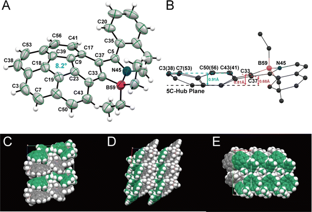
Slow evaporation of a dichloromethane solution furnished yellow block-like racemic crystals of 1, which crystallized in the P21/n space group, with a convex form as shown in Fig. 1 and S6.† The B–N bond length is 1.601 Å, indicating a strong B–N interaction, as shown in Fig. 1A and S6A.† While the parent Cor has a homogeneous depth of 0.87 Å,32,33 bowl depth of 1 was found to vary. For instance, the perpendicular distance from the plane of the five-membered ring hub (C19–C23–C9–C39–C18 ring) to the parallel planes containing the carbon atoms C33 and C37 were found to be 0.81 Å and 0.68 Å, while the depth of the other rim carbon atoms to the bowl bottom was determined to be 0.91 Å on average (Fig. 1B). This asymmetric feature of bowl depths indicates that the steric effect of the helix motif could also affect the bowl structure of the Cor motif and change the bowl-to-bowl inversion process.8 The steric repulsion of the helix motif in 1 is reflected to the longer rim C33![[double bond, length as m-dash]](https://www.rsc.org/images/entities/char_e001.gif) C37 bond (1.41 Å) than other rim C
C37 bond (1.41 Å) than other rim C![[double bond, length as m-dash]](https://www.rsc.org/images/entities/char_e001.gif) C bonds (1.36–1.38 Å). The curvature of 1 is further evaluated by using Haddon's pi-orbital axis vector (POAV) angles.34,35 As shown in Fig. 1A, the POAV angle around the central 5-membered ring is 8.2° equal to that of pristine Cor,36 illustrating a similar curvature despite the slightly deformed bowl-structure of 1. In comparison to four-coordinate organoboron analogues with isoquinolinyl and naphthyl motifs (dihedral angles: 16.8° and 27.7°),371 has a less distorted five-membered ring (dihedral angle: N45–C5–C37–C33 9.4°). However, the structure displays an increased dihedral angle around the C5–C37 bond (dihedral angle: C35–C5–C37–C17 31.2°) due to the formation of a more stable convex form in the solid state.38
C bonds (1.36–1.38 Å). The curvature of 1 is further evaluated by using Haddon's pi-orbital axis vector (POAV) angles.34,35 As shown in Fig. 1A, the POAV angle around the central 5-membered ring is 8.2° equal to that of pristine Cor,36 illustrating a similar curvature despite the slightly deformed bowl-structure of 1. In comparison to four-coordinate organoboron analogues with isoquinolinyl and naphthyl motifs (dihedral angles: 16.8° and 27.7°),371 has a less distorted five-membered ring (dihedral angle: N45–C5–C37–C33 9.4°). However, the structure displays an increased dihedral angle around the C5–C37 bond (dihedral angle: C35–C5–C37–C17 31.2°) due to the formation of a more stable convex form in the solid state.38
Stacks of (P)- and (M)-convex enantiomers are present in the packing arrangement of complex 1. Unlike some other Cor derivatives that pack as columnar stacks in crystal form,2,3,39 (P)- and (M)-convex enantiomers of 1 are arranged alternately in a step-like fashion due to the introduced asymmetric helicene part (Fig. 1C–E). Meanwhile, the enantiomers adopt an alternating arrangement to form sheet-like structures with C–H⋯π interactions (2.911–3.122 Å) between the Ph ring of isoquinoline and corannulene in the concave direction (ESI, Fig. S6B†).
2.3 Electrochemistry and ECL
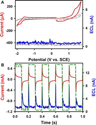
ECL is a light-emitting process triggered by electrochemical reactions.40–44 The redox and ECL behaviors of complex 1 were first investigated (Fig. 2) using instrumental set-ups illustrated in Fig. S7A and B.†Fig. 2A displays a typical ECL-voltage curve of 0.6 mM 1 in 1![[thin space (1/6-em)]](https://www.rsc.org/images/entities/char_2009.gif) :
:![[thin space (1/6-em)]](https://www.rsc.org/images/entities/char_2009.gif) 1 benzene
1 benzene![[thin space (1/6-em)]](https://www.rsc.org/images/entities/char_2009.gif) :
:![[thin space (1/6-em)]](https://www.rsc.org/images/entities/char_2009.gif) MeCN solution containing 0.1 M tetrabutylammonium hexafluorophosphate (TBAPF6) as the supporting electrolyte, along with its cyclic voltammogram (CV). Complex 1 shows a quasi-reversible reduction at E0′ = −1.67 V vs. SCE to form a radical anion. This observation agrees with the fact that Cor can be reduced up to a tetraanion in a series of one-electron reductions, as described by the pioneering work on its reduction reactions with alkaline metals such as Li and K by Rabinovitz and Scott et al.45 The radical anion 1.- is therefore visualized as an aromatic 5C/6e core suspended within an aromatic 15C/15e rim from neutral 1 of the aromatic 5C/6e core within the aromatic 15C/14e rim as in the model “annulene within an annulene”. From the DFT calculations shown in the ESI,† it seems that the helix attachment in 1 does contribute to the non-degenerate LUMO. As depicted in Fig. 2A, 1 undergoes oxidation irreversibly at Epa = 1.21 V vs. SCE to produce a radical cation. This irreversibility might be due to Jahn–Teller vibronic distortion caused by corannulene radical cation instability in its original C5v molecular arrangement via breaking the degeneracy in HOMOs, similar to the process of removing a π-electron using UV 193 nm photoionization with Cor in the gas phase.46 Again, it seems that the helix attachment in 1 does contribute to the HOMO as observed from the molecular orbital picture in the ESI.†
MeCN solution containing 0.1 M tetrabutylammonium hexafluorophosphate (TBAPF6) as the supporting electrolyte, along with its cyclic voltammogram (CV). Complex 1 shows a quasi-reversible reduction at E0′ = −1.67 V vs. SCE to form a radical anion. This observation agrees with the fact that Cor can be reduced up to a tetraanion in a series of one-electron reductions, as described by the pioneering work on its reduction reactions with alkaline metals such as Li and K by Rabinovitz and Scott et al.45 The radical anion 1.- is therefore visualized as an aromatic 5C/6e core suspended within an aromatic 15C/15e rim from neutral 1 of the aromatic 5C/6e core within the aromatic 15C/14e rim as in the model “annulene within an annulene”. From the DFT calculations shown in the ESI,† it seems that the helix attachment in 1 does contribute to the non-degenerate LUMO. As depicted in Fig. 2A, 1 undergoes oxidation irreversibly at Epa = 1.21 V vs. SCE to produce a radical cation. This irreversibility might be due to Jahn–Teller vibronic distortion caused by corannulene radical cation instability in its original C5v molecular arrangement via breaking the degeneracy in HOMOs, similar to the process of removing a π-electron using UV 193 nm photoionization with Cor in the gas phase.46 Again, it seems that the helix attachment in 1 does contribute to the HOMO as observed from the molecular orbital picture in the ESI.†
In the annihilation process where the radical cation and anion meet to react, an emitting excited state is formed if the electrogenerated species of complex 1 have enough energetics and life times. The ECL-voltage curve does not show an appreciable ECL signal in Fig. 2A. In fact, the enthalpy of ECL generation reactions determined from the peak potentials of the redox waves (2.72 eV) is greater than that of the excitons (2.69 eV) determined from the emission peak wavelength:47,48
| Ep(R′/R′˙+) − Ep(R/R˙−) − 0.16 (eV) ≥ −ΔH° | (1) |
In comparison, the oxidation potential of the parent Cor is 1.52 V, and Cor undergoes a reversible reduction reaction with a formal potential of −1.62 V and an irreversible reduction at an Epc of −2.51 V (Fig. S8A†); these values agree very well with the values reported by Valenti, Scott, Paolucci and Marcaccio et al.14 The two ethyl groups balance the Lewis acidity of the boron atom, thus increasing the electron density of the Cor motif. Additionally, the redox potentials are all negatively shifted. As seen in Fig. S8B,†Cor produces no appreciable cathodic ECL but high anodic ECL (∼4.5 nA) during potential pulsing between −2.60 and 1.60 V at a frequency of 10 Hz, which is much stronger than that of the CV scan experiment (∼0 nA). This finding also demonstrates that radical anions of Cor are more stable than the cations. Moreover, the ECL intensity of 1 is twice as strong as that of Cor. The absolute ECL efficiencies of both Cor systems during pulsing were determined following the procedure illustrated in the ESI.†49–51 As presented in Table 1, the absolute ECL efficiency (ΦECL) of 1 is 0.00010 ± 0.00004%, which is more than 5 times higher than that of Cor (0.000017 ± 0.000007%). Possibly, the lower electro-affinity nature of π-extended 1 compared to Cor makes it more-readily oxidized to form a stabilized cation for further ECL reactions.
| Sample | Absolute ECL efficiency (%) | ||
|---|---|---|---|
| Coreactant | CV | Pulse | |
| a Ru(bpy)32+/BPO system: ΦCV = 0.53 ± 0.07%; Φpulse = 0.66 ± 0.04%. | |||
| 1 | Annihilation | — | 0.00010 ± 0.00002 |
| BPO | 0.014 ± 0.003 | 0.025 ± 0.005 | |
| Cor | Annihilation | — | 0.000017 ± 0.000006 |
| BPO | 0.00060 ± 0.00008 | 0.0030 ± 0.0006 | |
For PAHs such as perylene or pyrene, the principles in ECL studies are the same. For instance, perylenetetracarboxylic diimide (PDI), terrylenetetracarboxylic diimide (TDI), and quaterrylenecarboxylic diimide (QDI) were investigated by Bard et al.52 All these PAH compounds undergo two reversible one-electron reductions and one reversible one-electron oxidation reaction. Their radical stability and reactivity favor the generation of excited states during ECL processes.
The effect of inversion motions of both the bowl and the helix on ECL luminescence will be discussed later in more detail.
2.4 ECL with benzoyl peroxide (BPO) as the coreactant
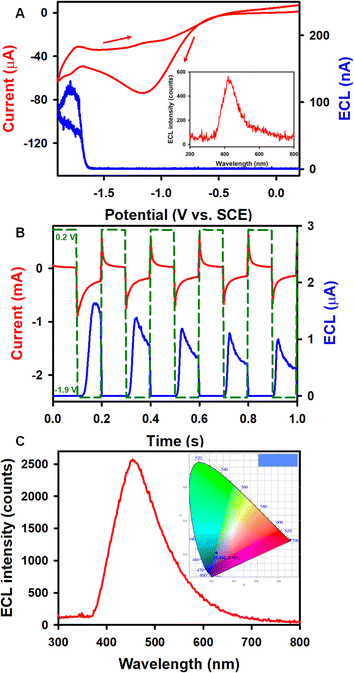
To further improve ECL performances, benzoyl peroxide (BPO) has been used as a coreactant with complex 1 (Fig. 3) in the reductive-oxidation mode14,53–55 due to high stability of the 1 radical anion as described above. Fig. 3A illustrates the ECL-voltage curve of 0.6 mM 1 with the corresponding CV in the presence of 5 mM BPO in 1![[thin space (1/6-em)]](https://www.rsc.org/images/entities/char_2009.gif) :
:![[thin space (1/6-em)]](https://www.rsc.org/images/entities/char_2009.gif) 1 benzene
1 benzene![[thin space (1/6-em)]](https://www.rsc.org/images/entities/char_2009.gif) :
:![[thin space (1/6-em)]](https://www.rsc.org/images/entities/char_2009.gif) MeCN solution. The onset of the ECL potential of the complex 1/BPO system is at about −1.62 V, right at the reduction of 1, and the ECL intensity reaches up to a maximum of 134 nA. Similarly, the onset ECL of the Cor/BPO system is located at −1.68 V, approaching a maximum ECL intensity of 5 nA, which is much lower than that of the 1/BPO system (Fig. S9A†). The absolute ECL efficiencies of these two corannulene complex-BPO systems during a CV scan were determined as illustrated in the ESI.† As displayed in Table 1, the ΦECL of the 1/BPO system is 0.014 ± 0.003%, which is more than 23 times higher than that of the Cor/BPO system (0.00060 ± 0.00008%).
MeCN solution. The onset of the ECL potential of the complex 1/BPO system is at about −1.62 V, right at the reduction of 1, and the ECL intensity reaches up to a maximum of 134 nA. Similarly, the onset ECL of the Cor/BPO system is located at −1.68 V, approaching a maximum ECL intensity of 5 nA, which is much lower than that of the 1/BPO system (Fig. S9A†). The absolute ECL efficiencies of these two corannulene complex-BPO systems during a CV scan were determined as illustrated in the ESI.† As displayed in Table 1, the ΦECL of the 1/BPO system is 0.014 ± 0.003%, which is more than 23 times higher than that of the Cor/BPO system (0.00060 ± 0.00008%).
Fig. 3B and S9B† show current–time and the corresponding ECL-time curves of 0.6 mM 1 and Cor in the presence of 5 mM BPO during a potential pulsing experiment at a frequency of 10 Hz. Notably, the pulsed-ECL of complex 1 with BPO (1.8 μA) is much stronger than that of the Cor/BPO coreactant system (0.8 μA), while the absolute ECL efficiency of the 1/BPO system (0.025 ± 0.005%) is more than 8 times higher than that of the Cor/BPO system (0.003 ± 0.0006%) (Table 1). Furthermore, the pulsed-ECL of these two corannulene complex/BPO systems demonstrates higher absolute ECL efficiencies compared with their CV-ECL in the coreactant route. Valenti, Scott, Paolucci and Marcaccio et al.14 obtained an intense ECL signal qualitatively with the 1 mM Cor/10 mM BPO coreactant system in acetonitrile solution. Please note that we report absolute ECL quantum efficiencies here, which are more quantitative. For comparison, the absolute quantum efficiency for the ECL gold standard, Ru(bpy)32+, was determined to be ΦECL-CV = 0.53 ± 0.07% and ΦECL-pulse = 0.66 ± 0.04% with BPO as the coreactant, which has been taken as 5% conventionally. Anyway, although the absolute ECL quantum efficiencies of the 1/BPO system are lower than those of the Ru(bpy)32+/BPO system, 1 represents a much stronger luminophore than Cor for ECL. This work still provides insight into development of new Cor compounds for ECL applications.
In addition, Cor generates ECL immediately when the potential is switched on in the first cycle, while there is an obvious delay (up to 0.02 s) for 1 to produce ECL. The reason might be that after the reduction of 1, repulsion would occur between the radical anions of 1 carrying negative charges and the working cathode electrode, which could accelerate the radicals to the diffusion layer to react with benzoyl radicals and emit ECL. Ultimately, shorter time intervals result in fewer decayed radicals and higher ECL efficiency.
2.5 Spooling ECL spectroscopy
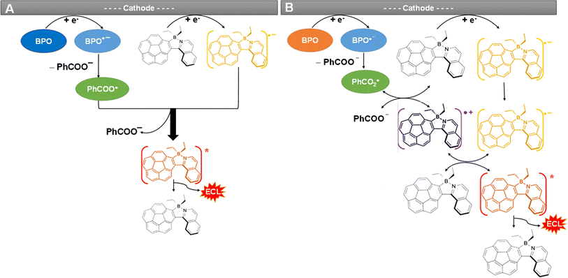
Fig. 4 and S9D† present the spooling ECL spectra of complexes 1 and Cor acquired during a CV scan upon addition of 5 mM BPO as the coreactant in the above systems. Of note, spooling ECL spectroscopy was performed by recording ECL spectra at certain time intervals during ECL generation processes,56 as previously reported by our group elsewhere. The spooling ECL spectra of both coreactant systems illustrate the evolution and devolution of the ECL process on the basis of the two proposed mechanisms. Taking complex 1 as an example, in both mechanisms, ECL is produced at −1.62 V where the 1 radical anion is generated, which aligns with the ECL-voltage curves in Fig. 3A. In Fig. 4 and S9D,† the spectra of complex 1 and Cor display consistent peak shapes and peak wavelengths during potential scans, revealing that the excited states are independent of applied potentials, thus providing evidence that an identical excited state generates ECL during the annihilation and coreactant processes. Fig. 5 illustrates the mechanisms of the coreactant ECL route with BPO. Strongly oxidizing benzoate radicals (PhCOO˙) appear after the reduction of BPO. In one way, these radicals can oxidize the radical anions of 1 produced at −1.62 V to generate the 1* excited state that emits ECL right at −1.62 V (Fig. 5A). Conversely, PhCOO˙ can also oxidize the neutral 1, and then generate radical cations of 1, which thereafter react with the radical anions of 1 to generate the excited state emitting ECL at −1.62 V (Fig. 5B). Thereby, spooling ECL spectroscopy is a powerful tool to reveal the kinetics and mechanisms of ECL processes.49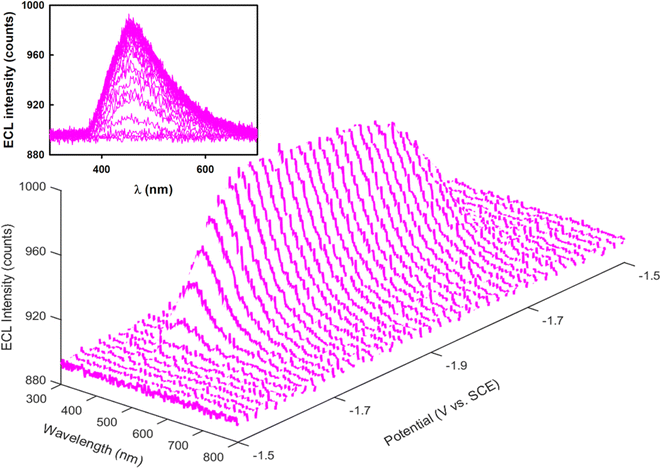 | ||
| Fig. 4 Spooling ECL spectra of 0.6 mM 1 in the presence of 5 mM BPO in potential ranges between 0.2 and −1.9 V. Inset shows the 2D viewing of the spooling ECL spectra. | ||
2.6 Absorption and luminescence spectroscopy
During the CV and the potential pulsing experiments, accumulated ECL spectra of 1 were acquired. As shown in Fig. 3A (inset) and 3C, the ECL peak wavelengths of 1 in both annihilation and coreactant pathways are 454 nm, while the ECL peak wavelength of Cor is located at 412 nm (Fig. S9C†). The UV-vis absorption and PL studies of 0.02 mM Cor and 1 were also carried out in 1![[thin space (1/6-em)]](https://www.rsc.org/images/entities/char_2009.gif) :
:![[thin space (1/6-em)]](https://www.rsc.org/images/entities/char_2009.gif) 1 benzene
1 benzene![[thin space (1/6-em)]](https://www.rsc.org/images/entities/char_2009.gif) :
:![[thin space (1/6-em)]](https://www.rsc.org/images/entities/char_2009.gif) MeCN solution. As seen in Fig. 6A, the UV-vis absorption spectrum of 1 shows maxima at 424, 402, 386, and 309 nm, with a shoulder-like absorption at around 340 nm. The PL maxima appear at 461 and 447 nm, and the absolute PL quantum yield (ΦPL) for the complex 1 is 31% (detailed determination process is given in ESI†). The Commission International de l'Éclairage (CIE) coordinates of 1 were calculated to be (0.202, 0.181) and (0.140, 0.112) based on the ECL and PL spectra, respectively. Moreover, the ECL and PL with 1 both show blue emission, as displayed in the top right corner of the CIE diagrams. The UV-vis absorption and PL spectra of Cor were also recorded. As seen in Fig. S10A,†Cor exhibits a major absorption band at around 289 nm and a PL emission with a peak wavelength of 423 nm (ΦPL = 1.0%), which is similar to the ECL variation ratio. The observation of blue luminescence in the CIE diagram (Fig. S10B†) is consistent with the literature reports.14 The ECL spectra are in good agreement with the PL, revealing that both PL and ECL rise from the same excited state. It is interesting to note that the HOMO–LUMO gaps from the DFT calculations (ESI†) is 3.51 and 4.40 eV for 1 and Cor, respectively. Compound 1 breaks the C5v symmetry for Cor, and the HOMO and LUMO lose the degeneracy, leading to a decreased HOMO–LUMO energy gap. Symmetry-breaking causes a decrease in the HOMO–LUMO energy gap, increase in the emission peak wavelength and increase in the PL quantum yield. These tendencies are very similar to those of 5,10,15,20-tetraphenyl-21H,23H-porphine zinc (ZnTPP) and 5,10,15,20-tetraphenyl-21H,23H-porphine (H2TPP).57
MeCN solution. As seen in Fig. 6A, the UV-vis absorption spectrum of 1 shows maxima at 424, 402, 386, and 309 nm, with a shoulder-like absorption at around 340 nm. The PL maxima appear at 461 and 447 nm, and the absolute PL quantum yield (ΦPL) for the complex 1 is 31% (detailed determination process is given in ESI†). The Commission International de l'Éclairage (CIE) coordinates of 1 were calculated to be (0.202, 0.181) and (0.140, 0.112) based on the ECL and PL spectra, respectively. Moreover, the ECL and PL with 1 both show blue emission, as displayed in the top right corner of the CIE diagrams. The UV-vis absorption and PL spectra of Cor were also recorded. As seen in Fig. S10A,†Cor exhibits a major absorption band at around 289 nm and a PL emission with a peak wavelength of 423 nm (ΦPL = 1.0%), which is similar to the ECL variation ratio. The observation of blue luminescence in the CIE diagram (Fig. S10B†) is consistent with the literature reports.14 The ECL spectra are in good agreement with the PL, revealing that both PL and ECL rise from the same excited state. It is interesting to note that the HOMO–LUMO gaps from the DFT calculations (ESI†) is 3.51 and 4.40 eV for 1 and Cor, respectively. Compound 1 breaks the C5v symmetry for Cor, and the HOMO and LUMO lose the degeneracy, leading to a decreased HOMO–LUMO energy gap. Symmetry-breaking causes a decrease in the HOMO–LUMO energy gap, increase in the emission peak wavelength and increase in the PL quantum yield. These tendencies are very similar to those of 5,10,15,20-tetraphenyl-21H,23H-porphine zinc (ZnTPP) and 5,10,15,20-tetraphenyl-21H,23H-porphine (H2TPP).57
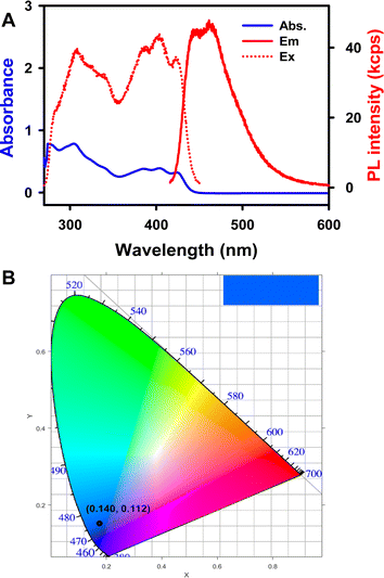 | ||
Fig. 6 (A) UV-visible absorption and photoluminescence spectra of 5 μM 1 in 1![[thin space (1/6-em)]](https://www.rsc.org/images/entities/char_2009.gif) : :![[thin space (1/6-em)]](https://www.rsc.org/images/entities/char_2009.gif) 1 benzene 1 benzene![[thin space (1/6-em)]](https://www.rsc.org/images/entities/char_2009.gif) : :![[thin space (1/6-em)]](https://www.rsc.org/images/entities/char_2009.gif) MeCN (volume ratio) solution, λex = 403 nm and λem = 451 nm. (B) The CIE coordinate diagram of the PL spectrum. MeCN (volume ratio) solution, λex = 403 nm and λem = 451 nm. (B) The CIE coordinate diagram of the PL spectrum. | ||
2.7 Chemiluminescence
The CL properties of complexes 1 and Cor were explored through excitation by assessing the chemical energy released during the reaction of a phenyl peroxyoxalate ester with hydrogen peroxide (instrumentation is shown in Fig. S7C†). In Fig. 7A, bright blue CL emission can be visually observed in a dark room after adding 0.25 mL 30% H2O2 to 1 mL of a 4![[thin space (1/6-em)]](https://www.rsc.org/images/entities/char_2009.gif) :
:![[thin space (1/6-em)]](https://www.rsc.org/images/entities/char_2009.gif) 1 N,N-dimethylformamide (DMF)
1 N,N-dimethylformamide (DMF)![[thin space (1/6-em)]](https://www.rsc.org/images/entities/char_2009.gif) :
:![[thin space (1/6-em)]](https://www.rsc.org/images/entities/char_2009.gif) MeCN (volume ratio) solution containing 1.5 mg per mL 1, 10 mg per mL bis(2,4,5-trichloro-6-(pentyloxycarbonyl)phenyl)-oxalate (CPPO) and 2 mg per mL sodium salicylate. As illustrated in Fig. S11,† CPPO reacts with H2O2 in the presence of a base catalyst (sodium salicylate) to generate oxalyl chloride and produce a high-energy intermediate (1,2-dioxetanedione), which finally decomposes into CO2.58 The released energy from this exothermic reaction can support the production of 1* from complex 1. Subsequently, the relaxation of 1* to its ground state generates CL emission. The difference between CL and ECL is that the energy in the CL reaction required to generate emissive excited state species originates from chemical reactions instead of an electrical current, which is more convenient and faster than ECL.51,59–61
MeCN (volume ratio) solution containing 1.5 mg per mL 1, 10 mg per mL bis(2,4,5-trichloro-6-(pentyloxycarbonyl)phenyl)-oxalate (CPPO) and 2 mg per mL sodium salicylate. As illustrated in Fig. S11,† CPPO reacts with H2O2 in the presence of a base catalyst (sodium salicylate) to generate oxalyl chloride and produce a high-energy intermediate (1,2-dioxetanedione), which finally decomposes into CO2.58 The released energy from this exothermic reaction can support the production of 1* from complex 1. Subsequently, the relaxation of 1* to its ground state generates CL emission. The difference between CL and ECL is that the energy in the CL reaction required to generate emissive excited state species originates from chemical reactions instead of an electrical current, which is more convenient and faster than ECL.51,59–61
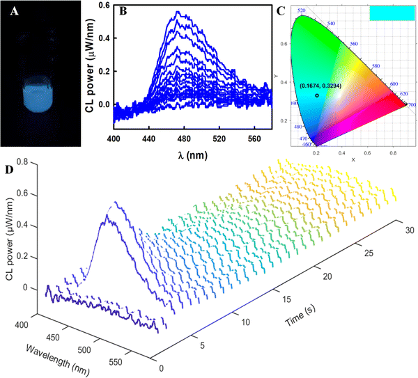
Spooling CL spectroscopy was utilized to monitor CL evolution and devolution processes, which we have demonstrated for a thermally activated delayed fluorescence emitter, porphyrin, as well as luminol, graphene quantum dots and other luminophores.55,58,61,62Fig. 7D displays the spooling CL spectra of this reaction system, where each spectrum was collected for 1 s for a total time of 30 s. With the addition of H2O2 into a solution containing 1, CPPO and sodium salicylate, the broad emission peaks are centered at 472 nm and they are independent of the time (Fig. 7B). The calculated color with coordinates of (0.167, 0.329) (Fig. 7C) from the CIE color diagram matches well with the photograph (Fig. 7A). All above results closely match the emission observed in the PL and ECL in the coreactant pathway, suggesting that a single excited state of 1 is produced in these three excitation strategies. Thus, complex 1 is a promising luminophore in various light-emitting applications.
Notably, a relatively weak blue CL emission (Fig. S12A†) can be observed by the naked eyes in a dark room after adding 1 mL 30% H2O2 to 1 mL of a 4![[thin space (1/6-em)]](https://www.rsc.org/images/entities/char_2009.gif) :
:![[thin space (1/6-em)]](https://www.rsc.org/images/entities/char_2009.gif) 1 DMF
1 DMF![[thin space (1/6-em)]](https://www.rsc.org/images/entities/char_2009.gif) :
:![[thin space (1/6-em)]](https://www.rsc.org/images/entities/char_2009.gif) MeCN solution containing 6 mg per mL Cor, 40 mg per mL CPPO and 2 mg per mL sodium salicylate, with the concentration being 4 times higher than that of 1. Moreover, the CL intensity of Cor is so weak that it could not be detected by the same spectrometer even using a higher concentration solution. In turn, the CL light of Cor was measured by using a spectrograph/CCD camera setup, as illustrated in Fig. S7D.† A weak emission peak can be observed at 434 nm, and the CL intensity of Cor shown in Fig. S12B† is much smaller than that of complex 1. As shown in the CIE color diagrams, the CL emission has coordinates of (0.244, 0.241) (Fig. S12C†), correlating with the photograph. These results also closely match the emission observed in the PL and ECL coreactant pathways, leading to the conclusion that one excited state is observed here.
MeCN solution containing 6 mg per mL Cor, 40 mg per mL CPPO and 2 mg per mL sodium salicylate, with the concentration being 4 times higher than that of 1. Moreover, the CL intensity of Cor is so weak that it could not be detected by the same spectrometer even using a higher concentration solution. In turn, the CL light of Cor was measured by using a spectrograph/CCD camera setup, as illustrated in Fig. S7D.† A weak emission peak can be observed at 434 nm, and the CL intensity of Cor shown in Fig. S12B† is much smaller than that of complex 1. As shown in the CIE color diagrams, the CL emission has coordinates of (0.244, 0.241) (Fig. S12C†), correlating with the photograph. These results also closely match the emission observed in the PL and ECL coreactant pathways, leading to the conclusion that one excited state is observed here.
The absolute CL quantum efficiency (ΦCL) is defined as the number of photons produced per CPPO molecule, which is the limiting species in this CL reaction.51,58,61 The number of photons per spectrum can be determined by using a spectrometer (USB2000+, Ocean Insight, Orlando, FL) after integration of each spectrum in the wavelength range of interest (400–700 nm), as descripted in the ESI.† The total number of photons can be determined by summing each spooling CL spectrum over the entire experiment. The ΦCL of complex 1 was determined as displayed in Table 2. The ΦCL increased gradually on increasing the solution concentrations and reached a maximum value of 0.020% ± 0.004, which is 222 times greater than that of Ru(bpy)32+ (ΦCL = 0.00009 ± 0.00001%).51 To obtain a μW-wavelength curve, the CL spectrum measured on the CCD camera was then divided by the conversion curve as we reported earlier (Fig. S12D, further details are in the ESI†).7 However, the ΦCL of Cor is only 0.00080 ± 0.00007%, which is 25 times lower than that of 1. In comparison with classical PL, the concentrations of various substances should be considered in the study of optical properties of CL and ECL, because their reactions usually involve several reactants. Detection limits for CL and ECL should be much lower than that of PL, since no light source is needed for CL and ECL.
2.8 Dynamic inversion behaviors
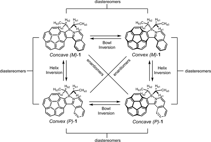
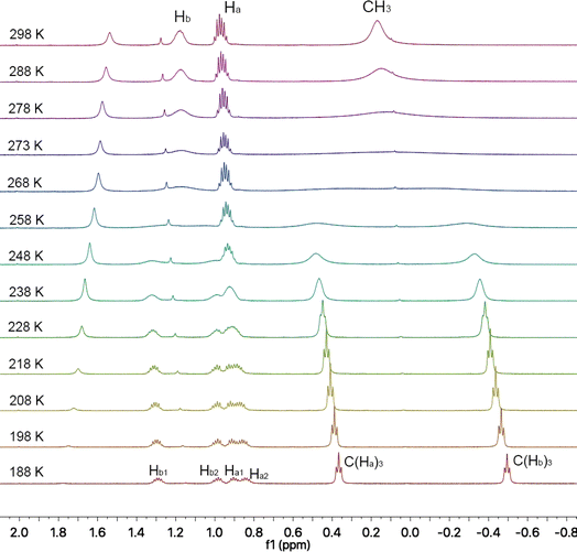
Azaborahelicene corannulene 1 undergoes two types of inversion motions: bowl and helix inversions, leading to four stereoisomers. The details are illustrated in Fig. 8. NMR chemical shifts of all the three protons (Ha and Hb in CH2 and others in CH3) in ethyl groups on 1 at room temperature were assigned to multiple peaks between 1.00 and 0.90 ppm, a single peak at 1.17 ppm and a single peak at 0.19 ppm, respectively, as shown in the spectrum at 298 K in Fig. 9. These three types of protons are situated in different chemical environments, with spatial proximity to the corannulene and helix motifs. It is anticipated that slowing down the inversion at a lower temperature will lead to splits of the three proton chemical shifts. To understand the effects of bowl and helix dynamic inversions in molecule 1 on its CL and ECL efficiencies, variable-temperature (VT) 1H NMR experiments were performed in CD2Cl2 at 600 MHz, covering a temperature range from 298 K to 188 K with 10 K increments (Fig. 9). Select spectra also were acquired upon heating back from 188 K to 298 K, which showed that all the dynamic processes were reversible (Fig. S13†). Depending on the rate of bowl and helix inversion processes in 1 on the NMR timescale, the protons of two ethyl groups situated in different chemical environments could split to two sets of signals. VT 1H NMR spectra acquired at a decreased temperature are a bit complicated; the Hb and CH3 signals in closer spatial proximity to the helix motif exhibited nearly identical coalescence temperatures (∼273 K), while the Ha signal situated near the corannulene motif showed a significantly lower coalescence temperature (238 K). A plausible explanation is that the stereoisomerism caused by helicene inversion (P/M isomers) predominantly influences the chemical environments of Hb and CH3 hydrogens, while the effects of stereoisomerism due to bowl inversion (convex/concave isomers) are negligible. The situation is precisely the reverse for Ha. A simple conclusion was quite clear: Hb and CH3 signals in VT 1H NMR spectra were mainly affected by the helicene inversion process, while Ha signals were mainly influenced by the bowl inversion process, as illustrated by Fig. S17.† A detailed explanation can be found in the section “More details on 1H NMR analysis” in the ESI.† This surprising discovery enabled the observation of the bowl and helix inversion processes of complex 1 in the VT 1H NMR spectra simultaneously, as shown in Fig. 9. In the literature, Scott et al.5 utilized dimethylcarbinol and Siegel et al.7 used ethyl to probe corannulene bowl-to-bowl inversion. For the first time, we employed Hb, CH3, and Ha to probe the inversions of both the helicene and bowl, respectively.Dynamic 1H NMR line-shape simulations were conducted to determine the values of the rate constants (k) at various temperatures and to estimate the coalescence temperature (Tc) value of both bowl and helix inversion of 1.7,63 The Eyring equation (ΔG‡c = −RT![[thin space (1/6-em)]](https://www.rsc.org/images/entities/char_2009.gif) ln(kh/kBT)) was then used to calculate ΔG‡c values at coalescence temperature Tc, and the Eyring plot was used to determine ΔH‡ and ΔS‡ values. The equation, ΔG‡ = ΔH‡ − TΔS‡, was used to calculate the ΔG‡298K values at room temperature (298 K) for comparing energy barriers. (see ESI Fig. S13–S16† for more details).
ln(kh/kBT)) was then used to calculate ΔG‡c values at coalescence temperature Tc, and the Eyring plot was used to determine ΔH‡ and ΔS‡ values. The equation, ΔG‡ = ΔH‡ − TΔS‡, was used to calculate the ΔG‡298K values at room temperature (298 K) for comparing energy barriers. (see ESI Fig. S13–S16† for more details).
The energy barriers ΔG‡298K of helix motif inversion in 1 are experimentally found to be 12.0 kcal mol−1 for CH3 signals and 12.9 kcal mol−1 for Hb signals. A value of 12.0 kcal mol−1 is chosen for the energy barrier of helix motif inversion, as helix inversion is more responsive to changes in the chemical environment and aligns more accurately with the Eyring plot, as shown in Fig. S14, S16A andB.† Besides, the energy barrier ΔG‡298K of the bowl inversion is experimentally found to be 12.7 kcal mol−1, reflecting the steric influence of the helix motif on the corannulene motif during the inversion process. The first experimental bowl inversion energy barrier of corannulene with diastereotopic protons was determined to be 10.2 kcal mol−1 by Scott et al. in 1992, which corresponds to 200![[thin space (1/6-em)]](https://www.rsc.org/images/entities/char_2009.gif) 000 times inversion per second at room temperature.5Cor should have faster bowl inversions. In comparison, the determined rates of helix and bowl inversion in 1 at room temperature are 10
000 times inversion per second at room temperature.5Cor should have faster bowl inversions. In comparison, the determined rates of helix and bowl inversion in 1 at room temperature are 10![[thin space (1/6-em)]](https://www.rsc.org/images/entities/char_2009.gif) 000 and 3000 times per second, respectively. This observation indicates that the introduction of the azaborahelical structure effectively decelerates the inversion rate of the corannulene motif. As the dynamic inversion behavior of corannulene was found to increase non-radiative loss of excited energy, the enhanced CL, ECL, and PL efficiencies of 1, as compared to those of Cor, are partially attributed to the restricted bowl-to-bowl inversion motions. Restriction of intramolecular inversion motions (RIIM) in complex 1 is similar to the aggregation-induced emission (AIE) and crystallization-induced ECL (CIECL),19,23,64 where restricted intramolecular rotations (RIR) lead to reduction in excited state energy loss. However, the luminescence efficiencies in this case are enhanced through a distinct mechanism. This study is the first to experimentally demonstrate that luminescence efficiency can be increased by RIIM, offering not just a complementary route to existing emission enhancement strategies but also paving the way for innovative designs in luminescent materials based on bowl-shaped aromatic hydrocarbons with enhanced efficiencies and functionalities.
000 and 3000 times per second, respectively. This observation indicates that the introduction of the azaborahelical structure effectively decelerates the inversion rate of the corannulene motif. As the dynamic inversion behavior of corannulene was found to increase non-radiative loss of excited energy, the enhanced CL, ECL, and PL efficiencies of 1, as compared to those of Cor, are partially attributed to the restricted bowl-to-bowl inversion motions. Restriction of intramolecular inversion motions (RIIM) in complex 1 is similar to the aggregation-induced emission (AIE) and crystallization-induced ECL (CIECL),19,23,64 where restricted intramolecular rotations (RIR) lead to reduction in excited state energy loss. However, the luminescence efficiencies in this case are enhanced through a distinct mechanism. This study is the first to experimentally demonstrate that luminescence efficiency can be increased by RIIM, offering not just a complementary route to existing emission enhancement strategies but also paving the way for innovative designs in luminescent materials based on bowl-shaped aromatic hydrocarbons with enhanced efficiencies and functionalities.
3 Conclusions
In summary, we have designed and synthesized an azabora[5]helicene corannulene 1 by introducing isoquinoline as a chelating ligand and further bridged by using boron with an electrophilic aromatic borylation. The azabora-helicene–corannulene hybrid structure was further confirmed by X-ray crystallography. As expected, the rationally designed 1 produced a strong blue light emission. Specifically, Cor hybrid 1 showed a notable increase in absolute PL quantum yield, increasing from 1% to 31%, and absolute quantum efficiencies of CL, and ECL using benzoyl peroxide as a coreactant, increasing from 0.0008% to 0.02%, and 0.003% to 0.025%, respectively. Furthermore, the mutually influencing inversion motions of the bowl and helix motifs in 1 were investigated through VT 1H NMR technology, revealing that the bowl inversion rate was effectively decelerated by a steric repulsion effect of the helix motif, which contributed to enhanced CL, ECL and PL efficiencies via reducing the non-radiative loss of excited state energy. This enhancement in luminescence caused by reduction in bowl inversion is an alternative way to mimic AIE and crystallization-induced ECL (CIECL) phenomena caused by restricted intramolecular rotations. Although the all-carbon corannulene–helicene hybrid reported by Scott et al.65 is more rigid than 1, it doesn't mean the bowl-to-bowl inversion could be better lowered as the π-extended rigid helix motif could further flatten the bowl structure and facilitate the inversion process of the corannulene motif. These findings provide fundamental insights into enhancing quantum efficiencies by rationally modulating the molecular structure and geometry of corannulene-based species. Meanwhile, utilizing these enhanced corannulene derivatives with a suitable coreactant opens a new path for the future development of efficient light-emitting devices and diagnostic immunoassays.Data availability
Original experimental data is available upon request.Author contributions
Z. D. and J. H. conceived and directed the project and designed the experiments. X. Q., L. H. and Z. Z. performed all the experiments and analyzed the results. L. H. carried out the crystallographic studies and Q. W. performed the DFT calculations. X. Q., L. H. and Z. D. prepared the manuscript. Z. D. finalized the paper.Conflicts of interest
There are no conflicts to declare.Acknowledgements
This research was supported by the Natural Sciences and Engineering Research Council of Canada [NSERC, DG RGPIN-2013-201697, DG RGPIN-2018-06556, DG RGPIN-2023-05337 and SPG STPGP-2016-493924 (Z. D.)], New Frontiers in Research Fund [NFRFR-2021-00272 (Z. D.)], National Natural Science Foundation of China [22004034 (X. Q.)], and the China Scholarship Council [CSC, 201908430010 (X. Q.)]. L. H., P. F., and J. H. gratefully acknowledge the National Natural Science Foundation of China (NSFC) (grant number 21672159) and the National Program on Key Basic Research Project of China (973 Program) (2015CB856500). We appreciate the leadership and knowledge on synthesis and quantum chemistry of corannulenes provided by Drs Jay Siegel and Kim Baldridge during their time at Tianjin University. We also acknowledge the Electronic Shop, the NMR facility manager Dr Mathew Willans in the Department of Chemistry, and Science Stores at Western University for their great service. Prof. Ruizhong Zhang at Tianjin University is acknowledged for providing various help. Dedicated to Prof. Allen J. Bard for his more than 5 decades' pioneering contributions to electrochemical science.References
- T. Guo, A. Li, J. Xu, K. K. Baldridge and J. Siegel, Angew. Chem., Int. Ed., 2021, 60, 25809–25814 CrossRef CAS PubMed.
- X. Tian, J. Xu, K. K. Baldridge and J. S. Siegel, Angew. Chem., Int. Ed., 2020, 59, 1460–1464 CrossRef CAS PubMed.
- Y. T. Wu, D. Bandera, R. Maag, A. Linden, K. K. Baldridge and J. S. Siegel, J. Am. Chem. Soc., 2008, 130, 10729–10739 CrossRef CAS PubMed.
- A. Borchardt, A. Fuchicello, K. V. Kilway, K. K. Baldridge and J. S. Siegel, J. Am. Chem. Soc., 1992, 114, 1921–1923 CrossRef CAS.
- L. T. Scott, M. M. Hashemi and M. S. Bratcher, J. Am. Chem. Soc., 1992, 114, 1920–1921 CrossRef CAS.
- T. J. Seiders, K. K. Baldridge, E. L. Elliott, G. H. Grube and J. S. Siegel, J. Am. Chem. Soc., 1999, 121, 7439–7440 CrossRef CAS.
- M. Juricek, N. L. Strutt, J. C. Barnes, A. M. Butterfield, E. J. Dale, K. K. Baldridge, J. F. Stoddart and J. S. Siegel, Nat. Chem., 2014, 6, 222–228 CrossRef CAS PubMed.
- T. J. Seiders, K. K. Baldridge, G. H. Grube and J. S. Siegel, J. Am. Chem. Soc., 2001, 123, 517–525 CrossRef CAS PubMed.
- A. Ayalon, M. Rabinovitz, P.-C. Cheng and L. T. Scott, Angew. Chem., Int. Ed., 1992, 31, 1636–1637 CrossRef.
- A. V. Zabula, A. S. Filatov, S. N. Spisak, A. Y. Rogachev and M. A. Petrukhina, Science, 2011, 333, 1008–1011 CrossRef CAS PubMed.
- A. Ayalon, A. Sygula, P. C. Cheng, M. Rabinovitz, P. W. Rabideau and L. T. Scott, Science, 1994, 265, 1065–1067 CrossRef CAS PubMed.
- C. Bruno, R. Benassi, A. Passalacqua, F. Paolucci, C. Fontanesi, M. Marcaccio, E. A. Jackson and L. T. Scott, J. Phys. Chem. B, 2009, 113, 1954–1962 CrossRef CAS PubMed.
- J. Mack, P. Vogel, D. Jones, N. Kaval and A. Sutton, Org. Biomol. Chem., 2007, 5, 2448–2452 RSC.
- G. Valenti, C. Bruno, S. Rapino, A. Fiorani, E. A. Jackson, L. T. Scott, F. Paolucci and M. Marcaccio, J. Phys. Chem. C, 2010, 114, 19467–19472 CrossRef CAS.
- J. S. Ham, J. Chem. Phys., 1953, 21, 756–758 CrossRef CAS.
- J. Dey, A. Y. Will, R. A. Agbaria, P. W. Rabideau, A. H. Abdourazak, R. Sygula and I. M. Warner, J. Fluoresc., 1997, 7, 231–236 CrossRef CAS.
- C. Si, T. Wang, A. K. Gupta, D. B. Cordes, A. M. Z. Slawin, J. S. Siegel and E. Zysman-Colman, Angew. Chem., Int. Ed., 2023, 62, e202309718 CrossRef CAS PubMed.
- J. D. Luo, Z. L. Xie, J. W. Y. Lam, L. Cheng, H. Y. Chen, C. F. Qiu, H. S. Kwok, X. W. Zhan, Y. Q. Liu, D. B. Zhu and B. Z. Tang, Chem. Commun., 2001, 1740–1741, 10.1039/B105159h.
- B. Z. Tang, Z. Zhao, H. Zhang and J. W. Y. Lam, Angew. Chem., Int. Ed., 2020, 59, 9888–9907 CrossRef PubMed.
- M. Grandl, Y. Sun and F. Pammer, Org. Chem. Front., 2018, 5, 336–352 RSC.
- Y. Min, C. Dou, D. Liu, H. Dong and J. Liu, J. Am. Chem. Soc., 2019, 141, 17015–17021 CrossRef CAS PubMed.
- R. Zhao, C. Dou, Z. Xie, J. Liu and L. Wang, Angew. Chem., Int. Ed., 2016, 55, 5313–5317 CrossRef CAS PubMed.
- Z. Huang, S. Wang, R. D. Dewhurst, N. V. Ignat'ev, M. Finze and H. Braunschweig, Angew. Chem., Int. Ed., 2020, 59, 8800–8816 CrossRef CAS PubMed.
- S. K. Mellerup and S. Wang, Trends Chem., 2019, 1, 77–89 CrossRef CAS.
- D. Frath, J. Massue, G. Ulrich and R. Ziessel, Angew. Chem., Int. Ed., 2014, 53, 2290–2310 CrossRef CAS PubMed.
- A. Wakamiya, T. Taniguchi and S. Yamaguchi, Angew. Chem., Int. Ed., 2006, 45, 3170–3173 CrossRef CAS PubMed.
- L. Jiang, Y. Wang, D. Tan, X. Chen, T. Ma, B. Zhang and D.-T. Yang, Chem. Sci., 2022, 13, 5597–5605 RSC.
- Z. Dominguez, R. Lopez-Rodriguez, E. Alvarez, S. Abbate, G. Longhi, U. Pischel and A. Ros, Chem.–Eur. J., 2018, 24, 12660–12668 CrossRef CAS PubMed.
- S. J. Cyvin, E. Brendsdal, J. Brunvoll and M. Skaret, J. Mol. Struct., 1991, 247, 119–127 CrossRef CAS.
- Y. Wang, H. Jiang, X. Liu, J. Xu, Y. Gao and N. S. Finney, Chem. Commun., 2021, 57, 5818–5821 RSC.
- N. Ishida, T. Moriya, T. Goya and M. Murakami, J. Org. Chem., 2010, 75, 8709–8712 CrossRef CAS PubMed.
- J. C. Hanson and C. E. Nordman, Acta Crystallogr., Sect. B: Struct. Crystallogr. Cryst. Chem., 1976, 32, 1147–1153 CrossRef.
- T. J. Seiders, K. K. Baldridge, G. H. Grube and J. S. Siegel, J. Am. Chem. Soc., 2001, 123, 517–525 CrossRef CAS PubMed.
- R. C. Haddon, Science, 1993, 261, 1545–1550 CrossRef CAS PubMed.
- R. C. Haddon, J. Phys. Chem. A, 2001, 105, 4164–4165 CrossRef CAS.
- H. Becker, L. T. Scott and D. K. Bohme, Int. J. Mass Spectrom. Ion Processes, 1997, 167–168, 519–524 CrossRef.
- V. F. Pais, M. M. Alcaide, R. Lopez-Rodriguez, D. Collado, F. Najera, E. Perez-Inestrosa, E. Alvarez, J. M. Lassaletta, R. Fernandez, A. Ros and U. Pischel, Chem.–Eur. J., 2015, 21, 15369–15376 CrossRef CAS PubMed.
- T. Fujikawa, D. V. Preda, Y. Segawa, K. Itami and L. T. Scott, Org. Lett., 2016, 18, 3992–3995 CrossRef CAS PubMed.
- Z.-Y. Guo, C.-X. Li, M. Gao, X. Han, Y.-J. Zhang, W.-J. Zhang and W.-W. Li, Angew. Chem., Int. Ed., 2021, 60, 2 CrossRef CAS.
- J. Descamps, C. Colin, G. Tessier, S. Arbault and N. Sojic, Angew. Chem., Int. Ed., 2023, 62, e202218574 CrossRef CAS PubMed.
- Y. Wang, J. Ding, P. Zhou, J. Liu, Z. Qiao, K. Yu, J. Jiang and B. Su, Angew. Chem., Int. Ed., 2023, 62, e202216525 CrossRef CAS PubMed.
- K. Wu, R. Chen, Z. Zhou, X. Chen, Y. Lv, J. Ma, Y. Shen, S. Liu and Y. Zhang, Angew. Chem., Int. Ed., 2023, 62, e202217078 CrossRef CAS PubMed.
- X. Wei, M. J. Zhu, Z. Cheng, M. Lee, H. Yan, C. S. Lu and J. J. Xu, Angew. Chem., Int. Ed., 2019, 58, 3162–3166 CrossRef CAS PubMed.
- W. Guo, H. Ding, C. Gu, Y. Liu, X. Jiang, B. Su and Y. Shao, J. Am. Chem. Soc., 2018, 140, 15904–15915 CrossRef CAS PubMed.
- M. Baumgarten, L. Gherghel, M. Wagner, A. Weitz, M. Rabinovitz, P.-C. Cheng and L. T. Scott, J. Am. Chem. Soc., 1995, 117, 6254–6257 CrossRef CAS.
- H. A. Galué, C. A. Rice, J. D. Steill and J. Oomens, J. Chem. Phys., 2011, 134, 054310 CrossRef PubMed.
- N. E. Tokel, C. P. Keszthelyi and A. J. Bard, J. Am. Chem. Soc., 1972, 94, 4872–4877 CrossRef CAS.
- L. Yang, L. Dong, D. Hall, M. Hesari, Y. Olivier, E. Zysman-Colman and Z. Ding, SmartMat, 2022, 4, e1149 CrossRef.
- J. R. Adsetts, K. Chu, M. Hesari, J. Ma and Z. Ding, Anal. Chem., 2021, 93, 11626–11633 CrossRef CAS PubMed.
- A. Fracassa, C. Mariani, M. Marcaccio, G. Xu, N. Sojic, G. Valenti and F. Paolucci, Curr. Opin. Electrochem., 2023, 41, 101375 CrossRef CAS.
- Z. Zhan, X. Qin, K. Chu, X. Sun and Z. Ding, J. Electroanal. Chem., 2023, 932, 117220 CrossRef CAS.
- S. K. Lee, Y. Zu, A. Herrmann, Y. Geerts, K. Müllen and A. J. Bard, J. Am. Chem. Soc., 1999, 121, 3513–3520 CrossRef CAS.
- X. Qin, L. Yang, X. Wang, D. Patel, K. Chu, L. Kelland, J. Adsetts, C. Zhang, M. S. Workentin, B. Pagenkopf and Z. Ding, ChemElectroChem, 2022, 9, e202200605 CrossRef CAS.
- X. Qin, L. Yang, Z. Zhan, E. Cieplechowicz, K. Chu, C. Zhang, S. Jahanghiri, G. C. Welch and Z. Ding, Electrochim. Acta, 2023, 450, 142226 CrossRef CAS.
- C. Zhang, R. Zhang, R. Zhang, Q. Zhang, J.-L. Zhang and Z. Ding, J. Inorg. Biochem., 2024, 254, 112514 CrossRef CAS PubMed.
- M. Hesari and Z. Ding, Nat. Protoc., 2021, 16, 2109–2130 CrossRef CAS PubMed.
- R. Zhang, A. Zhang, M. J. Stillman and Z. Ding, J. Phys. Chem. C, 2020, 124, 16568–16576 CrossRef CAS.
- K. Chu, J. R. Adsetts, Z. Whitworth, S. Kumar, E. Zysman-Colman and Z. Ding, Langmuir, 2023, 39, 2829–2837 CrossRef CAS PubMed.
- A. G. Hadd, D. W. Lehmpuhl, L. R. Kuck and J. W. Birks, J. Chem. Educ., 1999, 76, 1237–1240 CrossRef CAS.
- A. Eghlimi, H. Jubaer, A. Surmiak and U. Bach, J. Chem. Educ., 2019, 96, 522–527 CrossRef CAS.
- X. Qin, Z. Zhan, R. Zhang, K. Chu, Z. Whitworth and Z. Ding, Nanoscale, 2023, 15, 3864–3871 RSC.
- X. Qin, S. Jahanghiri, Z. Zhan, K. Chu, J. Khangura and Z. Ding, Anal. Chim. Acta, 2024, 1285, 342023 CrossRef CAS PubMed.
- J. Eloranta, Experiment 3: Dynamic NMR spectroscopy, http://aa6kj.hopto.org/eloranta_lab/CHEM352L/experiment3.pdf, accessed March 1, 2024 Search PubMed.
- J. M. Wong, R. Zhang, P. Xie, L. Yang, M. Zhang, R. Zhou, R. Wang, Y. Shen, B. Yang, H.-B. Wang and Z. Ding, Angew. Chem., Int. Ed., 2020, 59, 17461–17466 CrossRef CAS PubMed.
- T. Fujikawa, D. V. Preda, Y. Segawa, K. Itami and L. T. Scott, Org. Lett., 2016, 18, 3992–3995 CrossRef CAS PubMed.
Footnotes |
| † Electronic supplementary information (ESI) available. CCDC 2337637. For ESI and crystallographic data in CIF or other electronic format see DOI: https://doi.org/10.1039/d4sc01524j |
| ‡ X. Qin, L. Huang and Z. Zhan contributed equally to this work. |
| This journal is © The Royal Society of Chemistry 2024 |

