 Open Access Article
Dual-function additive enables a self-regulatory mechanism to balance cathode–anode interface demands in Zn‖MnO2 batteries†
Yuying
Han
a,
Fangzheng
Wang
a,
Lijin
Yan
a,
Liang
Luo
a,
Yuan
Qin
a,
Chong
Zhu
a,
Jiangyu
Hao
e,
Qizhi
Chen
*d,
Xuefeng
Zou
*c,
Yang
Zhou
*b and
Bin
Xiang
 *a
*a
aCollege of Chemistry and Chemical Engineering, Chongqing University, Chongqing 401331, China. E-mail: xiangbin@cqu.edu.cn
bAnalytical and Testing Center, Chongqing University, Chongqing 401331, China. E-mail: zhouyangyang@cqu.edu.cn
cGuizhou Provincial Key Laboratory of Computational Nano-Material Science, Guizhou Education University, Guiyang 550018, Guizhou, China. E-mail: njzouxf@gznc.edu.cn
dGuangxi Huiyuan Manganese Industry Co., Ltd, Laibin 546138, Guangxi, China. E-mail: chenqizhi@southmn.com
eCollege of Chemistry and Chemical Engineering, Chongqing University of Technology, Chongqing 400054, China
First published on 2nd July 2024
Abstract
The poor reversibility of the zinc (Zn) anodes and the irreversible deposition/dissolution of Mn2+/MnO2 significantly impede the commercialization of Zn–Mn aqueous batteries (ZMABs). In reducing the difference between the desired interfacial reaction environments of the cathode and anode, we found that they face the same problem of interference-the generation of irreversible corrosion products. Herein, we have introduced a novel self-regulatory mechanism. This mechanism involves the addition of sodium dihydrogen phosphate, which shifts from passive protection to active regulation. It effectively captures OH− ions, prevents corrosion product formation, and facilitates the in situ generation of a solid electrolyte interface (SEI) film. This modification also homogenizes Zn ion flow and improves the reversibility of Zn plating and stripping. Furthermore, a stable and slightly acidic environment has been established to stabilize the pH at the cathodic interface, mitigate corrosion product formation, and enhance the reversible deposition and dissolution of Mn2+/MnO2. With the optimal electrolyte, Zn‖Zn symmetric cells demonstrate stable operation for over 3000 hours at 1 mA cm−2, 1 mA h cm−2. Additionally, the Zn‖Cu cells maintain high reversibility after 1000 cycles, achieving an average coulombic efficiency (CE) of 99.76%. The assembled Zn‖MnO2 full cells exhibit exceptional cycling stability and rate performance. This work adopts the approach of seeking common ground and emphasizing the balance of cathode and anode interfacial requirements, which represents a new and significant insight for design of ZMABs with high reversibility and high cyclability.
1 Introduction
Aqueous Zn-ion batteries (AZIBs) are among the most promising candidates for energy storage systems, favored for their high safety, high volumetric energy density (5855 mA h cm−3), low redox potential (Zn/Zn2+ at −0.76 V vs. SHE), and environmental friendliness.1–3 MnO2 is extensively used as a cathode material for AZIBs due to its theoretical specific capacity, high redox potential, abundant resources, and low toxicity.4–6 Nevertheless, the differing interface requirements between manganese-based cathodes and Zn anodes limit its application.One significant challenge is the poor reversibility of the Zn anode, which hinders the development of AZIBs.7 During the Zn plating/stripping process, massive electrons/ions accumulate at the interface, leading to polarization potential fluctuations and disordered diffusion, resulting in rampant Zn dendrite growth. Therefore, regulating the spatial electric field distribution and homogenizing Zn ion flow are critical for achieving uniform Zn deposition.8–10 Additionally, parasitic hydrogen evolution reactions (HER) produce excess OH−, leading to the formation of insulating Zn4(OH)6SO4·xH2O byproducts (ZHS). These byproducts cause non-homogeneous Zn2+ flux and electric fields at the interface,11,12 further disrupting electrodeposition and leading to irreversible imbalances. The phase transition and dissolution of manganese oxides, as well as side reactions between the electrode and electrolyte, also hinder commercialization.13 The abundance of OH− ions from the manganese dissolution reaction increases the local pH, promoting rapid formation of byproducts at the cathodic interface.14,15 Moreover, the poor electrical and ionic conductivity of these byproducts significantly limits charge transfer. Consequently, Mn2+ generated during the discharge process diffuses irreversibly into the electrolyte and does not return to the cathode surface during charging, resulting in capacity degradation through irreversible Mn2+/MnO2 deposition/dissolution reactions at the manganese cathode.16,17
The pivotal determinant of high performance in Zn–manganese batteries lies in the reversibility of both cathode and anode processes. Any imbalance in either component sets off an irreversible chain reaction. Yet, concurrently, we've noted significant disparities and even contradictions in the desired interfacial reaction environments of the cathode and anode during charging and discharging. The recognized energy storage mechanisms of ZMABs can be categorized into (1) H+ and/or Zn2+ dominated insertion/deinsertion, and (2) deposition/dissolution type electrolytic reactions (Mn2+ → Mnn+, 2 < n ≤ 4).18,19 Numerous studies have underscored the influence of pH changes on the deposition/dissolution of Mn2+/MnO2.20,21 In a 2 M ZnSO4 solution, the former necessitates proton capture to prevent excessive formation of unutilized Mn3+, while the latter requires proton provision, otherwise, creating a conducive environment for ZHS generation due to insufficient proton concentration and the formation of MnOOH and MxMnO2.19,22,23 Hence, coordinating these processes assumes paramount importance. Fluctuations in pH not only dramatically affect the reversibility of Mn2+/MnO2 deposition/dissolution but also severely impact the stability of the anode interface. Zn ion deposition, coupled with persistent HER, exacerbates the elevated local OH− concentration. These reactions can further alter the local pH and reduce the reversibility of Zn/Zn2+ by forming inactive solid byproducts like Zn oxides or hydroxides.24,25 Achieving a stable and moderately acidic environment is thus crucial for balancing efficient battery operation.
In response, numerous studies have employed decoupled electrolyte systems to segregate the operating conditions of the MnO2 cathode and the Zn anode within a single cell, enhancing the operating voltage window and significantly improving battery life.26–28 However, these systems require costly ion-selective membranes to prevent cross-mixing during cycling and are rarely used in smaller devices due to the stringent manufacturing processes.29 Alternative strategies include constructing anhydrous or water-poor environments30–34 and using electrolyte additives that have been available to regulate pH to stabilize interfacial environments, or to construct interfacial layers to inhibit parasitic reactions on Zn metals with remarkable success.35–39 These approaches have predominantly focused on suppressing undesirable phenomena at the Zn anode while often neglecting cathodic chemistry. Therefore, in the process of meeting the interface requirements of the anode and cathode in a normal system, the discussion of interface compatibility and its dynamic self-regulation mechanism is also a relatively unexplored and neglected area.
To address the simultaneous interfacial challenges faced by both the cathode and anode-particularly the generation of irreversible corrosion products-we have developed a self-regulatory mechanism by incorporating a small amount of sodium dihydrogen phosphate (NaH2PO4, denoted as SDP). This additive not only neutralizes OH− ions generated during hydrogen precipitation but also forms a protective Zn3(PO4)2·4H2O (ZnPO) layer in situ, shielding the Zn anode from further corrosive damage. Simultaneously, the generated ZnPO film can homogenize the Zn ion flow and buffer the concentration polarization caused by localized over-consumption of Zn ions. Unlike other phosphate additives, SDP actively stabilizes pH on the cathode side, capturing excess OH− ions, slowing down inert byproduct formation, promoting reversible Mn2+/MnO2 processes, and stabilizing pH fluctuations during cycling (Scheme 1). Specifically, Zn‖Zn symmetric cells can operate stably for over 3000 hours at 1 mA cm−2, 1 mA h cm−2. The deep cycle stability exceeds 180 hours (DOD = 50%, which is 5 times that of the base electrolyte.) The Zn‖Cu cell exhibits high reversibility after 1000 cycles, with an average coulombic Efficiency (CE) of 99.76%, and the assembled Zn‖MnO2 full cell delivers excellent cycling stability and multiplicity performance. This “self-regulation” strategy significantly enhances the reversibility of Zn anode plating/stripping and Mn2+/MnO2 deposition/dissolution, providing a novel approach to developing highly reversible aqueous metal batteries with practical applications.
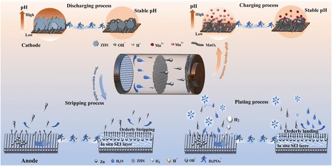 | ||
| Scheme 1 Schematic illustration of the regulation behavior of the SDP additive on the cathode and anode bilateral interface synchronously. | ||
2 Results and discussion
2.1. Stabilization of pH and inhibition of ZHS
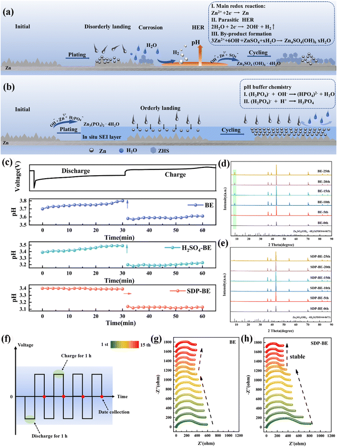
The continuous HER on the anode exacerbates the fluctuation of H+ concentration and leads to the increase of local OH− concentration (Fig. 1a). SDP counters this by binding to OH− ions through its buffering effect and in situ forms a solid electrolyte interface (SEI) film. This film specifically adsorbs onto the surface of the Zn foil, creating a protective layer that effectively inhibits the HER, mitigates electrochemical corrosion, and slows the formation of inert ZHS. The dynamic SEI adsorption layer provides steric hindrance, blocking active corrosion sites and limiting the random two-dimensional diffusion of Zn2+ ions (Fig. 1b). The in situ formation mechanism of the SEI film can be described as follows:| 2H2O + 2e− → H2↑ + 2OH− | (1) |
| 2H2PO4− + 4OH− + 3Zn2+ → Zn3(PO4)2·4H2O↓ | (2) |
In situ pH monitoring in a Zn‖Zn symmetric cell reveals that the pH in 2 M ZnSO4 (base electrolyte, BE) gradually increases during discharge and remains relatively unchanged during charging (Fig. 1c). To ensure consistency between the initial pH values of the BE and SDP-modified Zn electrolyte (SDP-BE), 0.05 mol sulfuric acid (S-BE) was used for calibration. Despite this, the pH with SDP addition remains more stable, highlighting its effectiveness in trapping elevated local OH− concentrations resulting from HER, thus stabilizing the interfacial pH and inhibiting corrosion product formation. This effect is corroborated by X-ray diffraction (XRD) patterns (Fig. 1d, and e), where a pronounced diffraction peak at 8.5°, corresponding to ZHS (PDF:44-0673),40 was observed in BE over several cycles. Furthermore, a Zn‖Zn symmetric cell was assembled and left to rest for 12 hours for in situ electrochemical impedance spectroscopy (EIS) testing. The initial reduction in charge transfer resistance (Rct) over the first nine cycles is attributed to the dissolution of loosely attached electrolyte and oxide layers, which exposes previously covered active sites.41 Beyond the tenth cycle, Rct values for the BE increase (Fig. 1g), while the SDP-BE maintains a steady state (Fig. 1h). This difference arises because ZHS continuously forms on the Zn surface during the cycling process, post the stripping of the pre-attached layers. ZHS covers the active sites, obstructing ion transport pathways and degrading cycling performance. This passive and constrained mechanism leads to the continuous accumulation of ZHS and electrolyte depletion.42,43 In contrast, the addition of SDP results in the formation of an in situ ZnPO interfacial layer, which homogenizes Zn ion flow and neutralizes the local pH increase, effectively suppressing the generation of ZHS at the source and maintaining a stable interfacial environment.
2.2. Mechanism and effects of in situ membrane formation
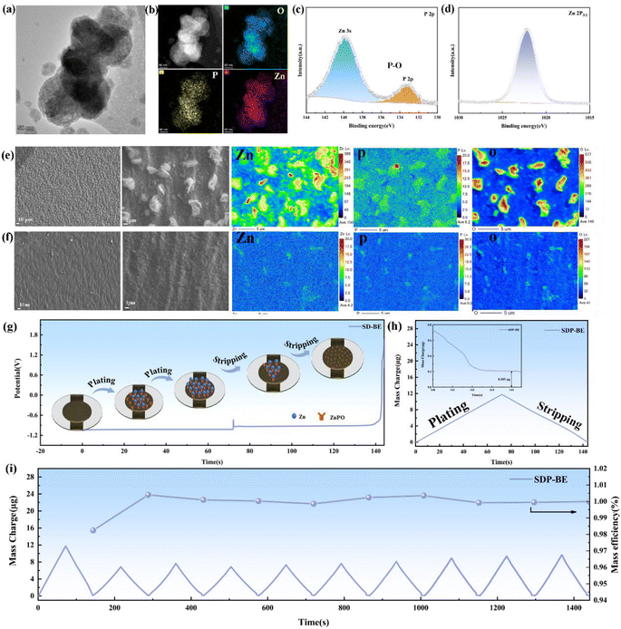
The formation of ZnPO in the self-regulatory mechanism is triggered by an increase in pH, and in order to investigate the membrane-forming mechanism, the electron probe X-ray micro analyzer (EPMA) was conducted on the copper surface during Zn deposition. The EPMA results reveal a uniform distribution of Zn, O, and P across the Zn surface (Fig. S5),† confirming the homogeneous formation of the ZnPO layer. X-ray photoelectron spectroscopy (XPS) analysis of the SDP-BE confirmed the presence of P–O bond in phosphate anions (PO43−) represented by characteristic peaks at 133.4 eV (P 2p), and the characteristic peak of the Zn 2p3/2 peak at 1022.2 eV, corresponding to the formation of an abundant Zn2+ in ZnPO (Fig. 2c and d).44–46 Transmission electron microscope (TEM) and elemental mapping support the formation of a P, O and Zn rich SEI layer on the surface (Fig. 2a and b).Further investigations into the dynamic reversibility of the ZnPO layer were conducted using ex situ EPMA (site-specific labeling technique) to analyze elemental content and distribution on the Cu foil during Zn deposition and stripping (Fig. 2e and f). Initially, the content of Zn and P during discharge was recorded at 150 and 6.2, respectively. After charging, these values decreased to 4.2 for Zn and 6.0 for P, suggesting a partial dynamic stripping of the ZnPO film concurrent with Zn stripping. In situ electro-chemical quartz crystal microbalance (EQCM) coupled with chronopotentiometry (CP) was used to monitor the mass change of the working electrode during the Zn plating/stripping processes (Fig. S6).† Based on previous validation, the 10 ng difference in mass left on the crystal sheet compared to the sample without SDP additive can be attributed to the ZnPO film (Fig. S7).†Fig. 2i illustrates the mass efficiency and mass change over ten cycles. It can be seen that after the first cycle, the deposited/stripped mass decreases and the mass efficiency is close to 100%, suggesting that ZnPO film induces reversible Zn deposition/stripping while stabilising pH fluctuations, and the ZnPO film is then in a steady and reversible state.
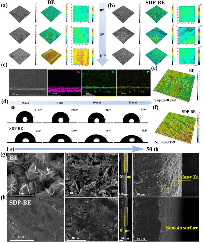
This is confirmed by the findings of white light interferometry comparing the anode surfaces for different numbers of cycles (Fig. 3a and b), where it is observed that the ZnPO film is being generated during the initial cycles and the surface of the SDP-BE became more uniform as the cycle progressed, comparing with the surface of the BE sample showing inhomogeneous adherence at 10 cycles. The cross-sectional SEM images after 10 cycles show a homogeneous ZnPO interfacial layer on the Zn surface, contrasting with the irregular ZHS coverage observed on the BE surface (Fig. 3c, and S8†). Dynamic contact angle tests conducted over 15 minutes demonstrated that the SDP-Zn electrolyte wets the Zn plate more rapidly than the BE, enhancing electrode/electrolyte contact and accelerating Zn ion migration kinetics (Fig. 3d).47 Assessing the initial deposition, the surface roughness (Sa) of BE was 0.249 μm, significantly higher than that of SDP-BE (Fig. 3e, and f). The uniform Zn ion flow and inhibition of corrosion products by the ZnPO layer contribute to a smooth and flat surface morphology observed over 1 to 50 cycles. In contrast, significant Zn dendrites and interspersed corrosion products were noted on the BE surface at both the initial and 50th cycle. Cross-sectional analysis revealed a loose and porous deposit approximately 89 μm thick on the BE surface, likely comprising a mix of corrosion products and inactive Zn (Fig. 3g, and h). The in situ formed ZnPO film by SDP-BE shields the Zn anode from corrosive media, reducing thermodynamic instability at the anode–electrolyte interface. Specifically, the addition of SDP lowered the corrosion current from 4.649 × 10⁻³ to 3.208 × 10⁻³ A cm−2 and increased the corrosion potential from −0.995 V to −0.988 V in the Tafel test, and the hydrogen precipitation potential increased from 122 mV to 132 mV in the linear sweep voltammetry test at a current density of −20 mA cm−2 (Fig. S11).†
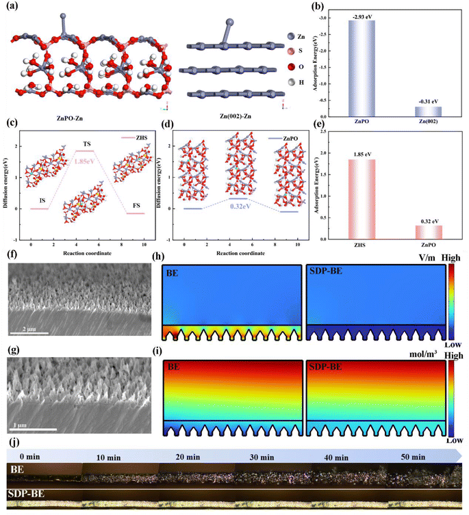
To further explore how the ZnPO interfacial layer promotes uniform Zn deposition, density functional theory (DFT) calculations were conducted. These calculations demonstrate that the adsorption energy of Zn ions on the ZnPO surface is significantly higher at −2.93 eV compared to −0.31 eV on the Zn(002) surface (Fig. 4a, and b). This suggests that ZnPO acts as a zincophilic site, preferentially capturing Zn ions and promoting homogeneous Zn galvanization under electric field influence. Moreover, theoretical simulations were performed to compare the migration energy barriers for Zn ions in ZnPO and ZHS. The results indicate that the migration energy barrier in ZnPO is much lower (0.32 eV) compared to 1.85 eV in ZHS (Fig. 4c–e), demonstrating that the ZnPO layer facilitates the rapid migration of Zn ions and immobilization by deposition. Combined with SEM images of bare Zn cross sections (Fig. 4f, and g), the COMSOL simulation results show that the addition of SDP can homogenize the local electric field and Zn ion concentration distribution for uniform galvanization (Fig. 4h, and i). Fig. 4j highlights the comparative analysis of Zn dendrite formation on BE and SDP-BE surfaces. Over time, Zn dendrites on the BE surface become progressively larger under a current density of 5 mA cm−2. In stark contrast, the SDP-BE exhibits flatter and more uniform Zn deposition under the same operational conditions.
2.3. Induced Zn ordered plating/stripping and electrochemical properties
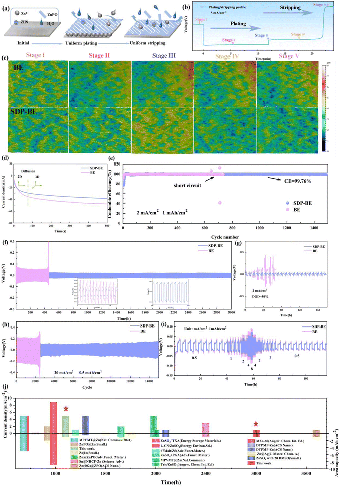
To explore the mechanism behind the SDP-BE induced reversible plating/stripping of Zn, ex situ white light interferometry was employed to monitor the morphological evolution of Zn plating/stripping at a current density of 5 mA cm−2 (Fig. 5a–c). At stage II, the bare Zn‖Cu surface exhibits an inhomogeneous distribution of Zn, with pronounced localized aggregation evident by stage III. This aggregation persists through the stripping phases (stages IV and V), leaving the Cu surface highly aggregated and inhomogeneous, which undermines the stability of subsequent Zn plating/stripping cycles. In contrast, the SDP-Zn‖Cu surface maintains a uniform Zn deposition across the entire interface, and the Cu foil surface remains relatively flat even after stripping is completed in stages IV and V. These observations confirm that the SDP additive significantly enhances the reversibility of plating/stripping in the Zn‖Cu cell.The CA test in Fig. 5d offers further insights into the Zn ion diffusion dynamics during deposition. The current density on the bare Zn surface continues to rise monotonically at 100 seconds, indicative of uncontrolled two-dimensional (2D) diffusion. Conversely, the in situ generated ZnPO buffer layer on the Zn surface curtails the rampant nucleation of Zn, thereby restricting the stochastic 2D diffusion of Zn2+ ions and mitigating the “tip effect”. The uncontrolled growth observed on the bare Zn is further highlighted by aggregation phenomena in the three-dimensional (3D) plot (Fig. S12),† which contributes to a gradual increase in nucleation resistance. In contrast, SDP-Zn results in more uniform deposition on the Zn foil surfaces, which significantly improves their electrochemical performance by stabilizing diffusion dynamics and reducing nucleation barriers.
Specifically, the SDP-Zn‖Cu asymmetric cell demonstrates a stable voltage profile up to 1500 cycles with an average CE of 99.76% at 2 mA cm−2, 1 mA h cm−2 (Fig. 5e). In contrast, the voltage profile of the BE progressively increases with each cycle, indicating degradation (Fig. S13).† Similarly, the assembled Zn‖Zn symmetric cell using SDP shows remarkable stability, sustaining 3000 hours of cycling at 1 mA cm−2, 1 mA h cm−2, significantly surpassing the endurance of the bare Zn‖Zn cell (Fig. 5f). Increasing the current to 5 mA cm−2, the SDP-Zn can be cycled stably for 1200 h, while the bare Zn has a sharp rise in polarization voltage after 200 h, leading to cell failure (Fig. S14).† The same phenomenon occurs when the current is 20 mA cm−2 and the capacity is 0.5 mA h cm−2 (Fig. 5g). In the extreme case, SDP-BE records stable cycling up to 180 h when DODZn is increased to 50%, in contrast to BE, which fails after 50 h due to a sudden drop in voltage (Fig. 5h). Furthermore, Fig. 5i illustrates that the overpotential in the SDP-BE symmetric cell remains consistently low and stable across all tested current densities, contrasting sharply with the higher overpotentials observed in the BE. These improvements in electrochemical performance validate that the SEI film generated by the self-regulatory Mechanism significantly enhances the reversibility of Zn plating/stripping reactions. Additionally, comparisons with findings from other studies highlight substantial benefits provided by SDP, affirming its superior performance (Fig. 5j).
2.4. Suppression of side reactions and full cell performance
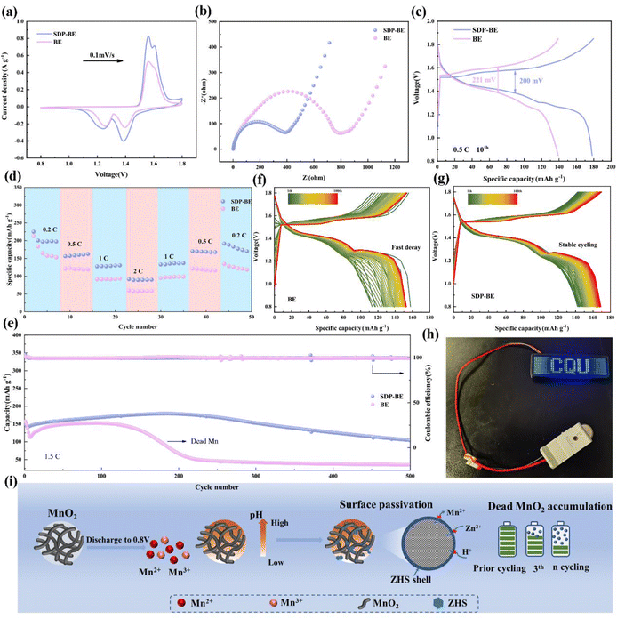
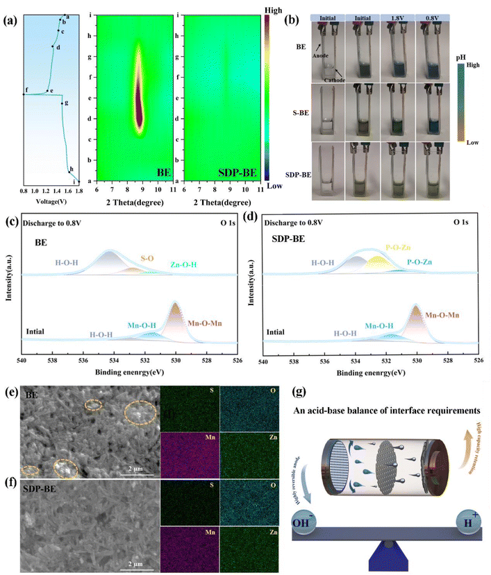
To assess the practicality of SDP additives, α-MnO2 was employed as the cathode material in full cells (Fig. S15 and S16).† The SDP-Zn‖MnO2 full cell demonstrates higher peak currents in cyclic voltammetry (CV) curves compared to the Zn‖MnO2 cell, indicating enhanced reaction kinetics (Fig. 6a). The evaluation of the EIS tests further quantifies this enhancement, where the Rct of the Zn‖α-MnO2 cell is approximately double that of the SDP-Zn‖MnO2 cell, suggesting faster electron mobility in the latter (Fig. 6b). Additionally, the SDP-Zn‖MnO2 cathode exhibits a significantly reduced potential gap (ΔE = 200 mV) between the charge and discharge plateaus compared to the Zn‖MnO2 cathode, indicating lower polarization (Fig. 6c). The practical application is further demonstrated as connecting three SDP-BE cells in series successfully powers an LED (Fig. 6h). Regarding rate capability, the SDP-Zn‖MnO2 full cell achieves a capacity recovery of 93%, significantly higher than the 77% observed with the standard Zn‖MnO2 when returning to a rate of 0.2C (Fig. 6d). At varying rates, the full cell with bare Zn shows markedly lower capacities than the SDP-Zn‖MnO2 (Fig. S17).† In a long cycling test at a rate of 1.5C, the Zn‖α-MnO2 retains only 27.1% of its initial capacity after 300 cycles, whereas the SDP-Zn|MnO2 maintains 68.7% capacity over 500 cycles (Fig. 6e), as further supported by the corresponding voltage profiles (Fig. 6f, and g). This pattern persists even at a higher rate of 2C (Fig. S18),† underscoring the instability and irreversible properties of manganese-based cathodes in BE electrolyte. The rapid capacity decay in the BE solution is primarily attributed to the abundant OH− produced by the manganese dissolution reaction, which elevates the local pH and promotes swift formation of ZHS at the cathode interface. The poor electrical and ionic conductivity of ZHS significantly hinders charge transfer. Particularly, Mn2+ generated during discharge diffuses irreversibly into the electrolyte, driven by ionic concentration gradients, and fails to return to the cathode surface during subsequent charging,48,49 exacerbating capacity decay (Fig. 6i).To investigate the rapid capacity decline in the BE‖MnO2 system, ex situ XRD was employed to analyze MnO2 at different stages of the charging and discharging process. As shown in Fig. 7a, a pronounced increase in the diffraction peak at 8.5° occurs as the discharge progresses, corresponding to the formation of ZHS (PDF:44-0673).40 Additionally, the pH stability of the BE electrolyte during the charge–discharge cycles is problematic, as illustrated by a transparent electrolytic Zn–Mn cell (Fig. 7b). The initial color of the electrolyte is deep green, which changes to blue after charging and discharging process. To minimize the starting pH error with SDP, 0.05 M H2SO4 (S-BE) is added, and the results remain the same. In contrast, the SDP-BE electrolyte in the transparent cell maintains a stable pH throughout the cycling, attributed to the dynamic and reversible neutralization of OH− and H+ by SDP.
XPS was conducted to detect changes in the chemical state of σ-MnO2. As depicted in Fig. 7c, the O 1s spectra identify peaks at 529.98, 531.55, and 533.12 eV, corresponding to Mn–O–Mn, Mn–O–H, and H–O–H bonds in pristine MnO2 nanosheets. After the 1st discharge, new peaks at 531.60, 532.40, and 533.70 eV appear, indicative of Zn–O–H, S–O, and H–O–H bonds of ZHS.50–52 For the SDP-BE, peaks corresponding to P–O–Zn in Zn(H2PO4)2/ZnHPO4 (531.12 eV), Zn3(PO4)2 (532.51 eV), and crystal water (533.86 eV) are identified (Fig. 7d).53–55 Substantial corrosion product accumulation is observed on the blank sample after one cycle (Fig. 7e), with the situation worsening after three cycles (Fig. S20).† In stark contrast, the SDP-BE surface exhibits none of these detrimental effects (Fig. 7f). These results further demonstrate the accumulation of irreversible ZHS on the cathode surface of the BE sample during the discharge process, exacerbating as the cycles continue. It is well known that maintaining the pH of the electrolyte at a weakly acidic level facilitates the maintenance of the charge storage mechanism based on the Zn2+/H+ intercalation, which is essential for reversible and stable battery operation. Therefore, a stable acid–base environment is essential for promoting efficient battery performance, as indicated by the ability of SDP to maintain such a balance (Fig. 7g).
3 Conclusion
This study adopts the approach of seeking common ground while reserving differences and emphasizing the balance of cathode and anode interfacial requirements, leading to significantly improved cycling stability in Zn–manganese batteries. Besides, we have carried out systematic experiments and theoretical calculations to reveal how the self-regulatory mechanism balances the difference in cathode and anode interfacial demands, and the excellent electrochemical performances obtained proved to be effective in enhancing the cycling stability of Zn–manganese batteries. This enhancement is primarily attributed to the addition of SDP, which forms a ZnPO interfacial layer in situ on the Zn anode. This layer is uniformly distributed across the Zn surface, creating a homogeneous electric field and Zn ion flow that facilitates uniform Zn plating and stripping. Crucially, SDP actively captures the abundant OH− ions produced by the manganese dissolution reaction, thereby preventing the formation of ZHS and promoting the reversible deposition/dissolution of Mn2+/MnO2. Thanks to these advantages, Zn‖Zn symmetric cells have demonstrated stable operation for over 3000 hours at 1 mA cm−2, 1 mA h cm−2. The Zn‖Cu cell exhibits high reversibility after 1000 cycles, with an average CE of 99.76%, and the assembled Zn‖MnO2 full cell delivers excellent cycling stability and multiplicity performance. This self-regulatory strategy represents a novel and effective method for homogenizing Zn2+ flux and enhancing the plating/stripping reversibility, marking a significant advancement in the development of practical, highly reversible aqueous Zn ion batteries. The implications of this work are profound for the future of ZMABs, providing a foundation for their practical application in energy storage systems.Data availability
The data that supporting the findings of this study are available within the article and its ESI,† or from the corresponding author on reasonable request.Author contributions
Q. C., X. Z., Y. Z., and B. X. directed the project. Y. H. performed the main experimental works. F. W., L. Y., and L. L. participate in some of experimental works. Q. Y., C. Z., and J. H. provided some constructive suggestions for the experiment. All the authors discussed the experimental results.Conflicts of interest
The authors declare no conflict of interest.Acknowledgements
This research is supported by the Opening Project of the State Key Laboratory of Advanced Chemical Power Sources, and supported in part by the National Natural Science Foundation of China (52276171). The work also acquired some supports like Guizhou Provincial Science and Technology Projects (QKHJC-ZK[2021]YB057, QKHJC-ZK[2023]ZD030), the Reward and Subsidy Fund Project of Guizhou Education University (Z20210108), the Doctoral Program of Guizhou Education University (2019BS022), and the Development of Precise Positioning Analysis and Linkage Functions for Environmental Scanning Electron Microscopy Samples (gnkf2023015). In addition, the authors were very grateful to the assistance of the Analytical and Testing Center of Chongqing University and Shiyanjia Lab (https://www.shiyanjia.com/) for their guidance in instrument testing. The authors also thanked Hanjun Zou, from the Analytical and Testing Center of Chongqing University, for her great help in the identification of inclusions by XRD.References
- M. Wang, Y. Meng, Y. Xu, D. Shen, P. Tong and W. Chen, ACS Energy Lett., 2024, 9, 1381–1388 CrossRef CAS.
- S. Guo, L. Qin, T. Zhang, M. Zhou, J. Zhou, G. Fang and S. Liang, Energy Storage Mater., 2021, 34, 545 CrossRef.
- Z. Zhu, T. Jiang, M. Ali, Y. Meng, Y. Jin, Y. Cui and W. Chen, Chem. Rev., 2022, 122, 16610 CrossRef CAS.
- P. Ruan, X. Chen, L. Qin, Y. Tang, B. Lu, Z. Zeng, S. Liang and J. Zhou, Adv. Mater., 2023, 35, 2300577 CAS.
- J. Zheng, C. Qin, C. Chen, C. Zhang, P. Shi, X. Chen, Y. Gan, J. Li, J. Yao, X. Liu, J. Cheng, D. Sun, H. Wan and H. Wang, J. Mater. Chem. A, 2023, 11, 24311 RSC.
- X. Zheng, Y. Wang, Y. Xu, T. Ahmad, Y. Yuan, J. Sun, R. Luo, M. Wang, M. Chuai, N. Chen, T. Jiang, S. Liu and W. Chen, Nano Lett., 2021, 21, 8863 CrossRef CAS.
- H. Yu, D. Chen, X. Ni, P. Qing, C. Yan, W. Wei, J. Ma, X. Ji, Y. Chen and L. Chen, Energy Environ. Sci., 2023, 16, 2684 CAS.
- H. Tang, N. Hu, L. Ma, H. Weng, D. Huang, J. Zhu, H. Yang, Z. Chen, X. Yin, J. Xu and H. He, Adv. Funct. Mater., 2024, 2402484 CrossRef.
- H. Li, S. Guo and H. Zhou, Energy Storage Mater., 2023, 56, 227 Search PubMed.
- Y. Meng, M. Wang, J. Xu, K. Xu, K. Zhang, Z. Xie, Z. Zhu, W. Wang, P. Gao, X. Li and W. Chen, Angew. Chem., Int. Ed., 2023, 62, e202308454 CrossRef CAS.
- M. Zhang, H. Hua, P. Dai, Z. He, L. Han, P. Tang, J. Yang, P. Lin, Y. Zhang, D. Zhan, J. Chen, Y. Qiao, C. C. Li, J. Zhao and Y. Yang, Adv. Mater., 2023, 35, 2208630 CrossRef CAS PubMed.
- C. Liu, X. Xie, B. Lu, J. Zhou and S. Liang, ACS Energy Lett., 2021, 6, 1015 CrossRef CAS.
- H. Dou, X. Wu, M. Xu, R. Feng, Q. Ma, D. Luo, K. Zong, X. Wang and Z. Chen, Angew. Chem., Int. Ed., 2024, e202401974 CAS.
- Y. Pan, Z. Liu, S. Liu, L. Qin, Y. Yang, M. Zhou, Y. Sun, X. Cao, S. Liang and G. Fang, Adv. Energy Mater., 2023, 13, 2203766 CrossRef CAS.
- C. Li, H. Yuan, T. Liu, R. Zhang, J. Zhu, H. Cui, Y. Wang, D. Cao, D. Wang and C. Zhi, Angew. Chem., Int. Ed., 2024, e202403504 CAS.
- M. Chen, M. Yang, X. Han, J. Chen, P. Zhang and C.-P. Wong, Adv. Mater., 2024, 36, 2304997 CrossRef CAS.
- H. Yang, W. Zhou, D. Chen, J. Liu, Z. Yuan, M. Lu, L. Shen, V. Shulga, W. Han and D. Chao, Energy Environ. Sci., 2022, 15, 1106 RSC.
- W. Zhou, H. J. Fan, D. Zhao and D. Chao, Natl. Sci. Rev., 2023, 10, nwad265 CrossRef CAS PubMed.
- X. Ye, D. Han, G. Jiang, C. Cui, Y. Guo, Y. Wang, Z. Zhang, Z. Weng and Q.-H. Yang, Energy Environ. Sci., 2023, 16, 1016 RSC.
- Z. Liu, L. Li, L. Qin, S. Guo, G. Fang, Z. Luo and S. Liang, Adv. Mater., 2022, 34, 2204681 CrossRef CAS.
- H. Yang, T. Zhang, D. Chen, Y. Tan, W. Zhou, L. Li, W. Li, G. Li, W. Han, H. J. Fan and D. Chao, Adv. Mater., 2023, 35, 2300053 CrossRef CAS.
- X. Li, Y. Tang, C. Han, Z. Wei, H. Fan, H. Lv, T. Cai, Y. Cui, W. Xing, Z. Yan, C. Zhi and H. Li, ACS Nano, 2023, 17, 5083 CrossRef CAS.
- X. Xie, H. Fu, Y. Fang, B. Lu, J. Zhou and S. Liang, Adv. Energy Mater., 2022, 12, 2102393 CAS.
- Z. Zha, T. Sun, D. Li, T. Ma, W. Zhang and Z. Tao, Energy Storage Mater., 2024, 64, 103059 CrossRef.
- M. Liu, P. Wang, W. Zhang, H. He, G. He, S. Xu, L. Yao and T. S. Miller, Energy Storage Mater., 2024, 67, 103248 CrossRef.
- H. Wang, A. Zhou, Z. Hu, X. Hu, F. Zhang, Z. Song, Y. Huang, Y. Cui, Y. Cui, L. Li, F. Wu and R. Chen, Angew. Chem., Int. Ed., 2024, 63, e202318928 CrossRef CAS PubMed.
- H. Tang, Y. Yin, Y. Huang, J. Wang, L. Liu, Z. Qu, H. Zhang, Y. Li, M. Zhu and O. G. Schmidt, ACS Energy Lett., 2021, 6, 1859 CrossRef CAS.
- C. Zhong, B. Liu, J. Ding, X. Liu, Y. Zhong, Y. Li, C. Sun, X. Han, Y. Deng, N. Zhao and W. Hu, Nat. Energy, 2020, 5, 440 CrossRef CAS.
- T. Xue and H. J. Fan, J. Energy Chem., 2021, 54, 194 CrossRef CAS.
- H. Li, C. Han, Y. Huang, Y. Huang, M. Zhu, Z. Pei, Q. Xue, Z. Wang, Z. Liu, Z. Tang, Y. Wang, F. Kang, B. Li and C. Zhi, Energy Environ. Sci., 2018, 11, 941 CAS.
- W. Xu, C. Liu, Q. Wu, W. Xie, W.-Y. Kim, S.-Y. Lee and J. Gwon, J. Mater. Chem. A, 2020, 8, 18327 RSC.
- S. Ji, H. Luo, S. Qin, X. Zhang, Y. Hu, W. Zhang, J. Sun, J. Xu, H. Xie, Z. Yan and K. Yang, Adv. Energy Mater., 2024, 2400063 CrossRef CAS.
- Y. Zhong, X. Xie, Z. Zeng, B. Lu, G. Chen and J. Zhou, Angew. Chem., Int. Ed., 2023, 62, e202310577 CrossRef CAS PubMed.
- X. Zhang, R. Wang, Z. Liu, Q. Ma, H. Li, Y. Liu, J. Hao, S. Zhang, J. Mao and C. Zhang, Adv. Energy Mater., 2024, 2400314 CrossRef CAS.
- W. Zhang, Y. Dai, R. Chen, Z. Xu, J. Li, W. Zong, H. Li, Z. Li, Z. Zhang, J. Zhu, F. Guo, X. Gao, Z. Du, J. Chen, T. Wang, G. He and I. P. Parkin, Angew. Chem., Int. Ed., 2023, 62, e202212695 CrossRef CAS PubMed.
- K. Ouyang, S. Chen, W. Ling, M. Cui, Q. Ma, K. Zhang, P. Zhang and Y. Huang, Angew. Chem., Int. Ed., 2023, 62, e202311988 CrossRef CAS.
- Z. Zhang, P. Wang, C. Wei, J. Feng, S. Xiong and B. Xi, Angew. Chem., Int. Ed., 2024, e202402069 CAS.
- X. Zeng, J. Mao, J. Hao, J. Liu, S. Liu, Z. Wang, Y. Wang, S. Zhang, T. Zheng, J. Liu, P. Rao and Z. Guo, Adv. Mater., 2021, 33, 2007416 CrossRef CAS.
- S. Zhang, M. Ye, Y. Zhang, Y. Tang, X. Liu and C. C. Li, Adv. Funct. Mater., 2023, 33, 2208230 CrossRef CAS.
- X. Li, C. Ji, J. Shen, J. Feng, H. Mi, Y. Xu, F. Guo and X. Yan, Adv. Sci., 2023, 10, 2205794 CrossRef CAS.
- Y. Liang, Y. Wang, H. Mi, L. Sun, D. Ma, H. Li, C. He and P. Zhang, Chem. Eng. J., 2021, 425, 131862 CrossRef CAS.
- C. Huang, J. Mao, S. Li, W. Zhang, X. Wang, Z. Shen, S. Zhang, J. Guo, Y. Xu, Y. Lu and J. Lu, Adv. Funct. Mater., 2024, 2315855 CrossRef CAS.
- T. Shu, X. Yang, Z. Huang, M. Qiao, J. Ning, K. Li, Y. Zhang, L. Li, X. Liu and K. Yao, J. Mater. Chem. A, 2024, 12, 4666 RSC.
- S. Xia, Q. Luo, J. Liu, X. Yang, J. Lei, J. Shao and X. Tang, Small, 2024, 2310497 CrossRef CAS.
- X. Song, L. Bai, C. Wang, D. Wang, K. Xu, J. Dong, Y. Li, Q. Shen and J. Yang, ACS Nano, 2023, 17, 15113 CrossRef CAS.
- H. Yu, Y. Chen, W. Wei, X. Ji and L. Chen, ACS Nano, 2022, 16, 9736 CrossRef CAS.
- H. Yu, D. Chen, Q. Li, C. Yan, Z. Jiang, L. Zhou, W. Wei, J. Ma, X. Ji, Y. Chen and L. Chen, Adv. Energy Mater., 2023, 13, 2300550 CrossRef CAS.
- Z. Wang, M. Zhou, L. Qin, M. Chen, Z. Chen, S. Guo, L. Wang, G. Fang and S. Liang, Escience, 2022, 2, 209 CrossRef.
- Z. Li, Y. Li, X. Ren, Y. Zhao, Z. Ren, Z. Yao, W. Zhang, H. Xu, Z. Wang, N. Zhang, Y. Gu, X. Li, D. Zhu and J. Zou, Small, 2023, 19, 2301770 CrossRef CAS.
- X. Li, Q. Zhou, Z. Yang, X. Zhou, D. Qiu, H. Qiu, X. Huang and Y. Yu, Energy Environ. Mater., 2023, 6, e12378 CrossRef CAS.
- S. Cui, D. Zhang, G. Zhang and Y. Gan, J. Mater. Chem. A, 2022, 10, 25620 RSC.
- S. Cui, D. Zhang and Y. Gan, Adv. Energy Mater., 2024, 14, 2302655 CrossRef CAS.
- H. Yao, H. Yu, Y. Zheng, N. W. Li, S. Li, D. Luan, X. W. Lou and L. Yu, Angew. Chem., Int. Ed., 2023, 62, e202315257 CrossRef CAS PubMed.
- X. Mo, J. Qian, Y. Chen, W. Zhang, P. Xian, S. Tang, C. Zhou, N. Huang, H. Ji, E. Luo, H. Zhang and G. Wan, Corros. Sci., 2021, 184, 109398 CrossRef CAS.
- Y. Liu, Z. Qin, X. Yang, J. Liu, X.-X. Liu and X. Sun, ACS Energy Lett., 2022, 7, 1814 CrossRef CAS.
Footnote |
| † Electronic supplementary information (ESI) available. See DOI: https://doi.org/10.1039/d4sc02626h |
| This journal is © The Royal Society of Chemistry 2024 |

