
 Open Access Article
 This Open Access Article is licensed under a
 Creative Commons Attribution 3.0 Unported Licence
Enhanced photoelectrochemical water splitting performance of α-Fe2O3 photoanodes through Co-modification with Co single atoms and g-C3N4†
Juan
Wu
a,
Xiaodi
Du
b,
Mingjie
Li
c,
Hongyu
Chen
 a,
Bin
Hu
a,
Hongwei
Ding
a,
Nannan
Wang
a,
Lin
Jin
*a and
Weisheng
Liu
*d
a,
Bin
Hu
a,
Hongwei
Ding
a,
Nannan
Wang
a,
Lin
Jin
*a and
Weisheng
Liu
*d
aHenan Key Laboratory of Rare Earth Functional Materials, International Joint Research Laboratory for Biomedical Nanomaterials of Henan, Zhoukou Normal University, Zhoukou 466001, P. R. China. E-mail: jinlin_1982@126.com
bCollege of Chemistry and Chemical Engineering, Zhoukou Normal University, Zhoukou 466001, P. R. China
cLibrary, Zhoukou Normal University, Zhoukou 466001, P. R. China
dKey Laboratory of Nonferrous Metal Chemistry and Resources Utilization of Gansu Province, State Key Laboratory of Applied Organic Chemistry, College of Chemistry and Chemical Engineering, Lanzhou University, Lanzhou 730000, P. R. China. E-mail: liuws@lzu.edu.cn
First published on 5th July 2024
Abstract
The practical application of α-Fe2O3 in water splitting is hindered by significant charge recombination and slow water oxidation. To address this issue, a CoSAs–g-C3N4/Fe2O3 (CoSAs: cobalt single atoms) photoanode was fabricated in this study through the co-modification of CoSAs and g-C3N4 to enhance photoelectrochemical (PEC) water splitting. The coupling between g-C3N4 and α-Fe2O3 resulted in the formation of a heterojunction, which provided a strong built-in electric field and an additional driving force to mitigate charge recombination. Moreover, g-C3N4 served as a suitable carrier for single atoms, which effectively anchored CoSAs through N/C coordination. The highly dispersed CoSAs provided abundant active sites, which further promoted surface holes extraction and oxidation kinetics, resulting in higher PEC performance and photostability. This study indicates the benefits of these collaborative strategies and provides more efficient designs for solar energy conversion in PEC systems.
Introduction
Photoelectrochemical (PEC) water splitting technology converts renewable solar energy into storable chemical energy. Moreover, this technology is considered a promising strategy for addressing energy crises and mitigating environmental pollution.1–4 Hematite (α-Fe2O3), a highly attractive photoanode material, has received significant attention in PEC water splitting owing to its narrow band gap (1.9–2.2 eV), which enables efficient absorption of visible light. Additionally, α-Fe2O3 exhibits high theoretical solar-to-hydrogen conversion efficiency (∼15.5%), earth-abundance, and stability.5–8 However, the significant challenge in charge recombination hinders the practical application of α-Fe2O3.9 Currently, the reported current density of α-Fe2O3 is significantly below its theoretical value (12.4 mA cm−2), indicating significant potential for improvement.10 Therefore, it is crucial and challenging to further modify α-Fe2O3 to improve its efficiency in separating photogenerated carriers.In recent years, single atom catalysts (SACs) have emerged as a promising area of study owing to their various advantages,11 such as: (1) single metal atoms often serve as unsaturated coordination sites and are considered active centers; (2) strong metal–support interactions can increase the electron transfer between them, thereby regulating the electronic structure of metal atoms; (3) SACs can optimize the exposure of active sites and improve atomic utilization, leading to reduced catalytic costs. Owing to these advantages, SACs exhibit excellent activity and durability in numerous catalytic reactions, making them highly promising for applications in water splitting. For example, Bi et al. demonstrated the charge transfer and bond evolution between single atom Pt and C3N4 catalysts in photocatalytic water splitting.12 Lee et al. reported the CoSAs–MoS2/TiN nanorod (NR) electrocatalysts (CoSAs: cobalt single atoms). To the strong interaction between CoSAs and MoS2, adjusted their electron density distribution, resulting in more catalytic active sites for reactant molecules. This contributed to the excellent overall hydrolysis performance of the electrocatalyst in pH universal electrolytes.13 Additionally, Corvini et al. reported that single atom Ru anchored to NiFe-layered double hydroxides significantly enhanced the oxygen evolution activity of BiVO4.14 Transition metal Co exhibits unique physicochemical properties, making it a promising candidate material for SACs. Previous research has shown that Co SACs exhibit excellent electrocatalytic activity compared with Co, Fe, Ni, Cr, V, and Rh SACs.15 Considering that Co SACs have demonstrated effectiveness in improving catalytic activity,16 we suggest that incorporating (CoSAs) into α-Fe2O3 can further improve the PEC water oxidation performance by regulating charge distribution and increasing the reaction site. However, reports on CoSAs/Fe2O3 are scarce.17
Despite the excellent performance of SACs, the selection of a suitable carrier is crucial. Owing to the tendency of individual atoms to readily aggregate, only appropriate charge carriers can effectively and stably disperse these atoms. Currently, reports on CoSAs/Fe2O3 photoanodes are few, partly owing to the inadequacy of α-Fe2O3 as a suitable carrier. Therefore, introducing an additional suitable carrier medium into the photoanode system is crucial. The conjugated polymer graphite carbon nitride (g-C3N4) is considered a suitable candidate for a single atom carrier. g-C3N4 contains electron-rich N atoms, which can provide sufficient coordination sites and effectively anchor isolated metal atoms to nitrogen coordination centers, forming an M–Nx structure that serves as an active center for several catalytic reactions.11,12,18 For example, Zhu et al. synthesized Co–g-C3N4/rGO SACs. Owing to the formation of Co–N and Co–3N coordination structures, Co–g-C3N4/rGO SACs exhibit higher hydrogen evolution activity compared with commercial Pt/C. Moreover, these compounds exhibit stability for up to 500 h at high temperatures.15 Additionally, g-C3N4, a non-metallic semiconductor, can form heterojunctions with other semiconductors, thereby facilitating charge migration and separation owing to its suitable band structure. This characteristic has broad potential applications in photocatalysis. For example, Huang et al. investigated the g-C3N4/Mn2O3/FTO p–n heterojunction as a photoelectrode for PEC water decomposition.19 Similarly, Fu et al. synthesized an Au/g-C3N4/TiO2 nanotube array heterojunction as a photocatalyst for degrading o-chloronitrobenzene target pollutants.20 These studies indicated that g-C3N4 has the potential to serve as a carrier for CoSAs and a semiconductor to form heterojunctions with α-Fe2O3, playing a mutually beneficial role.
Herein, a photoanode material, g-C3N4/Fe2O3 anchored with CoSAs (CoSAs–g-C3N4/Fe2O3), was designed and assembled to improve water oxidation performance. Scanning transmission electron microscopy (STEM) and X-ray absorption fine structure analyses indicated that Co atoms were securely anchored on g-C3N4 through N/C coordination bonds, thereby maintaining atomic isolation. The electrochemical results revealed that the strong built-in electric field and photovoltage generated at the g-C3N4/Fe2O3 interface effectively reduced the recombination of photogenerated charges. Furthermore, the dispersed CoSAs provided sufficient active sites for water oxidation reactions. The synergistic effect of these favorable factors facilitated efficient charge separation. The optimized CoSAs–g-C3N4/Fe2O3 photoanode exhibited a photocurrent density of 1.93 mA cm−2 at 1.23 VRHE, which was 3.22 times that of pure α-Fe2O3. The potential charge transfer pathways and PEC water oxidation mechanism of CoSAs–g-C3N4/Fe2O3 were extensively elucidated.
Experimental section
Synthesis of the α-Fe2O3 nanorod array (NRA) photoanode
The α-Fe2O3 NRA sample was prepared using our previously reported method.21,22 Initially, 10 mL of aqueous solution containing 1.5 mmol FeCl3·6H2O and 1.5 mmol urea was transferred to a Teflon-lined stainless steel autoclave. Subsequently, a piece of cleaned FTO was placed in the aqueous solution. The autoclave was sealed and heated in an oven at 100 °C for 11 h. After the completion of the reaction and cooling to room temperature, the FTO substrate with the FeOOH film was removed, washed, and dried. The FeOOH film was then calcined in a muffle furnace at 550 °C for 2 h and at 700 °C for 10 min in an air atmosphere. Finally, the target α-Fe2O3 NRA grown on the FTO substrate was obtained and denoted as pure α-Fe2O3.Synthesis of the g-C3N4/Fe2O3 NRA photoanode
The preparation process of g-C3N4/Fe2O3 is as follows: first, an 10 mL ethylene glycol solution containing a certain amount of melamine was dripped onto the α-Fe2O3 NRA photoanode, followed by drying in a muffle furnace at 220 °C to eliminate the ethylene glycol from the surface of α-Fe2O3. This procedure was repeated twice to increase the deposition amount of melamine. Finally, α-Fe2O3 NRA coated with melamine were annealed at 550 °C for 2 h in a tube furnace in an Ar atmosphere to produce the g-C3N4/Fe2O3 NRA photoanode. The thickness of the g-C3N4 layer was optimized by adjusting the amount of melamine added to the glycol solution. The resulting g-C3N4/Fe2O3 was labeled as g-C3N4/Fe2O3-x, with x representing the amount of melamine added to the ethylene glycol solution (e.g., g-C3N4/Fe2O3-0.1, g-C3N4/Fe2O3-0.2, and g-C3N4/Fe2O3-0.3 for 0.1, 0.2, and 0.3 g, respectively). The photoelectrochemical performance test revealed that g-C3N4/Fe2O3-0.2 exhibited the highest performance (Fig. S1†). Therefore, g-C3N4/Fe2O3 in the study denotes g-C3N4/Fe2O3-0.2, unless stated otherwise.Synthesis of the CoSAs–g-C3N4/Fe2O3 NRA photoanode
CoSAs were anchored on the g-C3N4/Fe2O3 NRA surface as follows: initially, 0.88 g of Co(NO3)2·6H2O was dissolved in 100 mL of deionized water and stirred for 30 min. Subsequently, g-C3N4/Fe2O3 NRA were immersed in the above solution and maintained at 50 °C for 5 h. Afterward, g-C3N4/Fe2O3 NRA were removed, washed several times with ethanol and deionized water, and dried at 60 °C. Finally, the sample was annealed in an Ar atmosphere at 400 °C for 2 h with a heating rate of 2 °C min−1 to synthesize CoSAs–g-C3N4/Fe2O3 photoanode.Results and discussion
Fig. 1a illustrates the schematic of the preparation process for the CoSAs–g-C3N4/Fe2O3 photoanode. Initially, melamine was uniformly deposited on the surface of α-Fe2O3 by dripping a glycol solution containing melamine.20 Subsequently, α-Fe2O3 coated with melamine was thermally condensed in a tube furnace to produce the g-C3N4/Fe2O3 composite. Unlike g-C3N4/Fe2O3 formed through the spin-coating of g-C3N4 on the α-Fe2O3 surface, g-C3N4 produced during the thermal condensation process can form a strong chemical bond with α-Fe2O3. This prevented defects resulting from the mismatched layers in the heterostructure caused by the direct spin-coating of g-C3N4 on the α-Fe2O3 surface. These defects often served as sites for the undesirable recombination of photogenerated carriers. Moreover, the use of g-C3N4 as the substrate facilitated the anchoring of CoSAs onto g-C3N4/Fe2O3 through water bath deposition and calcination methods, resulting in the target CoSAs–g-C3N4/Fe2O3 NRA photoanode. Scanning electron microscopy (SEM) images (Fig. 1b–d) revealed that pure α-Fe2O3 exhibited a nanorod array structure, vertically grown on the FTO substrate. Conversely, the morphologies of g-C3N4/Fe2O3 and CoSAs–g-C3N4/Fe2O3 remained unchanged, indicating that g-C3N4 maintained an ultra-thin structure, and the dispersed CoSAs had no effect on the morphology of g-C3N4/Fe2O3. The X-ray diffraction (XRD) spectra of g-C3N4/Fe2O3 and CoSAs–g-C3N4/Fe2O3 (Fig. S2†) exhibited diffraction peaks corresponding to α-Fe2O3 (JCPDS No. 33-0664) and FTO.5,23 No characteristic peaks associated with g-C3N4 and Co components were observed, likely owing to the low amount and poor crystallinity of g-C3N4 and the trace amount of dispersed CoSAs. These Co atoms did not aggregate into Co nanoparticles, which are crucial for producing prominent diffraction peaks.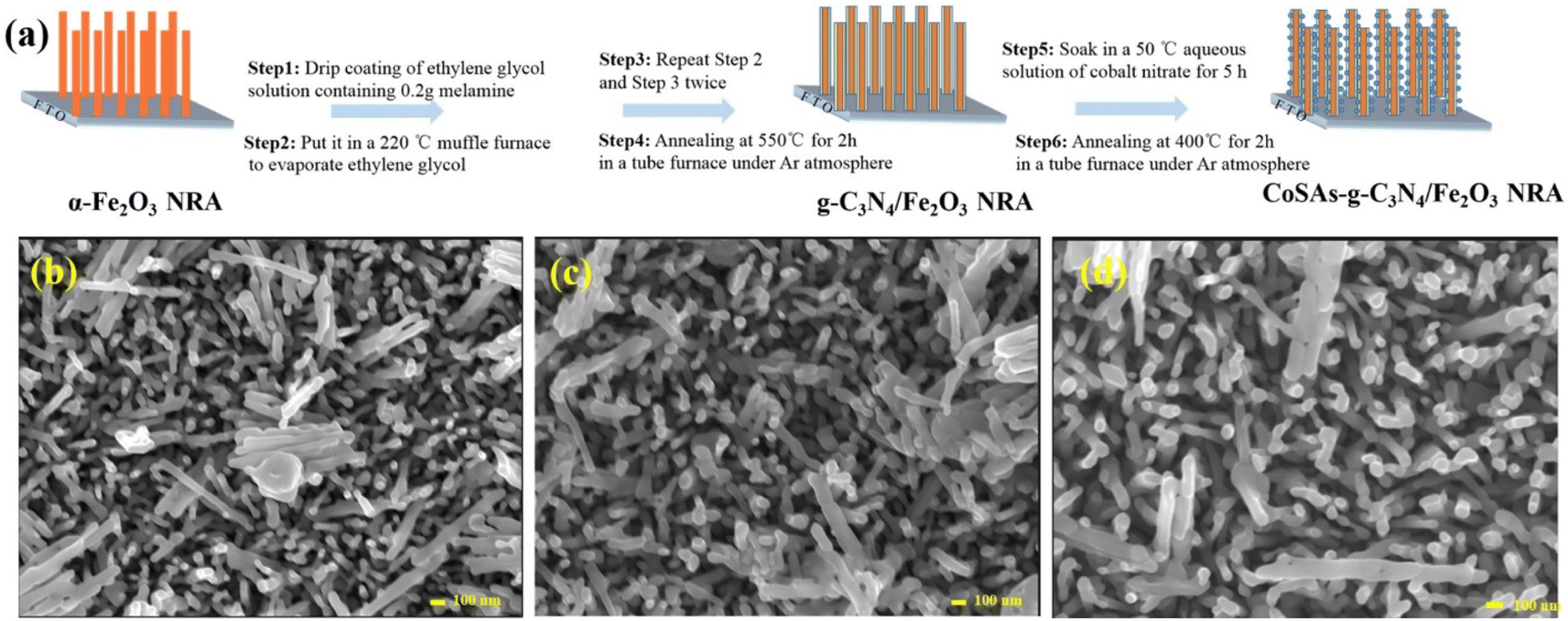 | ||
| Fig. 1 (a) Schematic of the CoSAs–g-C3N4/Fe2O3 NRA photoanode preparation process. Top-view SEM images of (b) α-Fe2O3; (c) g-C3N4/Fe2O3; (d) CoSAs–g-C3N4/Fe2O3. | ||
To confirm the presence of g-C3N4 and CoSAs, the aberration-corrected annular bright-field STEM (AC-ABF-STEM) imaging was performed on CoSAs–g-C3N4/Fe2O3. The AC-ABF-STEM image (Fig. 2a) revealed an ultra-thin layer of g-C3N4 surrounding α-Fe2O3 NR, forming a close interface, suggesting the formation of a heterojunction between g-C3N4 and α-Fe2O3.24,25 Additionally, numerous black dots corresponding to CoSAs were observed on g-C3N4 (marked by red circles), indicating the uniform dispersion of CoSAs without the presence of nanoparticles or clusters. The magnified AC-ABF-STEM images (Fig. 2b and c) revealed the poor crystallinity of the g-C3N4 layer, with an average thickness of ∼3 nm. The size of a single black dot corresponding to an isolated Co site was 0.15 nm. The high-resolution TEM (HRTEM) image (Fig. 2d) indicated a distinct interface structure with two lattice stripes. Particularly, the lattice stripe of 0.25 nm corresponded to the (110) crystal plane of α-Fe2O3.26–28 Another lattice stripe, observed within a thin layer of poor crystallinity, exhibited a lattice spacing of 0.33 nm, corresponding to the (002) crystal plane of g-C3N4.20 This strongly confirms that the ultra-thin layer with poor crystallization was g-C3N4, thereby validating the successful preparation of g-C3N4/Fe2O3 heterojunction. Moreover, TEM-EDS elemental mapping revealed a uniform distribution of Fe, O, C, N, and Co elements on NR (Fig. 2e), indicating the presence of the g-C3N4 layer and CoSAs. This confirms the successful formation of CoSAs–g-C3N4/Fe2O3 composite materials.
 | ||
| Fig. 2 (a)–(c) Atomic-resolution TEM images of CoSAs–g-C3N4/Fe2O3 NR (CoSAs are highlighted by red circles); (d) and (e) HRTEM image and EDS mapping of Co, Fe, O, C, and N for CoSAs–g-C3N4/Fe2O3 NR. | ||
To analyze the surface chemical states, we performed X-ray photoelectron spectroscopy (XPS) characterization on α-Fe2O3, g-C3N4/Fe2O3, and CoSAs–g-C3N4/Fe2O3. Fig. 3a–d show the XPS spectra of C 1s, N 1s, O 1s, and Co 2p, for CoSAs–g-C3N4/Fe2O3, respectively. The XPS spectra of C 1s (Fig. 3a) exhibited three peaks corresponding to C–C (284.8 eV), C–N (286.3 eV), and N–C![[double bond, length as m-dash]](https://www.rsc.org/images/entities/char_e001.gif) N (288.4 eV).20 The N 1s spectrum (Fig. 3b) featured two peaks at 399.7 and 401.4 eV, corresponding to N–(C)3 and C–NHx,20 respectively. These results from the C 1s and N 1s spectra indicate the successful loading of g-C3N4 on the α-Fe2O3 surface, resulting in the formation of a g-C3N4/Fe2O3 heterostructure. The O 1s spectrum (Fig. 3c) exhibited three peaks at around 529.8, 531.5, and 533.1 eV, which were assigned to the Fe–O bond,10 oxygen vacancies within the α-Fe2O3 structure,29 and surface hydroxyl groups, respectively.30 The Fe 2p spectrum (Fig. S3†) featured two peaks at 724.4 and 710.6 eV, corresponding to Fe 2p1/2 and Fe 2p3/2, respectively, along with two satellite peaks at 732.7 and 718.2 eV, consistent with the reported values for Fe3+ in Fe2O3.31 Additionally, the Fe 2p3/2 peak can be deconvoluted into three peaks at 712.2, 710.6, and 709.6 eV, indicating the characteristics of Fe3+. The Co 2p spectra (Fig. 3d) exhibited two main peaks corresponding to Co 2p3/2 (781.5 eV) and Co 2p1/2 (796.5 eV),15 along with satellite peaks, suggesting the successful anchoring of CoSAs on g-C3N4. Notably, after the loading of CoSAs and g-C3N4, the Fe 2p, O 1s, and N 1s peaks slightly shifted to higher binding energies, suggesting interactions between CoSAs, g-C3N4, and α-Fe2O3 (Fig. S4†).14
N (288.4 eV).20 The N 1s spectrum (Fig. 3b) featured two peaks at 399.7 and 401.4 eV, corresponding to N–(C)3 and C–NHx,20 respectively. These results from the C 1s and N 1s spectra indicate the successful loading of g-C3N4 on the α-Fe2O3 surface, resulting in the formation of a g-C3N4/Fe2O3 heterostructure. The O 1s spectrum (Fig. 3c) exhibited three peaks at around 529.8, 531.5, and 533.1 eV, which were assigned to the Fe–O bond,10 oxygen vacancies within the α-Fe2O3 structure,29 and surface hydroxyl groups, respectively.30 The Fe 2p spectrum (Fig. S3†) featured two peaks at 724.4 and 710.6 eV, corresponding to Fe 2p1/2 and Fe 2p3/2, respectively, along with two satellite peaks at 732.7 and 718.2 eV, consistent with the reported values for Fe3+ in Fe2O3.31 Additionally, the Fe 2p3/2 peak can be deconvoluted into three peaks at 712.2, 710.6, and 709.6 eV, indicating the characteristics of Fe3+. The Co 2p spectra (Fig. 3d) exhibited two main peaks corresponding to Co 2p3/2 (781.5 eV) and Co 2p1/2 (796.5 eV),15 along with satellite peaks, suggesting the successful anchoring of CoSAs on g-C3N4. Notably, after the loading of CoSAs and g-C3N4, the Fe 2p, O 1s, and N 1s peaks slightly shifted to higher binding energies, suggesting interactions between CoSAs, g-C3N4, and α-Fe2O3 (Fig. S4†).14
 | ||
| Fig. 3 High-resolution XPS spectra of (a) C 1s; (b) N 1s; (c) O 1s; (d) Co 2p, for CoSAs–g-C3N4/Fe2O3. | ||
Furthermore, X-ray absorption near-edge structure (XANES) analysis was performed to investigate the oxidation state and coordination structure of Co atoms in CoSAs–g-C3N4/Fe2O3. The XANES spectra of CoSAs–g-C3N4/Fe2O3 (Fig. 4a) indicated the unique oxidation state of Coδ+ (0 < δ < 2), which can be supported by the linear combination fitting (LCF) result (Fig. S5†). The extended X-ray absorption fine structure (EXAFS) spectra of CoSA–g-C3N4/Fe2O3 (Fig. 4b) exhibited a single dominant peak at 1.5 Å, corresponding to the first coordination shell of Co–N. Notably, the weaker peak intensity of the CoSAs–g-C3N4/Fe2O3 spectrum compared with CoPc suggested a lower Co–N coordination value and inferior crystal properties.32 Additionally, the absence of the characteristic Co–Co bond length (∼2.1 Å) in Co foils within CoSAs–g-C3N4/Fe2O3, indicated the lack of Co nanoparticles, consistent with atomic-resolution TEM data (Fig. 2a–c) and XRD pattern (Fig. S2†). The coordination of Co sites was further investigated through EXAFS curve fitting analysis (Fig. 4c), confirming that each Co atom was coordinated with 4.1 ± 0.2 N atoms at the first shell and 1.1 ± 0.4 C atoms at second shell according to the fitting results (Fig. S6 and Table S1†). Notably, unlike the reference samples, a strong peak of Co–N coordination in the wavelet transforms (WT) of Co K-edge EXAFS oscillations (Fig. 4d), directly confirmed the presence of CoSAs on the g-C3N4/Fe2O3 substrate. All results obtained from atomic-resolution STEM, HRTEM, XPS, and XANES confirmed the successful preparation of the CoSAs–g-C3N4/Fe2O3 photoanode.
 | ||
| Fig. 4 (a) XANES spectra; (b) R-space Co K-edge EXAFS spectra; (c) EXAFS R-space fitting curve; (d) WT-EXAFS signals of Co foil, CoO, CoPc and CoSAs–g-C3N4/Fe2O3. | ||
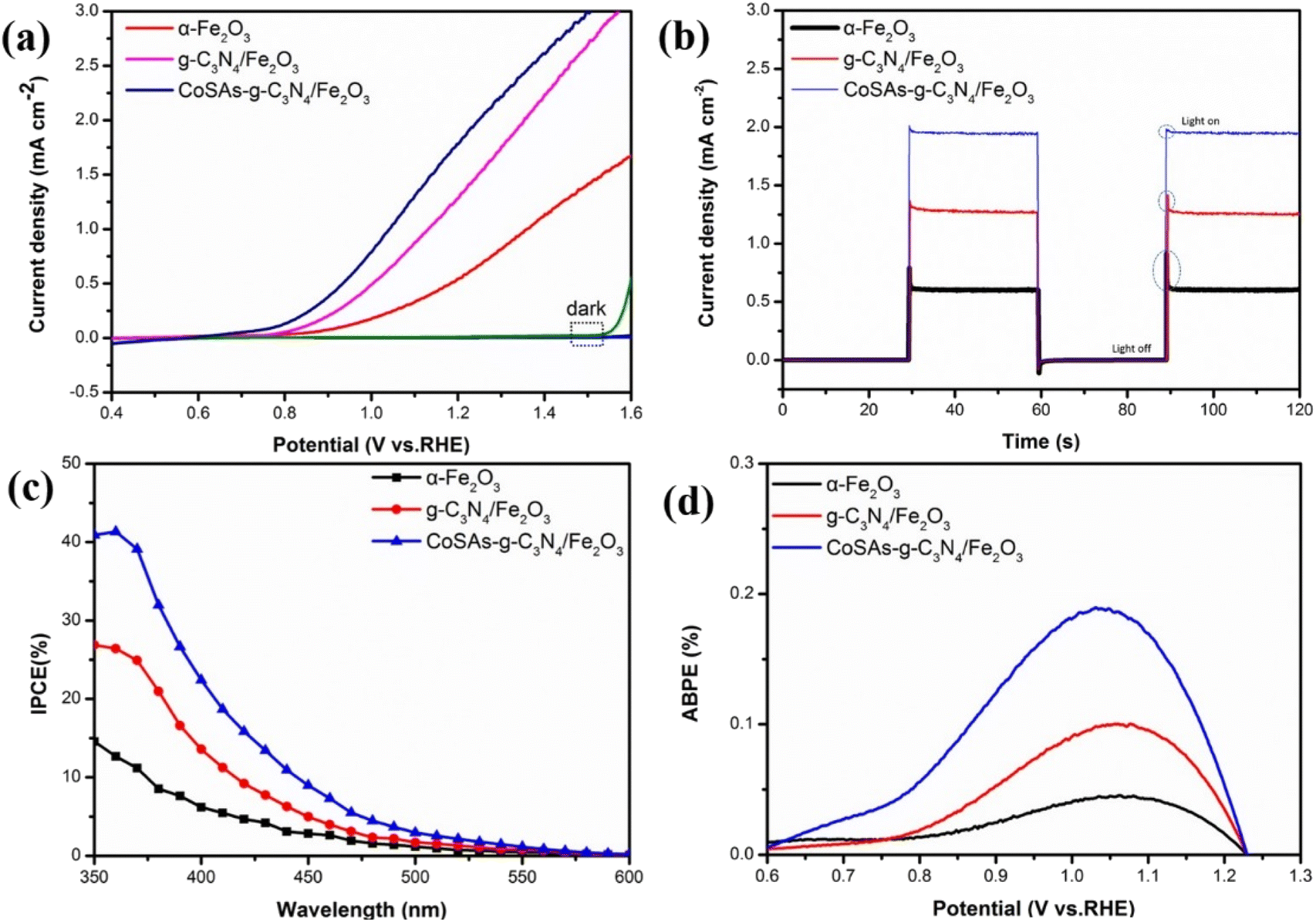
The PEC water oxidation properties of the obtained photoanodes were measured using a three-electrode system. The linear sweep voltammetry (LSV) curves (Fig. 5a) revealed that pure α-Fe2O3 exhibited a photocurrent density of 0.59 mA cm−2 at 1.23 VRHE with an initial potential of 0.775 VRHE. Upon coupling α-Fe2O3 with g-C3N4, the photocurrent density of g-C3N4/Fe2O3 increased to 1.4 mA cm−2, accompanied by a negative initial potential shift of 37 mV. This shift suggests that the formed g-C3N4/Fe2O3 heterojunction promoted rapid charge transfer. Moreover, after anchoring CoSAs on g-C3N4, CoSAs–g-C3N4/Fe2O3 exhibited a photocurrent density of 1.93 mA cm−2. This indicates that CoSAs provided additional active sites for water oxidation, which effectively inhibited surface charge recombination and promoted interfacial charge transfer. Compared with g-C3N4/Fe2O3, the initial potential of CoSAs–g-C3N4/Fe2O3 (0.58 VRHE) decreased by 158 mV, indicating a significant contribution from dispersed CoSAs to the acceleration of oxygen evolution reaction (OER) kinetics. This finding was consistent with transient photocurrent test results (Fig. 5b). α-Fe2O3 exhibited a large transient photocurrent spike owing to the significant occurrence of charge recombination in the bulk and surface of the material.33,34 The coupling of α-Fe2O3 with g-C3N4, significantly suppressed the transient peak. Additionally, the gradual increase in the photocurrent density of g-C3N4/Fe2O3 can be attributed to the built-in electric field generated by the g-C3N4/Fe2O3 heterojunction, which facilitated the directional separation of photogenerated charges.1,35,36 Compared with g-C3N4/Fe2O3, CoSAs–g-C3N4/Fe2O3 exhibited a smaller transient spike, which almost disappeared, while the photocurrent further increased. This phenomenon indicates that the dispersed CoSAs cocatalyst promoted sluggish water oxidation kinetics, thereby significantly facilitating charge transfer and separation. Furthermore, the incident photon-to-current efficiency (IPCE) of the sample was calculated to evaluate its solar energy conversion efficiency. At a wavelength (λ) of 350 nm, α-Fe2O3, g-C3N4/Fe2O3, and CoSAs–g-C3N4/Fe2O3 exhibited IPCE values of 14.5, 26.8, and 40.9%, respectively, indicating a gradually increasing trend (Fig. 5c). Regarding the influence of light collection efficiency, charge separation efficiency, and injection efficiency on IPCE, the IPCE result strongly confirmed the synergistic effect of g-C3N4 and CoSAs in enhancing the light absorption, promoting charge separation, and improving hole injection efficiency of the pure α-Fe2O3 photoanode. The applied bias photon-to-current conversion efficiency (ABPE) results exhibited a similar trend (Fig. 5d). The α-Fe2O3 photoanode exhibited an ABPE value of 0.05% at 1.06 VRHE, which was significantly lower than those of g-C3N4/Fe2O3 (0.1% at 1.05 VRHE) and CoSAs–g-C3N4/Fe2O3 (0.18% at 1.03 VREH). The increase in ABPE values and the negative shift of the peak position indicated that the introduction of g-C3N4 and CoSAs can enable efficient charge separation in the low potential range, facilitating better energy conversion.1,14,22
 | ||
| Fig. 5 (a) LSV curves; (b) transient photocurrent measurements at 1.23 VRHE; (c) IPCE curves; (d) ABPE curves of α-Fe2O3, g-C3N4/Fe2O3, and CoSAs–g-C3N4/Fe2O3 photoanodes. | ||
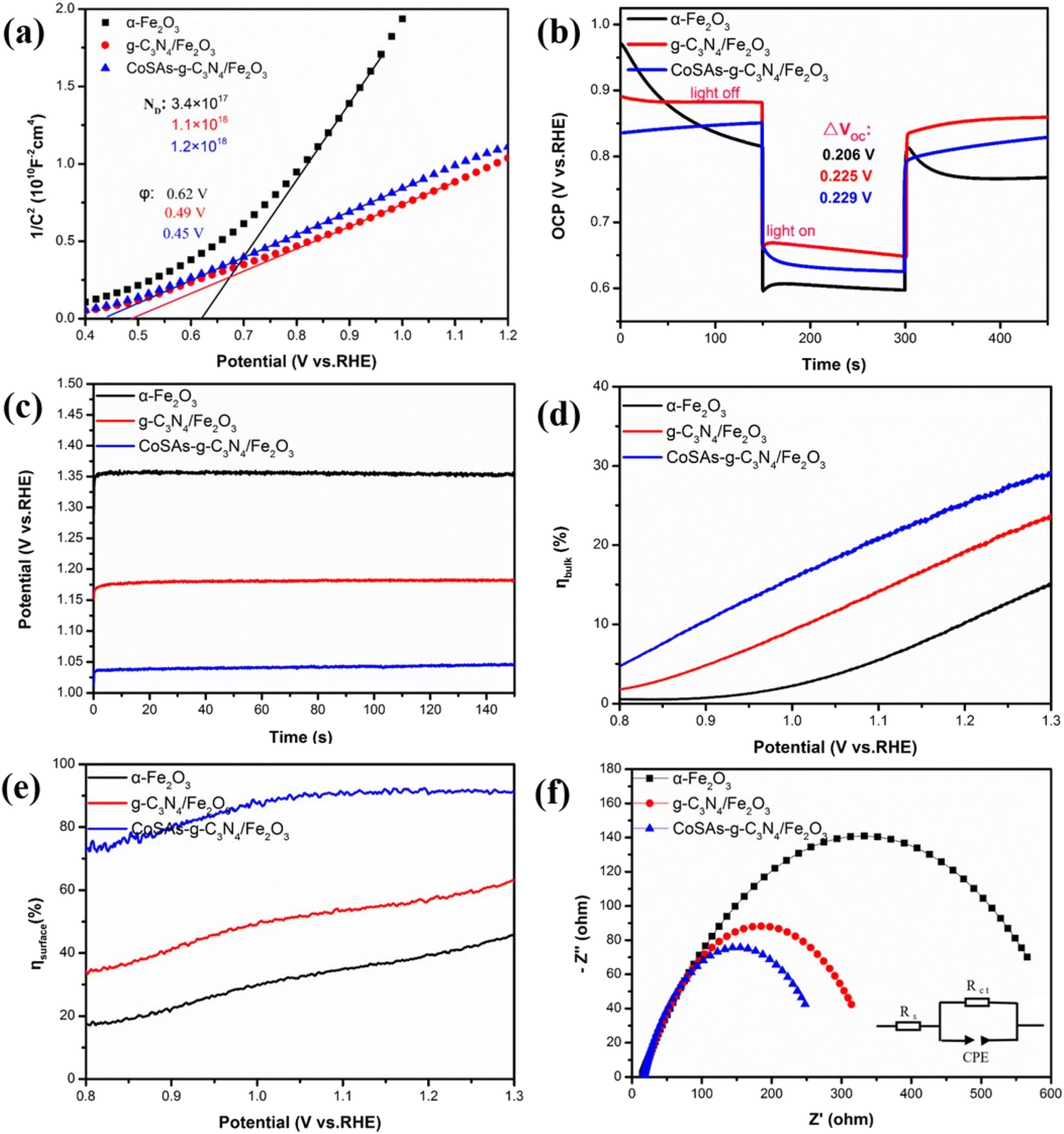
The Mott–Schottky (M–S) plots, open circuit photovoltage (OCP) curves, and the potential required to generate a photocurrent density of 1 mA cm−2 were used to further investigate the influence of g-C3N4 and Co SAs on the PEC performance of α-Fe2O3. All photoanodes exhibited positive slopes, reflecting their n-type semiconductor characteristics (Fig. 6a).29,37 The α-Fe2O3, g-C3N4/Fe2O3, and CoSAs–g-C3N4/Fe2O3 photoelectrodes featured carrier densities of 3.4 × 10¹⁷, 1.1 × 10¹⁸, and 1.2 × 1018 cm−3, respectively. The increase in carrier concentration can be attributed to the surface modifications introduced by g-C3N4 as a heterojunction and CoSAs as a cocatalyst. These modifications significantly inhibited the recombination process of the bulk and surface charge carriers, facilitating the easier release and injection of more photogenerated holes into the electrolyte. Consequently, this led to improved charge separation efficiency and water oxidation performance. Additionally, the successive negative shift in the flat potential of α-Fe2O3 (0.62 VRHE), g-C3N4/Fe2O3 (0.49 VRHE), and CoSAs–g-C3N4/Fe2O3 (0.45 VRHE) indicated increased photovoltage, enhanced charge mobility, and improved water oxidation kinetics. Generally, a higher the ΔVOC (ΔVOC = OCPdark − OCPlight) indicates a stronger inherent electric field and a greater driving force for carrier separation.14,38 The α-Fe2O3, g-C3N4/Fe2O3, and CoSAs–g-C3N4/Fe2O3 photoanodes exhibited ΔVOC values of 0.206, 0.225, and 0.229 VRHE, respectively (Fig. 6b). The g-C3N4/Fe2O3 composite exhibited a higher ΔVOC than α-Fe2O3, indicating the formation of a strong built-in electric field resulting from the coupling of g-C3N4 and α-Fe2O3. This increased band bending provided an additional driving force for charge separation and effectively suppressed carrier recombination.39,40 Upon the introduction of CoSAs, the ΔVOC of CoSAs–g-C3N4/Fe2O3 further increased, indicating that CoSAs can further reduce carrier recombination and promote charge separation. The potentials required for α-Fe2O3, g-C3N4/Fe2O3, and CoSAs–g-C3N4/Fe2O3 to generate a photocurrent density of 1 mA cm−2 were 1.36, 1.17, and 1.03 VRHE, respectively (Fig. 6c). The significant decrease in overpotential indicated that the synergistic effect of the g-C3N4/Fe2O3 heterojunction and CoSAs can improve charge separation and injection efficiency, thereby significantly enhancing PEC water oxidation performance. To accurately assess the effect of g-C3N4 and CoSAs on the PEC properties of α-Fe2O3, the bulk charge separation efficiency (ηbulk) and surface charge separation efficiency (ηsurface) were independently calculated. This calculation was performed using the LSV data and the integrated photocurrent density (Jabs) (Fig. S7†) with Na2SO3 as the sacrificial agent. The ηbulk of pure α-Fe2O3 considerably increased from 11.5% to 20.6% with the introduction of g-C3N4, and further increased to 26.3% with CoSAs (Fig. 6d). Notably, both the incorporation of g-C3N4 as a heterojunction and the introduction of CoSAs as a cocatalyst can reduce the recombination of bulk photogenerated electron–hole pairs and promote charge separation, with the construction of heterojunctions playing a more critical role. Additionally, the ηsurface of α-Fe2O3 significantly increased from 40.3% to 58.8% with the introduction of g-C3N4 and further to 91.3% with the addition CoSAs. The highest charge injection efficiency achieved through the introduction of CoSAs can be attributed to the dispersed CoSAs, which effectively extracted holes from the surface of g-C3N4/Fe2O3 and provided more active sites to deoxidize water (Fig. 6e).41 Electrochemical impedance spectroscopy (EIS) was used to examine the charge transfer resistance at the photoanode interface. All Nyquist plots were fitted using the equivalent circuit (inset of Fig. 6f). The relevant fitting results are summarized in Table S2.† The g-C3N4/Fe2O3 composite (337.2 Ω) exhibited a significantly lower charge transfer resistance than α-Fe2O3 (634.3 Ω), indicating the heterojunction interface facilitated rapid interfacial charge transfer (Fig. 6f). With the anchoring of CoSA cocatalysts, CoSAs–g-C3N4/Fe2O3 exhibited the lowest resistance (269.9 Ω), signifying the role of the CoSA cocatalyst in improving the efficiency of surface charge transfer and hole injection. All these results confirm that the synergistic effect of CoSAs and heterojunction fabrication can significantly improve the overall carrier density, charge separation, and injection efficiency, leading to a significant enhancement in PEC water splitting performance.
 | ||
| Fig. 6 (a) M–S plots; (b) OCP transient decay curves; (c) potential (VRHE) versus time for the photoelectrodes at 1 mA cm−2; (d) ηbulk; (e) ηsurface; (f) EIS of α-Fe2O3, g-C3N4/Fe2O3, CoSAs–g-C3N4/Fe2O3 photoanodes. | ||
Stability is a vital parameter for evaluating the performance of photoelectrodes. Therefore, we investigated the water oxidation stability of CoSAs–g-C3N4/Fe2O3, and the relevant results are shown in Fig. 7. After continuous irradiation for 3.8 h (Fig. 7a), the photoanode exhibited good stability and acceptable attenuation of photocurrent density. The XRD (Fig. 7b), SEM (Fig. 7c), and HRTEM (Fig. 7d) images of the photoanodes remained consistent with those obtained before testing. This indicates that the crystal structure and array morphology of the surface CoSAs–g-C3N4/Fe2O3 electrode remained unchanged.
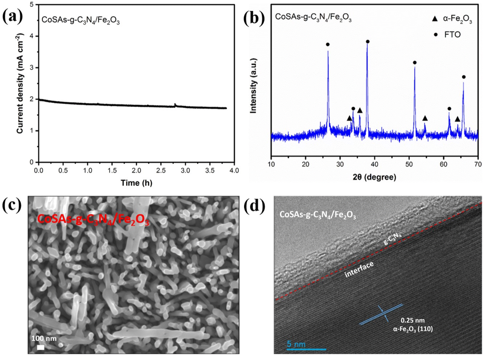 | ||
| Fig. 7 (a) Photocurrent density stability of CoSAs–g-C3N4/Fe2O3 photoanodes at 1.23 VRHE; (b) XRD pattern; (c) SEM; (d) HRTEM of CoSAs–g-C3N4/Fe2O3 photoanodes after long-term stability tests. | ||
To elucidate possible charge transfer pathways and water oxidation mechanisms, the band positions of α-Fe2O3 and g-C3N4 were accurately examined. The energy band location of CoSAs–g-C3N4/Fe2O3 was calculated and plotted based on the results of UV-Vis spectroscopy (Fig. S8†) and UPS. The α-Fe2O3 and g-C3N4 samples exhibited band gap values of 2.07 and 2.64 eV, respectively (Fig. 8a). The UPS results of the α-Fe2O3 and g-C3N4 samples are illustrated in Fig. 8b and c. The work function (Φ) indicated the energy of the Fermi level regarding the vacuum level, while |EVBM| was calculated using eqn (S5) and (S6).† The α-Fe2O3 and g-C3N4 samples featured Φ values of 3.82, and 2.67 eV, respectively. Additionally, α-Fe2O3 and g-C3N4 exhibited |EVBM| values of 5.49 and 4.88 eV, respectively. Moreover, the inset in Fig. 8b and c shows the band alignment diagrams derived from α-Fe2O3 and g-C3N4, respectively. With the use of the band arrangement diagrams obtained from α-Fe2O3 and g-C3N4, Fig. 8d illustrates the schematic of the CoSAs–g-C3N4/Fe2O3 band location indicating the formation of a typical type-II heterojunction between α-Fe2O3 and g-C3N4. Therefore, the potential water oxidation mechanism of CoSAs–g-C3N4/Fe2O3 is illustrated in Fig. 8e. Upon contact between α-Fe2O3 and g-C3N4, band bending occurred, thereby establishing the Fermi level equilibrium, and forming heterojunction. Upon illumination, the photoelectrons of α-Fe2O3 and g-C3N4 were excited from the valence band (VB) to the conduction band (CB), respectively. In the presence of the built-in electric field formed at the interface between α-Fe2O3 and g-C3N4, photogenerated charges underwent rapid separation and transfer, effectively inhibiting electron–hole pairs recombination. Photoelectrons transitioned from the CB of g-C3N4 to the CB of α-Fe2O3 and then traveled through the external circuit to the Pt electrode, facilitating the reduction of water to produce hydrogen. Furthermore, the VB holes in α-Fe2O3 rapidly migrated to the VB of g-C3N4, where they were further captured by the highly dispersed CoSAs. Owing to the strong oxidation of these photogenerated holes, Coδ+ can be oxidized to Co2+/Co3+, which oxidized water to produce oxygen. Moreover, the reduction of Co2+/Co3+ ions to Coδ+, enabled the efficient separation of photogenerated electrons and holes.
 | ||
| Fig. 8 (a) Calculated band gap values (based on UV-Vis absorption spectra) of α-Fe2O3 and g-C3N4. Ultra UV photoelectron spectroscopy (UPS) and work function of (b) α-Fe2O3 and (c) g-C3N4; (d) energy band diagram of the g-C3N4/Fe2O3 heterojunction; (e) Schematic illustration of electron–hole separation of CoSAs–g-C3N4/Fe2O3 photoanode for PEC water splitting. | ||
Conclusions
We successfully prepared a novel CoSAs–g-C3N4/Fe2O3 photoanode with excellent PEC performance by coupling g-C3N4 with α-Fe2O3 and anchoring CoSAs on g-C3N4. Compared with pure α-Fe2O3, the g-C3N4/Fe2O3 heterostructure significantly inhibited the recombination of photogenerated charges. The incorporation of CoSAs into the photoanode structure further improved the charge separation efficiency and injection efficiency of α-Fe2O3, thereby promoting reaction kinetics. The synergistic effect of Co SAs and g-C3N4 contributed to the excellent PEC performance of CoSAs–g-C3N4/Fe2O3. The optimized CoSAs–g-C3N4/Fe2O3 photoanode exhibited a maximum photocurrent density of 1.93 mAcm−2 at 1.23 VRHE, which was 3.22 times that of pure α-Fe2O3, with a negative shift in initial potential by 195 mV. This study provides a promising approach for developing efficient and stable single atom photoanodes for PEC water splitting applications.Data availability
All experimental details and characterisation data can be found in the ESI.†Author contributions
J. W., L. J. and W. L. designed the experiment and wrote the manuscript. J. W., B. H., H. D. and N. W. conducted the experiments. J. W., X. D., M. L. and H. C. analysed data. All authors discussed the results at all stages and participated in the development of the manuscript.Conflicts of interest
The authors declare no conflict of interest.Acknowledgements
The authors are grateful for the financial support from the Specialized Research Fund for the Doctoral Program of Higher Education of China (Grant No. ZKNUC2020042), Key Scientific and Technological Project of Henan Province (Grant No. 232102240044, 242102230101), Natural Science Foundation Project of Henan Province (Grant No. 232300420400).References
- Z. Peng, Y. Su, I. Ennaji, A. Khojastehnezhad and M. Siaj, Chem. Eng. J., 2023, 477, 147082 CrossRef CAS.
- W. Bai, H. Li, G. Peng, J. Wang, A. Li and P. F.-X. Corvini, Appl. Catal., B, 2024, 352, 124023 CrossRef CAS.
- R. T. Gao, L. Liu, Y. Li, Y. Yang, J. He, X. Liu, X. Zhang, L. Wang and L. Wu, Proc. Natl. Acad. Sci. U. S. A., 2023, 120, e2300493120 CrossRef CAS.
- R. T. Gao, T. N. Nguyen, T. Nakajima, J. He, X. Liu, X. Zhang, L. Wang and L. Wu, Sci. Adv., 2023, 9, eade4589 CrossRef.
- L. Wang, J. Zhu and X. Liu, ACS Appl. Mater. Interfaces, 2019, 11, 22272–22277 CrossRef CAS PubMed.
- J.-B. Pan, X. Liu, B.-H. Wang, Y.-A. Chen, H.-Y. Tan, J. Ouyang, W. Zhou, S. Shen, L. Chen, C.-T. Au and S.-F. Yin, Appl. Catal., B, 2022, 315, 121526 CrossRef CAS.
- L. K. Dhandole, T. S. Koh, P. Anushkkaran, H.-S. Chung, W.-S. Chae, H. H. Lee, S. H. Choi, M. Cho and J. S. Jang, Appl. Catal., B, 2022, 315, 121538 CrossRef CAS.
- J. Bai, R.-T. Gao, X. Guo, J. He, X. Liu, X. Zhang and L. Wang, Chem. Eng. J., 2022, 448, 137602 CrossRef CAS.
- H. Chai, S. Wang, X. Wang, J. Ma and J. Jin, ACS Catal., 2022, 12, 3700–3709 CrossRef CAS.
- H. Chai, L. Gao, P. Wang, F. Li, G. Hu and J. Jin, Appl. Catal., B, 2022, 305, 121011 CrossRef CAS.
- Y. Wang, X. Huang and Z. Wei, Chin. J. Catal., 2021, 42, 1269–1286 CrossRef CAS.
- L. Zhang, R. Long, Y. Zhang, D. Duan, Y. Xiong, Y. Zhang and Y. Bi, Angew. Chem., Int. Ed., 2020, 59, 6224–6229 CrossRef CAS PubMed.
- T. L. L. Doan, D. C. Nguyen, S. Prabhakaran, D. H. Kim, D. T. Tran, N. H. Kim and J. H. Lee, Adv. Funct. Mater., 2021, 31, 2100233 CrossRef CAS.
- Y. Sun, H. Li, Y. Hu, J. Wang, A. Li and P. F.-X. Corvini, Appl. Catal., B, 2024, 340, 123269 CrossRef CAS.
- X. Liu, Y. Deng, L. Zheng, M. R. Kesama, C. Tang and Y. Zhu, ACS Catal., 2022, 12, 5517–5526 CrossRef CAS.
- D. A. Kuznetsov, Z. Chen, P. V. Kumar, A. Tsoukalou, A. Kierzkowska, P. M. Abdala, O. V. Safonova, A. Fedorov and C. R. Muller, J. Am. Chem. Soc., 2019, 141, 17809–17816 CrossRef CAS.
- P. Liao, J. A. Keith and E. A. Carter, J. Am. Chem. Soc., 2012, 134, 13296–13309 CrossRef CAS PubMed.
- J. Büker, X. Huang, J. Bitzer, W. Kleist, M. Muhler and B. Peng, ACS Catal., 2021, 11, 7863–7875 CrossRef.
- Y. Zheng, Q. Ruan, J. Ren, X. Guo, Y. Zhou, B. Zhou, Q. Xu, Q. Fu, S. Wang and Y. Huang, Appl. Catal., B, 2023, 323, 122170 CrossRef CAS.
- S. Xin, X. Ma, J. Lu, G. Zhang, S. Huo, M. Gao, P. Xu, W. Liu and W. Fu, Appl. Catal., B, 2023, 323, 122174 CrossRef CAS.
- J. Wu, M. Qi, G. Wang, B. Yu, C. Liu, W. Hou and W. Liu, ACS Sustainable Chem. Eng., 2020, 8, 5200–5208 CrossRef CAS.
- J. Wu, M. Meng, X. D. Du, M. Li, L. Jin and W. Liu, Inorg. Chem., 2024, 63, 6192–6201 CrossRef CAS PubMed.
- S.-S. Yi, J.-M. Yan and Q. Jiang, J. Mater. Chem. A, 2018, 6, 9839–9845 RSC.
- G. Yang, Y. Li, H. Lin, X. Ren, D. Philo, Q. Wang, Y. He, F. Ichihara, S. Luo, S. Wang and J. Ye, Small Methods, 2020, 4, 202000577 Search PubMed.
- X. Zhou, T. Wang, L. Zhang, S. Che, H. Liu, S. Liu, C. Wang, D. Su and Z. Teng, Appl. Catal., B, 2022, 316, 121614 CrossRef CAS.
- Z. Masoumi, M. Tayebi, M. Kolaei, A. Tayyebi, H. Ryu, J. I. Jang and B. K. Lee, ACS Appl. Mater. Interfaces, 2021, 13, 39215–39229 CrossRef CAS PubMed.
- J. Wu, P. Huang, H. Fan, G. Wang and W. Liu, ACS Appl. Mater. Interfaces, 2020, 12, 30304–30312 CrossRef CAS PubMed.
- T. Wang, X. Long, S. Wei, P. Wang, C. Wang, J. Jin and G. Hu, ACS Appl. Mater. Interfaces, 2020, 12, 49705–49712 CrossRef CAS.
- J. Lin, X. Han, S. Liu, Y. Lv, X. Li, Y. Zhao, Y. Li, L. Wang and S. Zhu, Appl. Catal., B, 2023, 320, 121947 CrossRef CAS.
- K. Kang, C. Tang, J. H. Kim, W. J. Byun, J. H. Lee, M. H. Lee, H. Zhang and J. S. Lee, ACS Catal., 2023, 13, 7002–7012 CrossRef CAS.
- S.-S. Yi, B.-R. Wulan, J.-M. Yan and Q. Jiang, Adv. Funct. Mater., 2019, 29, 1801902–1801910 CrossRef.
- X. Liu, L. Zheng, C. Han, H. Zong, G. Yang, S. Lin, A. Kumar, A. R. Jadhav, N. Q. Tran, Y. Hwang, J. Lee, S. Vasimalla, Z. Chen, S. G. Kim and H. Lee, Adv. Funct. Mater., 2021, 31, 2100547 CrossRef CAS.
- F. Li, J. Li, L. Gao, Y. Hu, X. Long, S. Wei, C. Wang, J. Jin and J. Ma, J. Mater. Chem. A, 2018, 6, 23478–23485 RSC.
- R. Chong, Y. Du, Z. Chang, Y. Jia, Y. qiao, S. Liu, Y. Liu, Y. Zhou and D. Li, Appl. Catal., B, 2019, 250, 224–233 CrossRef CAS.
- Y. Zhang, Y. Huang, S. S. Zhu, Y. Y. Liu, X. Zhang, J. J. Wang and A. Braun, Small, 2021, 17, 2100320 CrossRef CAS.
- J. Liu, W. Chen, Q. Sun, Y. Zhang, X. Li, J. Wang, C. Wang, Y. Yu, L. Wang and X. Yu, ACS Appl. Energy Mater., 2021, 4, 2864–2872 CrossRef CAS.
- S. Zhang, Z. Liu, D. Chen and W. Yan, Appl. Catal., B, 2020, 277, 119197 CrossRef CAS.
- J. H. Kim and J. S. Lee, Adv. Mater., 2019, 31, 1806938 CrossRef.
- G. Yang, S. Li, X. Wang, B. Ding, Y. Li, H. Lin, D. Tang, X. Ren, Q. Wang, S. Luo and J. Ye, Appl. Catal., B, 2021, 297, 120268 CrossRef CAS.
- H. Zhang, D. Li, W. J. Byun, X. Wang, T. J. Shin, H. Y. Jeong, H. Han, C. Li and J. S. Lee, Nat. Commun., 2020, 11, 4622 CrossRef.
- R. T. Gao, J. Zhang, T. Nakajima, J. He, X. Liu, X. Zhang, L. Wang and L. Wu, Nat. Commun., 2023, 14, 2640 CrossRef CAS PubMed.
Footnote |
| † Electronic supplementary information (ESI) available: Supplementary figures; LSV, XRD, XPS, EXAFS, PL, UV-Vis, the calculated current density flux and integrated current density (Jabs), dielectric loss, and leakage current density, EXAFS fitting parameters at the Co K-edge for various samples, fitting data of the EIS. See DOI: https://doi.org/10.1039/d4sc03442b |
| This journal is © The Royal Society of Chemistry 2024 |