 Open Access Article
10-Dibenzothiophenyl-9,9-diphenylacridane-based multiple resonance emitters for high-efficiency narrowband green OLEDs with CIE y > 0.7 at high doping concentrations†
Rui
Zhong
ab,
Mengyu
Wang
ab,
Xingdong
Wang
a,
Shumeng
Wang
 a,
Shiyang
Shao
*ac and
Lixiang
Wang
 *ab
*ab
aState Key Laboratory of Polymer Physics and Chemistry, Changchun Institute of Applied Chemistry, Chinese Academy of Sciences, Changchun, Jilin 130022, China. E-mail: lixiang@ciac.ac.cn
bSchool of Applied Chemistry and Engineering, University of Science and Technology of China, Hefei, Anhui 230026, China
cState Key Laboratory of Marine Resource Utilization in South China Sea, School of Materials Science and Engineering, Hainan University, Haikou, Hainan 570228, China. E-mail: ssyang@hainanu.edu.cn
First published on 16th July 2024
Abstract
Multiple resonance emitters are attractive for high-color-purity organic light-emitting diodes (OLEDs) because of their unique narrowband emissions; however, they are typically used at low doping concentrations (≤15 wt%) due to aggregation-caused quenching and spectral broadening induced by planar molecular skeletons. Here, we report two multiple resonance emitters (BThPAc-1 and BThPAc-2) consisting of a 10-dibenzothiophenyl-9,9-diphenylacridane segment for efficient narrowband green emission at high doping concentrations. The dibenzothiophenyl-9,9-diphenylacridane segment contains two carbon-bridged phenyl rings as steric groups to inhibit intermolecular aggregation and a dibenzothiophene unit to extend conjugation and red-shift the emission to the green region. The resultant emitters exhibit narrowband emissions that peaked at 509–510 nm with a full width at half-maximum (FWHM) of 32 nm in 1 wt% doping films, which are maintained at less than 35 nm even in neat films. Remarkably, OLEDs employing the emitters reveal pure-green electroluminescence with a maximum external quantum efficiency of 20.3% and CIE coordinates of (0.18, 0.72) at 30 wt% doping concentration, which represents the best color coordinates for green multiple resonance OLEDs at high doping concentrations.
1 Introduction
Thermally activated delayed fluorescence (TADF) emitters are attractive for organic light-emitting diodes because of their capability to utilize triplet excitons by the reverse intersystem crossing (RISC) process without the use of noble metals. To realize the rapid RISC process, a small energy gap (ΔEST) between singlet (S1) and triplet (T1) states is required for TADF emitters.1–4 In this regard, TADF emitters are generally designed based on twisted donor–acceptor (D–A) architecture to minimize the overlap between the highest occupied molecular orbital (HOMO) and lowest unoccupied molecular orbital (LUMO) to reduce ΔEST.5–7 However, such D–A type TADF emitters are accompanied by strong intramolecular charge transfer (ICT) character with large structural relaxation in excited states, leading to a large Stokes shift and a broad emission spectrum with full width at half-maximum (FWHM) larger than 70 nm, unfavourable for application in high-resolution displays requiring pure red/green/blue (R/G/B) emissions.8–10Recently, multiple resonance thermally activated delayed fluorescence (MR-TADF) emitters have attracted much attention of researchers because of their narrowband emissions that can overcome the drawbacks of broad emission bands for D–A type TADF emitters.11–15 In general, MR-TADF emitters are composed of polycyclic aromatic hydrocarbon (PAH) skeletons embedded with electron-rich atoms (nitrogen, oxygen, sulfur, and selenium) and electron-deficient atoms/groups (boron/carbonyl) with opposite electronic effects.16–27 This arrangement of heteroatoms induces the atomic separation of the HOMO and LUMO with non-bonding orbitals, resulting in reduced vibration relaxation and narrowband emissions with FWHM less than 40 nm.28–33 By rational design of molecular structures, full-color MR-TADF emitters with emission covering the whole visible light range and EQE > 30% have been developed.34–39 Despite this progress, MR emitters still suffer from severe aggregation-caused quenching (ACQ) and spectral broadening at high doping concentrations due to their planar structure and strong intermolecular aggregation, making them always used at relatively low-concentration doped films (≤15 wt%).40–51 Although much attention has been paid to the introduction of bulky groups into MR-TADF for providing steric hindrance to reduce intermolecular interaction,52–63 it is still challenging to develop MR emitters with green emission (CIE y value > 0.70) that are insensitive to doping concentrations.64–69 For instance, 5,11-diphenyl-5,11-dihydroindolo[3,2-b]carbazole (ICz)-based emitters (BN-ICz-1 and BN-ICz-2)50 have been reported to exhibit reduced vibration and a small FWHM of 21 nm, giving green emission at 522 nm with CIE coordinates of (0.24, 0.73) in OLED devices. Nevertheless, these emitters worked at low doping concentrations of 1–5 wt%. Similarly, MR emitters with the nitrogen atom fused at different positions49 (BN-TP-N4) have been reported to show high-color-purity green emission with a CIE y value of 0.70 at 3 wt% doping concentration but deteriorating to CIE y < 0.70 at 5 wt% concentration. Actually, green MR emitters with CIE y > 0.70 at high doping concentrations (>15 wt%) are not reported in the literature so far.
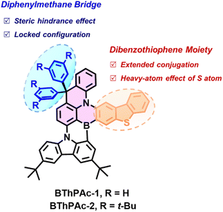
Here, we report two green MR-TADF emitters (BThPAc-1 and BThPAc-2) consisting of a 10-dibenzothiophenyl-9,9-diphenylacridane-based B, N-doped polycyclic skeleton for efficient narrowband OLEDs with high color-purity even at high doping concentration (Fig. 1). This molecular design utilizes two carbon-bridged phenyl rings of a dibenzothiophenyl-9,9-diphenylacridane segment as to provide steric hindrance to suppress aggregation of the polycyclic skeleton, and a dibenzothiophene unit to extend conjugation and red-shift the emission to the green region. As a result, the emitters BThPAc-1 and BThPAc-2 exhibit green emissions at 509–510 nm with a narrow FWHM of 32 nm at 1 wt% doping concentration, which are maintained at 515–520 nm with FWHM of 34–35 nm even in neat films. OLED devices based on the emitters exhibit green electroluminescence with an emission peak at 514 nm, FWHM of 33 nm, CIE coordinates of (0.16, 0.71) and a maximum EQE of 26.5% at a low doping concentration of 3 wt%. Remarkably, at a high doping concentration of 30 wt%, the OLEDs still maintain the high color purity with CIE coordinates of (0.18, 0.72) for a maximum EQE of 20.3%, representing the best color coordinates for green MR-TADF OLEDs at high doping concentrations (>15 wt%, Table S7†).
2 Results and discussion
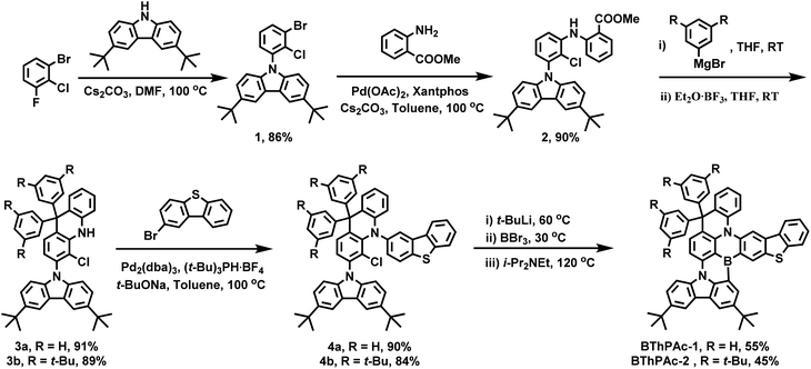
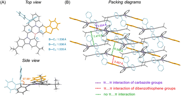
The synthesis of BThPAc-1 and BThPAc-2 is outlined in Scheme 1. 1-Bromo-2-chloro-3-fluorobenzene was used as a starting material which underwent nucleophilic substitution with 3,6-bis(tert-butyl)-carbazole and the Buchwald coupling reaction with methyl 2-aminobenzoate to afford the ester intermediate 2. Subsequently, 2 was reacted with phenylmagnesium bromide or 3,5-di-tert-butylphenylmagnesium bromide and then with boron trifluoride etherate to form the key acridan intermediates 3a and 3b, followed by coupling with 2-bromodibenzothiophene to afford the chloride precursors 4a and 4b. The precursors were lithiated and underwent intramolecular electrophilic borylation with boron tribromide and N,N-diisopropylethylamine to give the desired products BThPAc-1 and BThPAc-2 in yields of 40–60%. To investigate the role of the fused thiophene moiety, the MR emitter without the dibenzothiophene moiety (PAc) was also synthesized from 3a through the same synthetic procedure except by using bromobenzene instead of 2-bromodibenzothiophene to form the chloride precursor. The synthesized compounds were identified by 1H and 13C NMR spectra and mass spectra (Fig. S13–S34†). Thermogravimetric analysis shows that both BThPAc-1 and BThPAc-2 exhibit good thermal stability with decomposition temperatures (5% weight) above 400 °C, suitable for the preparation of OLED devices by the vacuum evaporation process. The electrochemical properties of BThPAc-1 and BThPAc-2 were characterized by cyclic voltammetry, which show reversible oxidation waves with onset potentials (Eoxonset) at 0.55 and 0.49 V, and irreversible reduction waves with onset potentials (Eredonset) at −1.98 and −1.99 V, respectively. According to the oxidation and reduction onset potentials, HOMO/LUMO levels were determined to be −5.35/−1.98 eV and −5.29/−2.02 eV for BThPAc-1 and BThPAc-2, respectively.To investigate the crystallographic structure of the emitters, single crystals are grown by slowly evaporating the solvent of a solution of the samples in a dichloromethane/n-hexane mixture (1/2, v/v) at 20 °C to form needle-like crystals of BThPAc-1 that can be characterized by synchrotron radiation X-ray diffraction. As shown in Fig. 2, the geometry of BThPAc-1 exhibits a quasi-planar configuration for the polycyclic skeleton with typical B–C, N–C and S–C bond lengths of 1.535–1.536 Å, 1.395–1.431 Å and 1.739–1.754 Å, respectively. Remarkably, the two carbon-bridged phenyl groups are almost perpendicular to the polycyclic skeleton plane, providing steric hindrance for the central MR skeleton. In the packing model, a strong steric effect of the perpendicular phenyl groups forces two adjacent BThPAc-1 molecules to stack in a head-to-head and tail-to-tail pattern. Two types of π⋯π interactions are observed which belong to two carbazole groups with a distance of 3.554 Å and two dibenzothiophene groups with a distance of 3.457 Å, respectively, corresponding to quasi-dimers. However, other π-groups are staggered due to steric hindrance of the carbon-bridged phenyl rings, leading to enlarged distances over 6.0 Å and effectively suppressed intermolecular interactions.
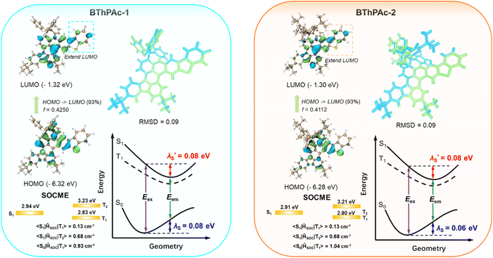
To gain insight into photophysical properties of two emitters, density functional theory (DFT) and time-dependent DFT (TD-DFT) calculations are carried out at the M062x/def2-SVP level to calculate their optimized ground and excited state geometries and frontier molecular orbital (FMO) distributions. To accurately determine excited state energy levels for the emitters, a second-order approximate coupled-cluster with singles and doubles (SCS-CC2) model is also employed using the cc-pVDZ basis set.70 As depicted in Fig. 3 and S1–S4,† HOMOs are mainly localized on nitrogen atoms and their ortho-/para-positions of the surrounding phenyl rings, while LUMOs are localized on boron atoms and their ortho-/para-positions, corresponding to atomically separated FMO distributions for typical MR emitters. Notably, compared to PAc without the dibenzothiophenyl moiety, BThPAc-1 and BThPAc-2 exhibit extended HOMO and LUMO distributions to peripheral dibenzothiophenyl moieties, indicating larger conjugation of the polycyclic skeleton. Consequently, S1 energy levels of BThPAc-1 and BThPAc-2 (2.91–2.94 eV) are lower than that of PAc (3.08 eV). The ΔEST values for BThPAc-1 and BThPAc-2 are 0.11–0.12 eV, which are small enough to promote the RISC process. Meanwhile, the emitters exhibit a small root mean square deviation (RMSD) of 0.09 and a small reorganization energy of 0.14–0.16 eV between S0 and S1 states, indicating a small structural change upon excitation. It is noted that BThPAc-1 and BThPAc-2 have considerable SOC matrix elements (SOCME) between singlet states (Sn) and triplet states (Tn) (0.13–0.68 for S1–Tn (n = 1–2) and 0.91–1.04 for S0–T1). Such SOC matrix element values are much larger than those of PAc without the dibenzothiophenyl moiety (0.13–0.14 for S1–Tn (n = 1–2) and 0.73 for S0–T1), indicating that the sulfur atom in the dibenzothiophenyl moiety can play a crucial role in enhancing spin–orbital coupling.
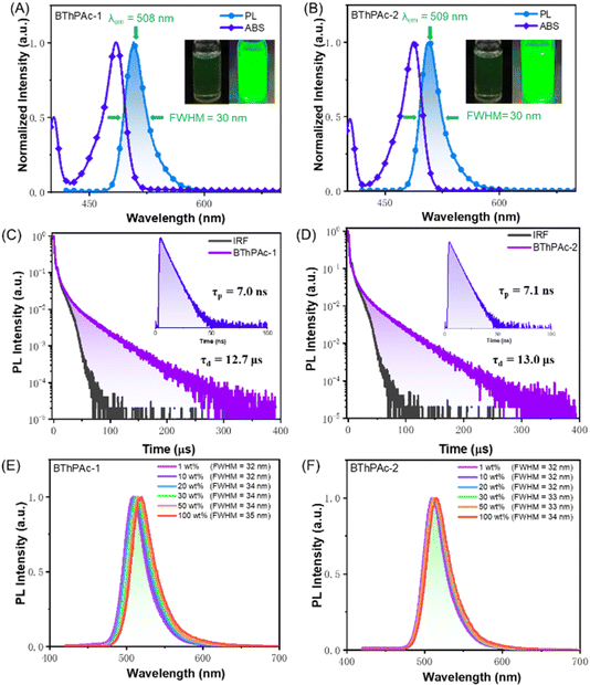
To investigate photophysical properties, UV-vis absorption and photoluminescence spectra of BThPAc-1 and BThPAc-2 in dilute toluene solution (10−5 M) were measured. As shown in Fig. 4(A) and (B), BThPAc-1 and BThPAc-2 show two absorption bands at 404–405 nm and 485–488 nm in toluene, which are assigned to π–π* transitions of polycyclic skeletons and intramolecular charge-transfer (ICT) transitions, respectively (Table 1). While for PL spectra, BThPAc-1 and BThPAc-2 exhibit intense and sharp emissions at 508 and 509 nm in toluene, respectively, corresponding to a small Stokes shift of 21–23 nm typical for the multi-resonance emitters. Compared to PAc with an emission maximum of 484 nm, the emission peaks for BThPAc-1 and BThPAc-2 are red-shifted by 24–25 nm, consistent with their extended conjugation and reduced S1 energy level, as predicted by TD-DFT calculations. It is noted that the FWHM values for BThPAc-1 and BThPAc-2 (∼30 nm) are the same as that of PAc, indicating that extension of conjugation barely affects the narrowband emission characteristics for the MR skeleton. PL spectra of the emitters in solvents with different polarities show a slight red-shift and broadening as the solvent polarity increases, consistent with their short-range ICT characteristic. According to onsets of fluorescence and phosphorescence spectra at 77 K, the experimental S1/T1 state energy levels are 2.57/2.41 eV and 2.55/2.40 eV for BThPAc-1 and BThPAc-2, respectively, giving small ΔEST values of 0.15–0.16 eV. The PLQY for the emitters measured in doped films (5 wt% doping ratios in mCP) are 88–89%, which are higher than that of PAc (PLQY = 83%). To demonstrate the effect of bridged phenyl rings on aggregation behaviors in the solid state, the dependence of PL spectra of the emitters on the doping concentration is investigated. As shown in Fig. 4(E) and (F), BThPAc-1 exhibits narrowband green emission at 509 nm with an FWHM of 32 nm at a low concentration of 1 wt%. As the doping concentration gradually increases to 100 wt%, the emission band is red-shifted by 11 nm (from 509 to 520 nm), while the FWHM is slightly increased to 35 nm. For BThPAc-2 containing tert-butyl groups in two phenyl units, the red shift of emission is decreased by 5 nm (from 510 to 515 nm), and the FWHM value is broadened by only 2 nm (from 32 to 34 nm). These results indicate that intermolecular interaction and aggregation-caused spectral broadening can be efficiently suppressed by incorporating two carbon-bridged phenyl units into the MR skeleton.
| λ abs [nm] | λ em [nm] | FWHMc[nm] | Φ PLQY | τ p/τde[ns μs−1] | k r [107 S−1] | k ISC [107 S−1] | k RISC [105 S−1] | S1/T1g[eV] | ΔESTh[eV] | |
|---|---|---|---|---|---|---|---|---|---|---|
| a Absorption peak measured in toluene solution (10−5 M). b Emission peak measured in toluene solution (10−5 M). c Full width at half maximum of the PL spectrum. d Photoluminescence quantum yield measured in doping films in mCP (5 wt%). e Prompt and delayed fluorescence lifetimes of doping films. f k r, kISC and kRISC represent the rate constants of radiative decay of S1, intersystem crossing from S1 to T1 and reverse intersystem crossing from T1 to S1. g Singlet (S1) and triplet (T1) state energy levels estimated from fluorescence and phosphorescence spectra. h Energy gap between S1 and T1. | ||||||||||
| BThPAc-1 | 485 | 508 | 30 | 0.88 | 7.0/12.7 | 9.0 | 4.3 | 1.1 | 2.57/2.41 | 0.16 |
| BThPAc-2 | 488 | 509 | 30 | 0.89 | 7.1/13.0 | 9.0 | 4.2 | 1.2 | 2.55/2.40 | 0.15 |
Transient PL decay spectra of BThPAc-1 and BThPAc-2 are shown in Fig. 4(C) and (D), which reveal both prompt fluorescence with lifetimes of 7.0–7.1 ns and delayed fluorescence with lifetimes in the range of 12.7–13.0 μs. As the temperature increases from 200 K to 300 K, the delayed components of two emitters increase corresponding to the thermally activated triplet-to-singlet up-conversion process. The ratios of delayed components are 30% and 32% for BThPAc-1 and BThPAc-2, respectively, giving rate constants of prompt fluorescence (kr), intersystem crossing (kISC) and kRISC of 0.9–1.0 × 10⁸, 4.2–4.3 × 10⁷ and 1.1–1.2 × 10⁵ for BThPAc-1 and BThPAc-2, respectively. Notably, kISC and kRISC for BThPAc-1 and BThPAc-2 are much larger than those of PAc (kISC = 1.5 × 10⁷ and kRISC = 0.6 × 10⁵), indicating that intersystem crossing between singlet and triplet states can be accelerated by the enhanced SOC.
To investigate electroluminescence properties of the two emitters, OLEDs with the configuration of indium tin oxide (ITO)/(1,1-bis[(di-4-tolylamino)phenyl]cyclohexane) (TAPC) (90 nm)/(tris(4-carbazolyl-9-ylphenyl)amine) (TCTA) (5 nm)/3,3′-bis(N-carbazolyl)-1,1′-biphenyl (mCBP) (5 nm)/2-(5-(4,6-diphenyl-1,3,5-triazin-2-yl)-2-methylphenyl)-1-phenyl-benzo[d]imidazole (BIZ-6Me-TRZ): 1–30 wt% emitter (30 nm)/(5-tri(m-pyrid-3-yl-phenyl)benzene) (TmPyPB) (45 nm)/LiF (1 nm)/Al (150 nm) were fabricated. The chemical structure and energy diagram of materials used for OLED devices are illustrated in Fig. 5(A) and (B), and the device performance is displayed in Fig. 5(C)–(E). As shown in Fig. 5(D), devices using 1 wt% BThPAc-1 and BThPAc-2 as emitters exhibit emission peaks at 512 and 511 nm, accompanied by FWHM of 34 and 33 nm, respectively, corresponding to Commission International de l'Eclairage (CIE) coordinates of (0.15, 0.70) and (0.14, 0.69) (Table 2). As the emitter concentration increases from 1 to 30 wt%, the emission peak shifts slightly from 511–512 nm to 517–518 nm, and the FWHMs are maintained at 33–34 nm, giving CIE coordinates of (0.19, 0.72) and (0.18, 0.72) for BThPAc-1 and BThPAc-2, respectively, which are the best color coordinates for green MR-TADF OLEDs at high doping concentrations (>15 wt%) (Table S7†).
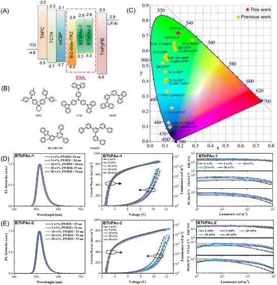 | ||
| Fig. 5 (A) Device configuration for BThPAc-1 and BThPAc-2. (B) Chemical structures of materials used for the devices. (C) CIE coordinates for BThPAc-1, BThPAc-2 and reported aggregation-resistant MR-TADF emitters at high doping concentrations (>15 wt%) (Table S7†). (D and E) OLED device performance for BThPAc-1 and BThPAc-2. | ||
| Doping concentration | V on [V] | L max [cd m−2] | CEmaxc [cd A−1] | PEmaxd [Im W−1] | EQEMax/100/1000e [%] | FWHMf [nm] | λ EL [nm] | CIEh (x, y) | |
|---|---|---|---|---|---|---|---|---|---|
| a Turn-on voltage at a luminance of 1 cd m−2. b Maximum luminance. c Maximum luminous efficiency. d Maximum power efficiency. e External quantum efficiency at maximum and at luminances of 100/1000 cd m−2. f Full-width at half-maximum at 1000 cd m−2. g EL maximum at 1000 cd m−2. h CIE coordinates at 1000 cd m−2. | |||||||||
| BThPAc-1 | 1 wt% | 2.67 | 28![[thin space (1/6-em)]](https://www.rsc.org/images/entities/char_2009.gif) 560 560 |
84.2 | 94.5 | 25.2/20.6/12.4 | 33.9 | 512 | 0.152, 0.702 |
| 3 wt% | 2.61 | 35![[thin space (1/6-em)]](https://www.rsc.org/images/entities/char_2009.gif) 443 443 |
87.9 | 98.7 | 24.8/22.8/15.5 | 34.3 | 516 | 0.171, 0.718 | |
| 10 wt% | 2.47 | 30![[thin space (1/6-em)]](https://www.rsc.org/images/entities/char_2009.gif) 277 277 |
79.6 | 93.1 | 22.0/20.9/15.2 | 34.5 | 517 | 0.181, 0.721 | |
| 20 wt% | 2.41 | 27![[thin space (1/6-em)]](https://www.rsc.org/images/entities/char_2009.gif) 497 497 |
69.5 | 83.6 | 19.0/18.5/14.0 | 34.7 | 518 | 0.187, 0.721 | |
| 30 wt% | 2.41 | 23![[thin space (1/6-em)]](https://www.rsc.org/images/entities/char_2009.gif) 844 844 |
62.7 | 75.5 | 17.0/16.9/12.9 | 34.4 | 518 | 0.191, 0.720 | |
| BThPAc-2 | 1 wt% | 2.68 | 26![[thin space (1/6-em)]](https://www.rsc.org/images/entities/char_2009.gif) 918 918 |
79.9 | 86.9 | 24.7/19.6/12.1 | 32.7 | 511 | 0.143, 0.693 |
| 3 wt% | 2.64 | 35![[thin space (1/6-em)]](https://www.rsc.org/images/entities/char_2009.gif) 737 737 |
89.9 | 100.9 | 26.5/22.0/14.4 | 32.7 | 514 | 0.157, 0.711 | |
| 10 wt% | 2.60 | 39![[thin space (1/6-em)]](https://www.rsc.org/images/entities/char_2009.gif) 268 268 |
91.2 | 106.8 | 25.8/24.1/16.4 | 33.1 | 516 | 0.171, 0.721 | |
| 20 wt% | 2.47 | 36![[thin space (1/6-em)]](https://www.rsc.org/images/entities/char_2009.gif) 141 141 |
80.0 | 95.0 | 22.4/21.6/15.5 | 33.0 | 517 | 0.174, 0.722 | |
| 30 wt% | 2.44 | 32![[thin space (1/6-em)]](https://www.rsc.org/images/entities/char_2009.gif) 504 504 |
72.6 | 85.8 | 20.3/20.0/14.6 | 32.9 | 517 | 0.176, 0.723 | |
The current density (J)–voltage (V)–luminance (L) and EQE–L–luminous efficiency (LE) characteristics of the OLEDs are shown in Fig. 5(D) and (E). The devices show low turn-on voltages (at a luminance of 1 cd m−2) of 2.4–2.7 V for BThPAc-1 and BThPAc-2. From the EQE–L characteristics of devices, it can be seen that the maximum EQEs are obtained at doping concentrations of 1 wt% and 3 wt%, which are 25.2% and 26.5% for BThPAc-1 and BThPAc-2, respectively, much higher than that of PAc (EQEmax = 20.7%) at the same doping concentration. At the practical luminance of 100 cd A−1, EQEs for BThPAc-1 and BThPAc-2 are maintained at 20.6% and 22.0%, respectively. The maximum luminous efficiencies (LEs) are 87.9 and 91.2 cd A−1 for BThPAc-1 and BThPAc-2, respectively, corresponding to maximum power efficiencies (PEs) of 98.7 and 106.8 Im W−1, respectively, which are about two-fold that of PAc (48.5 Im W−1). Importantly, BThPAc-1 and BThPAc-2 still exhibit high efficiency at a high doping concentration of 30 wt%, with the maximum EQE/LE/PE of 17.0%/62.7 cd A−1/75.5 Im W−1 for BThPAc-1 and 20.3%/72.6 cd A−1/85.8 Im W−1 for BThPAc-2. These results suggest that the DBDPA-based MR-TADF emitters can be an effective approach to realize high device efficiency for green emission with CIE y > 0.7 even at relatively high doping concentrations (>15 wt%).
3 Conclusions
In summary, we have developed two multiple resonance emitters (BThPAc-1 and BThPAc-2) containing a 10-dibenzothiophenyl-9,9-diphenylacridane-based B, N-doped polycyclic aromatic skeleton for efficient narrowband green emission at high doping concentrations. The two carbon-bridged phenyl rings of the dibenzothiophenyl-9,9-diphenylacridane segment provide steric hindrance to suppress the aggregation of the polycyclic skeleton, while the dibenzothiophene moiety could extend the conjugation to red-shift the emission to the green region. As a result, BThPAc-1 and BThPAc-2 exhibit green emissions of 509–510 nm with a narrow FWHM of 32 nm at 1 wt% doping concentration, which are maintained at 515–520 nm with narrow FWHMs of 34–35 nm as the doping concentration increases to 100 wt%. Meanwhile, the sulfur atom can enhance spin–orbital coupling by the heavy-atom effect, leading to the accelerated RISC process with a rate constant of 1.1–1.2 × 10⁵ s−1. OLED devices based on the emitters exhibit green emission with an emission peak at 514 nm, an FWHM of 33 nm and a maximum EQE of 26.5% at 3 wt% doping concentration. Importantly, the OLED devices still maintain the small FWHM of 33 nm and CIE coordinates of (0.18, 0.72), together with a high maximum EQE of 20.3% even at a doping concentration of 30 wt%, which is remarkable for green MR-TADF emitters with CIE y > 0.7 at high doping concentrations. These findings provide a facile and effective molecular design strategy for the development of aggregation-resistant multi-resonance emitters to realize efficient narrowband green emissions in wide doping concentration ranges.Data availability
The data supporting this article have been included as part of the ESI.†Author contributions
Rui Zhong synthesized the emitters and characterized the photophysical property. Mengyu Wang and Shumeng Wang fabricated and characterized the OLED devices. Xingdong Wang and Shiyang Shao provided guidance on synthesis and photophysical characterization. Rui Zhong and Shiyang Shao wrote the manuscript. L. W. supervised and directed this study.Conflicts of interest
There are no conflicts to declare.Acknowledgements
The authors acknowledge financial support from the National Natural Science Foundation of China (52122309, 52073282, 21975247, and 52261135541), the CAS-Croucher Funding Scheme for Joint Laboratories, the Innovational Fund for Scientific and Technological Personnel of Hainan Province (KJRC2023C09), the Open Project of State Key Laboratory of Supramolecular Structure and Materials (sklssm2024024), Start-up Scientific Research Foundation from Hainan University (KYQD(ZR)22174). The authors also acknowledge the staff of the BL17B beamline of National Facility for Protein Science in Shanghai (NFPS) at the Shanghai Synchrotron Radiation Facility for assistance in crystal structure data collection and the Network and Computing Center, Changchun Institute of Applied Chemistry, Chinese Academy of Sciences for help with theoretical calculations.References
- A. Endo, K. Sato, K. Yoshimura, T. Kai, A. Kawada, H. Miyazaki and C. Adachi, Appl. Phys. Lett., 2011, 98, 083302 CrossRef.
- R. K. Konidena and J. Y. Lee, Chem. Rec., 2019, 19, 1499 CrossRef CAS PubMed.
- H. Uoyama, K. Goushi, K. Shizu, H. Nomura and C. Adachi, Nature, 2012, 492, 234 CrossRef CAS PubMed.
- Z. Yang, Z. Mao, Z. Xie, Y. Zhang, S. Liu, J. Zhao, J. Xu, Z. Chi and M. P. Aldred, Chem. Soc. Rev., 2017, 46, 915 RSC.
- L.-S. Cui, A. J. Gillett, S.-F. Zhang, H. Ye, Y. Liu, X.-K. Chen, Z.-S. Lin, E. W. Evans, W. K. Myers, T. K. Ronson, H. Nakanotani, S. Reineke, J.-L. Bredas, C. Adachi and R. H. Friend, Nat. Photonics, 2020, 14, 636 CrossRef CAS.
- Y. Liu, C. Li, Z. Ren, S. Yan and M. R. Bryce, Nat. Rev. Mater., 2018, 3, 18020 CrossRef CAS.
- W. Yuan, H. Yang, C. Duan, X. Cao, J. Zhang, H. Xu, N. Sun, Y. Tao and W. Huang, Chem, 2020, 6, 1998 CAS.
- Y. Im, M. Kim, Y. J. Cho, J.-A. Seo, K. S. Yook and J. Y. Lee, Chem. Mater., 2017, 29, 1946 CrossRef CAS.
- F. Santoro, A. Lami, R. Improta, J. Bloino and V. Barone, J. Chem. Phys., 2008, 128, 224311 CrossRef PubMed.
- M. Y. Wong and E. Zysman-Colman, Adv. Mater., 2017, 29, 1605444 CrossRef PubMed.
- T. Hatakeyama, K. Shiren, K. Nakajima, S. Nomura, S. Nakatsuka, K. Kinoshita, J. Ni, Y. Ono and T. Ikuta, Adv. Mater., 2016, 28, 2777 CrossRef CAS PubMed.
- H. J. Kim and T. Yasuda, Adv. Opt. Mater., 2022, 10, 2201714 CrossRef CAS.
- S. Madayanad Suresh, D. Hall, D. Beljonne, Y. Olivier and E. Zysman-Colman, Adv. Funct. Mater., 2020, 30, 1908677 CrossRef CAS.
- K. R. Naveen, P. Palanisamy, M. Y. Chae and J. H. Kwon, Chem. Commun., 2023, 59, 3685 RSC.
- S. Oda, B. Kawakami, R. Kawasumi, R. Okita and T. Hatakeyama, Org. Lett., 2019, 21, 9311 CrossRef CAS PubMed.
- F. Chen, L. Zhao, X. Wang, Q. Yang, W. Li, H. Tian, S. Shao, L. Wang, X. Jing and F. Wang, Sci. China: Chem., 2021, 64, 547 CrossRef CAS.
- D. Hall, S. M. Suresh, P. L. dos Santos, E. Duda, S. Bagnich, A. Pershin, P. Rajamalli, D. B. Cordes, A. M. Z. Slawin, D. Beljonne, A. Köhler, I. D. W. Samuel, Y. Olivier and E. Zysman-Colman, Adv. Opt. Mater., 2019, 8, 1901627 CrossRef.
- T. Hua, L. Zhan, N. Li, Z. Huang, X. Cao, Z. Xiao, S. Gong, C. Zhou, C. Zhong and C. Yang, Chem. Eng. J., 2021, 426, 131169 CrossRef CAS.
- Q. Li, Y. Wu, X. Wang, Q. Yang, J. Hu, R. Zhong, S. Shao and L. Wang, Chem.–Eur. J., 2022, 28, e202104214 CrossRef CAS PubMed.
- Q. Li, Y. Wu, Q. Yang, S. Wang, S. Shao and L. Wang, ACS Appl. Mater. Interfaces, 2022, 14, 49995 CrossRef CAS PubMed.
- H. Min, I. S. Park and T. Yasuda, Angew. Chem., Int. Ed., 2021, 60, 7643 CrossRef CAS PubMed.
- M. Nagata, H. Min, E. Watanabe, H. Fukumoto, Y. Mizuhata, N. Tokitoh, T. Agou and T. Yasuda, Angew. Chem., Int. Ed., 2021, 60, 20280 CrossRef CAS PubMed.
- W. Ning, H. Wang, S. Gong, C. Zhong and C. Yang, Sci. China: Chem., 2022, 65, 1715 CrossRef CAS.
- I. S. Park, H. Min and T. Yasuda, Angew. Chem., Int. Ed., 2022, 61, e202205684 CrossRef CAS PubMed.
- I. S. Park, M. Yang, H. Shibata, N. Amanokura and T. Yasuda, Adv. Mater., 2022, 34, 2107951 CrossRef CAS PubMed.
- X. Wu, J. W. Huang, B. K. Su, S. Wang, L. Yuan, W. Q. Zheng, H. Zhang, Y. X. Zheng, W. Zhu and P. T. Chou, Adv. Mater., 2022, 34, 2105080 CrossRef CAS PubMed.
- Y. Yuan, X. Tang, X. Y. Du, Y. Hu, Y. J. Yu, Z. Q. Jiang, L. S. Liao and S. T. Lee, Adv. Opt. Mater., 2019, 7, 1801536 CrossRef.
- S. Oda, B. Kawakami, Y. Yamasaki, R. Matsumoto, M. Yoshioka, D. Fukushima, S. Nakatsuka and T. Hatakeyama, J. Am. Chem. Soc., 2022, 144, 106 CrossRef CAS PubMed.
- S. Oda, T. Sugitani, H. Tanaka, K. Tabata, R. Kawasumi and T. Hatakeyama, Adv. Mater., 2022, 34, 2201778 CrossRef CAS PubMed.
- Y. Xu, Z. Cheng, Z. Li, B. Liang, J. Wang, J. Wei, Z. Zhang and Y. Wang, Adv. Opt. Mater., 2020, 8, 1902142 CrossRef CAS.
- M. Yang, I. S. Park and T. Yasuda, J. Am. Chem. Soc., 2020, 142, 19468 CrossRef CAS PubMed.
- M. Yang, S. Shikita, H. Min, I. S. Park, H. Shibata, N. Amanokura and T. Yasuda, Angew. Chem., Int. Ed., 2021, 60, 23142 CrossRef CAS PubMed.
- Y. Zhang, D. Zhang, T. Huang, A. J. Gillett, Y. Liu, D. Hu, L. Cui, Z. Bin, G. Li, J. Wei and L. Duan, Angew. Chem., Int. Ed., 2021, 60, 20498 CrossRef CAS PubMed.
- Y. C. Cheng, X. C. Fan, F. Huang, X. Xiong, J. Yu, K. Wang, C. S. Lee and X. H. Zhang, Angew. Chem., Int. Ed., 2022, 61, e202212575 CrossRef CAS PubMed.
- Y. X. Hu, J. Miao, T. Hua, Z. Huang, Y. Qi, Y. Zou, Y. Qiu, H. Xia, H. Liu, X. Cao and C. Yang, Nat. Photonics, 2022, 16, 803 CrossRef CAS.
- Y. Kondo, K. Yoshiura, S. Kitera, H. Nishi, S. Oda, H. Gotoh, Y. Sasada, M. Yanai and T. Hatakeyama, Nat. Photonics, 2019, 13, 678 CrossRef CAS.
- Q. Wang, Y. Xu, T. Yang, J. Xue and Y. Wang, Adv. Mater., 2023, 35, 2205166 CrossRef CAS.
- Y. Zhang, J. Wei, L. Wang, T. Huang, G. Meng, X. Wang, X. Zeng, M. Du, T. Fan, C. Yin, D. Zhang and L. Duan, Adv. Mater., 2023, 35, 2209396 CrossRef CAS PubMed.
- Y. Zou, J. Hu, M. Yu, J. Miao, Z. Xie, Y. Qiu, X. Cao and C. Yang, Adv. Mater., 2022, 34, 2201442 CrossRef CAS PubMed.
- S. Cai, G. S. M. Tong, L. Du, G. K. So, F. F. Hung, T. L. Lam, G. Cheng, H. Xiao, X. Chang, Z. X. Xu and C. M. Che, Angew. Chem., Int. Ed., 2022, 61, e202213392 CrossRef CAS PubMed.
- X. Fan, X. Hao, F. Huang, J. Yu, K. Wang and X. Zhang, Adv. Sci., 2023, 10, 2303504 CrossRef CAS PubMed.
- X.-C. Fan, K. Wang, Y.-Z. Shi, Y.-C. Cheng, Y.-T. Lee, J. Yu, X.-K. Chen, C. Adachi and X.-H. Zhang, Nat. Photonics, 2023, 17, 280 CrossRef CAS.
- Y. Hu, J. Miao, C. Zhong, Y. Zeng, S. Gong, X. Cao, X. Zhou, Y. Gu and C. Yang, Angew. Chem., Int. Ed., 2023, 62, e202302478 CrossRef CAS PubMed.
- J. Liu, Y. Zhu, T. Tsuboi, C. Deng, W. Lou, D. Wang, T. Liu and Q. Zhang, Nat. Commun., 2022, 13, 4876 CrossRef CAS PubMed.
- Y. Liu, X. Xiao, Z. Huang, D. Yang, D. Ma, J. Liu, B. Lei, Z. Bin and J. You, Angew. Chem., Int. Ed., 2022, 61, e202210210 CrossRef CAS PubMed.
- X. F. Luo, S. Q. Song, H. X. Ni, H. Ma, D. Yang, D. Ma, Y. X. Zheng and J. L. Zuo, Angew. Chem., Int. Ed., 2022, 61, e202209984 CrossRef CAS PubMed.
- S. Uemura, S. Oda, M. Hayakawa, R. Kawasumi, N. Ikeda, Y. T. Lee, C. Y. Chan, Y. Tsuchiya, C. Adachi and T. Hatakeyama, J. Am. Chem. Soc., 2023, 145, 1505 CrossRef CAS PubMed.
- J. Wang, N. Li, C. Zhong, J. Miao, Z. Huang, M. Yu, Y. X. Hu, S. Luo, Y. Zou, K. Li and C. Yang, Adv. Mater., 2023, 35, 2208378 CrossRef CAS PubMed.
- M. Wang, Z. Fu, R. Cheng, J. Du, T. Wu, Z. Bin, D. Wu, Y. Yang and J. Lan, Chem. Commun., 2023, 59, 5126 RSC.
- Q. Wang, Y. Xu, T. Huang, Y. Qu, J. Xue, B. Liang and Y. Wang, Angew. Chem., Int. Ed., 2023, 62, e202301930 CrossRef CAS PubMed.
- Y. Zhang, G. Li, L. Wang, T. Huang, J. Wei, G. Meng, X. Wang, X. Zeng, D. Zhang and L. Duan, Angew. Chem., Int. Ed., 2022, 61, e202202380 CrossRef CAS PubMed.
- G. Chen, J. Wang, W. C. Chen, Y. Gong, N. Zhuang, H. Liang, L. Xing, Y. Liu, S. Ji, H. L. Zhang, Z. Zhao, Y. Huo and B. Z. Tang, Adv. Funct. Mater., 2023, 33, 2211893 CrossRef CAS.
- B. Du, K. Zhang, P. Wang, X. Wang, S. Wang, S. Shao and L. Wang, J. Mater. Chem. C, 2023, 11, 9578 RSC.
- T. Fan, Y. Zhang, L. Wang, Q. Wang, C. Yin, M. Du, X. Jia, G. Li and L. Duan, Angew. Chem., Int. Ed., 2022, 61, e202213585 CrossRef CAS PubMed.
- L. Liang, C. Qu, X. Fan, K. Ye, Y. Zhang, Z. Zhang, L. Duan and Y. Wang, Angew. Chem., Int. Ed., 2024, 63, e202316710 CrossRef CAS PubMed.
- F. Liu, Z. Cheng, L. Wan, Z. Feng, H. Liu, H. Jin, L. Gao, P. Lu and W. Yang, Small, 2022, 18, 2106462 CrossRef CAS PubMed.
- J. Park, K. J. Kim, J. Lim, T. Kim and J. Y. Lee, Adv. Mater., 2022, 34, 2108581 CrossRef CAS PubMed.
- Y. K. Qu, D. Y. Zhou, F. C. Kong, Q. Zheng, X. Tang, Y. H. Zhu, C. C. Huang, Z. Q. Feng, J. Fan, C. Adachi, L. S. Liao and Z. Q. Jiang, Angew. Chem., Int. Ed., 2022, 61, e202201886 CrossRef CAS PubMed.
- L. Xiaofeng, Z. Dongdong, D. Lian and Z. Yuewei, Front. Chem., 2023, 11, 1198404 CrossRef PubMed.
- J. Bian, S. Chen, L. Qiu, R. Tian, Y. Man, Y. Wang, S. Chen, J. Zhang, C. Duan, C. Han and H. Xu, Adv. Mater., 2022, 34, 2110547 CrossRef CAS PubMed.
- Y. Chang, Y. Wu, K. Zhang, S. Wang, X. Wang, S. Shao and L. Wang, Dyes Pigm., 2023, 220, 111678 CrossRef CAS.
- H. J. Cheon, S. J. Woo, S. H. Baek, J. H. Lee and Y. H. Kim, Adv. Mater., 2022, 34, 2207416 CrossRef CAS PubMed.
- Y. N. Hu, X. C. Fan, F. Huang, Y. Z. Shi, H. Wang, Y. C. Cheng, M. Y. Chen, K. Wang, J. Yu and X. H. Zhang, Adv. Opt. Mater., 2022, 11, 2202267 CrossRef.
- F. Huang, X. C. Fan, Y. C. Cheng, H. Wu, Y. Z. Shi, J. Yu, K. Wang, C. S. Lee and X. H. Zhang, Mater. Horiz., 2022, 9, 2226 RSC.
- P. Jiang, J. Miao, X. Cao, H. Xia, K. Pan, T. Hua, X. Lv, Z. Huang, Y. Zou and C. Yang, Adv. Mater., 2022, 34, 2106954 CrossRef CAS PubMed.
- X. F. Luo, H. X. Ni, X. Liang, D. Yang, D. Ma, Y. X. Zheng and J. L. Zuo, Adv. Opt. Mater., 2023, 11, 2203002 CrossRef CAS.
- Y. Xu, C. Li, Z. Li, Q. Wang, X. Cai, J. Wei and Y. Wang, Angew. Chem., Int. Ed., 2020, 59, 17442 CrossRef CAS PubMed.
- Y. Zhang, J. Wei, D. Zhang, C. Yin, G. Li, Z. Liu, X. Jia, J. Qiao and L. Duan, Angew. Chem., Int. Ed., 2022, 61, e202113206 CrossRef CAS PubMed.
- N. Peethani, N. Y. Kwon, C. W. Koh, S. H. Park, J. M. Ha, M. J. Cho, H. Y. Woo, S. Park and D. H. Choi, Adv. Opt. Mater., 2023, 12, 2301217 CrossRef.
- A. Pershin, D. Hall, V. Lemaur, J. C. Sancho-Garcia, L. Muccioli, E. Zysman-Colman, D. Beljonne and Y. Olivier, Nat. Commun., 2019, 10, 597 CrossRef CAS PubMed.
Footnote |
| † Electronic supplementary information (ESI) available. CCDC 2350022. For ESI and crystallographic data in CIF or other electronic format see DOI: https://doi.org/10.1039/d4sc03705g |
| This journal is © The Royal Society of Chemistry 2024 |

