
 Open Access Article
 This Open Access Article is licensed under a
 Creative Commons Attribution 3.0 Unported Licence
Thermal-integration in photoelectrochemistry for fuel and heat co-generation†
Evan F
Johnson
and
Sophia
Haussener
 *
*
Laboratory of Renewable Energy Science and Engineering, EPFL, Station 9, 1015 Lausanne, Switzerland. E-mail: sophia.haussener@epfl.ch; Tel: +41 21 693 3878
First published on 6th August 2024
Abstract
Photoelectrochemical (PEC) devices for hydrogen generation typically use liquid water as reactant and operate under natural sunlight (irradiation of 1 kW m−2). However, devices can instead use the vapor in ambient air as reactant, include solar irradiation concentration, and consider the co-generation of low- and high-temperature heat. This expands the possible PEC device designs to include everything from vapor-fed PEC devices to complex designs featuring solar concentration and beam splitting to better utilize the entire solar spectrum. In this work, fundamental heat and mass transfer limits for liquid- and vapor-fed designs using solar concentration are shown. Four representative system configurations are studied, featuring both liquid and vapor supplied PEC devices, solar concentration on the PEC and on a cavity type solar receiver, and beam splitting. The systems produce hydrogen, low temperature heat collected from the PEC, and (in some cases) high temperature heat (at 500 °C) from a solar receiver under concentrated irradiation. Systems are optimized for band gaps and optical cutoffs and compared on an energy and exergy basis. For systems not utilizing solar concentration on the PEC, vapor-fed designs are shown to be optimized at higher band gaps than liquid-fed designs. In systems using concentration, overall exergetic efficiencies are generally lower due to optical losses and the unusable diffuse fraction of radiation, but they have the benefit of producing high-temperature thermal energy as a useful product. Tuning these systems for the optimal balance of both hydrogen and heat may be critical in industrial processes using both products, such as in solar fuels or green ammonia production.
1 Introduction
The vast majority of photoelectrochemical (PEC) devices for water splitting to produce hydrogen use liquid water as the feedstock.1,2 Some recent studies have looked into using vapor in ambient air as reactant in electrolyzers, which eliminates active water usage, freezing related issues for low ambient temperature operation, and the cost and complexity of the high-purity water delivery systems currently required.3–6 Without the need for liquid water, vapor-fed PEC devices may open up possibilities for low cost and decentralized hydrogen production. Another possible operational choice for PEC devices is whether to use concentrated solar radiation, which can yield high hydrogen production rates while minimizing the PEC area required.7,8 A better utilization of the solar spectrum has been considered in thermally-integrated PEC devices,7 where low-energy photons and the thermalized heat are used to support the catalytic reactions. This approach can be pushed to even better spectral utilization by considering PEC fuel and heat co-generation systems. (Spectral) beam splitting can be considered for this approach. Systems utilizing concentrated radiation present the possibility of co-generating hydrogen and high-temperature heat, which is used in numerous industrial applications, including drying, food processing, or residential heating. Furthermore, high-temperature heat can be utilized in the conversion of hydrogen gas into higher value products such as solar-derived fuels and green ammonia,9 making the co-production of (high-temperature) heat and hydrogen a potentially beneficial hybrid technology.Here, we analyze and compare liquid-fed and vapor-fed PEC devices, including options for co-production of hydrogen and heat. Computational models of different complexity have been used to study liquid and vapor devices.10,11 Zero dimensional, equivalent circuit models are among the simplest models that relatively accurately represent the physics of PEC devices while also being computationally efficient,12,13 though such models have previously not been applied to vapor-fed PEC devices. Vapor-fed PEC devices are still at the research state and laboratory scale, yet it is useful to visualize the systems that are realizable in the near future and to quantify the benefits of different system configurations.
Heat can be collected from a PEC system in two ways. First, the reactant (liquid or vapor) is heated as it passes along the PEC surface, which can be used for a subsequent process. This approach can only produce heat below the PEC temperature, which itself is limited by the PEC material constraints as well as the device design and thermal conditions. We assume in this study that the outlet temperature of this stream cannot exceed 65 °C, as a higher outlet temperature can lead to excessive PEC temperatures (e.g. >100 °C), especially for vapor-fed PEC devices. This temperature limits the potential applications of heat collected from the PEC to low-temperature processes (e.g. building heating, industrial drying of food/agriculture products). A similar strategy to use this otherwise wasted heat has been explored in the field of photovoltaic/thermal (PV/T) systems.14,15
Secondly, thermal energy can be captured by concentrating solar radiation onto a solar receiver. A heat transfer fluid (air, in this study) gains energy as it flows through the solar receiver, reaching elevated temperatures, with 500 °C considered in this study, in the range needed for green ammonia production.9 To best utilize the full solar spectrum, a spectrally-selective element can be used to split the radiation16,17 into wavelength bands most beneficial to either the PEC or the solar receiver for efficient co-production of both hydrogen and heat. This has the potential to supply energy in two forms required by many industrial processes.
The portion of the solar spectrum where photons have less energy than the lower band gap of a dual absorber (E < Eg,2) produces no hydrogen, so by splitting the spectrum these “wasted” photons can be used by the solar receiver. Spectrum splitting for photovoltaic (PV) applications has been investigated by numerous researchers15–17 but it is examined here through the lens of hydrogen production, for both vapor- and liquid-fed PEC devices. Crisostomo et al.16,18 also show that for PV systems, the optimal combined PV + thermal efficiency is found when the photons with the highest energy are used for heat collection as well, as high energy photons contribute a high amount of heat per photon while still creating only one electron–hole pair.
The AM1.5G solar spectral irradiance is shown in Fig. 1, along with the cumulative percentage of the spectrum at different wavelengths, based on both the radiative power and the density of photons. The number of photons is often used in photoabsorption analyses, as it is proportional to the electric current (A m−2) generated if every photon creates one electron–hole pair. In contrast, the irradiance gives the total power (W m−2) available for heating. Spectrum splitting is investigated in this study by employing a low-energy or a high-energy optical cutoff. For a low-energy optical cutoff, all photons with E < Ecut,low are directed to a solar thermal receiver for heat collection, instead of to the PEC. With a high-energy optical cutoff, photons with E > Ecut,high pass to the solar receiver. Both high and low optical cutoffs could be employed simultaneously, where the PEC receives only the photons with Ecut,low < E < Ecut,high. The difference between the thermal power available (solid line) and photo-current available (dashed line) becomes important when spectrum splitting is employed. For example, if a high-energy cutoff is used where Ecut,high = 2.07 eV (600 nm), 34% of the available radiative power is used for heat collection while depriving the PEC of only 19% of the available photons. On the other hand, a low-energy optical cutoff is promising, as it allows for utilizing photons below the lowest band gap, which do not have enough energy to generate an electron–hole pair but still carry a useful amount of energy for heating. We define the transmitted fraction (τ) as the fraction of the irradiance transmitted to the solar receiver after passing through any spectrum-splitting device employed in the system (e.g. τ = 0.2 means 80% of irradiation strikes the PEC, while 20% of irradiation on a Watts basis is directed to the solar receiver). The purple lines show the low-energy optical cutoffs corresponding to several τ values, assuming only a low-energy optical cutoff is employed. We refer to these low- and high-energy optical cutoffs (Ecut,low, Ecut,high) which dictate the portion transmitted to the solar receiver (τ) and the portion directed to the PEC, but using high and low wavelengths could be used instead (E = hc/λ) and are also indicated in Fig. 1.
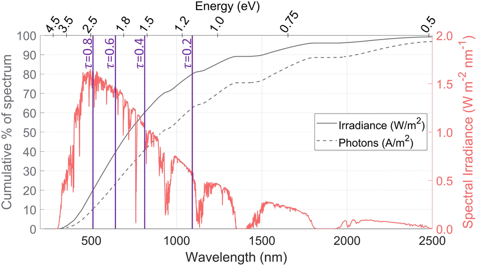 | ||
| Fig. 1 The AM1.5G solar spectrum (red) along with the cumulative percentage of both the irradiance and the number of photons (gray). Vertical purple lines indicate the low-energy optical cutoffs needed to transmit the indicated transmission fraction of irradiance (τ) to the solar receiver. | ||
System configurations using beam splitting for the co-production of heat and hydrogen require several elements: a parabolic concentrator, a cavity-type solar receiver, and the PEC itself. By changing which component is spectrally selective and modifying the order, many configurations can be envisioned, as shown in Fig. S1.† To consolidate the myriad of possible configurations into several representative cases, the configurations are classified into four types depending on if they use concentration on the PEC and/or on a solar receiver, as shown in Table 1, with possible system designs depicted in Fig. 2. These systems will be analyzed to compare the behavior based on the central design choices: concentrating vs. non-concentrating solar irradiation, vapor vs. liquid PEC reactant, and beam splitting with high and/or low optical cutoffs vs. no beam splitting. Fig. 2(a) shows a non-concentrating PEC capable of only low temperature PEC heat collection, similar to PV/T systems. In Fig. 2(b), the PEC has a transparent encapsulation, making the PEC itself the spectrally splitting element, where any photons not absorbed by the PEC are concentrated with the parabolic mirror onto the solar receiver. Fig. 2(c) is a concentrating system with a fully absorbing PEC, similar to solar dish systems producing hydrogen at the demonstration scale.19Fig. 2(d) uses a spectrally splitting mirror at the focus of the parabolic dish. In theory, each system can be run with liquid or vapor as the reactant, but not all configurations are valid for vapor (see Section 3).
| Type 1 | Type 2 | Type 3 | Type 4 | |
|---|---|---|---|---|
| Solar conc. on PEC | No | No | Yes | Yes |
| Solar conc. on receiver | No | Yes | No | Yes |
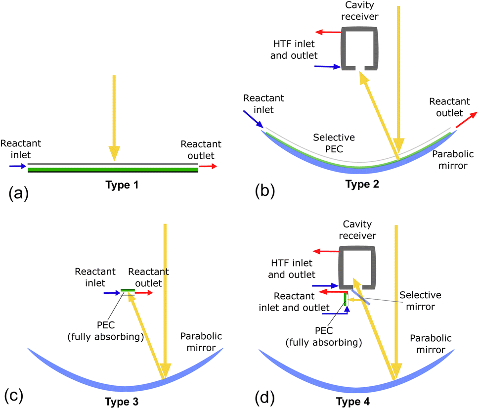 | ||
| Fig. 2 Systems of type 1–4 in parts (a) to (d), with green representing the PEC, blue being the mirrors, and yellow arrows representing solar radiation. Air is the heat transfer fluid (HTF) used in the solar receiver. | ||
Because vapor-fed PEC devices with solar concentration have been the subject of few modeling studies, this article first introduces the limits of solar concentration for these systems, based on criteria of both H2O mass flow and heat transfer. Second, a 0D, PEC-thermal integrated device model is detailed, which is applicable for both liquid and vapor phase reactants and includes a cavity-type solar receiver for concentrating systems. The model yields the hydrogen production and heat gain, with each system configuration compared based on energetic and exergetic efficiencies, for a range of band gaps. This shows which systems are most suited for the co-production of hydrogen and heat and at which band gaps the exergetic efficiency is maximized.
2 Limits for vapor-fed PEC devices with solar concentration
PECs using liquid water as the reactant can function at high solar concentrations, as the water stream both supplies ample reactant and cools the PEC effectively, as demonstrated experimentally.7,19 Switching to vapor as the reactant introduces more challenging conditions for the PEC device, as both the reactant density and heat transfer capacity are decreased.2.1 Limit imposed by reactant availability
Whether water is in vapor or liquid phase, supplying enough reactant for water splitting requires that more H2O molecules must enter the PEC device than are consumed in the reaction. This is typically not a limiting factor in liquid-fed electrolyzers, but in vapor-fed devices, the concentration of water vapor in the air is low enough that this may limit the reaction.3,4 Furthermore, a PEC device with solar concentration requires even more vapor to be converted to hydrogen per PEC surface area. The following fundamental analysis is meant to serve as a baseline for future device design by clearly showing which devices are not physically realizable and which are possible if a device is well-designed.
The device geometry in this analysis is a rectangular PEC with a glass cover placed several centimeters above the surface, as shown in Fig. 3(a). Air flows upward through the gap between the PEC surface and the glass, conveyed with a fan or possibly via buoyant convection. The mass flow rate of water vapor entering the device is calculated with eqn (1), which is the mass flow rate of air multiplied by the mass fraction of vapor in the air, H. H can be calculated with  , where ω is the humidity ratio, defined as the mass of vapor per mass of dry air, which can be found in psychrometric tables. The distance between the PEC surface and the glass is tgap, the width of the PEC is WPEC, the density of humid air is ρair, and the air velocity is Vair. Water molecules are consumed on the PEC surface at the rate given by eqn (2),20 where ηSTH is the solar-to-hydrogen efficiency, MH2O is the molar mass of water, and G is the Gibbs free energy of the reaction (237 kJ mol−1). The incident radiative flux is
  and C is the radiation concentration factor.
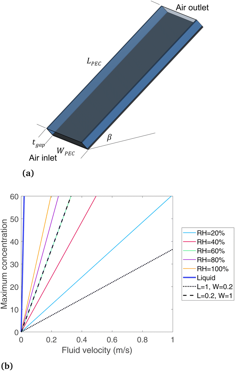 | ||
| Fig. 3 (a) Glass-covered PEC device design, and (b) maximum solar concentration, based on mass transfer of vapor, comparing relative humidities (colors), and device dimensions (dashed black), along with liquid water (thick blue line). If not stated otherwise, LPEC = WPEC = 0.2 m and RH = 60%. | ||
By enforcing ṁH2O,avail > ṁH2O,cons, eqn (1) and (2) are combined to form eqn (3), showing a linear relationship between the concentration possible and the air velocity needed to supply adequate vapor. Also visible in this equation is that a longer PEC device designs reduce the concentration possible, while increasing the gap thickness introduces more vapor, enabling a higher concentration.
| ṁH2O,avail = ρairVairtgapWPECH | (1) |
 | (2) |
 | (3) |
Eqn (1) and (2) are solved for various concentrations and air velocities, with results shown in Fig. 3(b). Parameters assumed are tgap = 2 cm, ηSTH = 0.10, and  = 1000 W m−2, T = 25 °C. The colored lines compare different relative humidity (RH) conditions while the PEC dimensions are held constant at LPEC = 0.2 m and WPEC = 0.2 m. For a specified air velocity, higher relative humidities enable higher concentrations. Even for a RH = 20%, typical in a desert region, enough water vapor is available for a solar concentration of 60, with an air velocity of 1 m s−1. Results are given for liquid water for comparison, which has a much higher maximum concentration than any vapor-phase device, with a velocity of only 0.019 m s−1 needed to sustain a concentration of 60.
Comparing the two black lines (dotted and dashed) shows how the maximum concentration depends on the device length and width. The dotted line is for a PEC that is long in the flow direction (1 m) and short in the width direction (0.2 m), while the dashed line is the opposite, with RH = 60% in both cases. The width has essentially no such impact, as the black dotted line (L = 0.2 m, W = 1 m, RH = 60%) falls directly on the green line (L = 0.2 m, W = 0.2 m, RH = 60%). In contrast, the device long in the flow direction (L = 1 m, dotted line) can only support much lower concentrations. The quantity of water vapor in the air is reduced as the air flows from inlet to exit, so a longer PEC devices need to have more vapor at the inlet to avoid being completely depleted at the outlet. Therefore, the length of a vapor-fed PEC in the flow direction is a critical design parameter to ensure ample vapor supply, and a PEC that is shorter in the flow direction appears more advantageous. This conclusion may be apparent even without a model, but it is useful to understand how the main design parameters affect and limit a vapor-fed PEC when envisioning scaled-up devices, since currently devices have only been built at the bench-top scale, where such factors are not considered. A non-ideal PEC device would require a substantially higher air velocity, since less than 100% of the vapor can be converted to hydrogen. Still, eqn (3) helps place the boundaries around the design of a vapor-based PEC device, ruling out any proposed design where this equation is not obeyed. It shows that enough water exists even in low humidity regions if the PEC can be designed to effectively draw vapor from the air.
2.2 Limit imposed by heat transfer
A PEC under solar concentration must dissipate more heat per surface area than a non-concentrated device to stay below temperature limit for a given PEC material. A steady-state thermal energy balance is applied to find the PEC surface temperature under various solar concentration factors. A portion of the incident radiative energy is converted to hydrogen, with all other heat dissipated via convection and radiation. The heat balance is shown in the ESI (Fig. S2, eqn (S1)–(S7)†). The air gap tgap is considered to be 2 cm, the solar to hydrogen efficiency is 10%, and the length and width are 0.2 m.The PEC surface temperature is shown in Fig. 4 at various solar concentrations, for both a low (0.1 m s−1) and high (10 m s−1) air velocity. If beam splitting is employed, this reduces the heat required to dissipate, as shown with dashed lines. 24% filtering corresponds to all photons below 1.2 eV, as found from Fig. 1. From this analysis, we conclude that using high solar concentration (>10 suns) on the PEC will not be a viable path forward for vapor-based PEC devices. Low concentrations (<10 suns) may be viable, especially if designed to enhance thermal management, for example by adding fins or a heat sink, or if PEC materials are developed to withstand high temperatures. Since these require specific engineering efforts, systems with solar concentration on the PEC will be considered with liquid water only, not vapor, in the remainder of this work (note that this applies to solar concentration on the PEC, not the solar thermal receiver, as these can be different after spectrum splitting, such as in Fig. 2(b)).
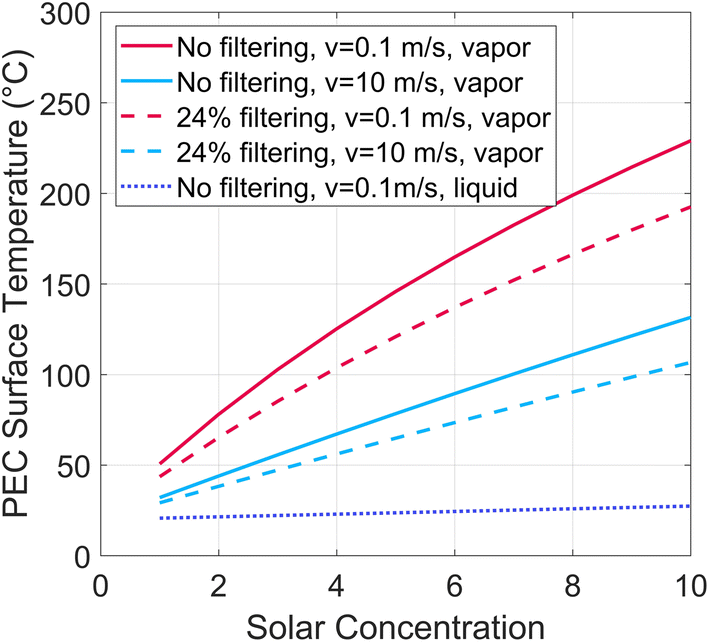 | ||
| Fig. 4 PEC surface temperature at various solar concentrations, showing low and high air flow rates, and with and without filtering of 24% of the incident irradiation (corresponding to all photons below a band gap of 1.2 eV). | ||
From Fig. 3 and 4 one design that does appear viable from a heat and mass transfer perspective is a vapor-fed PEC with low concentration (<5 suns). This could employ a non-tracking “compound parabolic concentrator” similar to designs used in solar water heating,21 a commercially available technology. We envision such a passive system may be one path to economical solar H2 production: the required PEC area is reduced by a factor of up to 5 due to solar concentration, non-tracking solar concentrators are an inexpensive technology without moving parts, and the vapor-fed PEC requires no high purity water supply. Air flow may also be induced via buoyant convection, further reducing cost and complexity. Such a system may be an economical means to produce hydrogen as a distributed energy resource. However, we now turn towards more complex systems also producing high temperature heat, which may be useful for industrial processes.
3 Combined PEC and thermal model
In this section, a device-level model is developed to examine and compare various PEC system designs, including those with liquid or vapor, and with or without solar concentration. So-called “0D” PEC models have successfully modeled liquid-fed PEC devices,2 where the photoabsorber and the electrochemical portions of the device are each modeled with a current–voltage (I–V) curve, referred to as the PV and EC curves, respectively. The intersection of the two curves gives the actual PEC operating current. The corresponding mass flux of hydrogen is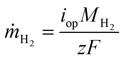 , where iop is the current density at the operating point, MH2 is the molar mass of hydrogen, F is Faraday's constant, and z is the number of electrons to transfer (2). Coupling this photoabsorber-electrochemical model to the thermal model is necessary as the PEC temperature both depends upon and affects the hydrogen production rate.
3.1 Solar radiation model
The hourly radiation profile shown in Fig. S4† is used as a representative moderately sunny day from the TMY data set22 (April 16, Paris, France). Solar radiation includes both beam (direct) and diffuse radiation, but only the beam component can be utilized after concentrating solar radiation. All systems are modeled with two-axis tracking, so the full direct normal irradiation (DNI) is incident to the concentrator (or to a flat device surface, in type 1) each hour. The diffuse radiation incident to the dish/surface changes each hour based upon the radiation conditions, and in addition, it varies slightly based upon the tilt angle due to the view factor from the dish/surface to the sky vs. ground (see eqn (S11)†). The total irradiation available is the sum of beam and diffuse components: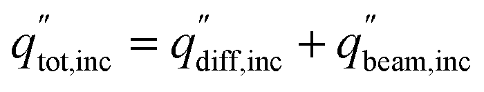 . Two-axis tracking is required to focus parabolic dish systems, whereas fixed-tilt or single-axis tracking are compatible with non-concentrating and linear concentrating (parabolic trough or linear Fresnel) systems. The full set of tracking equations are given in Section S4.†
3.2 Electrochemical model
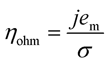
Experiments show that standard PEM electrolyzers designed for liquid water can be operated using the water vapor in air instead of liquid, though often at lower current densities.3,4,23Unlike with liquid water, the availability of water vapor imposes a limit on the current, manifested as a plateau of the EC curve, shown in Fig. 5 with data reproduced from Kumari et al.4 The vapor lines (colors) diverge from the liquid line (black), and the level of the plateau increases essentially linearly with flow rate in standard cubic centimeters per minute (SCCM). In the present model, vapor curves are modeled by first using the overpotentials for the liquid electrolyzer given by the first three terms on the right side of eqn (4), including the standard equilibrium potential (V0), the activation overpotential found with the Tafel correlation for the anodic and cathodic reactions (eqn (5)), and the ohmic overpotential (eqn (6)).1 Then, a new overpotential term is introduced, ηvap, in eqn (7) to enforce the plateau in current imposed by the mass transport limitations of vapor. Constants c1, c2, and c3 are found with curve-fitting to match this vapor-fed electrolyzer (c1 = −0.6105, c2 = 0.09659, and c3 = 0.0009717), and once found, the modeled curves closely follow the experimental curves over a range of relative humidity and flow rate conditions, as indicated by the dashed curves in Fig. 5. The value of the plateau or limiting current (ilim) depends on the conditions of the vapor stream and the device architecture, and is estimated from experimental data by interpolating data from Kumari et al.4 for both the flow rate and the relative humidity. The flow rate is adjusted to keep the outlet temperature at a constant 65 °C, and the RH is specified at 50% for the remainder of work (see Section S3† for details).
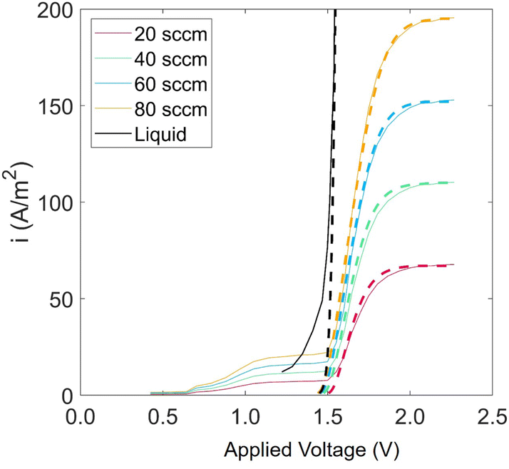 | ||
| Fig. 5 Current density versus applied potential curves for an EC component operated with vapor for RH = 40% and various flow rates. Solid curves are experimental data, linearly scaled to match flow rate and RH conditions, starting with the base-case experimental curve of RH = 80% and flow rate = 20 SCCM4 (eqn (S8)†). Modeled curves (dashed lines) are from eqn (4). | ||
We take these electrochemical curves as representative of the physics in a general PEC cell, though the exact construction and materials used may affect the curve. In the vapor-fed PEC device investigated by Zafeiropoulos et al.,24 ionomers are used to enhance the absorption of water vapor from humidified air, increasing the H2O available at the reaction site. A solid proton-conducing electrolyte was use in this case to connect the two electrodes, and in related work a transparent and conductive support has been developed.25 These advancements, plus the specific electrolyte used, band bending, and electric double layer effects may also all play a role in the effectiveness of a final PEC device, but these details are neglected to focus on thermal/PEC hybridization for a generic PEC device.
| V = V0 + ηact + ηohm + ηvap | (4) |
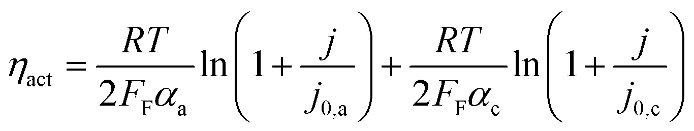 | (5) |
 | (6) |
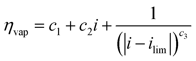 | (7) |
3.3 Photoabsorber model
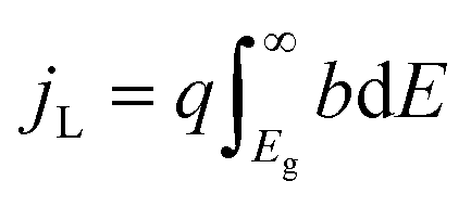
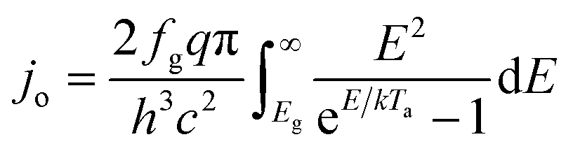
An ideal dual-junction photoabsorber is modeled in this study using the Shockley–Queisser “detailed balance” equations. Eqn (8)–(10),13,26 solve for the current density (j), the light induced current (jL), and the reverse saturation current (jo). T is the temperature, b is the photon flux normal to the surface per energy dE. Constants q, h, c and k are the elementary charge, the Planck's constant, the speed of light, and the Boltzmann constant. Each photoabsorber is modeled with these equations, where all photons having an energy greater than the top junction band gap (E > Eg,1) are absorbed by the top junction, leaving only the photons with Eg,2 < E < Eg,1 available for the lower junction (Eg,2 and Eg,1 are the lower and upper band gaps, respectively). The geometric factor fg is 2 for the top junction and 1 for the bottom junction, corresponding to the number of sides from which emission is possible. The spectrum (b) is AM1.5G scaled in magnitude to the total radiative intensity from the TMY data set at the modeled hour. The junctions are connected in series such that the cell voltage is the sum of the two voltages and the cell current is the minimum of the two photocurrents generated.
| j = jL − jo(e(kV/kTa) − 1) | (8) |
 | (9) |
 | (10) |
3.4 Thermal model
The PEC surface temperature is found using a heat balance previously described in Section 2.2 (Fig. S2, eqn (S1)–(S7)†). The reactant, either liquid water or moist air, cools the PEC to keep it from overheating, with the heat gained by the reactant stream considered to be a useful product. The outlet temperature of the reactant stream is set to 65 °C, and the mass flow rate is adjusted to satisfy this temperature constraint. This outlet temperature is chosen low enough to keep the PEC from overheating, while high enough to deliver a useful temperature for some industrial or residential heating needs.15 The inlet air temperature is 20 °C.For systems employing solar concentration, heat is also collected in a cavity type solar receiver, with air as the heat transfer fluid. Compared to liquid heat transfer fluids (e.g. molten salts), air has the advantages of being non-toxic, ubiquitous, and capable of reaching high temperatures. The solar receiver modeled is similar to Poživil27 and Hischier,28 who presented a detailed computational fluid dynamics model of the receiver. A similar receiver design is modeled in the present work, but the analysis is carried out using a simplified quasi-2D model, as the goal is to predict trends in heat gain for a wide array of operating conditions. The radiative power entering the aperture (qrad) is calculated with eqn (11), and heat losses are modeled to find the heat gain of the receiver (see Section S9† for details). ηopt,rcv is the product of the optical losses due to each mirror (reflectivity of 0.94) and each glass sheet (transmissivity of 0.92). ηspill is the fraction of spilled radiation, assumed to be 0.85. The aperture of the solar receiver and the PEC are both 8 cm in diameter, and the dish diameter is 2.5 m, for a geometric concentration ratio of 977. Air enters the receiver at ambient temperature (20 °C), and the flow rate is varied to fix the outlet temperature to 500 °C. The transmission fraction (τ) is the fraction of irradiance directed to the receiver after any beam splitting. Referring to Fig. 1, τ is the integral of the spectral irradiance below Ecut,low and above Ecut,high, divided by the irradiance of the whole spectrum (1000 W m2 by definition for AM1.5G). Alternatively, τ can be found by reading the cumulative percentage of the irradiance in each region using the solid gray line.
 | (11) |
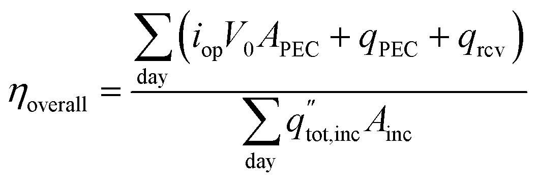
The system configurations in Fig. 2 have three useful products: thermal energy at 65 °C collected from the PEC surface, thermal energy from the cavity solar receiver at 500 °C, and hydrogen gas. Two metrics, the energetic and exergetic efficiency, are used to classify the overall output considering all three products.
The overall daily solar-to-products energetic efficiency is given in eqn (12), defined here as the daily sum of the energy converted into useful products divided by the daily incident radiation. The operating current each hour is iop, the area of incident sunlight is Ainc (either the dish area, or the PEC surface area in the case of Type1), and V0 is 1.23 V. The heat collected from the PEC and receiver are qPEC and qrcv. The daily total radiation available (including both beam and diffuse components) is  .
.
 | (12) |
In the field of beam-splitting PV/T systems, the value of the two products (electricity and heat) has been related under the assumption that thermal energy is 1/3 as valuable as electricity, as this roughly matches the conversion efficiency from heat to work in a thermal power plant.18 In that study, the value of these co-products is optimized by changing the low and high optical cutoff wavelengths, but no regard was given to the temperature of the heat. We would like to add perspective that the value of heat is highly dependent on the temperature: a near perfect thermal efficiency can be obtained by collecting heat just above the ambient temperature, but such heat has a low value. Therefore, we extend the analysis to include exergy in our investigation of PEC systems. Exergy is maximum theoretical amount of work obtainable by bringing a system into equilibrium with its environment,29 placing value on the temperature of the heat. The exergetic efficiency is useful in particular if the heat is destined for a power cycle (e.g. Rankine cycle). Since the present analysis is agnostic towards the final use of the heat (which could, for example, be a power cycle or thermal input to accelerate a chemical reaction), we use the exergy as a proxy for value of usefulness of the heat stream. For a particular use case (e.g. heating a greenhouse with 50 °C heat, or supplying heat to a reactor at 400 °C) an energy analysis may suffice, but for comparing between system configurations that produce hydrogen and heat at both low (65 °C) and high (500 °C) temperatures, exergy is used here to account for the different value of the products.
The daily overall exergetic efficiency from all three products is calculated with eqn (13), where ṁPEC and ṁrcv are the mass flow rates of the heat transfer fluids in the PEC (air or water) and solar receiver (air). ψ is the flow exergy at the inlet (i) and exit (e), where flow exergy ψ = h − T0s, with h being the enthalpy, s being entropy, and T0 being the dead state temperature (20 °C). NH2 is the molar flow rate of hydrogen produced, and bch is the chemical exergy of hydrogen gas and water in either vapor or liquid form, depending upon the reactant phase. Values are given in Table S1,† with a reference state of 20 °C and 101.325 kPa. The denominator is the exergy available via solar radiation, where Tsun is the sun temperature, 5800 K.30,31
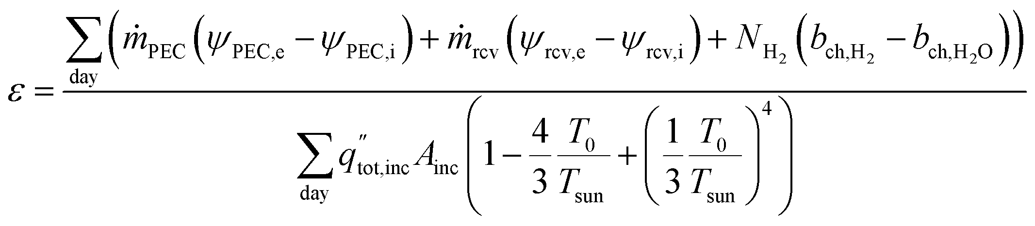 | (13) |
4 Results and discussion
Total daily hydrogen and heat production, and the corresponding energetic and exergetic efficiencies are found for the four system configurations shown in Fig. 2 to compare the trade-offs and optimal conditions. Both vapor and liquid are considered as the reactant, though Type3 and Type4 are not compatible with vapor, as the PEC is subject to high solar concentration, leading the PEC to overheat (see Section 2.2). Thus, the six designs are referred to as Type1-liq, Type1-vap, Type2-liq, Type2-vap, Type3-liq, and Type4-liq. Results are compared between six system configurations for a fixed set of band gaps in Section 4.1, and the band gaps are varied to find the optima in Section 4.2. In Section 4.3 effects of non-ideal photoabsorbers, sun-tracking scheme, and location are examined.4.1 Fixed band gaps
A base-case is considered where the band gaps are 1.2 and 1.788 eV, which is in a promising range noted by previous studies on PECs without solar concentration,32 and it is a current-matched combination according to the present model. For the Type4-liq beam splitting configuration, the lower optical cutoff for beam splitting is at 1.2 eV, and there is no high optical cutoff.The electrochemical and photoabsorption curves are shown for each hour of the day in Fig. 6 for Type2-vap and Type3-liq (chosen to show liquid and vapor phase reactants, and with/without solar concentration), and the rest are shown in Fig. S5.† In both cases, the current of the photoabsorption curve is highest near midday due to stronger radiation. As shown in Fig. 6(a), for a vapor-fed PEC the limiting current of the electrochemical curve moves up towards midday as well because the air flow rate must be increased to maintain a steady 65 °C outlet temperature while the incident radiation increases. A higher vapor flow causes ilim to increase as well (Section 3.2). The liquid electrochemical curve increases without a mass transfer limit. The PV curves shown in Fig. 6(b) have similar shape but much higher magnitude due to the solar concentration on the PEC, which has a geometric concentration of 977.
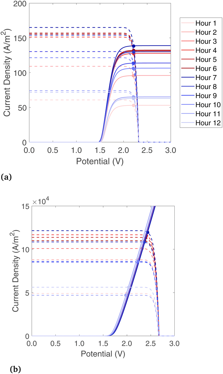 | ||
| Fig. 6 Photoabsorber and electrolyzer current density versus voltage behavior for each hour of the day, for (a) Type2-vapor and (b) Type3-liquid. PEC heat collection is fixed with an outlet temperature of 65 °C, and hour number 1 corresponds to 7 AM local time in Paris, France. | ||
Daily hydrogen production and the two forms of heat gain are shown in Fig. 7(a). Type1-vap, Type1-liq, and Type2-liq all have essentially the same hydrogen production, as the EC curves intersect in the plateau region of the PV curve in all cases. Compared to Type1-vap, Type2-vap has a slightly lower hydrogen production because the photons with E < 1.2 eV (24% of the radiative power) are allowed to pass through, so the PEC is heated less, and the air flow must be lower to maintain a 65 °C outlet temperature. This results in a slightly lower ilim and a PV-EC intersection lower than the plateau (see Fig. S5†). Type3-liq and Type4-liq both have a lower hydrogen output because the PEC cannot utilize diffuse radiation after solar concentration; this shows a source of inefficiency in any design that uses concentrated radiation on the PEC and is operated in a location or during a season with relatively low direct fraction of irradiation. In addition, concentrating before the PEC introduces an additional optical loss before the PEC compared to Type1 and Type2 systems, also reducing the H2 produced. Note that in our analysis all types use tracking (even Type1 and Type2 that operate without concentration), consequently the types that do not use concentration do not suffer from the typical cosine losses of fix installed panels (such fixed installed panels would typically be limited to GHI). Comparing thermal energy in Type1 and Type2 systems, thermal energy collected from the PEC at 65 °C is higher with a liquid reactant compared to vapor due to the superior heat transfer properties of liquid water. The beam splitting used by Type2 means less heat is collected compared to Type1, as some radiation is reflected to the solar receiver for collection at 500 °C, which is collected at a lower thermal efficiency than low-temperature heat gain from the PEC. Type3 shows the highest heat gain overall, though it is all low-temperature heat. The heat gain is higher than even Type1-liq, as the radiation is concentrated, so the PEC area is small which helps to minimize thermal losses. Considering all six configurations, the overall trends are that the highest H2 production is with systems having no concentration on the PEC, due to the wasted diffuse component and optical losses, and the highest thermal efficiencies are found with a liquid reactant and with no beam splitting.
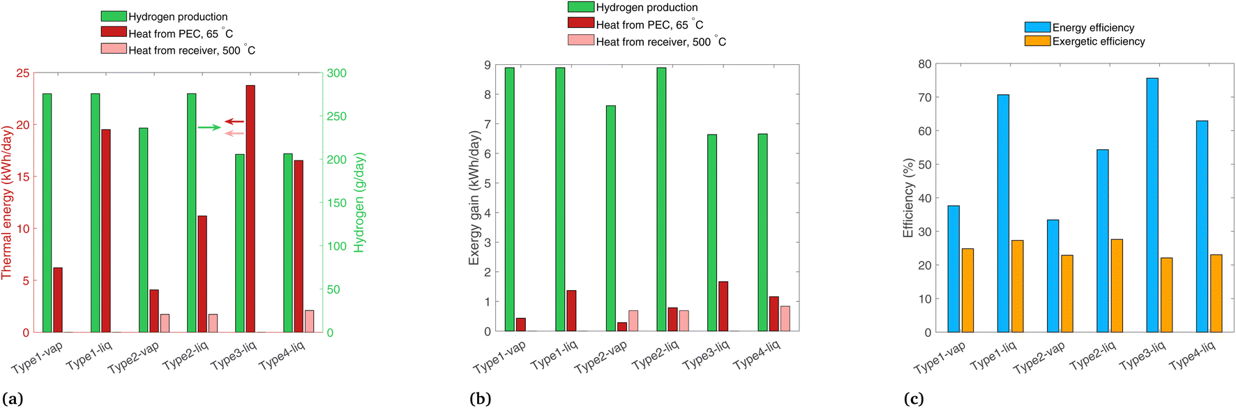 | ||
| Fig. 7 Results for each system modeled for band gaps of 1.2 and 1.788 eV, for (a) daily thermal energy gain, (b) daily exergy gain, and (c) overall energetic and exergetic efficiencies. | ||
The exergy gain from each product is shown in Fig. 7(b). In all configurations, hydrogen carries the most exergy of all the products due to its extremely dense chemical energy content. Note that an ideal photoabsorber is assumed in this analysis, whereas current technology would yield considerably lower exergy values (Section 4.3). The picture considering exergy is quite different to thermal energy (Fig. 7(a)), as the high thermal energy gains from the PEC at 65 °C actually carry very little exergy.
Energetic and exergetic efficiencies are shown in Fig. 7(c). Energetic efficiencies are especially high for Type1-liq and Type3-liq, as both feature heat absorption by the PEC without any beam-splitting. The liquid heat transfer fluid yields higher thermal efficiencies than vapor-based systems. The lowest exergetic efficiency is Type3-liq, as hydrogen output is lower than most others, even though it captures a high amount of low-temperature heat. The highest exergetic efficiencies are found in Type1-liq, and Type2-liq, but for different reasons. Type1-liq captures a high amount of low-temperature heat, whereas Type2 has much less heat gain from the PEC but it compensates with the high-exergy heat in the solar receiver. Thus, we identify Type1-liq and Type2-liq as two possibilities for delivering a high output in terms of exergy and thermodynamic value, but between these, only Type2 can produce high temperature heat for industrial processes.
4.2 Varying band gaps and optical cutoffs
Now that the systems have been compared for a static set of band gaps, we vary the band gaps to see how the products of each system are affected. The daily results are shown in Fig. 8 for Type1, Type2, and Type3 systems (Type4 is analyzed subsequently). The upper band gap is current-matched to the lower band gaps shown on the charts, with Eg,1 values shown on the top x-axis. Each system shows a peak in hydrogen production between 0.8 and 1.2 eV. Lowering the band gaps raises the plateau in the PV curve (higher isc), while decreasing the VOC. Thus, starting at the band gaps corresponding to the peak H2 production, lowering the band gaps causes the intersection of the iV curves to fall in the downward slope of the PV curve instead of the plateau. On the other hand, increasing the band gap from the peak value simply decreases the height of the PV curve plateau, again resulting in a lower operating current. The two vapor-fed systems peak at a lower hydrogen production than their liquid-fed counterparts, as is generally expected based on the mass transport limitations of vapor. However, their peak H2 output occurs at a higher band gap than their liquid-fed counterparts, as higher band gaps (specifically higher VOC) are needed to optimize the current given the vapor-induced plateau in the EC curve. The PV and EC curves at their respective peaks are shown in Fig. S6.† This difference may become important in developing vapor fed PEC systems, as simply replacing the liquid reactant with vapor without also changing the materials (e.g. the photoabsorber with its specific band gaps) would lead to poor performance. For example, as shown in Fig. 8(a) and (c), increasing the band gaps from where liquid peaks (Eg,2 = 0.8 eV) to the vapor peak (Eg,2 = 1.0 to 1.1) results in roughly a doubling of the H2 output. | ||
| Fig. 8 Daily hydrogen production, energy efficiency, and exergetic efficiency for system types (a) Type1-vap, (b) Type1-liq, (c) Type2-vap, (d) Type2-liq, (e) Type3-liq. Low energy band gap shown on the lower x-axis, high energy band gap shown on the upper x-axis. | ||
The peak exergetic efficiency corresponds to the peak H2 in nearly all cases, as the exergy contribution from H2 dominates the among the three outputs. Though the trends in energy efficiency are quite varied, the highest is for the Type3-liq system (76%) due to the combination of a liquid heat transfer fluid, a small aperture area to limit thermal losses, and all low-temperature heat collection. However, the Type3-liq system has a peak exergetic efficiency of only 22.5%, much lower than the Type1-liq or Type2-liq systems (35.0% and 34.6%), and lower than even the vapor-fed systems (25.3% and 23.1%). These trends should emphasize again that the energetic efficiency can be a misleading metric for evaluating all three product streams simultaneously.
Finally, we focus on the beam splitting configuration, Type4-liq, which allows for maximum optical flexibility: the band gaps can be modified, and the low and high optical cutoffs can be varied to achieve different τ values using a spectrum splitting mirror. All photons with energy below the lower optical cutoff (Ecut,low) and above the upper optical cutoff (Ecut,high) are directed to the solar receiver, whereas photons with energy in between are reflected to the PEC. τ is the fraction of the cumulative irradiation curve (Fig. 1) falling outside of these two cutoffs. An ideal selective mirror is assumed, having a perfect step function at the cutoffs and therefore no heat absorption, though in reality this would likely require active cooling. Given the multitude of options in terms of cutoff and band gap values, the following analysis is carried out to show the optimal combinations and trade-offs in terms of the three products. First, the optical cutoffs are varied keeping the band gaps constant. Second, the band gaps and cutoffs are varied together.
Results are shown in Fig. 9, where the band gaps are held constant (Eg,2 = 1.2, Eg,1 = 1.788) and the low and high energy cutoffs are each varied. Daily hydrogen production is shown in Fig. 9(a), where the highest production is at a small Ecut,low and high Ecut,high, corresponding to essentially no photons diverted from the PEC. Decreasing Ecut,low generally increases the H2 output, but proceeding below the Eg,2 results in no additional H2 output, since these photons do not have enough energy for H2 production. The vertical nature of the contours at Ecut,low > 1.5 is because the two photoabsorbers operate in series, taking the minimum of the two photocurrents. With Ecut,low > 1.5 eV the lower energy photoabsorber governs, so increasing Ecut,high delivers more radiation to the PEC but results in no more photocurrent overall.
 | ||
| Fig. 9 Results for the beam-splitting Type4-liq system, combined effect of varying both low and high energy optical cutoffs, with band gaps fixed at 1.2 and 1.788 eV, showing (a) daily total hydrogen production, (b) energetic efficiency, and (c) exergy efficiency. | ||
The energetic efficiency, including contributions from all three products, is shown in Fig. 9(b). Unlike H2 production, proceeding with a low cutoff below the lower band gap does increase the energy efficiency, as lowering Ecut,low increases the radiation on the PEC, and though no more H2 is produced, this increases the heat transfer from the PEC at 65 °C. The vertical nature of the H2 lines at Ecut,low > 1.5 is not seen here, as increasing Ecut,high means more energy is delivered to the PEC and less to the solar receiver, leading to more heat collection as the PEC collects energy at a higher efficiency than the cavity solar receiver.
In Fig. 9(c), the highest exergetic efficiencies are where Ecut,low = Eg,2. Increasing Ecut,low above Eg,2 deprives the PEC of photons and results in less H2. Decreasing the Ecut,low to below the lower band gap also decreases the overall exergy, as this results in more (low exergy) PEC heat gain, less (high exergy) heat gain from the solar receiver, and an identical H2 output.
Because the preceding analysis (regarding Fig. 9) shows the highest exergy when Ecut,low is equal to Eg,2, these properties are now varied in unison between 0.6 and 1.7 eV (keeping them equal), while the optical cutoffs are varied (see in Fig. 10). Eg,1 is chosen in each case such that it is current-matched to Eg,2. In Fig. 10, the highest H2 output is at Ecut,low (and Eg,2) of 1.1 eV, with a high cutoff above 3.2 eV. Similar to the previous case, energy efficiency increases at low Ecut,low and high Ecut,high as this maximizes the heat gain from the PEC. The exergetic efficiency largely follows H2, with a maximum value of 23.6% found at Eg,2 and Ecut,low = 1.1 eV, with a corresponding Eg,1 of 1.71, and Ecut,high > 3.2 eV. Increasing Ecut,high beyond 3.2 eV makes little difference to the exergy, as very few photons are available in this region. In fact, an extremely high Ecut,high is the same as not using any cutoff at all. This matches the general expectation that depriving the PEC of high energy photons will severely hurt H2 production, but it is in direct contrast to the PV/T studies with a Si photoabsorber16 where a high cutoff is used to optimize the system on a thermal energy basis.
 | ||
| Fig. 10 Results for the Type4-liq system, showing (a) daily total hydrogen production, (b) energetic efficiency, and (c) exergy efficiency. The lower band gap and low cutoff are varied together, and upper band gap is set to be current-matched to the low band gap value. High cutoff is varied independently. | ||
An extensive analysis has been conducted to find the optimum band gaps and (where applicable) the optical cutoffs for each system type. The conditions at the maximum exergy point are summarized in Table 2. The Type1-liq and Type2-liq systems stand out with the highest exergetic efficiencies, driven primarily by low optical losses, a liquid reactant, and the use of diffuse radiation by the PEC. The Type1-vap and Type2-vap systems show an optimum at higher band gaps than liquid systems, but the exergetic efficiency is still lower than liquid systems due to vapor transport which limits H2 production. The Type4-liq system was optimized for both the band gaps and optical cutoffs, but even after this optimization the exergetic efficiency is comparatively low. It can, however, provide high temperature heat, which cannot be supplied by Type1 or Type3 systems, and may prove industrially useful.
| Config. | Exergetic efficiency | E g,2 (eV) | E g,1 (eV) | Optical cutoffs (eV) |
|---|---|---|---|---|
| Type1-liq | 35.0 | 0.8 | 1.55 | — |
| Type1-vap | 25.3 | 1.1 | 1.71 | — |
| Type2-liq | 34.6 | 0.8 | 1.55 | E cut,low = 1.55 |
| Type2-vap | 23.1 | 1.0 | 1.71 | E cut,low = 1.71 |
| Type3-liq | 22.5 | 1.1 | 1.71 | — |
| Type4-liq | 23.6 | 1.1 | 1.71 | E cut,low = 1.1, Ecut,high > 3.2 |
4.3 Effects of non-ideal photoabsorbers, location, and tracking
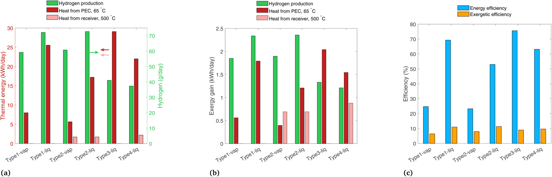
In this section, we change several of the main assumptions of the previous analyses, with results shown for non-ideal photoabsorbers, a comparison of 2D tracking vs. a fixed-tilt panel, and the effect of a location with a high fraction beam radiation. In each case, only one of these parameters is varied at a time, so the variation is clear between these results and those of the previous analyses.Fig. 11 shows the results for a non-ideal photoabsorber with roughly a 6% solar-to-hydrogen efficiency. The photoabsorption curve is modeled as a diode with a series and shunt resistance (see Section S7† for details), and the electrochemical curve is not changed from the previous analysis. The tracking and solar radiation profile/location are still those of the base case (2-axis, and Paris, France). Fig. 11(a) shows similar trends as in the ideal case (Fig. 7(a)), though the PEC heat gain is slightly higher in each system due to the extra heat which was previously converted to H2. In Fig. 11(b), the H2 contribution to exergy is shown to be much lower because of the reduced H2 production compared to the ideal case, making it in the same range as the other two sources of exergy, and in some cases (Type3-liq, Type4-liq) it is no longer the highest exergy stream. Shown in Fig. 11(c), Type1-liq and Type2-liq still have the highest exergetic efficiencies with non-ideal photoabsorbers, as was the case for ideal photoabsorbers.
 | ||
| Fig. 11 Results with non-ideal photoabsorbers, with band gaps of 1.2 and 1.788 eV, showing (a) daily thermal energy gain, (b) daily exergy gain, and (c) overall energetic and exergetic efficiencies. | ||
A comparison is shown in Fig. 12(a) for the Type1 systems between 2-axis tracking and a fixed-tilt system with a tilt angle equal to the latitude for Paris, France (48.9°). The other parameters are those of the base case (ideal photoabsorbers, and radiation profile of Paris). The liquid and vapor systems lose 24% and 26% of their original exergy gain by omitting the tracker. This shows that typically non-tracking, non-concentrating approaches have comparable optical losses to tracking, concentrating systems (the former limited to GHI, the latter limited to DHI).
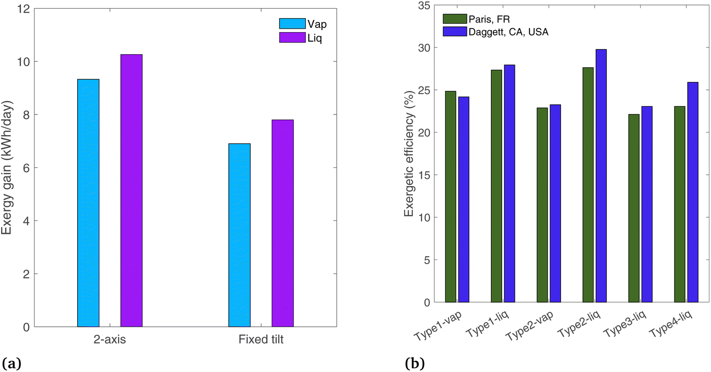 | ||
| Fig. 12 (a) Comparison of Type1 systems with ideal photoabsorbers using 2-axis tracking vs. a fixed tilt system, for Paris, FR, and (b) effect of location and radiation profile, showing Paris, FR vs. Daggett, CA, USA. | ||
Finally, the location is changed to Daggett, CA, USA, to see the effects of a desert region where the beam radiation fraction is higher than in Paris. A clear day is chosen with DNI peaking at 1009 W m−2 (March 17,22 solar radiation profile shown in Fig. S4(b)†). Of the total radiation incident to the PEC surface, 20.3% is diffuse in Paris, whereas in Dagget, the diffuse fraction is 7.1% (on the analyzed days). The exergetic efficiency is plotted in Fig. 12(b). The concentrating systems (Type2, 3, and 4) all show increased efficiencies in Daggett where the beam radiation fraction is higher, as only beam radiation can be concentrated. This confirms the assumption from the concentrating solar power field that concentrating systems are more suited to arid locations where solar radiation has a higher beam radiation fraction. This is not a critical distinction for non-concentrating systems (Type1), as both diffuse and beam radiation are used by the PEC. The difference in exergetic efficiency between the two locations is up to 12.3% for the Type4-liq case. Note that this comparison is made on an exergetic efficiency basis, and overall exergy gain in Daggett is also expected to be higher simply due to the higher levels of incident radiation.
5 Conclusions
We modeled numerous PEC device designs that elegantly integrate hydrogen generation and low/high-temperature heat co-generation to find which combinations of reactant phase (liquid or vapor), solar concentration, and optics are promising for development. Initially, vapor-fed PEC systems are analyzed on both a H2O mass transfer basis and a heat transfer basis. At low solar concentrations (e.g. 10) there is enough vapor even in arid climates to satisfy the H2O requirement if the device is very well designed. Heat transfer poses a more stringent requirement, with only a few (2–8) suns possible before overheating, depending on how well the device is engineered to dissipate heat and the temperature limits of the PEC materials used.Four different PEC system designs are compared, ranging from a simple PEC with tracking but no solar concentration (Type1) to a design with solar concentration on the PEC, beam splitting, and heat collection in a solar receiver (Type4). These represent the extremes in complexity. With three different co-products possible (hydrogen, low-temperature heat, and high-temperature heat), comparing systems on strictly an energy basis leads to the conclusion that Type3-liq is the highest performing system, as it outputs a high amount of low-grade heat. With low-temperature heat known to have relatively little thermodynamic or economic value, exergy is introduced to better align the value of products to their potential for doing useful work.
Ideal photoabsorbers are first modeled to show the upper limits in hydrogen output. The chemical exergy of hydrogen is quite high compared to the thermal outputs, making H2 by far the largest driver of exergy when modeling ideal photoabsorbers, indicating Type1-liq and Type2-liq produce the most exergy overall. Comparing the outputs across the system types, those using solar concentration on the PEC have a reduced hydrogen output due to extra optical losses and diffuse radiation which cannot be concentrated.
The band gaps chosen for the photoabsorber in each system were varied to find the effect on the efficiency and distribution of the three products. In systems not concentrating radiation on the PEC (but still tracking the sun), the band gap corresponding to the peak exergy is found to be higher for a vapor-fed PEC compared to a liquid-fed PEC (Eg,2 of 1.1 vs. 0.8 eV, respectively) due to the reduced reactant availability in vapor. Thus, simply switching the PEC from a liquid reactant to vapor will lead to reduced performance compared to redesigning the PEC with higher band gap materials. Finally, the effect of changing the optical cutoffs is compared for the beam splitting system (Type4), with the highest exergy found when the lower cutoff and the lower band gap are both 1.1 eV, the high band gap is 1.71 eV, and the high optical cutoff is above 3.2 eV.
The Type2 system has not been built to date, but it is modeled prospectively to see if it would be a useful and viable concept. It has the positive aspects of utilizing diffuse radiation and having low optical losses before the PEC, while it still can produce heat at high temperatures. Thus, the Type2 system does indeed appear advantageous, run either as a liquid-fed system with high output or as a vapor-fed system which may reduce complexity and costs. The drawback is that it may not be feasible with currently available materials and technology, as the PEC support and encapsulation would have to be nearly fully transparent to transmit light to the solar receiver. Though not currently available as an off-the-shelf part, some substrates for PECs that are transparent, conductive, and porous are currently under development.25
Last, some assumptions from the previous analysis are relaxed to see their effects. The analysis with non-ideal photoabsorbers shows that similar to the ideal photoabsorbers, Type1-liq and Type2-liq are the best performers on an exergy basis. Eliminating the 2-axis tracker to use a simpler fixed-tilt PEC in non-concentrating application (Type1) would reduce exergy gain substantially, by 24% for liquid or 26% for vapor. No tracking is typical for non-concentrating approaches. In this case, non-concentrating types are equally competitive as concentrating types. Finally, the location is varied from Paris, France with a high diffuse fraction to Daggett, USA with high beam fraction. Most modeled systems perform better in Daggett than Paris, especially those using solar concentration, resulting in an increase in exergetic efficiency of up to 12%.
Throughout this study, the vapor-fed systems are always less efficient than the same system run with liquid water, as both heat transfer and electrochemistry are more efficient with a liquid phase reactant. Vapor-fed devices have been the subject of little research to this point, and while their efficiencies may increase, they are likely to always be less efficient than liquid systems given the low concentration of vapor in the reactant stream. However, the benefit of vapor-fed systems is eliminating the supply and purification of water, which would lower costs and may enable more remote or decentralized designs. We have explored various designs and analyzed them on an energy and exergy basis, but techno-economic modeling is needed to quantify the monetary benefits of vapor-based hydrogen production. Such studies are currently underway.33
Data availability
Data for this article, including numerical modeling results are available on the Zenodo repository: https://doi.org/10.5281/zenodo.12750989.Author contributions
EJ: conceptualization, methodology, software, writing – original draft. SH: conceptualization, project administration, writing – review & editing.Conflicts of interest
There are no conflicts to declare.Acknowledgements
This project has received funding from the European Union’s Horizon 2020 research and innovation programme under grant agreement No. 883264 (Sun-to-X project).References
- M. Dumortier, S. Tembhurne and S. Haussener, Energy Environ. Sci., 2015, 8, 3614–3628 RSC.
- S. Haussener, Y. Gaudy and S. Tembhurne, Energy and Environment Series, Royal Society of Chemistry, Cambridge, 2018, pp. 239–265 Search PubMed.
- J. M. Spurgeon and N. S. Lewis, Energy Environ. Sci., 2011, 4, 2993 RSC.
- S. Kumari, R. Turner White, B. Kumar and J. M. Spurgeon, Energy Environ. Sci., 2016, 9, 1725–1733 RSC.
- J. Rongé, S. Deng, S. Pulinthanathu Sree, T. Bosserez, S. W. Verbruggen, N. Kumar Singh, J. Dendooven, M. B. J. Roeffaers, F. Taulelle, M. De Volder, C. Detavernier and J. A. Martens, RSC Adv., 2014, 4, 29286–29290 RSC.
- M. A. Modestino, C. A. Diaz-Botia, S. Haussener, R. Gomez-Sjoberg, J. W. Ager and R. A. Segalman, Phys. Chem. Chem. Phys., 2013, 15, 7050 RSC.
- S. Tembhurne, F. Nandjou and S. Haussener, Nat. Energy, 2019, 4, 399–407 CrossRef CAS.
- M. Dumortier and S. Haussener, Energy Environ. Sci., 2015, 8, 3069–3082 RSC.
- B. Wang, M. Ni and K. Jiao, Sci. Bull., 2022, 67, 1530–1534 Search PubMed.
- S. Tembhurne and S. Haussener, J. Electrochem. Soc., 2016, 163, H988–H998 CrossRef CAS.
- J. Rongé, T. Bosserez, L. Huguenin, M. Dumortier, S. Haussener and J. A. Martens, Oil Gas Sci. Technol., 2015, 70, 863–876 CrossRef.
- J. M. Miller, Sci. Pap. Bur. Stand., 1919, 15, 367 Search PubMed.
- K. T. Fountaine, H. J. Lewerenz and H. A. Atwater, Nat. Commun., 2016, 7, 13706 Search PubMed.
- T. Chow, Appl. Energy, 2010, 87, 365–379 Search PubMed.
- C. Lamnatou, R. Vaillon, S. Parola and D. Chemisana, Renewable Sustainable Energy Rev., 2021, 137, 110625 Search PubMed.
- F. Crisostomo, R. A. Taylor, A. Mojiri, E. R. Hawkes, D. Surjadi and G. Rosengarten, Proceedings of the ASME 2013 Heat Transfer Summer Conference, Minneapolis, Minnesota, USA, 2013, p. V001T01A029 Search PubMed.
- B. C. Riggs, R. Biedenharn, C. Dougher, Y. V. Ji, Q. Xu, V. Romanin, D. S. Codd, J. M. Zahler and M. D. Escarra, Appl. Energy, 2017, 208, 1370–1378 CrossRef.
- F. Crisostomo, R. A. Taylor, T. Zhang, I. Perez-Wurfl, G. Rosengarten, V. Everett and E. R. Hawkes, Renewable Energy, 2014, 72, 79–87 Search PubMed.
- I. Holmes-Gentle, S. Tembhurne, C. Suter and S. Haussener, Nat. Energy, 2023, 1–11 Search PubMed.
- I. Holmes-Gentle, F. Alhersh, F. Bedoya-Lora and K. Hellgardt, Photoelectrochemical Solar Cells, Wiley, 1st edn, 2018, pp. 1–41 Search PubMed.
- R. Winston, Sol. Energy, 1974, 16, 89–95 Search PubMed.
- T. Huld and I. Pinedo Pascua, Typical Meteorological Year, European Commission, 2017 Search PubMed.
- C. Xiang, Y. Chen and N. S. Lewis, Energy Environ. Sci., 2013, 6, 3713 RSC.
- G. Zafeiropoulos, H. Johnson, S. Kinge, M. C. M. Van De Sanden and M. N. Tsampas, ACS Appl. Mater. Interfaces, 2019, 11, 41267–41280 CrossRef CAS PubMed.
- M. Caretti, E. Mensi, R.-A. Kessler, L. Lazouni, B. Goldman, L. Carbone, S. Nussbaum, R. A. Wells, H. Johnson, E. Rideau, J.-h. Yum and K. Sivula, Adv. Mater., 2023, 35, 2208740 Search PubMed.
- I. Holmes-Gentle and K. Hellgardt, Sci. Rep., 2018, 8, 12807 CrossRef PubMed.
- P. Poživil, S. Ackermann and A. Steinfeld, J. Sol. Energy Eng., 2015, 137, 064504 Search PubMed.
- I. Hischier, P. Leumann and A. Steinfeld, J. Sol. Energy Eng., 2012, 134, 021003 CrossRef.
- Fundamentals of Engineering Thermodynamics, ed. M. J. Moran, Wiley, Hoboken, N.J, 8th edn, 2014 Search PubMed.
- S. A. Kalogirou, S. Karellas, V. Badescu and K. Braimakis, Renewable Energy, 2016, 85, 1328–1333 Search PubMed.
- J. Szargut, Exergy Method: Technical and Ecological Applications, 2005 Search PubMed.
- H. Döscher, J. F. Geisz, T. G. Deutsch and J. A. Turner, Energy Environ. Sci., 2014, 7, 2951–2956 Search PubMed.
- A. Cattry, H. Johnson, D. Chatzikiriakou and S. Haussener, Energy Fuels, 2024, 38, 12058–12077 Search PubMed.
Footnote |
| † Electronic supplementary information (ESI) available. See DOI: https://doi.org/10.1039/d4se00304g |
| This journal is © The Royal Society of Chemistry 2024 |