 Open Access Article
A comparative study of aqueous- and non-aqueous-processed Li-rich Li1.5Ni0.25Mn0.75O2.5 cathodes for advanced lithium-ion cells
M.
Akhilash
ab,
P. S.
Salini
a,
Bibin
John
 *a,
S.
Sujatha
a and
T. D.
Mercy
c
aEnergy Systems Development Division, PCM Entity, Vikram Sarabhai Space Centre, Thiruvananthapuram, 695022, India. E-mail: bbnjohn@gmail.com; Tel: +91-471-2562778
bUniversity of Kerala, Thiruvananthapuram, 695034, India
cEnergy Systems Group, PCM Entity, Vikram Sarabhai Space Centre, Thiruvananthapuram, 695022, India
First published on 14th December 2023
Abstract
High-capacity Li-rich cathode materials are highlighted as next-generation cathode candidates for lithium-ion batteries (LIBs) owing to their superior specific capacity. Herein, we report the synthesis of a lithium-rich layered cathode material, Li1.5Ni0.25Mn0.75O2.5, by the sol–gel method. Based on sustainability concerns, a combination of carboxymethyl cellulose (CMC) and acrylic binder was applied as a binder with the addition of a small amount of phosphoric acid in the slurry during electrode processing. The electrode with the CMC–acrylic binder combination delivered a specific capacity of 219.5 mA h g−1 at C/10 rate with a capacity retention of >97.5% after 100 cycles, which is comparable with that of the PVDF-based electrode (226.6 mA h g−1, ∼95.4% capacity retention). Moreover, the aqueous-processed electrode exhibits better rate performance at high rates (1C and 2C). This work demonstrates that aqueous binders can be employed for the cathode formulations of next-generation LIBs, thus enabling a route for the processing of low-cost and long-cycle-life lithium-ion cells in an environment-friendly way.
Sustainability spotlightLi-ion batteries (LIBs) are widely used as power sources for various applications. The electrodes in LIBs, especially cathodes, are processed using polyvinylidene fluoride (PVDF) binder, which requires the toxic and costly solvent N-methyl pyrrolidone (NMP) for its dissolution. In this context, the aqueous binder-based processing of electrodes is gaining popularity and has drawn substantial interest in LIBs due to its low cost and environmental friendliness. In the present work, we employed carboxymethyl cellulose and an acrylic binder for the processing of the cathode. Remarkably, we achieved superior performance for an aqueous binder-based cathode. Additionally, recycling of the aqueous binder-based electrode is easier compared to the PVDF-based electrode. The present work aligns well with UN Sustainable Development Goal 7 (affordable and clean energy). |
1. Introduction
Lithium-ion batteries (LIBs) have been considered one of the most promising energy storage systems that have been extensively employed in various areas such as portable electronic devices, electric vehicles (EVs), hybrid electric vehicles (HEVs), and smart grids owing to their advantageous features, including a high working voltage, superior energy density, low self-discharge, extended cycle life, and no memory effect.1–5 However, conventionally employed electrode materials in LIBs can no longer meet the high energy requirements of modern applications. Cathode materials are the key components in LIBs that can significantly increase the capacity and energy density of LIBs.6–8 Recently, lithium–manganese-rich oxides (LMRO) became an attractive candidate for next-generation, high-energy density LIBs because of their low cost, high operating voltage (2.0–4.8 V), high discharge capacity (>250 mA h g−1), and environmental friendliness. LMRO cathode materials are generally represented by xLi2MnO3·(1 − x)LiMO2 where M = Ni, Co, Mn, etc. Such a material is made up of two components, viz., Li2MnO3 (space group: C2/m) and LiMO2 (space group: R![[3 with combining macron]](https://www.rsc.org/images/entities/char_0033_0304.gif) m).9–12 Even though new cathode materials with high discharge capacity and high energy density were developed recently, the cost of producing the cathode material accounts for more than 50% of the total cost of the materials. Consequently, technical advances that lower manufacturing costs and increase energy density are urgently required.
m).9–12 Even though new cathode materials with high discharge capacity and high energy density were developed recently, the cost of producing the cathode material accounts for more than 50% of the total cost of the materials. Consequently, technical advances that lower manufacturing costs and increase energy density are urgently required.
Aqueous processing of cathodes stands as a promising strategy to make LIBs in mass production, more environmentally friendly and cost-effective. Generally, electrode processing in the LIB industry uses polyvinylidene fluoride (PVDF) as the binder, owing to its excellent binding capability, good electrochemical stability, and liquid absorption ability. However, PVDF has some disadvantages: (i) PVDF is usually dissolved in volatile, flammable, and costly non-aqueous N-methyl pyrrolidone (NMP) solvent; (ii) the stability of PVDF binder towards reducing agents is also not satisfactory due to the presence of fluorine; (iii) it is not favorable to ion migration, which causes the inferior rate performances of LIBs; and (iv) the low flexibility of PVDF binder results in cycle life deterioration of LIB owing to breakage of the bond between active material particles upon long-term cycling.7,13,14 Moreover, it is found that PVDF-based binder is ineffective in maintaining electrode integrity in Li-rich layered oxides at high working voltage due to weak van der Waals interactions between the surface of the cathode particle and the PVDF binder, which would gradually reduce chemical stability during cycling. Therefore, PVDF cannot meet the requirements of high-capacity cathode materials, such as Li-rich materials, and switching from a non-aqueous-based binder to an aqueous-based binder has been widely investigated.13,15,16 The main advantage of aqueous processing is that the use of non-toxic and environmentally friendly water as the processing solvent reduces the electrode manufacturing cost and makes the process more sustainable. In commercially employed LIBs, graphite anode-based electrodes are fabricated with carboxymethyl cellulose/styrene–butadiene rubber (CMC/SBR) binder.17 In the case of aqueous binder-based anodes, less binder is required compared to PVDF. Thus, batteries may benefit from more flexibility, increased capacity, and longer cycle life as a result of the decreased amount of binder utilized in the electrodes.18,19 In the case of cathodes, the employment of aqueous binders is under investigation, and the most widely reported water-based binders in cathodes are sodium carboxymethyl cellulose (Na–CMC), polyacrylic acid (PAA), guar gum (GG), sodium alginate (SA), gum arabic (GA), and so on. Aqueous binders are regarded as the best replacement for non-aqueous-based binders due to their low-cost electrode manufacturing and more environmentally friendly processing.7,20 Moreover, the recycling of LIBs, and particularly the recycling of the cathode material, will become a hot topic in the upcoming years. For aqueous-produced cathodes, it is anticipated that converting electrodes into black mass (comprising active material, binder, and conductive additives) will be simpler and less expensive.21,22
Herein, we report the synthesis of a Li-rich layered cathode material, Li1.5Ni0.25Mn0.75O2.5 (0.5Li2MnO3.0.5LiNi0.5Mn0.5O2), by a citric acid-assisted sol–gel process. The structural properties of the lithium-rich material were analyzed in detail by X-ray diffraction (XRD), and scanning electron microscopy (SEM) analysis was employed to study the morphology of the synthesized material. In this work, a mixture of carboxymethyl cellulose (CMC) and acrylic binder was used as the binder for the processing of the Li and Mn-rich transition metal oxide-based cathode. The lithium-rich cathode material has a higher lithium content (1.5 moles of Li per formula) and, thus, it is expected that more lithium leaching will occur during aqueous processing. To the best of our knowledge, this is the first time that the effect of aqueous processing has been studied in Li1.5Ni0.25Mn0.75O2.5 (LNMO) cathode material. Furthermore, we employed a modified electrode preparation by adding phosphoric acid (PA) to the slurry, which was recently employed by Kazzazi and his team.23 The cycling stability and rate capability of the prepared electrodes were analyzed in half-cells, and we also compared the electrochemical performance of the aqueous binder-based LNMO cathode with the PVDF binder-based electrode.
2. Experimental
2.1 Synthesis of the cathode material
Li1.5Ni0.25Mn0.75O2.5 cathode was prepared by a typical citric acid-assisted sol–gel method. Stoichiometric amounts of manganese acetate tetrahydrate [Mn(CH3COO)2·4H2O], nickel acetate tetrahydrate [Ni(CH3COO)2·4H2O], and lithium acetate dihydrate (C2H3O2Li·2H2O) were dissolved in 50 ml of deionized water to obtain a homogeneous metal ion solution. The calculated amount of citric acid was dissolved in 50 ml of deionized water, and the mixed salt solution was added dropwise to this solution. The mixed homogeneous solution was then heated at 80 °C until it changed into a gel. The obtained precursor was dried at 120 °C in an oven overnight; it was then crushed and pre-calcined at 450 °C for 6 h, followed by sintering at 950 °C for 12 h under air in a muffle furnace.242.2 Electrode processing
80 wt% of the LNMO active material, 10 wt% of carbon black, and 10 wt% of binder (CMC![[thin space (1/6-em)]](https://www.rsc.org/images/entities/char_2009.gif) :
:![[thin space (1/6-em)]](https://www.rsc.org/images/entities/char_2009.gif) acrylic binder; 1
acrylic binder; 1![[thin space (1/6-em)]](https://www.rsc.org/images/entities/char_2009.gif) :
:![[thin space (1/6-em)]](https://www.rsc.org/images/entities/char_2009.gif) 1, by weight) were thoroughly mixed in de-ionized water. To avoid aluminium current collector corrosion, phosphoric acid (PA) was added to the slurry. The addition of PA lowers the pH of the slurry (after the PA addition, the pH was adjusted to 9.3). For comparison, LNMO material, carbon black, and PVDF (8
1, by weight) were thoroughly mixed in de-ionized water. To avoid aluminium current collector corrosion, phosphoric acid (PA) was added to the slurry. The addition of PA lowers the pH of the slurry (after the PA addition, the pH was adjusted to 9.3). For comparison, LNMO material, carbon black, and PVDF (8![[thin space (1/6-em)]](https://www.rsc.org/images/entities/char_2009.gif) :
:![[thin space (1/6-em)]](https://www.rsc.org/images/entities/char_2009.gif) 1
1![[thin space (1/6-em)]](https://www.rsc.org/images/entities/char_2009.gif) :
:![[thin space (1/6-em)]](https://www.rsc.org/images/entities/char_2009.gif) 1, by weight) were mixed in N-methyl-2-pyrrolidone (NMP) solvent. Both the slurries were coated onto aluminium foil and then vacuum-dried for 4 h at 120 °C. The electrode was then cut into circular discs of 12 mm diameter. The loading level of active material was kept at ∼6 mg cm−2.
1, by weight) were mixed in N-methyl-2-pyrrolidone (NMP) solvent. Both the slurries were coated onto aluminium foil and then vacuum-dried for 4 h at 120 °C. The electrode was then cut into circular discs of 12 mm diameter. The loading level of active material was kept at ∼6 mg cm−2.
2.3 Material characterization
The crystallographic structure of the LNMO cathode powder was analyzed by X-ray diffraction (XRD, Bruker D8 Discover) in the range of 10° to 80°. Field-emission scanning electron microscopy (FE-SEM, GEMINI SEM 500) equipped with energy dispersive spectroscopy (EDS) was used to study the morphology and elemental distribution of the cathode powder. The elemental composition of the synthesized cathode materials was analyzed using inductively coupled plasma atomic emission spectroscopy (ICP-AES; PerkinElmer, optima 4300 V). The surface area of LNMO powder was measured by the Brunauer–Emmett–Teller (BET) method. Malvern Mastersizer 2000 was used to analyze the particle size distribution.2.4 Electrochemical evaluation
The charge–discharge properties were investigated by assembling CR2032 coin-type cells. Coin cells were assembled in an Ar-filled glove box. The half-cell consists of a Li metal anode, an LNMO cathode, a Celgard 2320 separator, and LiPF6 (1 M) dissolved in ethylene carbonate, diethyl carbonate, and ethyl methyl carbonate (1![[thin space (1/6-em)]](https://www.rsc.org/images/entities/char_2009.gif) :
:![[thin space (1/6-em)]](https://www.rsc.org/images/entities/char_2009.gif) 1:1, by weight) as the electrolyte. All the charge–discharge measurements were carried out in the constant current–constant voltage (CC–CV) protocol in the voltage window of 2.0–4.8 V, and the number of formation cycles was 5. The initial charge–discharge tests were carried out at C/10 rate. The rate capability of the electrodes was tested under different current densities, from C/10 to 2C rate. During the rate performance study, the charge rate was kept constant at C/10 rate, and only the discharge rate was changed. Cyclic voltammetry (CV) measurements were performed in the voltage window between 2.0 and 5.0 V (scan rate: 100 μV s−1). To investigate the diffusion coefficient of the electrodes, CV measurements were also carried out at different scan rates from 100 to 600 μV s−1. Two coin cells were assembled and tested in each case.
1:1, by weight) as the electrolyte. All the charge–discharge measurements were carried out in the constant current–constant voltage (CC–CV) protocol in the voltage window of 2.0–4.8 V, and the number of formation cycles was 5. The initial charge–discharge tests were carried out at C/10 rate. The rate capability of the electrodes was tested under different current densities, from C/10 to 2C rate. During the rate performance study, the charge rate was kept constant at C/10 rate, and only the discharge rate was changed. Cyclic voltammetry (CV) measurements were performed in the voltage window between 2.0 and 5.0 V (scan rate: 100 μV s−1). To investigate the diffusion coefficient of the electrodes, CV measurements were also carried out at different scan rates from 100 to 600 μV s−1. Two coin cells were assembled and tested in each case.
3. Results and discussion
Lithium-rich cathode material with the composition Li1.5Ni0.25Mn0.75O2.5 was synthesized by a typical sol–gel process using citric acid. The acetates of nickel, manganese, and lithium are used as the precursor materials. The solution of metal salts and citric acid first formed a gel, which was then pre-annealed at 450 °C for 6 h, followed by calcination at 950 °C for 12 h to yield the required product.3.1 Characterization of cathode material
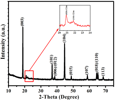
The XRD pattern of the LNMO sample is shown in Fig. 1. All the main reflections are well defined, sharp, and clear, and they are all well indexed to the R![[3 with combining macron]](https://www.rsc.org/images/entities/char_0033_0304.gif) m space group with hexagonal ordering. No impurity peaks exist in the XRD pattern, and the α-NaFeO2 structure is well crystallized.10,25,26 The weak reflections between 20° and 23° confirm the existence of a monoclinic Li2MnO3 phase (space group: C2/m) (inset in Fig. 1), resulting from the superlattice ordering of Li and Mn in the transition metal (TM) layers. The low intensity of these peaks is due to the disorder of LiMn6 clusters with the addition of nickel. The integrated intensity ratio of I(003)/I(104) is larger than 1.2, indicating a low cation mixing in the material. Moreover, the well-separated adjacent reflections (006)/(012) and (018)/(110) in the XRD pattern confirm the well-crystalline layered structure of LNMO material.27–29
m space group with hexagonal ordering. No impurity peaks exist in the XRD pattern, and the α-NaFeO2 structure is well crystallized.10,25,26 The weak reflections between 20° and 23° confirm the existence of a monoclinic Li2MnO3 phase (space group: C2/m) (inset in Fig. 1), resulting from the superlattice ordering of Li and Mn in the transition metal (TM) layers. The low intensity of these peaks is due to the disorder of LiMn6 clusters with the addition of nickel. The integrated intensity ratio of I(003)/I(104) is larger than 1.2, indicating a low cation mixing in the material. Moreover, the well-separated adjacent reflections (006)/(012) and (018)/(110) in the XRD pattern confirm the well-crystalline layered structure of LNMO material.27–29
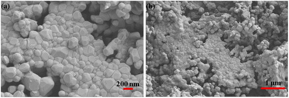
SEM characterization was carried out to study the surface morphology of the LNMO sample. The SEM images indicate that the LNMO powder is made of nanoporous polyhedral particles. The diameter of the particles is in the range of 100–200 nm, with smooth facets and sharp edges (Fig. 2). The decomposition of the precursor components during calcination may be the primary cause of the porous structure. The small particle size shortens the lithium-ion diffusion paths and thereby facilitates its easy transport. The porous structure improves electrolyte infiltration and also provides a large interface area between the LNMO particles, which is believed to promote the Li+ insertion/de-insertion reaction.26
The elemental composition was determined by ICP-AES analysis, which reveals that the Li![[thin space (1/6-em)]](https://www.rsc.org/images/entities/char_2009.gif) :
:![[thin space (1/6-em)]](https://www.rsc.org/images/entities/char_2009.gif) Ni
Ni![[thin space (1/6-em)]](https://www.rsc.org/images/entities/char_2009.gif) :
:![[thin space (1/6-em)]](https://www.rsc.org/images/entities/char_2009.gif) Mn mole ratio in LNMO material is 1.524
Mn mole ratio in LNMO material is 1.524![[thin space (1/6-em)]](https://www.rsc.org/images/entities/char_2009.gif) :
:![[thin space (1/6-em)]](https://www.rsc.org/images/entities/char_2009.gif) 0.242
0.242![[thin space (1/6-em)]](https://www.rsc.org/images/entities/char_2009.gif) :
:![[thin space (1/6-em)]](https://www.rsc.org/images/entities/char_2009.gif) 0.744, which is very close to the theoretical stoichiometry of 1.5
0.744, which is very close to the theoretical stoichiometry of 1.5![[thin space (1/6-em)]](https://www.rsc.org/images/entities/char_2009.gif) :
:![[thin space (1/6-em)]](https://www.rsc.org/images/entities/char_2009.gif) 0.25
0.25![[thin space (1/6-em)]](https://www.rsc.org/images/entities/char_2009.gif) :
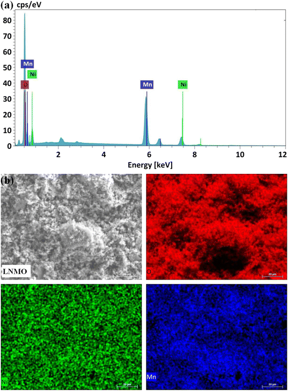
:![[thin space (1/6-em)]](https://www.rsc.org/images/entities/char_2009.gif) 0.75. The results of the EDS analysis (Fig. 3a) show that only Ni, Mn, and O are present on the surface of the LNMO material. Fig. 3b shows the mapping images of Ni, Mn, and O in the LNMO sample by scanning electron microscopy. It confirms that the elements are uniformly distributed in the LNMO material. The surface area of LNMO powder was determined by the BET method, and the obtained specific surface area of the LNMO sample is 12.9 m2 g−1.
0.75. The results of the EDS analysis (Fig. 3a) show that only Ni, Mn, and O are present on the surface of the LNMO material. Fig. 3b shows the mapping images of Ni, Mn, and O in the LNMO sample by scanning electron microscopy. It confirms that the elements are uniformly distributed in the LNMO material. The surface area of LNMO powder was determined by the BET method, and the obtained specific surface area of the LNMO sample is 12.9 m2 g−1.
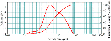
The particle size distribution of the LNMO powder was studied. The results are displayed in Fig. 4, while details of the particle size are summarized in Table 1. The broader particle size distribution curve signifies that the LNMO particles are non-uniformly distributed in the sample, and the particle size (d0.5) is found to be 4.7 μm.
| Sample | d (0.1) | d (0.5) | d (0.9) | d (4,3) |
|---|---|---|---|---|
| LNMO | 1.250 μm | 4.745 μm | 23.357 μm | 9.062 μm |
3.2 Electrochemical evaluation
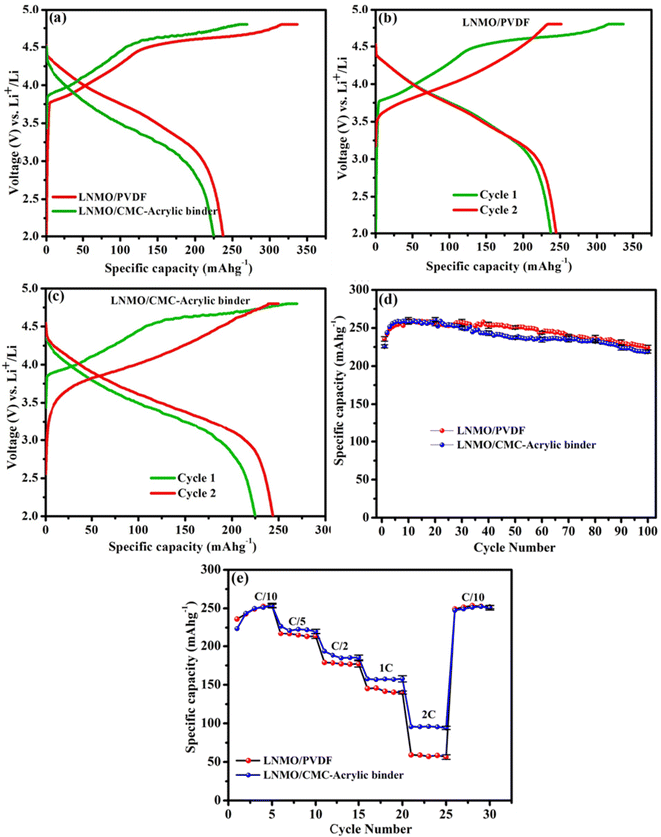
The characteristic initial charge–discharge mechanism is considered the key reason for the high capacity of Li-rich cathode materials. Two coin cells each were assembled and tested to examine the cycling and rate performances. The charge–discharge curves, rate capabilities, and cycling performances of PVDF- and aqueous binder-based electrodes are depicted in Fig. 5a–e. These results are used to examine the effect of the binders on the electrochemical performance of the LNMO material. Fig. 5a represents the initial charge–discharge profiles of the LNMO/PVDF and LNMO/CMC-acrylic binder electrodes. In the initial charging process, two distinct regions are present. The first is a smooth sloping region below 4.5 V, and the second is a long plateau above 4.5 V. The sloping region below 4.5 V is attributed to the lithium-ion extraction from the LiMO2 component with simultaneous oxidation of Ni2+ to Ni4+ ions. The second long plateau above 4.5 V is due to the irreversible release of Li2O from the Li2MnO3 phase to form MnO2.30–32 The smooth sloping curve in the initial discharge process corresponds to Li+ insertion into the crystal structure. The Li+ ions extracted during the initial charging cannot be fully re-inserted into the host structure during the discharge process owing to the dislocation of transition metal (TM) ions after the initial charge process. Thus, the initial discharge capacity is significantly less than the initial charge capacity, leading to a large irreversible capacity loss and a low coulombic efficiency in the first cycle.33–35Fig. 5a revealed that the initial charge–discharge profiles of LNMO electrodes based on both binders are similar. However, above 4.5 V, the charge plateau of the LNMO/CMC-acrylic electrode is shorter than that of the LNMO/PVDF, indicating that it is not easy to extract lithium ions from the Li2MnO3 phase when aqueous binder is employed as a binder in the lithium-rich cathode material. Additionally, the initial discharge capacity of the LNMO-aqueous electrode is 224.94 mA h g−1, whereas that of the PVDF-based electrode is 237.7 mA h g−1. This may be ascribed to the reasonable amount of lithium leaching from LNMO material during aqueous processing. Based on previous reports, it is possible that the leached lithium ions during the electrode process react with phosphate ions from the phosphoric acid, forming Li3PO4, which may act as a barrier to prevent the further loss of lithium from the active material.23,36,37The initial coulombic efficiency of the LNMO/CMC-acrylic electrode is 84.4%, which is much higher than that of the PVDF-based electrode (70.3%). The improved initial efficiency of the LNMO/CMC-acrylic electrode can be explained as follows: during the initial charge process of LNMO material, Li+ ions are extracted from the lithium-rich layer below 4.5 V and form a large number of Li-ion vacancies. When the material is charged to 4.8 V, Li+ ions from the TM layer are extracted in the form of Li2O. Thus, after the first charging, huge lithium-ion vacancies originate in the crystal structure, and the extracted Li+ ions move into the counter electrode through the electrolyte. During the initial discharge process, Na+ ions tend to dissociate from CMC and have the propensity to occupy the Li+ ion vacancies in the TM and Li layer because Na+ ions have a shorter diffusion path than Li+ ions during the discharge process, and it is simpler for Na+ ions in the cathode to enter into Li sites in the cathode structure. The higher radius of Na+ ions than Li+ ions allows the Li layer spacing to be extended after the first cycle. A wider layer gap facilitates the extraction and insertion of Li+ ions, thereby improving the rate performance of the Li-rich cathode.16Fig. 5b and c represent the first and second charge–discharge profiles of LNMO electrodes (based on PVDF and CMC-acrylic binder, respectively), which indicates that the second cycle of the LNMO/CMC-acrylic electrode shows a higher discharge capacity than the PVDF-based electrode (a ∼19 mA h g−1 increase for the LNMO/CMC-acrylic electrode and only a 7 mA h g−1 increase for the LNMO-PVDF electrode). To further study the cyclability (Fig. 5d), cells employing LNMO/CMC-acrylic and LNMO/PVDF electrodes were cycled at C/10 rate for 100 cycles. It is noticeable that LNMO/CMC-acrylic electrodes exhibited a capacity retention of >97.5% at the end of 100 cycles in comparison to the initial discharge capacity, whereas LNMO/PVDF electrode retained a capacity of ∼95.4%. According to reports, the addition of PA during the aqueous processing led to the formation of lithium phosphate and/or transition metal phosphates, which resulted in the formation of a layer of lithium phosphate/transition metal phosphate on the surface of the lithium-rich cathode particle; both are highly insoluble in water and act as a protective layer on the surface of the cathode material.23 Thus, the stabilized electrode/electrolyte interface and the reduction in particle surface reduced the superficial structural degradation of the cathode material, which led to improved rate performance for the LNMO/CMC-acrylic electrode.
Galvanostatic cycling at different C rates, ranging from C/10 to 2C, with five consecutive cycles at each rate, was used to evaluate the rate performance of LNMO cathodes (Fig. 5e). The results indicate that both the CMC-acrylic- and PVDF-processed electrodes exhibit comparable rate performance at lower C rates. However, at 1C and 2C rates, LNMO/CMC-acrylic electrodes exhibited higher capacities than the LNMO/PVDF electrodes. This may be due to the higher Li-ion conductivity offered by Li3PO4 formed during aqueous processing.36,37
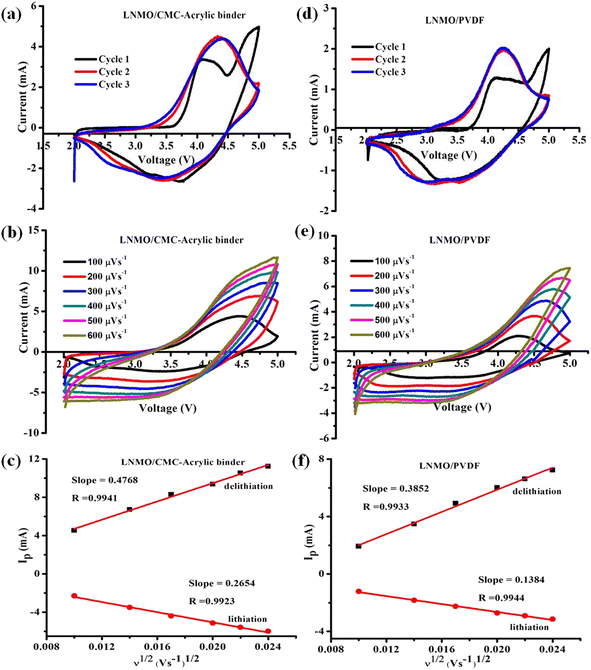
Cyclic voltammetry (CV) studies were carried out to understand how the binder affects the electrochemical performance of LNMO material. The electrochemical behavior of LNMO/PVDF and LNMO/CMC-acrylic electrodes is shown in Fig. 6. Fig. 6a and d show the voltammograms for the half-cells with CMC-acrylic and PVDF-based LNMO, respectively. The voltammograms show a typical intercalation–de-intercalation profile of an LNMO cathode. When swept at 100 μV s−1 in the potential window of 2.0–5.0 V, two anodic peaks were observed in both the systems. Compared to LNMO/PVDF, the first three CV cycles of LNMO/CMC-acrylic-based cells displayed greater peak current densities and reversibility (Fig. 6a). The first anodic peak between 3.5–4 V corresponds to the oxidation of Ni2+ to Ni4+, and the second peak at ∼4.7 V corresponds to the activation of the Li2MnO3 component, in which simultaneous irreversible loss of Li+ and O2− takes place. In the subsequent cycle, there is no oxidation peak at 4.7 V, which confirms that the activation of Li2MnO3 takes place only in the initial cycle and is irreversible.24 The cathodic peak between 3.5 and 4 V indicates the reduction of Ni4+ to Ni2+ ions, and the peak below 3.5 V denotes the reduction of Mn4+ to Mn3+.34 The good overlaps in the second and third cycles of LNMO/CMC-acrylic and LNMO/PVDF electrodes are indicative of stability during the Li+ ion intercalation and de-intercalation processes. Furthermore, the apparent Li+ ion diffusion kinetics were studied by using CV curves at different scan rates (100–600 μV s−1) (Fig. 6b and e). It is evident that when the scan rate increases, the absolute values of the cathodic and anodic peak intensities also increase. The square root of the scan rate and peak current are linearly related in both systems (Fig. 6c and f), and the Randles–Sevcik equation was employed to determine the Li-ion diffusion coefficient (D):38
| Ip = 2.69 × 10⁵n3/2AD1/2CLiν1/2 |
4. Conclusions
In the present study, we have successfully synthesized a lithium-rich cathode material, Li1.5Ni0.25Mn0.75O2.5, via the sol–gel method. The material was characterized by XRD analysis, and the morphology was studied by SEM analysis. Lithium–manganese-rich cathode-based electrodes were fabricated using an aqueous binder consisting of a combination of CMC and acrylic hybrid latex, while phosphoric acid was added to balance the slurry pH value. The electrochemical performance of the aqueous-processed electrodes was compared with that of PVDF-based electrodes. The results indicate that the initial discharge capacity of the PVDF-based electrode (237.7 mA h g−1) is slightly higher than that of the aqueous-processed electrode (224.94 mA h g−1). However, CMC-acrylic-based electrodes exhibit comparable cycling performance at C/10 rate and also show better rate performances at higher rates (1C and 2C). This study proposes a simple and environmentally friendly strategy to improve the electrochemical competence of the electrodes used in the LIBs; thus, it is expected to aid the rapid advancement of the major technological areas in EVs by offering the conceptual basis and essential technical support for developing high-capacity aqueous binder-based cathodes.Conflicts of interest
There are no conflicts to declare.Acknowledgements
Our team greatly acknowledges the Director of Vikram Sarabhai Space Centre, Thiruvananthapuram, for granting permission to publish this paper. Akhilash M. expresses his sincere gratitude to the University of Kerala for granting a Junior Research Fellowship (University of Kerala Registration No. AcEVI(2)/718/CHE/18145/2018).References
- G. Zubi, R. Dufo-López, M. Carvalho and G. Pasaoglu, The Lithium-Ion Battery: State of the Art and Future Perspectives, Renewable Sustainable Energy Rev., 2018, 89, 292–308, DOI:10.1016/j.rser.2018.03.002.
- M. Akhilash, P. S. Salini, B. John and T. D. Mercy, The Renaissance of High-Capacity Cathode Materials for Lithium Ion Cells, in Energy Harvesting and Storage: Fundamentals and Materials, ed. Jayaraj, M. K., Antony, A. and Subha, P. P., Energy Systems in Electrical Engineering, Springer Nature, Singapore, 2022, pp. 181–208, DOI:10.1007/978-981-19-4526-7_6.
- J. M. Tarascon and M. Armand, Issues and Challenges Facing Rechargeable Lithium Batteries, Nature, 2001, 414(6861), 359–367, DOI:10.1038/35104644.
- G. Huang, J. Han, Z. Lu, D. Wei, H. Kashani, K. Watanabe and M. Chen, Ultrastable Silicon Anode by Three-Dimensional Nanoarchitecture Design, ACS Nano, 2020, 14(4), 4374–4382, DOI:10.1021/acsnano.9b09928.
- M. Akhilash, P. S. Salini, B. John, S. Sujatha and T. D. Mercy, Surface Modification on Nickel Rich Cathode Materials for Lithium-Ion Cells: A Mini Review, Chem. Rec., 2023, e202300132, DOI:10.1002/tcr.202300132.
- B. Wu, X. Yang, X. Jiang, Y. Zhang, H. Shu, P. Gao, L. Liu and X. Wang, Synchronous Tailoring Surface Structure and Chemical Composition of Li-Rich–Layered Oxide for High-Energy Lithium-Ion Batteries, Adv. Funct. Mater., 2018, 28(37), 1803392, DOI:10.1002/adfm.201803392.
- A. M. Pillai, P. S. Salini, B. John and M. T. Devassy, Aqueous Binders for Cathodes: A Lodestar for Greener Lithium Ion Cells, Energy Fuels, 2022, 36(10), 5063–5087, DOI:10.1021/acs.energyfuels.2c00346.
- M. S. Whittingham, Lithium Batteries and Cathode Materials, Chem. Rev., 2004, 104(10), 4271–4302, DOI:10.1021/cr020731c.
- M. Akhilash, P. S. Salini, J. Bibin, S. Sujatha and T. D. Mercy, Transition Metal Based Cathode Materials for Lithium-Ion Cells, Transition Metals – an Overview, ed. V. J. Avila, Nova Publisher, 2023, p. 142 Search PubMed.
- M. M. Thackeray, S.-H. Kang, C. S. Johnson, J. T. Vaughey, R. Benedek and S. A. Hackney, Li2MnO3-Stabilized LiMO2 (M = Mn, Ni, Co) Electrodes for Lithium-Ion Batteries, J. Mater. Chem., 2007, 17(30), 3112–3125, 10.1039/B702425H.
- C. S. Johnson, N. Li, C. Lefief and M. M. Thackeray, Anomalous Capacity and Cycling Stability of xLi2MnO3·(1−x)LiMO2 Electrodes (M=Mn, Ni, Co) in Lithium Batteries at 50°C, Electrochem. Commun., 2007, 9(4), 787–795, DOI:10.1016/j.elecom.2006.11.006.
- M. Akhilash, P. S. Salini, B. John and T. D. Mercy, A Journey through Layered Cathode Materials for Lithium Ion Cells – From Lithium Cobalt Oxide to Lithium-Rich Transition Metal Oxides, J. Alloys Compd., 2021, 869, 159239, DOI:10.1016/j.jallcom.2021.159239.
- H. Chen, M. Ling, L. Hencz, H. Y. Ling, G. Li, Z. Lin, G. Liu and S. Zhang, Exploring Chemical, Mechanical, and Electrical Functionalities of Binders for Advanced Energy-Storage Devices, Chem. Rev., 2018, 118(18), 8936–8982, DOI:10.1021/acs.chemrev.8b00241.
- J. Chong, S. Xun, H. Zheng, X. Song, G. Liu, P. Ridgway, J. Q. Wang and V. S. Battaglia, A Comparative Study of Polyacrylic Acid and Poly(Vinylidene Difluoride) Binders for Spherical Natural Graphite/LiFePO4 Electrodes and Cells, J. Power Sources, 2011, 196(18), 7707–7714, DOI:10.1016/j.jpowsour.2011.04.043.
- J.-T. Li, Z.-Y. Wu, Y.-Q. Lu, Y. Zhou, Q.-S. Huang, L. Huang and S.-G. Sun, Water Soluble Binder, an Electrochemical Performance Booster for Electrode Materials with High Energy Density, Adv. Energy Mater., 2017, 7(24), 1701185, DOI:10.1002/aenm.201701185.
- T. Zhao, Y. Meng, R. Ji, F. Wu, L. Li and R. Chen, Maintaining Structure and Voltage Stability of Li-Rich Cathode Materials by Green Water-Soluble Binders Containing Na+ Ions, J. Alloys Compd., 2019, 811, 152060, DOI:10.1016/j.jallcom.2019.152060.
- H. Buqa, M. Holzapfel, F. Krumeich, C. Veit and P. Novák, Study of Styrene Butadiene Rubber and Sodium Methyl Cellulose as Binder for Negative Electrodes in Lithium-Ion Batteries, J. Power Sources, 2006, 161(1), 617–622, DOI:10.1016/j.jpowsour.2006.03.073.
- J. Li, R. B. Lewis and J. R. Dahn, Sodium Carboxymethyl Cellulose: A Potential Binder for Si Negative Electrodes for Li-Ion Batteries, Electrochem. Solid-State Lett., 2006, 10(2), A17, DOI:10.1149/1.2398725.
- P. Zuo, W. Yang, X. Cheng and G. Yin, Enhancement of the Electrochemical Performance of Silicon/Carbon Composite Material for Lithium Ion Batteries, Ionics, 2011, 17(1), 87–90, DOI:10.1007/s11581-010-0494-2.
- P. S. Salini, S. V. Gopinadh, A. Kalpakasseri, B. John and M. Thelakkattu Devassy, Toward Greener and Sustainable Li-Ion Cells: An Overview of Aqueous-Based Binder Systems, ACS Sustainable Chem. Eng., 2020, 8(10), 4003–4025, DOI:10.1021/acssuschemeng.9b07478.
- L. Brückner, J. Frank and T. Elwert, Industrial Recycling of Lithium-Ion Batteries—A Critical Review of Metallurgical Process Routes, Metals, 2020, 10(8), 1107, DOI:10.3390/met10081107.
- Y. Lu, K. Peng and L. Zhang, Sustainable Recycling of Electrode Materials in Spent Li-Ion Batteries through Direct Regeneration Processes, ACS EST Eng., 2022, 2(4), 586–605, DOI:10.1021/acsestengg.1c00425.
- A. Kazzazi, D. Bresser, A. Birrozzi, J. von Zamory, M. Hekmatfar and S. Passerini, Comparative Analysis of Aqueous Binders for High-Energy Li-Rich NMC as a Lithium-Ion Cathode and the Impact of Adding Phosphoric Acid, ACS Appl. Mater. Interfaces, 2018, 10(20), 17214–17222, DOI:10.1021/acsami.8b03657.
- A. M. Pillai, P. S. Salini, B. John, S. Pillai, S. Sarojini Amma and T. D. Mercy, Synthesis and Characterization of Li1.25Ni0.25Mn0.5O2: A High-Capacity Cathode Material with Improved Thermal Stability and Rate Capability for Lithium-Ion Cells, J. Alloys Compd., 2023, 938, 168363, DOI:10.1016/j.jallcom.2022.168363.
- Z. Xiao, J. Meng, Q. Li, X. Wang, M. Huang, Z. Liu, C. Han and L. Mai, Novel MOF Shell-Derived Surface Modification of Li-Rich Layered Oxide Cathode for Enhanced Lithium Storage, Sci. Bull., 2018, 63(1), 46–53, DOI:10.1016/j.scib.2017.12.011.
- M. Akhilash, P. S. Salini, K. Jalaja, B. John and T. D. Mercy, Synthesis of Li1.5Ni0.25Mn0.75O2.5 Cathode Material via Carbonate Co-Precipitation Method and Its Electrochemical Properties, Inorg. Chem. Commun., 2021, 126, 108434, DOI:10.1016/j.inoche.2020.108434.
- J. Bareño, C. H. Lei, J. G. Wen, S.-H. Kang, I. Petrov and D. P. Abraham, Local Structure of Layered Oxide Electrode Materials for Lithium-Ion Batteries, Adv. Mater., 2010, 22(10), 1122–1127, DOI:10.1002/adma.200904247.
- L. Ku, Y. Cai, Y. Ma, H. Zheng, P. Liu, Z. Qiao, Q. Xie, L. Wang and D.-L. Peng, Enhanced Electrochemical Performances of Layered-Spinel Heterostructured Lithium-Rich Li1.2Ni0.13Co0.13Mn0.54O2 Cathode Materials, Chem. Eng. J., 2019, 370, 499–507, DOI:10.1016/j.cej.2019.03.247.
- A. M. Pillai, P. S. Salini, B. John, V. S. Nair, K. Jalaja, S. SarojiniAmma and M. T. Devassy, Cobalt-Free Li-Rich High-Capacity Cathode Material for Lithium-Ion Cells Synthesized through Sol–Gel Method and Its Electrochemical Performance, Ionics, 2022, 28(11), 5005–5014, DOI:10.1007/s11581-022-04725-x.
- L. Li, B. H. Song, Y. L. Chang, H. Xia, J. R. Yang, K. S. Lee and L. Lu, Retarded Phase Transition by Fluorine Doping in Li-Rich Layered Li1.2Mn0.54Ni0.13Co0.13O2 Cathode Material, . Journal of Power Sources, 2015, 283, 162–170, DOI:10.1016/j.jpowsour.2015.02.085.
- J. Zheng, S. Myeong, W. Cho, P. Yan, J. Xiao, C. Wang, J. Cho and J.-G. Zhang, Li- and Mn-Rich Cathode Materials: Challenges to Commercialization, Adv. Energy Mater., 2017, 7(6), 1601284, DOI:10.1002/aenm.201601284.
- M. Akhilash, P. S. Salini, B. John, N. Supriya, S. Sujatha and T. D. Mercy, Thermal Stability as Well as Electrochemical Performance of Li-Rich and Ni-Rich Cathode Materials—a Comparative Study, Ionics, 2023, 29, 983–992, DOI:10.1007/s11581-022-04873-0.
- F. Li, Y. Y. Sun, Z. H. Yao, J. S. Cao, Y. L. Wang and S. H. Ye, Enhanced Initial Coulombic Efficiency of Li1.14Ni0.16Co0.08Mn0.57O2 Cathode Materials with Superior Performance for Lithium-Ion Batteries, Electrochim. Acta, 2015, 182, 723–732, DOI:10.1016/j.electacta.2015.08.163.
- A. Mohanan Pillai, P. S. Salini, B. John, J. T, S. SarojiniAmma and M. Thelakkattu Devassy, Synthesis and Electrochemical Characterization of a Li-Rich Li1.17Ni0.34Mn0.5O2 Cathode Material for Lithium-Ion Cells, Energy Fuels, 2022, 36(18), 11186–11193, DOI:10.1021/acs.energyfuels.2c01231.
- A. M. Pillai, P. S. Salini, B. John, C. Suchithra, S. SarojiniAmma and M. T. Devassy, Lithium-Rich Li1.17Ni0.17Co0.17Mn0.5O2 Cathode Material for Lithium-Ion Cells: Effect of Calcination Temperature on Electrochemical Performance, Energy Fuels, 2023, 37(18), 14334–14340, DOI:10.1021/acs.energyfuels.3c02174.
- M. Kuenzel, D. Bresser, T. Diemant, D. V. Carvalho, G.-T. Kim, R. J. Behm and S. Passerini, Complementary Strategies Toward the Aqueous Processing of High-Voltage LiNi0.5Mn1.5O4 Lithium-Ion Cathodes, ChemSusChem, 2018, 11(3), 562–573, DOI:10.1002/cssc.201702021.
- N. Loeffler, G.-T. Kim, F. Mueller, T. Diemant, J.-K. Kim, R. J. Behm and S. Passerini, In Situ Coating of Li[Ni0.33Mn0.33Co0.33]O2 Particles to Enable Aqueous Electrode Processing, ChemSusChem, 2016, 9(10), 1112–1117, DOI:10.1002/cssc.201600353.
- S.-L. Cui, X. Zhang, X.-W. Wu, S. Liu, Z. Zhou, G.-R. Li and X.-P. Gao, Understanding the Structure–Performance Relationship of Lithium-Rich Cathode Materials from an Oxygen-Vacancy Perspective, ACS Appl. Mater. Interfaces, 2020, 12(42), 47655–47666, DOI:10.1021/acsami.0c14979.
| This journal is © The Royal Society of Chemistry 2024 |

