 Open Access Article
Towards sustainable TiO2 photoelectrodes based on cellulose nanocrystals as a processing adjuvant†
C.
Martínez-Barón
 a,
V.
Calvo
 a,
J.
Hernández-Ferrer
 a,
B.
Villacampa
 b,
A.
Ansón-Casaos
 a,
J. M.
González-Domínguez
 *a,
W. K.
Maser
 a and
A. M.
Benito
 a
a
aInstituto de Carboquímica, ICB-CSIC, Miguel Luesma Castán 4, 50018 Zaragoza, Spain. E-mail: jmgonzalez@icb.csic.es
bDepartamento de Física de la Materia Condensada, INMA-CSIC, Universidad de Zaragoza, 50009, Zaragoza, Spain
First published on 4th June 2024
Abstract
Photoelectrodes of TiO2 in the form of films are commonly fabricated using screen printing techniques, employing viscous commercial TiO2 pastes. However, these pastes comprise environmentally unfriendly, multicomponent formulations designed to manufacture the photoactive TiO2 nanoparticles. To strive for sustainable processing and pave the way for the use of liquid-phase film processing technologies, the inherent limited water dispersibility of TiO2 nanoparticles must be overcome. In this study, we show that cellulose nanocrystals, produced via an environmentally benign one-pot hydrolysis process, enable the preparation of stable TiO2 water dispersions. The remarkable stability of these dispersions, evidenced by their outstanding ξ-potential values of −34 mV, facilitates the fabrication of macroporous TiO2 photoactive films throughout spray coating. Employed as photoanodes in a photoelectrochemical cell, our TiO2 photoanodes are compared with conventional TiO2 electrodes obtained from commercial pastes under water splitting conditions. Interestingly, our photoanodes reveal a remarkable three-fold enhancement of the photocurrent performance (132 vs. 46 μA cm−2) and a four-fold increase in the on–off response rate (4 vs. 1 s). These findings underscore the valuable role of cellulose nanocrystals as a green processing asset for achieving TiO2 water dispersions. Moreover, they serve as sacrificial adjuvants for preparing highly macroporous and functional film photoelectrodes, representing a significant step forward in the pursuit of sustainable and efficient materials processing.
Sustainability spotlightPhotoelectrochemical processes are essential for many clean energy production methods. For such purpose, the involved electrodes are typically fabricated by means of polluting additives and toxic solvents. Designing efficient electrodes in a sustainable way is of fundamental interest. There is thus a need for non-toxic and green aqueous dispersants, for which nanocellulose shows promising prospects of sustainability and cost-effectiveness. Here we use cellulose nanocrystals in combination with TiO2 nanoparticles, not only to valorise renewable raw materials, but also to conform functional photoanodes in a ground-breaking way. These electrodes are able to undergo photoelectrochemical water splitting, performing more efficiently than a commercial TiO2 benchmark due to the role of nanocellulose, which goes beyond a mere dispersing agent. Our methodology addresses important aspects of responsible consumption and production (UN SDG 12), affordable and clean energy (UN SGD 7), and climate action (UN SDG 13). |
1. Introduction
Titanium dioxide (TiO2) is a widely studied photoactive semiconducting metal oxide of special interest in photocatalysis,1 dye-sensitized solar cells,2,3 and photoelectrochemical (PEC) applications.4 In particular, PEC water splitting is a technology that combines both solar energy and electrochemistry to produce hydrogen by the photoelectrolysis of water.5,6 For such purpose, TiO2 materials should be previously processed into photoactive films over a conductive substrate, rendering TiO2 photoelectrodes. One of the most employed procedures for depositing TiO2 into films for PEC applications is by means of highly viscous pastes, almost completely limiting the deposition methodology to screen printing. In such commercial pastes, TiO2 is generally mixed with organic solvents, binders and additives such as acetonitrile, terpineol, or ethyl- and carboxymethyl cellulose,7 whose synthesis conditions and overall preparation procedure may be considered non environmentally friendly.8,9 On the contrary, the rather challenging issue of developing stable aqueous TiO2 dispersions not only would offer a more desirable green alternative route, but also enables an environmentally friendlier fabrication of photoelectrodes, compatible with large area liquid processing techniques, such as spray coating.Within this context, an emerging trend based on the use of nanostructures from a natural origin (i.e., derived from biopolymers) as processing adjuvants for carbon nanomaterials, is growing steep. In particular, cellulose nanocrystals (CNC) have attracted an increasing level of attention in the materials community. These nanostructures, derived from cellulose, the most abundant biopolymer on Earth, serve as paradigm of a truly sustainable entry to nanotechnology,10 by virtue of their inherent renewability and hydrophilicity, stemming from their size and morphology.11 The outstanding versatility of CNC is the reason behind the wide range of fields in which it is being used, namely biomedicine,12 wastewater treatment,13 or green hydrogen production.14 To achieve such landmark results, the aqueous dispersive ability of CNC is a key property, enabling an environmentally friendly processing for many otherwise water-insoluble nanomaterials. In particular, the dispersion of carbon nanomaterials by action of CNC in water is the pinnacle of this strategy, to which we have recently reported significant advances in the field of water-based carbon nanotube inks with high colloidal stability, tunable consistence and composition, facile workability and potential applications in the field of electronics,15 biosensing,16 energy storage,17 and biomedicine.18,19
In this work, we explore the use of CNC which show promise to establish electrostatic interactions with TiO2 nanoparticles (TiO2-NPs), rendering stable water dispersions. CNC can be synthesized in any of their two most common crystalline allomorphs, types I (with parallel chain arrangement), and II (antiparallel chains). We have focused on type II CNC for several reasons. Particularly, our experimental procedure for the synthesis of type II CNC is based in a one-pot acid hydrolysis.18,20 The main advantage of the chosen procedure with respect to other methods is that it only uses a single H2SO4 treatment to microcrystalline cellulose, and as a result is a shorter and environmentally-friendlier method compared to TEMPO-mediated oxidation or mercerization.20 The one-pot acid hydrolysis also entails the retention of sulfate ester groups on the type II CNC surface, which can be up to double compared to type I CNC,21 and could be removed if an eventual mercerization step were applied.22 It is the presence of the sulfate ester groups, which thus renders a type II CNC of potential interest for establishing interactions with TiO2, promoting its water dispersibility.
We also herein show that such waterborne TiO2-CNC-II colloidal systems can be readily processed by spray coating into film photoelectrodes. Employed as the photoanode in a PEC cell under water-splitting conditions we compare its performance with a photoanode fabricated from a commercial TiO2 paste. Properties of the developed materials, dispersions and films are studied in detail and compared to those of the commercial paste, providing insights into the beneficial action of CNC for dispersing TiO2-NPs and the enhanced operational performance of photoelectrodes obtained thereof.
2. Experimental
2.1 Materials and reagents
The cellulose source employed was microcrystalline cellulose (MCC) derived from cotton linters in powdered form with an average particle size of 20 μm (Sigma-Aldrich, ref 310697). Sulfuric acid (H2SO4, 98%) was acquired from Labkem (Barcelona, Spain). Boric acid (H3BO3, 99.9%) was purchased from a local provider. Isopropanol (<99.8%) and ammonium hydroxide (NH4OH, 30%) were acquired from Panreac. Any reported use of water corresponds to ultrapure water from a Siemens Ultraclear device, with a conductivity of 0.055 μS cm−1. Titanium(IV) isopropoxide, TTIP (97%, 205273) was purchased from Sigma-Aldrich. A commercial TiO2 paste was purchased from GreatCell Solar (18 NR-AO). Asahi fluorinated tin oxide (FTO)-coated glass substrates (70–100 Ω sq−1, 80 nm thick) cut in 2.5 × 1 cm pieces were supplied by Solems (Palaiseau, France).2.2 Sample preparation
![[thin space (1/6-em)]](https://www.rsc.org/images/entities/char_2009.gif) :
:![[thin space (1/6-em)]](https://www.rsc.org/images/entities/char_2009.gif) 1) mixture containing 5 mg of boric acid. The resulting gel was aged overnight under constant magnetic stirring, vacuum-filtered, and dried in an oven at 80 °C. The as-prepared amorphous TiO2 was then thermally treated in a horizontal quartz reactor under an air atmosphere at 550 °C for 30 min to induce the crystallization of the anatase phase.
1) mixture containing 5 mg of boric acid. The resulting gel was aged overnight under constant magnetic stirring, vacuum-filtered, and dried in an oven at 80 °C. The as-prepared amorphous TiO2 was then thermally treated in a horizontal quartz reactor under an air atmosphere at 550 °C for 30 min to induce the crystallization of the anatase phase.
2.3 Characterization techniques
X-ray diffraction (XRD) patterns of powder materials were collected with a Bruker D8 Advance diffractometer using a Cu tube as the X-ray source (λ CuKα = 1.54 Å), a tube voltage of 40 kV, and a current of 40 mA. The results were recorded in Bragg–Brentano geometry in the range of 2θ = [5–40°], with steps of 0.05° and 3 s accumulation time.Particle size and ζ-potential were measured in a Malvern Nano ZS instrument, employing the principles of dynamic light scattering (DLS) and electrophoresis. To this end, TiO2 dispersions were diluted in water (1![[thin space (1/6-em)]](https://www.rsc.org/images/entities/char_2009.gif) :
:![[thin space (1/6-em)]](https://www.rsc.org/images/entities/char_2009.gif) 50) with respect to their initial concentration. For the DLS measurements, a refractive index of 2.52 for TiO2 (anatase) was considered. Measurements were performed at room temperature (25 °C) in triplicate and are referred to a typical pH of 6.5 (TiO2–CNC dispersions) or 6.7 (TiO2–CNC(NH4OH) dispersions).
50) with respect to their initial concentration. For the DLS measurements, a refractive index of 2.52 for TiO2 (anatase) was considered. Measurements were performed at room temperature (25 °C) in triplicate and are referred to a typical pH of 6.5 (TiO2–CNC dispersions) or 6.7 (TiO2–CNC(NH4OH) dispersions).
Transparency of the waterborne TiO2 dispersions was assessed by measuring the UV-vis transmittance spectra in 3 mL quartz cuvettes using a Shimadzu UV-2401PC spectrophotometer. Prior to the measurement, dispersions were diluted 1![[thin space (1/6-em)]](https://www.rsc.org/images/entities/char_2009.gif) :
:![[thin space (1/6-em)]](https://www.rsc.org/images/entities/char_2009.gif) 50 times in water. In order to determine the stability of the dispersions, transmittance was evaluated at a fixed wavelength for different times.
50 times in water. In order to determine the stability of the dispersions, transmittance was evaluated at a fixed wavelength for different times.
Thickness and surface roughness of supported film photoelectrodes were evaluated by using a contact DektakXT Stylus Profiler (from Bruker, Billerica, MA, USA). The radius of the stylus tip was 2.5 μm. The height of the step of each deposited layer was measured at different areas along the layer edge. The depths of grooves made in the central part of the sample (reaching the substrate) were also determined. The layer thickness was obtained as the mean value of such measurements. The profile roughness was analyzed using Dektak analytical software (from Bruker, Jena, Germany).
Transmission electron microscopy (TEM) images were collected for all the TiO2 dispersions using a Tecnai T20 (Thermofisher) at 200 kV. Dispersions were deposited onto lacey carbon coated TEM copper grids (CF400-CU, 50/pk) supplied by Aname.
Scanning electron microscopy (SEM) images of the TiO2 photoanodes were taken using a Hitachi S3400N equipment (Tokyo, Japan), working in the secondary electron mode at a voltage of 15 kV and a distance of 5 mm.
2.4 Photoelectrochemical (PEC) measurements
PEC measurements were carried out in a three-electrode cell, using a 150 W Xe arc lamp from LOT-Oriel (Quantum Design Europe, Germany) that provided a light power intensity of 100 mW cm−2 (AM 1.5G filter) at the distance of the target electrode. A monochromator (LOT Oriel MSH-300) is utilized to study the photocurrent as a function of the incident wavelength. The employed PEC cell consisted of a glass container with a quartz window, the Ag/AgCl electrode as the reference and a graphite bar as the counter electrode. The electrolyte was a 0.1 M Na2SO4 aqueous solution. The cell was purged with N2 for 15 min before the measurement. Cyclic voltammetry (CV) experiments were performed in the range of −1.1 to 0.4 V, starting at 0.4 V, both in the dark and under irradiation conditions. On/off transient photocurrent experiments and Incident Photon to Current Efficiency (IPCE) measurements were performed at a constant voltage of 0 V (vs. Ag/AgCl). Open Circuit Potential (OCP) measurements were conducted forcing zero intensity. Electrochemical impedance spectroscopy (EIS) experiments were carried out from 105 to 10−2 Hz at 0 V (vs. Ag/AgCl) both in the dark and under irradiation.3. Results and discussion
TiO2 is a well-known semiconductor widely used in photocatalytic and PEC applications. However, its inherent insolubility and non-processability in water pose substantial challenges. For the development of TiO2 photoactive films, commercial pastes containing alkylated celluloses and other organic compounds are commonly employed, entailing multicomponent and environmentally unfriendly formulations. Moreover, due to the high viscosity of these pastes, fabrication of films is generally limited to the use of screen-printing technologies. With a view to develop greener water-based TiO2 formulations and to expand its applicability to more convenient large-area film processing, we propose the use of CNC for stabilizing TiO2-NPs in water. CNC, with their potential to establish favourable interactions, particularly with inherently hydrophobic carbon nanostructures,23 offer a unique opportunity to address the challenge of preparing aqueous TiO2-NPs dispersions.16,18,23,24 Our dispersing strategy for TiO2-NPs relies on CNC in its type II crystalline allomorph, synthesized by acidic hydrolysis, avoiding the need for mercerization steps.20 This greener protocol enables the retention of a significant number of negatively charged sulphate ester groups on its skeleton,25 responsible for their high aqueous colloidal stability. Consequently, this strategy should provide promising pathways for stablishing electrostatic interactions with TiO2-NPs, thereby enabling their effective dispersion in water.Accordingly, TiO2-NPs were dispersed in water with the assistance of type-II CNC as dispersing agent. DLS and ζ-potential measurements were carried out for the employed dispersions (ESI, Table 1 and Fig. S4†). Notably, the hydrodynamic radius (RH) of the colloidal particles in the TiO2–CNC dispersions exhibits a slight decrease compared to the bare type-II CNC aqueous colloids, which typically reveal values between 400 to 500 nm.18,20 This observation suggests the establishment of favorable interactions between TiO2 and CNC, which simultaneously promote the disaggregation of the hybrid material. Moreover, previous studies have highlighted the significance of pH in governing the stability of cellulose nanocrystal dispersions,26 cellulose derivatives,27 as well as of TiO2 colloids,28 underlining the convenience of higher pH values to attain more stable colloids. Accordingly, a slight alkalization of the TiO2–CNC system using NH4OH was employed to further enhance the stability of the dispersion. This alkalization resulted in a decrease of the average RH, indicating further disaggregation of the suspended TiO2–CNC(NH4OH) hybrids. Additionally, ζ-potential measurements served as a direct assessment of the colloidal stability based on electrostatic interactions. The ζ-potential of TiO2–CNC dispersions exceeds 20 mV in absolute value, implying an incipient level of stability in the achieved aqueous dispersion. The alkalization of this colloidal system, yielding the TiO2–CNC(NH4OH) variant, leads to an enhancement of the ζ-potential by 10 mV in absolute value, hence entering in a range characteristic of stable dispersions.29 While the presence of CNC is key for initially achieving TiO2-NPs stably suspended in water at neutral pH, the addition of NH4OH synergistically results in dispersions characterized by smaller particle sizes and enhanced electrostatic potentials, thus providing a more favorable scenario (ESI, Table S2†).
| TiO2 | CNC | TiO2–CNC | TiO2–CNC(NH4OH) | |
|---|---|---|---|---|
| R H (nm) | 380 ± 15 | 252 ± 8 | 159 ± 3 | 115 ± 3 |
| ζ-Potential (mV) | −16.0 ± 0.6 | −25 ± 2 | −24.1 ± 0.1 | −34 ± 1 |
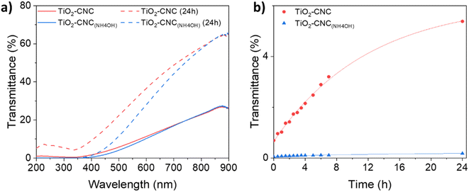
The time-dependent stability of the TiO2–CNC dispersions was further assessed by UV-Vis transmittance spectroscopy (Fig. 2). For these analyses two key considerations are taken into account. Firstly, an increase in transmittance over time indicates a loss of colloidal stability. Secondly, two distinct phenomena affect the transparency in the UV-Vis spectra: light absorption and scattering. Specifically, TiO2 exhibits significant light absorption in the near-UV range, while scattering contributes both to visible and UV regions. Hence, a wavelength of 360 nm was selected for the transmittance analysis, as it measures the combined effects of scattering and absorption exhibited by the suspended particles. The transmittance spectra of both TiO2 dispersions (Fig. 2a) displayed minimal values in the range of 300 to 350 nm, due to the absorption of TiO2. Initially, the transmittance of both dispersions was nearly identical. However, after 24 hours, noticeable differences in their spectra emerged, highlighting the synergistic effect of NH4OH and CNCs in stabilizing the TiO2-NPs over extended periods of time (ESI, Fig. S5†). Fig. 2b displays the evolution of transmittance with time at the selected wavelength of 360 nm. Notably, the TiO2–CNC(NH4OH) dispersion exhibits the highest stability, as the transmittance values remained practically unchanged even after 24 hours, thus further evidencing the remarkable in-time stability achieved through the additional use of NH4OH.
Transmission electron microscopy (TEM) analysis (Fig. 3) provided valuable insights into the morphology both of TiO2–CNC systems and interactions between components. Examination of the freeze-dried materials obtained from each TiO2 dispersion unveiled the presence of TiO2-NPs (dark contrast) with an average diameter of 25 nm. These nanoparticles form aggregates with sizes ranging from 300 to 400 nm tethered of rod-like CNC, which individually exhibited a length of about 50 nm and a diameter around 5 nm. The CNC aggregates reveal sizes of approximatively 100 nm. Both components exhibit close contact with each other, with minimal presence of free TiO2 or CNC. Interestingly, differences were noted between the two systems. In the TiO2–CNC material (Fig. 3a), the aggregates were notably larger compared to those observed in the TiO2–CNC(NH4OH) hybrid (Fig. 3c and d). These observations are in line with those derived from DLS measurements. Furthermore, the coverage differed between the systems. In the non-alkalized TiO2–CNC hybrid, TiO2-NPs tended to form agglomerates on the surface of CNC, leaving large areas of CNC uncovered (Fig. 3b). By contrast, the TiO2–CNC(NH4OH) hybrid exhibited smaller sizes, thus leading to a higher level of interaction between both components (Fig. 3c and d). These observations suggest that ammonia not only contributes to improve the dispersion of both TiO2-NPs and CNC, resulting in less aggregated materials (ESI, Fig. S6†), but also enhances the interaction between the components, leading to a more defined hybrid material.
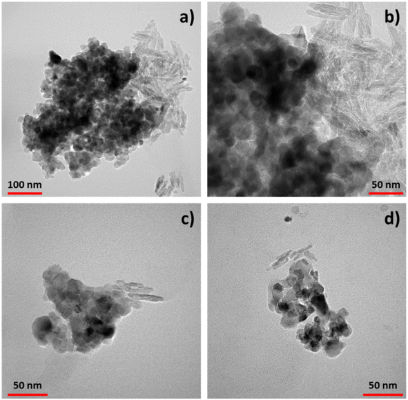 | ||
| Fig. 3 TEM images of the TiO2–CNC hybrids. (a) TiO2–CNC aggregates and (b) zoom in. (c) and (d) Different aggregates of TiO2–CNC(NH4OH). | ||
Based on these findings, the TiO2–CNC(NH4OH) hybrid was chosen for the film fabrication of TiO2 photoanodes. The TiO2–CNC(NH4OH) ink was spray-coated onto FTO substrates and the resulting films were characterized. Particularly, the TiO2![[thin space (1/6-em)]](https://www.rsc.org/images/entities/char_2009.gif) :
:![[thin space (1/6-em)]](https://www.rsc.org/images/entities/char_2009.gif) CNC ratio of the employed inks was 1
CNC ratio of the employed inks was 1![[thin space (1/6-em)]](https://www.rsc.org/images/entities/char_2009.gif) :
:![[thin space (1/6-em)]](https://www.rsc.org/images/entities/char_2009.gif) 1. Morphology of the prepared films was examined by scanning electron microscopy (SEM) before and after the applied sintering process (Fig. 4).
1. Morphology of the prepared films was examined by scanning electron microscopy (SEM) before and after the applied sintering process (Fig. 4).
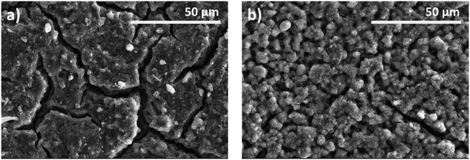 | ||
| Fig. 4 SEM images at different stages of the employed TiO2 photoanodes. (a) TiO2–CNC(NH4OH) electrode before sintering, (b) TiO2–CNC(NH4OH) electrode after sintering. | ||
Specifically, Fig. 4a shows a densely packed film with multiple fissures resulting from the spray coating process. Upon air sintering, the film underwent a remarkable morphological transformation, acquiring a highly macroporous structure, related to the complete removal of CNCs from the TiO2 matrix (Fig. 4b). The complete elimination of CNC was corroborated by dynamic TGA analysis (ESI, Fig. S7†). In particular, CNC were almost completely eliminated in the TiO2–CNC material at 450 °C under an air atmosphere (ESI, Fig. S8†). Therefore, it can be deduced that CNC have been completely removed from the TiO2 matrix during the sintering step (450 °C, 2 hours). Thus, the complete removal of CNC facilitates the formation of a macroporous film. Physisorption isotherms and profilometry studies (see ESI, Fig. S9–S13†) support the effect of CNC removal regarding bulk porosity and film surface, respectively.
Next, the TiO2–CNC(NH4OH) films were used as photoanode for the oxidation of water. Their photoelectrochemical performance was compared against the one of a reference photoanode fabricated from a commercial TiO2 paste (TiO2–P). Full details on the TiO2–P film fabrication and characterization are provided in the ESI (Fig. S3).† Basically, XRD reveals that the paste has the same crystalline phase than pristine TiO2-NPs (anatase, ESI, Fig. S14†), while having a somewhat higher TiO2 concentration (63%, ESI, Fig. S15†) to that of the TiO2–CNC(NH4OH) hybrids (50%, ESI, Fig. S8†) according to the TGA results.
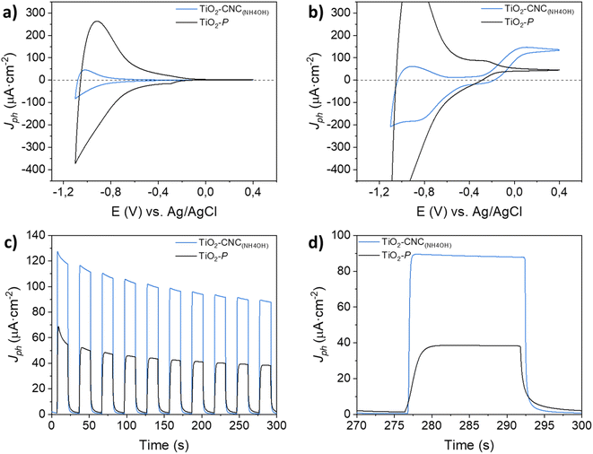
Cyclic voltammetry (CV) measurements in the dark (Fig. 5a) exhibited a cathodic current as the potential shifted towards negative values, accompanied by a nearly symmetric positive current during the reverse scan. These currents originate from the filling and emptying of electronic states in nanoparticulate TiO2, resulting in an accumulation region that characterizes the capacitive behavior of the film.30 Both photoanodes display an accumulation region at approximately −0.8 V, and a depletion region at higher potentials (−0.4 V), in agreement with literature.31 The differences in capacitance between the films prepared from TiO2–CNC(NH4OH) inks and the commercial TiO2–P pastes are attributed not only to their TiO2 content but also to their distinct morphological characteristics. The TiO2–P based films weighted 0.6 mg of TiO2 while exhibiting a smooth surface (ESI, Fig. S16†). Moreover, the TiO2–CNC(NH4OH)-based films weighted 0.4 mg of TiO2 and revealed a highly macroporous morphology (Fig. 4). Profilometry analysis further revealed a more pronounced roughness of the TiO2–CNC(NH4OH) compared to the TiO2–P films (see Fig. S9 and S10 in ESI†). Under light irradiation (Fig. 5b), a water photooxidation current is observed at potentials higher than −0.3 V, exhibiting positive current densities that are in line with the typical behavior of TiO2 electrodes.32 Notably, the TiO2–CNCs(NH4OH) photoanode revealed a three-fold higher photocurrent value (132 μA cm−2) compared to the TiO2–P photoanode (46 μA cm−2) at 0 V (vs. Ag/AgCl). Additional features associated with the photogeneration of charges were evident in the cathodic scan of TiO2–CNC(NH4OH) photoanode between −0.7 V and −1.2 V.
In order to validate the superior water oxidation activity of the TiO2–CNC(NH4OH) electrode, transient photocurrent measurements at a constant potential of 0 V (vs. Ag/AgCl) were carried out (Fig. 5c and d). In the same way, the TiO2–CNC(NH4OH) photoanode shows a remarkable enhancement in photocurrent by a factor of 2.5, compared to the TiO2–P photoanode. This significant improvement in water oxidation performance can be partially attributed to the removal of CNC from the TiO2 matrix during the sintering step, causing an enhanced accessibility of the electrolyte to the TiO2 active sites. This remarkable effect highlights an additional role of CNC serving as a sacrificial adjuvant, contributing to an enhanced PEC performance (see ESI, Fig. S17 and S18†). Importantly, the development of film roughness is not observed in the commercial TiO2 paste (see SEM and profilometry results in ESI, Fig. S9, S10 and S16†), which contains other types of cellulose derivatives, such as carboxymethyl or ethyl cellulose. Furthermore, during the 5 minutes transient photocurrent measurements, both electrodes display a decay in photocurrent (Fig. 5c), typically ascribed to the blocking of TiO2 surface states caused by parasitic redox processes (see ESI, Fig. S19† for a 5 hours photocurrent measurement).33–35 The photoelectrochemical response of the TiO2–CNC(NH4OH) electrode exhibits a significantly faster response upon switching the light irradiation from on to off states compared to the one prepared from the commercial TiO2–P paste (Fig. 5d). Notably, the steady state was reached within 1 second for the TiO2–CNC(NH4OH) electrode under both dark and light pulses, whereas the TiO2–P photoanode required 4 seconds. This clear distinction in response time further underscores the significant impact of the TiO2-NPs processing with CNC, which results in a photoanode with lower recombination losses.36
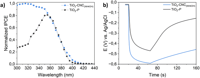
Aiming to further evaluate the relationships between the chosen processing and PEC performance, IPCE and OCP measurements were carried out. Fig. 6a displays the normalized IPCE of both TiO2–CNC(NH4OH) and TiO2–P photoanodes recorded at 0 V (vs. Ag/AgCl). The TiO2–CNC(NH4OH) photoanode exhibited an enhanced UV response, as well as a slight light absorption shift towards the visible range respect to the TiO2–P electrode. Thus, it can be stated that the processing of TiO2-NPs with CNC leads to photoactive films with enhanced PEC activity. As such, the OCP experiments shown in Fig. 6b revealed that the TiO2–CNC(NH4OH) photoanode was readily polarized upon irradiation (VOCP = −0.59 V) when compared to the TiO2–P (VOCP = −0.46 V). Interestingly, the open circuit photopotential of the TiO2–CNC(NH4OH) reveals a significantly slower response upon switching off the light off (t = 65 s), compared to the one of TiO2–P, thus suggesting a larger carrier lifetime.31 These key findings are in line with the improved PEC performance and faster response shown in Fig. 5, which are directly related to the kinetics of the process.
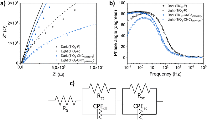
Electrochemical impedance spectroscopy (EIS) was conducted on both TiO2–CNC(NH4OH) and TiO2–P photoanodes to evaluate the interfacial properties between the photoelectrodes and the electrolyte. Fig. 7a shows the Nyquist plots of both photoanodes measured in dark and illumination conditions. The arc diameters obtained for both electrodes are larger in the absence of light, indicating a reduced resistance to the charge transference during irradiation. Interestingly, the TiO2–CNC(NH4OH) photoelectrode exhibits smaller arc radius under both dark and irradiation conditions compared to that of the photoelectrode obtained from the commercial TiO2–P paste, evidencing a lower charge-transfer resistance and thus a superior charge transfer efficiency within the electrode and toward the electrolyte. In the Bode phase plots (Fig. 7b), a similar behavior to other previously measured TiO2 materials can be observed.37
The EIS data were fitted to an equivalent circuit (Fig. 7c and S20, in ESI†) commonly employed for the description of semiconductor electrodes.38 This circuit consists of a series resistance (RS) and two RC elements in series, each consisting of a resistance (Rct or Rsc) in parallel with a constant phase element (CPEdl or CPEsc). The RS parameter includes the resistance of the substrate (FTO) and the external contact resistance. The first RC element is attributed to TiO2/electrolyte interface, and is described by the parallel elements (Rct, CPEdl), while the second RC, which can be tentatively attributed to faster processes, such as TiO2/FTO interface, or TiO2 space-charge behavior, was modeled with (Rsc, CPEsc) elements. The impedance spectra of both photoanodes fitted well to the proposed equivalent circuit, irrespective of the nature of the TiO2 material. Capacitance values Cdl and Csc were obtained from CPEdl and CPEsc using eqn (S1) (see ESI).† Numerical calculations were employed to determine the model parameters, which are listed in Table 2. The differences in RS values can be attributed to various factors, including the impact of sintering steps on the FTO conductive substrate, and the ohmic drops resulting from the electrode contact with the potentiostat. Notably, under light irradiation, the TiO2–CNC(NH4OH) photoanode exhibits a significantly smaller Rct value compared to the reference photoanode, indicating faster charge transfer process from the TiO2 film to the electrolyte. Additionally, the Cdl constant phase element values showed a slight increase upon illumination for both electrodes, which might be related to the generation of excitons when light interacts with the photoanode, leading to an increased concentration of charge carriers on the TiO2 electrode surface. Furthermore, Rsc values were relatively higher in the TiO2–CNC(NH4OH) photoanode, likely stemming from contact issues between the TiO2 film and FTO, which in turn, could be related to differences in the film fabrication process, i.e. a factor not based on intrinsic materials properties. Finally, the Csc values, associated with processes at the TiO2 bulk, or TiO2/FTO interface, remained similar in both cases, probably due to the crystallographic similarity between the two TiO2 starting materials.
| Photoanode | R S (Ω) | R ct (Ω) | R sc (Ω) | C dl (μF) | C sc (μF) |
|---|---|---|---|---|---|
| TiO2–CNC(NH4OH) (dark) | 302 | 8.6 × 10⁵ | 60 | 16 | 4 |
| TiO2–CNC(NH4OH) (light) | 318 | 7.1 × 10⁴ | 32 | 23 | 4 |
| TiO2–P (dark) | 128 | 1.1 × 10⁶ | 17 | 19 | 7 |
| TiO2–P (light) | 129 | 2.5 × 10⁵ | 8 | 21 | 5 |
Thus, the use of CNC for dispersing TiO2-NPs not only provided successful stabilization of the aqueous TiO2 dispersion, but also played a crucial role in improving the photocatalytic activity of the resulting electrodes.
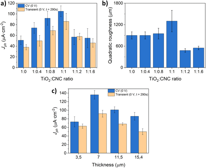
Subsequently, to maximize the water oxidation activity of the as-prepared TiO2 photoelectrodes, a series of experiments were conducted by adjusting the relative proportion of CNC to TiO2-NPs and ammonia in the aqueous dispersion. Fig. 8a displays the photocurrent values obtained from CV and potentiostatic measurements using photoanodes fabricated with different TiO2![[thin space (1/6-em)]](https://www.rsc.org/images/entities/char_2009.gif) :
:![[thin space (1/6-em)]](https://www.rsc.org/images/entities/char_2009.gif) CNC ratios, and a film thickness of approximately 4.3 μm. The results clearly underline the key role of removing CNCs in enhancing the PEC response of TiO2 photoanodes. Notably, increasing the relative amount of CNC leads to a progressive rise in the photocurrent until reaching a maximum at a 1
CNC ratios, and a film thickness of approximately 4.3 μm. The results clearly underline the key role of removing CNCs in enhancing the PEC response of TiO2 photoanodes. Notably, increasing the relative amount of CNC leads to a progressive rise in the photocurrent until reaching a maximum at a 1![[thin space (1/6-em)]](https://www.rsc.org/images/entities/char_2009.gif) :
:![[thin space (1/6-em)]](https://www.rsc.org/images/entities/char_2009.gif) 1 mass ratio of TiO2
1 mass ratio of TiO2![[thin space (1/6-em)]](https://www.rsc.org/images/entities/char_2009.gif) :
:![[thin space (1/6-em)]](https://www.rsc.org/images/entities/char_2009.gif) CNC. Detailed analysis of the film roughness (Fig. 8b) reveals that increasing the TiO2
CNC. Detailed analysis of the film roughness (Fig. 8b) reveals that increasing the TiO2![[thin space (1/6-em)]](https://www.rsc.org/images/entities/char_2009.gif) :
:![[thin space (1/6-em)]](https://www.rsc.org/images/entities/char_2009.gif) CNC ratio from 1
CNC ratio from 1![[thin space (1/6-em)]](https://www.rsc.org/images/entities/char_2009.gif) :
:![[thin space (1/6-em)]](https://www.rsc.org/images/entities/char_2009.gif) 0 to 1
0 to 1![[thin space (1/6-em)]](https://www.rsc.org/images/entities/char_2009.gif) :
:![[thin space (1/6-em)]](https://www.rsc.org/images/entities/char_2009.gif) 1 results in higher photocurrent values. However, surpassing a ratio of 1
1 results in higher photocurrent values. However, surpassing a ratio of 1![[thin space (1/6-em)]](https://www.rsc.org/images/entities/char_2009.gif) :
:![[thin space (1/6-em)]](https://www.rsc.org/images/entities/char_2009.gif) 1 leads to a compromised film integrity, causing gradual material loss during the PEC process. Consequently, the 1
1 leads to a compromised film integrity, causing gradual material loss during the PEC process. Consequently, the 1![[thin space (1/6-em)]](https://www.rsc.org/images/entities/char_2009.gif) :
:![[thin space (1/6-em)]](https://www.rsc.org/images/entities/char_2009.gif) 1 (TiO2
1 (TiO2![[thin space (1/6-em)]](https://www.rsc.org/images/entities/char_2009.gif) :
:![[thin space (1/6-em)]](https://www.rsc.org/images/entities/char_2009.gif) CNC) ratio was chosen for investigation. To explore the impact of film thickness, which is other key parameter ruling the PEC performance of photoelectrodes,39 additional experiments were conducted while maintaining the 1
CNC) ratio was chosen for investigation. To explore the impact of film thickness, which is other key parameter ruling the PEC performance of photoelectrodes,39 additional experiments were conducted while maintaining the 1![[thin space (1/6-em)]](https://www.rsc.org/images/entities/char_2009.gif) :
:![[thin space (1/6-em)]](https://www.rsc.org/images/entities/char_2009.gif) 1 (TiO2
1 (TiO2![[thin space (1/6-em)]](https://www.rsc.org/images/entities/char_2009.gif) :
:![[thin space (1/6-em)]](https://www.rsc.org/images/entities/char_2009.gif) CNC) ratio (Fig. 8c). An optimum in the photocurrent was achieved at a film thickness of 7 μm. Increasing the film thickness beyond this point resulted in a decrease in the photoanode efficiency, likely due to a favored recombination of the photogenerated charges during electron–hole transfer processes.40,41
CNC) ratio (Fig. 8c). An optimum in the photocurrent was achieved at a film thickness of 7 μm. Increasing the film thickness beyond this point resulted in a decrease in the photoanode efficiency, likely due to a favored recombination of the photogenerated charges during electron–hole transfer processes.40,41
4. Conclusions
In this study, we present a novel approach for fabricating stable water-based formulations of TiO2 nanoparticles using nanocrystalline cellulose as an environmentally friendly adjuvant. The addition of ammonium hydroxide significantly improved the dispersion of TiO2–CNC hybrids, enabling their processing in aqueous media via spray-coating technologies, thus offering a greener alternative to the conventional TiO2 film fabrication methods. As a result, the number of components in our aqueous formulation is limited to three, in line with a reduced consumption of resources for the production of materials (UN SDG 12). Notably, the resulting films exhibited enhanced photoelectrochemical performance, as demonstrated in a proof-of-concept experiment under photoelectrochemical water splitting conditions for the green hydrogen production. The generation of affordable and clean energy by means of such technology would comply with UN SDG 7. In fact, the proposed processing with nanocrystalline cellulose facilitates the charge transfer within the TiO2/electrolyte interface. Furthermore, the removal of nanocrystalline cellulose during the TiO2 sintering step leads to a photoanode with a macroporous structure that improves the interaction with the electrolyte. These findings result in a three-fold improvement of the photocurrents and on–off response times reduced by a factor of 4 with respect to screen-printed photoanodes from commercial pastes. Comparative analysis with such a commercial TiO2 material reveals that the TiO2–CNC(NH4OH) films exhibit higher roughness, which was further increased upon nanocrystalline cellulose removal. Thus, nanocrystalline cellulose plays two distinct roles: first, it enables the development of stable waterborne formulations of TiO2 nanoparticles, even in neutral and slightly basic aqueous media. Second, nanocrystalline cellulose act as a sacrificial adjuvant that enhances the performance of TiO2 photoanodes, rendering them particularly valuable for photoelectrochemical applications. All of this under environmentally friendlier conditions regarding the pursuit of more sustainable principles, together with excellent prospects of up-scalability and large area processing. We anticipate that our findings will pave the way towards a green development of photoelectrochemical devices by leveraging the exceptional properties of nanocrystalline cellulose. The whole scenario has also important contributions for accomplishing UN SDG 13 (climate action) in light of the greener materials and processing methodologies within the current context of clean hydrogen production by photoelectrochemical water splitting.Conflicts of interest
There are no conflicts to declare.Acknowledgements
Financial support from Spanish MCIN/AEI/10.13039/501100011033 and “ERDF A way of making Europe” under project grants PID2022-139671OB-I00 and PID2020-120439-RA-I00, as well as by the Gobierno de Aragón (DGA) under projects T03_23R and E47_23R (Grupos de Investigación Reconocidos) is acknowledged. V. C. is thankful for his PhD contract funded by DGA (Ref. CUS/581/2020).References
- L. Cano-Casanova, A. Ansón-Casaos, J. Hernández-Ferrer, A. M. Benito, W. K. Maser, N. Garro, M. A. Lillo-Ródenas and M. C. Román-Martínez, ACS Appl. Nano Mater., 2022, 5, 12527–12539 CrossRef CAS PubMed.
- B. O’Regan and M. Grätzel, Nature, 1991, 353, 737–740 CrossRef.
- A. Ansón-Casaos, C. Martínez-Barón, S. Angoy-Benabarre, J. Hernández-Ferrer, A. M. Benito, W. K. Maser and M. J. Blesa, J. Electroanal. Chem., 2023, 929, 117114 CrossRef.
- S. Shen, J. Chen, M. Wang, X. Sheng, X. Chen, X. Feng and S. S. Mao, Prog. Mater. Sci., 2018, 98, 299–385 CrossRef CAS.
- C. Ros, T. Andreu and J. R. Morante, J. Mater. Chem. A, 2020, 8, 10625–10669 RSC.
- A. Currao, Chimia, 2007, 61, 815–819 CrossRef CAS.
- S. Ito, P. Chen, C. Pascal, M. K. Nazeeruddin, P. Liska, P. Péchy and M. Grätzel, Prog. Photovoltaics Res. Appl., 2015, 15, 603–612 CrossRef.
- M. Mohkami and M. Talaeipour, Bioresources, 2011, 6, 1988–2003 CAS.
- L. Fagiolari, M. Bonomo, A. Cognetti, G. Meligrana, C. Gerbaldi, C. Barolo and F. Bella, ChemSusChem, 2020, 13, 6562–6573 CrossRef CAS PubMed.
- K. Heise, E. Kontturi, Y. Allahverdiyeva, T. Tammelin, M. B. Linder, Nonappa and O. Ikkala, Adv. Mater., 2021, 33, 2004349 CrossRef CAS PubMed.
- Y. Habibi, L. A. Lucia and O. J. Rojas, Chem. Rev., 2010, 110, 3479–3500 CrossRef CAS PubMed.
- P. Mali and A. P. Sherje, Carbohydr. Polym., 2022, 275, 118668 CrossRef CAS PubMed.
- H. F. Tan, B. S. Ooi and C. P. Leo, J. Water Proc. Eng., 2020, 37, 101502 CrossRef.
- C. Wang, J. Li, E. Paineau, A. Laachachi, C. Colbeau-Justin, H. Remita and M. N. Ghazzal, J. Mater. Chem. A, 2020, 8, 10779–10786 RSC.
- J. M. González-Domínguez, A. Baigorri, M. Álvarez-Sánchez, E. Colom, B. Villacampa, A. Ansón-Casaos, E. García-Bordejé, A. M. Benito and W. K. Maser, Nanomaterials, 2021, 11, 1435 CrossRef PubMed.
- S. Dortez, T. Sierra, M. Álvarez-Sánchez, J. M. González-Domínguez, A. M. Benito, W. K. Maser, A. G. Crevillen and A. Escarpa, Microchim. Acta, 2022, 189, 62 CrossRef CAS PubMed.
- F. Santos, S. Lorca, J. F. Gonzalez-Martinez, A. Urbina, M. A. Alvarez-Sanchez, J. M. González-Domínguez, E. García-Bordejé, A. Ansón-Casaos, W. K. Maser, A. J. Fernández and A. M. Benito, Appl. Res., 2023, e202300023 Search PubMed.
- J. M. González-Domínguez, A. Ansón-Casaos, L. Grasa, L. Abenia, A. Salvador, E. Colom, J. E. Mesonero, J. E. García-Bordejé, A. M. Benito and W. K. Maser, Biomacromolecules, 2019, 20, 3147–3160 CrossRef PubMed.
- J. M. González-Domínguez, L. Grasa, J. Frontiñán-Rubio, E. Abás, A. Domínguez-Alfaro, J. E. Mesonero, A. Criado and A. Ansón-Casaos, Colloids Surf., B, 2022, 212, 112363 CrossRef PubMed.
- V. Calvo, M. Á. Álvarez Sánchez, L. Güemes, C. Martínez-Barón, S. Baúlde, A. Criado, J. M. González-Domínguez, W. K. Maser and A. M. Benito, ACS Macro Lett., 2023, 152–158 CrossRef CAS PubMed.
- W. P. Flauzino Neto, J. L. Putaux, M. Mariano, Y. Ogawa, H. Otaguro, D. Pasquini and A. Dufresne, RSC Adv., 2016, 6, 76017–76027 RSC.
- N. Lin and A. Dufresne, Nanoscale, 2014, 6, 5384–5393 RSC.
- A. Hajian, S. B. Lindström, T. Pettersson, M. M. Hamedi and L. Wågberg, Nano Lett., 2017, 17, 1439–1447 CrossRef CAS PubMed.
- J. B. Mougel, C. Adda, P. Bertoncini, I. Capron, B. Cathala and O. Chauvet, J. Phys. Chem. C, 2016, 120, 22694–22701 CrossRef CAS.
- W. P. Flauzino Neto, J. L. Putaux, M. Mariano, Y. Ogawa, H. Otaguro, D. Pasquini and A. Dufresne, RSC Adv., 2016, 6, 76017–76027 RSC.
- S. N. Molnes, K. G. Paso, S. Strand and K. Syverud, Cellulose, 2017, 24, 4479–4491 CrossRef CAS.
- V. Gallardo, M. E. Morales, M. A. Ruiz and A. V. Delgado, Eur. J. Pharm. Sci., 2005, 26, 170–175 CrossRef CAS PubMed.
- P. Wang, Int. J. Environ. Sci. Nat. Resour., 2017, 1, 157–162 Search PubMed.
- S. Bhattacharjee, J. Controlled Release, 2016, 235, 337–351 CrossRef CAS PubMed.
- M. Jankulovska, T. Berger, T. Lana-Villarreal and R. Gómez, Electrochim. Acta, 2012, 62, 172–180 CrossRef CAS.
- T. Berger, D. Monllor-Satoca, M. Jankulovska, T. Lana-Villarreal and R. Gómez, ChemPhysChem, 2012, 13, 2824–2875 CrossRef CAS PubMed.
- F. Fabregat-Santiago, I. Mora-Seró, G. Garcia-Belmonte and J. Bisquert, J. Phys. Chem. B, 2003, 107, 758–768 CrossRef CAS.
- K. J. Hartig and N. Getoff, Int. J. Hydrogen Energy, 1986, 11, 773–781 CrossRef CAS.
- P. Salvador and C. Gutierrez, J. Phys. Chem., 1984, 88, 3697 Search PubMed.
- B. Liu, X. Zhao, J. Yu, I. P. Parkin, A. Fujishima and K. Nakata, J. Photochem. Photobiol., C, 2019, 39, 1–57 CrossRef CAS.
- L. M. Peter, A. B. Walker, T. Bein, A. G. Hufnagel and I. Kondofersky, J. Electroanal. Chem., 2020, 872, 114234 CrossRef CAS.
- J. Hernández-Ferrer, A. Ansón-Casaos, S. Víctor-Román, O. Sanahuja-Parejo, M. T. Martínez, B. Villacampa, A. M. Benito and W. K. Maser, Electrochim. Acta, 2019, 298, 279–287 CrossRef.
- T. Lopes, L. Andrade, F. Le Formal, M. Grätzel, K. Sivula and A. Mendes, Phys. Chem. Chem. Phys., 2014, 16, 16515–16523 RSC.
- A. Ansón-Casaos, J. C. Ciria, C. Martínez-Barón, B. Villacampa, A. M. Benito and W. K. Maser, Int. J. Hydrogen Energy, 2024, 52, 1146–1158 CrossRef.
- R. Matarrese, I. Nova, V. Russo and S. Palmas, J. Solid State Electrochem., 2017, 3139–3154 CrossRef CAS.
- B. Lee, P. Guan, T. Pan, T. C. K. Yang, K. Mun, C. Wei, L. Joon and C. Juan, J. Mater. Sci.: Mater. Electron., 2017, 28, 16244–16253 CrossRef.
Footnote |
| † Electronic supplementary information (ESI) available. See DOI: https://doi.org/10.1039/d4su00160e |
| This journal is © The Royal Society of Chemistry 2024 |


