Industrial-scale efficient alkaline water electrolysis achieved with sputtered NiFeV-oxide thin film electrodes for green hydrogen production†
Quoc-Nam
Ha
 a,
Chen-Hao
Yeh
b,
Noto Susanto
Gultom
 a and
Dong-Hau
Kuo
 *ab
*ab
aDepartment of Materials Science and Engineering, National Taiwan University of Science and Technology, #43, Sec. 4, Keelung Road., Taipei, 106, Taiwan. E-mail: dhkuo@mail.ntust.edu.tw
bGraduate Institute of Energy and Sustainability Technology, National Taiwan University of Science and Technology, #43, Sec. 4, Keelung Road., Taipei, 106, Taiwan
First published on 22nd November 2023
Abstract
We propose a magnetron sputtering technique to enhance HER and OER performance with a bifunctional vanadium-substituted NiFe-based catalyst electrode formed into a NiFeV-oxide thin film. The sputtering approach generates oxygen vacancies by creating nonstoichiometric oxidation phases, i.e., Fe3O4−x and VO2−y. Operando Raman spectroscopy reveals a synergistic effect between active metal sites and oxygen vacancies to promote the formation of a reconstructed active layer, i.e., NiFe(oxy)hydroxyl, during anodic oxidation. This phase transition optimizes the adsorption energy of water intermediates to accelerate the water splitting. Moreover, the leaching of vanadium also plays a vital role in the activation and surface restructuring processes of the NiFeV-oxide pre-catalyst during OER electrocatalysis. Feasibility studies for an NFV-0.7(−)‖NFV-0.7(+) stack-cell electrolyzer indicate that it delivers a high current density of 1000 mA cm−2 at low cell potentials of 2.00 V (without cell heating) and 1.84 V (at 60 °C) and exhibits excellent stability at 1000 mA cm−2 over 100 h. Our work offers a new paradigm for designing efficient bifunctional electrocatalysts, holding great promise for industrial-scale water splitting.
1. Introduction
In the realm of hydrogen production, the urgent need for sustainable and clean energy sources has driven extensive research efforts to explore efficient methods of hydrogen generation. Electrolytic water splitting, which involves converting water into hydrogen and oxygen using electrical energy, holds immense promise as a green and scalable approach.1 However, the practical implementation of water electrolysis for green hydrogen production faces several challenges that researchers are actively working to address.2,3One significant challenge is the development of cost-effective, durable, and highly efficient electrocatalysts that can drive the hydrogen and oxygen evolution reactions (HER and OER) with minimal energy input.4 Traditional noble metal-based catalysts, such as platinum and iridium, offer high catalytic activity but are prohibitively expensive and scarce.5 Furthermore, electrocatalysts for hydrogen production have traditionally been developed using conventional methods such as hydrothermal reaction or electrodeposition for forming transition metal nitrides,6 carbides,7 phosphides,8 sulfides,9,10 or metal (oxy)hydroxyl catalysts.11,12 These methods aim to create electrocatalysts with diverse morphologies, e.g., nanorods, nanowires, and nanosheets, all possessing a high specific surface area and activity.13 However, despite substantial efforts, the evaluations of most catalysts have primarily been limited to low current densities, typically around 10 or 100 mA cm−2, which falls short of meeting the requirements for industrial-scale applications.14 Furthermore, these catalysts face a critical challenge at high current densities exceeding 1000 mA cm−2. At such an elevated current density, the vigorous release of hydrogen/oxygen at the electrode generates forceful gas microbubble flows to bombard the catalyst. This phenomenon might lead to the detachment of electrocatalysts with intricate 1D or 3D shapes. Moreover, the catalysts undergo phase transformation and reconstruction during anodic oxidation, exacerbating the detachment issues.15 Consequently, developing specialized materials to address these challenges and ensure the stability and durability of electrocatalysts has become imperative.
To address these challenges, the choice of catalyst preparation method is a critical aspect in achieving desired electrocatalytic performance. Here, using sputtering technology offers compelling advantages for tackling the challenges associated with water splitting. Sputtering is a plasma-aided thin film deposition technique that involves the bombarded target materials to be deposited onto a substrate. This method enables precise film composition, thickness, and morphology control, leading to tailored electrocatalytic properties. Notably, sputtering yields self-supported, firmly adherent films that mitigate the peeling-off problem encountered under high current densities.16 For instance, the innovative approach of Z. Qi et al.17 was successfully used to develop heterostructured Ni/Ni3N thin films through precise adjustments to the plasma environment during magnetron sputtering. The sputtered Ni/Ni3N electrocatalyst, enriched with interfacial sites, demonstrates exceptional HER performance, requiring a low overpotential of 37 mV at 10 mA cm−2 and maintaining stability over 100 h in an alkaline solution. In another study by J. Sun et al.,18 Ni–Mo alloy thin film catalysts were synthesized via co-sputtering. Optimal performance in the HER and OER was investigated by adjusting film composition. Ni90Mo10 and Ni40Mo60 catalysts displayed superior performance in the HER and OER, respectively. The assembled Ni90Mo10(−)‖Ni40Mo60(+) electrolyzer achieved 10 mA cm−2 at 1.57 V and maintained stability for over 20 hours. While the sputtering method shows promise for efficient catalyst development, careful consideration for commercialization applications was often lacking. Industrial-scale water splitting demands catalysts that can perform efficiently under high current densities exceeding 1000 mA cm−2 with good durability. Achieving this efficiency level is crucial to upgrade the industrial overall water splitting (OWS).
Here, we report the fabrication of a partially oxidized NiFeV (NiFeV-oxide) thin film using magnetron sputtering techniques. Among the various compositions designed, NFV-0.7 exhibits the most outstanding catalytic activity with a vanadium content of 0.7. The substitution of vanadium into NiFe facilitates the formation of nonstoichiometric oxidation phases, i.e., Fe3O4−x and VO2−y, particularly in the presence of oxygen deficiencies or vacancies. It optimizes the binding energy of water and its intermediates with the electrocatalyst, so the intrinsic performance in both the HER and OER compared to the V-free catalyst has been dramatically enhanced. NFV-0.7 demonstrates its capability as a bifunctional electrocatalyst, enabling overall water splitting with a cell voltage of 1.98 V at a current density of 1000 mA cm−2. Feasibility studies for the potential commercialization of the NFV-0.7(−)‖NFV-0.7(+) electrolyzer on a larger scale (4 cm2) indicate the achievement of a high current density of 1000 mA cm−2 at a low cell potential of 2.00 V at 25 °C and 1.84 V at 60 °C. The outstanding water-splitting performance achieved by the sputtered NFV-0.7 thin films is thoroughly explored and explained through electrochemical characterization. Material characterization, especially operando Raman spectroscopy, was used to analyze the surface reconstruction during the OER process. Therefore, with the technology transfer of thin film sputtering for the production of stable and strongly adherent electrocatalysts and an understanding of surface composition design, the amorphous, dense, noble metal-free NiFeV-oxide thin film holds great promise for electrocatalytic water splitting.
2. Materials and methods
2.1. Fabrication of ternary NiFeV-oxide sputtering targets
The Ni, Fe, and V powders used for making the ternary NiFeV-oxide targets were characterized by SEM and EDS, as shown in Fig. S1.† Based on the EDS results, it is worth noting that the Fe powder contains a noticeable oxygen concentration. This may originate from an oxide layer on its surface, as iron is prone to oxidation when exposed to the environment.The fabrication of ternary NiFeV-oxide sputtering targets was accomplished by employing a homemade hot-press machine. In a concise description, a blend of nickel, iron, and vanadium powders with various vanadium ratios (Ni1Fe1V0.2, Ni1Fe1V0.5, Ni1Fe1V0.7, Ni1Fe1V1) was meticulously homogenized via a zirconium ball milling procedure. This well-mixed powder was subsequently carefully introduced into a graphite mold augmented with a copper plate for back support. The mold was then transitioned into the hot-press machine chamber, where a hot-pressing protocol was executed at 400 °C for 30 minutes, applying hydraulic pressure of 300 psi. The target was prudently de-molded and subjected to sandpaper polishing after natural cooling.
2.2. Fabrication of sputtered NiFeV-oxide thin film electrodes
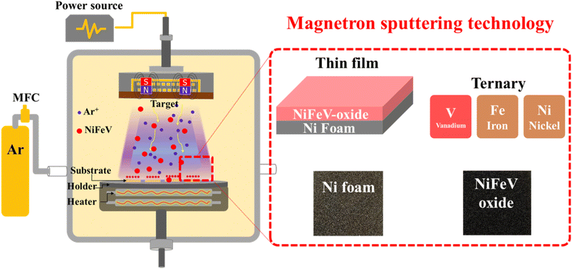
For the deposition procedure (Fig. 1), the sputtering chamber underwent a sequential evacuation sequence: initially, to achieve a low vacuum state through a rotary pump and subsequently, to attain a high vacuum state using a turbo molecular pump for 1 hour until a pressure of 10−6 torr was reached. After this, a pre-sputtering step ensued, employing a low power of 30 watts for approximately 30 minutes to remove surface contaminants. The target with a working distance of 4 cm underwent sputtering at a temperature of 200 °C, employing a power of 50 watts for 30 minutes. The entire sputtering process was enacted with argon gas as the operational gas at a pressure of 9.5 × 10⁻³ torr. Based on the specific sputtering targets employed, including Ni1Fe1V0.2, Ni1Fe1V0.5, Ni1Fe1V0.7, and Ni1Fe1V1, the resulting as-sputtered samples were denoted as NFV-0.2, NFV-0.5, NFV-0.7, and NFV-1.0, respectively. A binary NiFe catalyst was also synthesized using the same methodology, omitting vanadium in the mixture for comparative purposes.2.3. Characterization
The crystal structures of the as-prepared NiFeV-oxide thin films were examined using a Bruker D2 Phaser X-ray diffractometer using Cu-Kα radiation (35 kV, 20 mA, λ = 1.5184 Å). The morphology was studied using a high-resolution field-emission scanning electron microscope (SEM, JEOL JMS-6500F) at an accelerating voltage of 15 kV. Transmission electron microscopy (TEM) and energy dispersive X-ray spectroscopy (EDS) were conducted using an FEI Talos F200X at an operating voltage of 200 kV. An X-ray photoelectron spectrometer (XPS, VG Scientific ESCALAB 250) was used to determine each element's surface chemical oxidation states. Electron Paramagnetic Resonance (EPR) spectra were recorded on a Bruker EPR-plus spectrometer. Raman spectra were recorded using a HORIBA (LabRAM HR evolution) at an excitation wavelength of 532 nm.2.4. Electrochemical measurements
All electrochemical measurements were conducted using a BioLogic SP-300 potentiostat. For investigating the HER and OER, we employed a three-electrode system comprising the following components: the as-prepared NiFeV-oxide (1 × 1 cm2) as the working electrode, platinum foil as the counter electrode, and a Hg/HgO electrode as the reference electrode. Considering consistency, all reported potentials were accordingly adjusted to the Reversible Hydrogen Electrode (RHE) using the Nernst equation.19 We conducted Linear Sweep Voltammetry (LSV) experiments to assess the OER and HER performance. For the OER, the potential window ranged from 1.2 to 1.7 V vs. RHE, while for the HER, it spanned from 0 to −0.55 V vs. RHE. These experiments were carried out in a 1.0 M KOH electrolyte solution. We conducted Electrochemical Impedance Spectroscopy (EIS) across a frequency range from 100 mHz to 200 kHz to study the electron transfer behavior. During OER studies, a positive potential of 1.325 V vs. RHE was applied, while a negative potential of −0.275 V vs. RHE was utilized for HER studies. Furthermore, we estimated the electrochemical double-layer capacitance (Cdl) by performing cyclic voltammetry (CV) measurements at varying scan rates, ranging from 20 to 100 mV. To investigate the overall water splitting, we employed a two-electrode cell. The optimal NFV-07 catalyst served as both the cathode and anode simultaneously. Moreover, Pt/C and RuO2 inks were drop-cast onto Ni foam substrates, creating Pt/C and RuO2 electrodes for comparison.To delve into the site reconstruction phenomenon of NiFeV-oxide during the OER, we conducted operando Raman analysis using a confocal Raman spectrometer (HORIBA, LabRAM HR evolution) with an excitation wavelength of 532 nm. We employed a home-built three-electrode electrochemical cell for the electrochemical tests. In this setup, the as-prepared NFV-0.7 sample was utilized as the working electrode (1 × 1 cm2), accompanied by a platinum foil functioning as the counter electrode and a Hg/HgO reference electrode. External bias to the working electrode during the Raman analysis was applied with the same potentiostat (BioLogic, SP-300). The potential-dependent Raman spectroscopy was executed under open-circuit conditions or during potentiostatic electrolysis, employing chronoamperometry in a 1 M KOH electrolyte. Distinctly applied potentials ranging from 0.2–0.5 V vs. Hg/HgO were studied to explore the site reconstruction of NFV-0.7 during the oxidation process.
3. Results and discussion
3.1. Electrocatalyst characterization
The crystal characteristics of the as-sputtered NiFeV-oxide thin film were explored using X-ray diffraction. As depicted in Fig. S2,† the X-ray diffraction patterns of NiFe and NFV-0.7 exhibit no discernible peaks resembling the substrate spectrum. The XRD outcome strongly suggests that the as-sputtered binary NiFe and ternary NiFeV-oxide thin films have an amorphous character.16 The chemical composition and states of NFV-0.7 were assessed by utilizing X-ray Photoelectron Spectroscopy. In the high-resolution Ni spectrum presented in Fig. 2a, there are two main peaks for Ni 2p3/2 and Ni 2p1/2. These two peaks could be deconvoluted into four subpeaks assigned to the binding energy of Ni0 (852.5 and 870.2 eV) and Ni2+ (855.3 and 872.8 eV).18 Similarly, in the Fe 2p spectrum (Fig. 2b), the peaks located at 707.4, 709.5, and 712.1 eV, respectively, correspond to the 2p3/2 triplets of Fe0, Fe2+, and Fe3+,20 reflecting the high oxidation states of iron. In the V 2p spectrum (Fig. 2c), the deconvoluted peaks at 523.3, 516.1, and 514.8 eV distinctly correspond to the binding energies of V4+ (2p1/2), V4+ (2p3/2), and V0 (2p3/2),21 respectively, delineating the oxidation states of vanadium within the compound. Moreover, as shown in Fig. 2d, the O 1s spectrum can be deconvoluted into two peaks: OL and OV. The OL peak at 529.3 eV is assigned to the lattice oxygen in metal oxide, whereas the OV peak at 531 eV indicates the occurrence of oxygen vacancy from the defective oxide.22 Despite the evident presence of metallic signatures associated with nickel, iron, and vanadium, the manifestation of these metals in their higher oxidation states, such as Ni in the 2+ valence state, Fe in the 2+ and 3+ valence states, and V in the 4+ state, can be attributed to surface oxidation processes. For instance, in the case of metallic iron nanoparticles (NPs), a partial oxidation process occurs when the powder is exposed to air. This oxidation creates an oxide layer on the NP surface, effectively acting as a protective shield for the inner iron core from oxidation.23 In the previously reported Ni–Fe–V alloy system, there are five distinct single-phase regions:24 α-phase iron (α Fe), a combination of gamma-phase iron and nickel (γFe + Ni), sigma phase (σ), pure vanadium(V), and a potential Ni3V. The partial oxidation generates nonstoichiometric Fe3O4−x, characterized by varying levels of Fe2+ and Fe3+ states, and the emergent VO2−y compound related to the V4+ state. These phases form within the nickel matrix with oxygen deficiencies or vacancies, consistent with XPS data.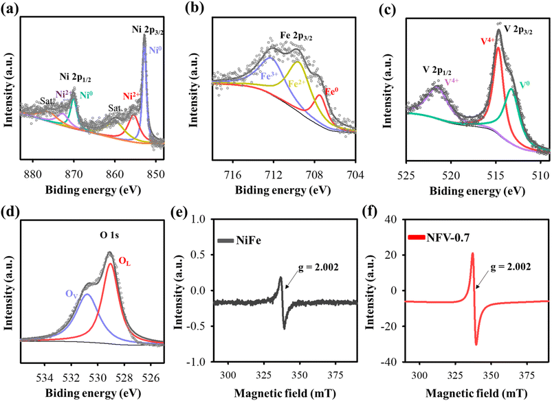 | ||
| Fig. 2 High-resolution XPS spectra of (a) Ni 2p, (b) Fe 2p, (c) V 2p, and (d) O 1s for NFV-0.7. EPR spectra of (e) NiFe and (f) NFV-0.7. | ||
To provide further evidence of the presence of oxygen vacancies, we conducted EPR analyses on NiFe and NFV-0.7. As depicted in Fig. 2e and f, both the as-sputtered catalysts displayed EPR signals at g = 2.002, which can be attributed to electrons trapped at oxygen vacancy sites.25 Moreover, it is noteworthy that the signal intensity of NFV-0.7 is notably stronger than that of NiFe, indicating a higher concentration of oxygen vacancies in NFV-0.7. This enhanced oxygen vacancy in the NFV-0.7 catalyst can be attributed to the synergistic effect of vanadium substitution into NiFe.
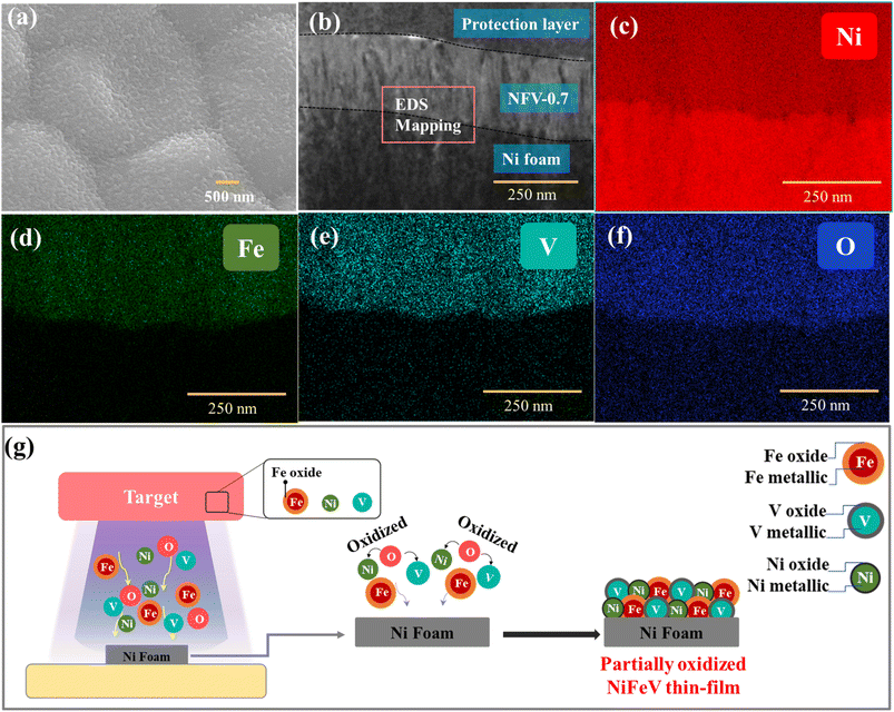
Further analyzing the top-view SEM image (Fig. 3a) and the cross-sectional TEM image (Fig. 3b), it becomes evident that the sputtered NFV-0.7 thin film exhibits a dense and uniform structure accompanied by a flat and smooth surface. The thickness of the catalyst film was approximately 250 nm. Moreover, the morphologies and solid structures of the NiFeV-oxide thin films remain unaffected by variations in element concentrations, as corroborated by the SEM images (Fig. S3†). Further validation of the chemical compositions of NFV-n (n = 0.2, 0.5, 0.7, and 1) was achieved through EDS measurements. As presented in Table S1,† the ratio of metals within the film slightly deviated from the intended design. In the NFV-0.2 catalyst, after the introduction of a small amount of V into the NiFe host, the actual ratio of Ni![[thin space (1/6-em)]](https://www.rsc.org/images/entities/char_2009.gif) :
:![[thin space (1/6-em)]](https://www.rsc.org/images/entities/char_2009.gif) Fe
Fe![[thin space (1/6-em)]](https://www.rsc.org/images/entities/char_2009.gif) :
:![[thin space (1/6-em)]](https://www.rsc.org/images/entities/char_2009.gif) V was measured at 1
V was measured at 1![[thin space (1/6-em)]](https://www.rsc.org/images/entities/char_2009.gif) :
:![[thin space (1/6-em)]](https://www.rsc.org/images/entities/char_2009.gif) 0.76
0.76![[thin space (1/6-em)]](https://www.rsc.org/images/entities/char_2009.gif) :
:![[thin space (1/6-em)]](https://www.rsc.org/images/entities/char_2009.gif) 0.11, showing a slight variance from the target ratio of 1
0.11, showing a slight variance from the target ratio of 1![[thin space (1/6-em)]](https://www.rsc.org/images/entities/char_2009.gif) :
:![[thin space (1/6-em)]](https://www.rsc.org/images/entities/char_2009.gif) 1
1![[thin space (1/6-em)]](https://www.rsc.org/images/entities/char_2009.gif) :
:![[thin space (1/6-em)]](https://www.rsc.org/images/entities/char_2009.gif) 0.2. For NFV-0.5, NFV-0.7, and NFV-1, the atomic percentage of V gradually increased from 10.2% to 15.6% and 22.6%, respectively accompanied by V ratios relative to Ni of 0.23, 0.31, and 0.56. It is worth noting that the lower V ratio relative to the intended design is attributed to its lower sputtering yield compared to Ni.26 Furthermore, the elemental mapping images in Fig. 3c–f exhibit a uniform dispersion of Ni, Fe, V, and O elements throughout the NFV-0.7 thin film. This homogeneous distribution ensures an even allocation of catalytic active sites across the NFV-0.7 surface.
0.2. For NFV-0.5, NFV-0.7, and NFV-1, the atomic percentage of V gradually increased from 10.2% to 15.6% and 22.6%, respectively accompanied by V ratios relative to Ni of 0.23, 0.31, and 0.56. It is worth noting that the lower V ratio relative to the intended design is attributed to its lower sputtering yield compared to Ni.26 Furthermore, the elemental mapping images in Fig. 3c–f exhibit a uniform dispersion of Ni, Fe, V, and O elements throughout the NFV-0.7 thin film. This homogeneous distribution ensures an even allocation of catalytic active sites across the NFV-0.7 surface.
The formation of our partially oxidized NiFeV thin film is depicted in Fig. 3g. During the magnetron sputtering, high-energy argon ions (Ar+) are directed toward the NiFeV target surface. When these ions collide with target materials, they transfer their kinetic energy to the target atoms and molecules. As a result of this high-energy bombardment, the O atoms present in the target gain sufficient kinetic energy to overcome the binding forces that hold them in the oxide lattice.27 Consequently, these oxygen species escape from the NiFeV target. The O atoms ejected from the target surface are highly energetic, which can lead to their further oxidation of other metal elements. Moreover, with a limited supply of oxygen, partial oxidation occurs, creating nonstoichiometric oxides, such as Fe3O4−x and VO2−y, and introducing oxide defects, i.e., oxygen vacancies, as revealed by XPS and EPR results. This process underscores the intricate chemistry involved in thin film fabrication and highlights the potential for further exploration through adjustments in target composition or plasma environment. It showcases the capability of developing advanced materials with tailored properties to suit specific applications.
3.2. Electrocatalytic performance
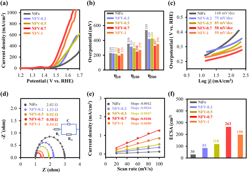
The assessment of kinetic behavior for the as-synthesized electrodes was evaluated by calculating the Tafel slope from the LSV data, presented in Fig. 4c. The corresponding Tafel analysis reveals a significant decrease in Tafel values for NFV-n compared to NiFe upon the vanadium substitution. Particularly notable is NFV-0.7, displaying the most substantial reduction from 148 to 58 mV dec−1. The lower Tafel slope underscores the essential role of vanadium substitution in NiFe, leading to a marked enhancement in OER kinetics.
Electrochemical impedance spectroscopy was employed to gain deeper insights into the charge transfer of the NiFeV-oxide electrode concerning the OER. The experimental data were fitted using an equivalent circuit model (inset in Fig. 4d). Analyzing the Nyquist plot in Fig. 4d, the electrochemical charge transfer resistance (Rct) for NFV-0.7 was determined to be 0.38 Ω. This value is notably smaller compared to its NFV-n counterparts—NiFe (2.02 Ω), NFV-0.2 (1.23 Ω), NFV-0.5 (0.92 Ω), and NFV-1 (0.54 Ω). The impedance finding suggests a more efficient charge transport mechanism for NFV-0.7 in enhancing OER activity.
To elucidate the robust electrochemical activity of NiFeV-oxide, double-layer capacitance (Cdl) was examined to quantify the electrochemical active surface area (ECSA). This evaluation was executed using cyclic voltammetry, as illustrated in Fig. S5.† Notably, NFV-0.7 displayed the largest ECSA of 10.6 μF cm−2 or 263 cm2 among the samples (Fig. 4e and f). This value represents an 8.77-fold greater ECSA than the 1.2 μF cm−2 or 30 cm2 of the binary NiFe catalyst. This substantial enhancement implies a higher amount of exposed active sites on the surface of NFV-0.7, thereby significantly contributing to its intrinsically high activity.
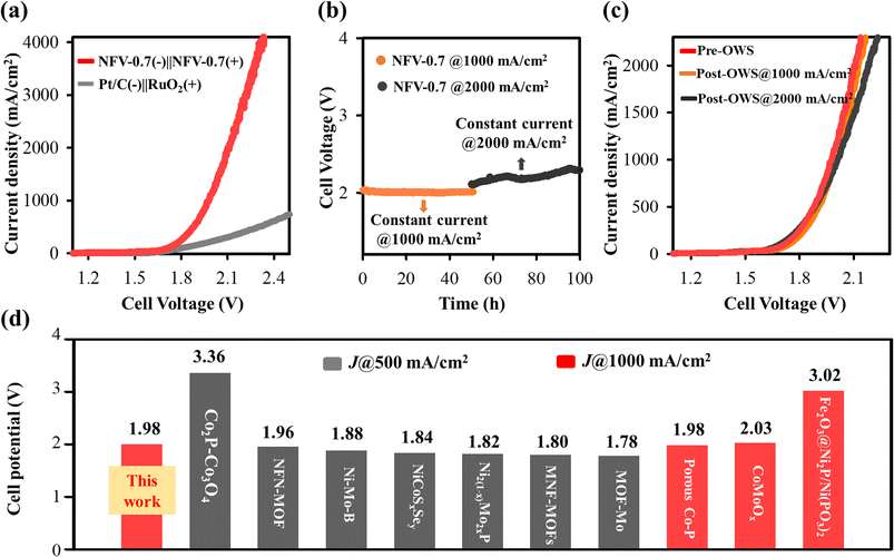
To ensure the applicability of our thin film bifunctional NFV-0.7 catalyst, we conducted investigations under industrially relevant current densities. It is observed that water splitting operated at higher current densities needs shallow cell potentials of 1.88 V, 1.98 V, and 2.12 V to achieve current densities of 500, 1000, and 2000 mA cm−2, respectively. Our OWS performance notably surpasses that of the Pt/C(−)‖RuO2(+)-coupled electrolyzer.
The enduring electrochemical stability of NFV-0.7 was assessed for a 100 hour operational period at 1000 mA cm−2, followed by 2000 mA cm−2. As shown in Fig. 6b, the NFV-0.7 catalyst consistently maintained its potential during the stability test at 1000 mA cm−2. However, a slight increase in potential was observed when the constant current was elevated to 2000 mA cm−2. It is worth noting that during the OWS, many bubbles formed, and a considerable amount of liquid electrolyte was consumed, resulting in reduced electrode-to-electrolyte contact. This change in contact may be responsible for the slight potential shift observed in the stability test at 2000 mA cm−2. Additionally, as illustrated in Fig. 6c, the recorded LSV curves indicate minimal degradation in the OWS activity of NFV-0.7 before and after the stability tests, underscoring the remarkable stability of the NFV-0.7 catalyst.
The results presented above clearly showcase the excellent electrocatalytic prowess of NiFeV-oxide in both the OER and HER. The exceptional performance of NiFeV-oxide thin film catalysts can be predominantly attributed to the synergistic effects arising from nickel, iron, and vanadium alloying and reaction. Introducing vanadium into NiFe expedites the formation of oxidation phases, such as Fe3O4−x and VO2−y, within the nickel matrix, especially with oxygen deficiencies or vacancies. The partially oxidized or nonstoichiometric oxides optimize the binding energy of water and its intermediates with the electrocatalyst, thereby enhancing the intrinsic catalytic performance of the OER and HER. Moreover, the inclusion of vanadium also plays a pivotal role in augmenting the electrical conductivity and surface area of NiFeV-oxide. This augmentation creates a practical pathway for charge transfer and increases the availability of active sites, further bolstering the catalytic activity of the system. A comparative plot with the reported cell voltages at high current densities of 500 and 100 mA cm−2 is shown in Fig. 6d. It is worth mentioning that there are limited reports on the development of efficient bifunctional catalysts for overall water splitting operated at 1000 mA cm−2. Remarkably, the performance of our NFV-0.7 catalyst surpasses that of most high-performance electrocatalysts e.g., Co2P–Co3O4,28 NFN-MOF,29 Ni–Mo–N HF,30 NiCoSxSey/NCF,31 N2(1−x)Mo2xP,32 MNF-MOFs,33 MOF-MoSAWSA,34 porous Co–P,35 CoMoOx,36 and Fe2O3@Ni2P/Ni(PO3)2.37
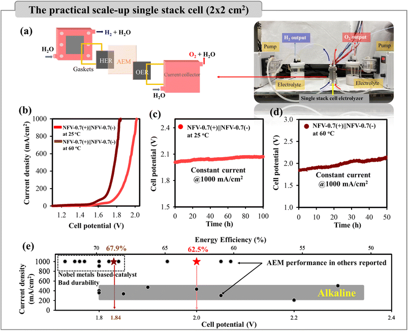 | ||
| Fig. 7 (a) A schematic plot of the 4 cm2 NFV-0.7(−)‖NFV-0.7(+) electrolyzer for overall water splitting. (b) LSV curves for water splitting using NFV-0.7 as both the cathode and anode at different temperatures. (c) The stability test at 1000 mA cm−2 or 4000 mA in 1 M KOH for 100 h at 25 °C and (d) for 50 h at 60 °C. (e) The water splitting performance of the NFV-0.7(−)‖NFV-0.7(+) single-stack cell, in terms of the functions of cell potential, current density, and energy efficiency. The gray-shaded box indicates the operating parameters for industrial alkaline electrolysis, while black symbols represent AEM performance from the literature (based on Table S4†). | ||
As presented in Fig. 7b, the NFV-0.7(−)‖NFV-0.7(+) stack cell exhibited exceptional performance, achieving industrial current densities of 500 and 1000 mA cm−2 at corresponding cell potentials of 1.95 and 2.00 V at 25 °C without cell heating. It is worth noting that the presence of the alkaline membrane introduced only a marginal increase in cell potential when compared to water splitting in a membrane-free single cell with 1.88 V @ 500 mA cm−2 and 1.98 V @ 1000 mA cm−2. Furthermore, no notable increase in cell voltage was observed over a continuous 100 hour operation at consistent current densities of 4000 mA or 1000 mA cm−2 (Fig. 7c). The remarkable consistency was evident in the nearly overlapping LSV curves before and after the stability operation, further underscoring the sustained electrolytic performance (Fig. S6a†).
To better emulate industrial operating conditions, our NFV-0.7(−)‖NFV-0.7(+) electrolyzer was operated at 60 °C. This higher temperature significantly reduced cell potential, requiring 1.84 V at 1000 mA cm−2 due to enhanced electrode reactions. Furthermore, as illustrated in Fig. 7d, the stability test conducted at 1000 mA cm−2 and 60 °C for 50 h revealed no noticeable increase in voltage, indicating the robust durability of NFV-0.7. This durability was further confirmed by the results of the LSV tests performed both before and after the stability test (Fig. S6a†).
The hydrogen and oxygen production rates were experimentally ascertained under a constant current density of 1000 mA cm−2vs. reaction time, as illustrated in Fig. S6b.† The yield was 427.5 mL h−1 cm−2 for hydrogen and 213.9 mL h−1 cm−2 for oxygen, aligning closely with the theoretically anticipated 2![[thin space (1/6-em)]](https://www.rsc.org/images/entities/char_2009.gif) :
:![[thin space (1/6-em)]](https://www.rsc.org/images/entities/char_2009.gif) 1 ratio. The faradaic efficiencies for the HER and OER were quantified by comparing them with the theoretical gas evolution to elucidate the electrochemical performance further. Remarkably, these efficiencies approached 100%, signifying the elevated selectivity of the thin film bifunctional catalyst towards the HER/OER. Impressively, our calculations revealed an energy efficiency of ∼62.5% for the single stack cell designed for water electrolysis without the cell heating and reaching ∼67.9% at 60 °C (refer to the detailed computation provided in the ESI†). Based on these findings, the NFV-0.7 thin film catalyst holds substantial promise as an efficient bifunctional electrode for practical industrial-scale water-splitting applications.
1 ratio. The faradaic efficiencies for the HER and OER were quantified by comparing them with the theoretical gas evolution to elucidate the electrochemical performance further. Remarkably, these efficiencies approached 100%, signifying the elevated selectivity of the thin film bifunctional catalyst towards the HER/OER. Impressively, our calculations revealed an energy efficiency of ∼62.5% for the single stack cell designed for water electrolysis without the cell heating and reaching ∼67.9% at 60 °C (refer to the detailed computation provided in the ESI†). Based on these findings, the NFV-0.7 thin film catalyst holds substantial promise as an efficient bifunctional electrode for practical industrial-scale water-splitting applications.
Fig. 7e presents a comprehensive comparison of specific characteristics, encompassing the operating current density, cell voltage, and energy efficiency, between our alkaline exchange membrane (AEM) water electrolyzer constructed with bifunctional NFV-0.7 electrodes and commercial, industrial alkaline water electrolysis (AWE). To deliver typical operating current densities of 200–500 mA cm−2 for a traditional alkaline water electrolyzer, the commercial cells required ∼1.8–2.4 V, equating to a cell energy efficiency of 50–70%.38,39 However, the challenge of scaling up to higher current densities in industrial applications is further complicated by factors like the delamination of binder-coated catalysts under elevated current densities, higher temperatures, e.g., 60 °C, and increased operation pressure.
As previously mentioned, our water electrolyzer showcases an exceptional performance, requiring cell potentials of 1.84 V at 1000 mA cm−2, resulting in a remarkable cell energy efficiency of 67.9% at 60 °C. The industrial AWE has not yet achieved operation at 1000 mA cm−2. Moreover, the performance of our electrolyzer surpasses the majority of previously reported electrolyzers (indicated by back symbols in Fig. 7e and Table S4 in the ESI†). While the NFV-0.7 single-stack cell showed promising performance, as compared to noble-metal-based AEM electrolyzers, it is essential to recognize that binder-pasted RuO2-, IrO2- or Pt/C electrocatalysts suffer a risk of catalyst detachment if the electrode intends to operate above 500 mA cm−2 for a more extended operation period.
3.3. Post-characterization
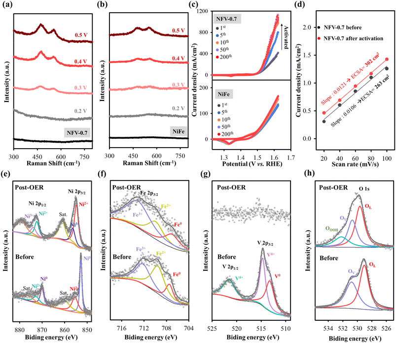
The NFV-0.7 catalyst was further characterized by SEM, operando Raman, and XPS after being used for OWS processes to elucidate alterations in composition and structure. Upon comparing the post-electrocatalysis morphology of NFV-0.7 with the initial morphology (Fig. S7†), it becomes evident that there is no discernible change in the morphology of NFV-0.7 after the HER process. Conversely, NFV-0.7 has a noteworthy phase transformation after utilizing the OER to form a nanosheet structure. This observation signifies a surface compositional transformation attributable to anodization in an alkaline solution during the OER process. It has been reported that the NiFe-based electrocatalyst is sensitive to potential changes and can undergo self-reconstruction during the OER process.20 To investigate the active intermediate species during this oxidation process, we conducted potential-dependent operando Raman spectroscopy, ranging from 0.2 to 0.5 V versus Hg/HgO, on our NFV-0.7 and NiFe samples. The Raman spectra revealed that at the open-circuit potential, there was no signal detected (Fig. 8a and b). This observation aligns with the amorphous nature of the NFV-0.7 and NiFe catalysts, as evidenced by X-ray diffraction results. In the case of NFV-0.7, no phase transformation was observed when a slightly positive potential of 0.2 V vs. Hg/HgO was applied. However, as the applied potential reached 0.3 V, broad bands centered around 554 cm−1 and 471 cm−1 appeared. These bands indicate the conversion of surface oxides into (oxy)hydroxides, i.e., γ-Ni(Fe)OOH.40 As the potential was further increased from 0.3 to 0.5 V vs. Hg/HgO, an intensification of these two bands is observed, suggesting that surface transformation became more pronounced at higher applied potentials. A similar phenomenon has been observed with the NiFe catalyst; however, the signal of the reconstruction species is only clearly observed when the applied potential reaches 0.5 V vs. Hg/HgO. This suggests that introducing vanadium into NiFe to create a high concentration of oxygen vacancies plays an essential role in the self-reconstruction process of NFV-0.7.To gain a deeper insight into the evolution of the electrochemical properties occurring in the film during the self-reconstruction process, cyclic voltammetry (CV) sweeps were conducted on NiFe and NFV-0.7 for 200 OER cycles. As shown in Fig. 8c, NiFe initially demonstrates a modest current density in the first CV cycle (115 mA cm−2 @ 1.6 V vs. RHE), which gradually improves in subsequent cycles and maintains a current density of 148 mA cm−2 @ 1.6 V by the 200th cycle. In contrast, NFV-0.7 undergoes an activation process, resulting in a significant increase in current density at 1.6 V vs. RHE, starting from 315 mA cm−2 in the first cycle and reaching 854 mA cm−2 in the 50th cycle. Subsequently, the current stabilizes, achieving 886 mA cm−2 by the 200th cycle. Moreover, based on the double-layer capacitances obtained from the CV tests of NFV-0.7 before and after activation, as shown in Fig. 8d and S8,† the ECSA reveals a 1.15-fold increase after 200 OER cycles. This indicates that the activation process leads to the restructuring of NFV-0.7, significantly enhancing the exposed surface area and improving OER performance.
XPS measurements were further conducted to investigate the surface states of NFV-0.7 after electrocatalytic reactions. Post the OER test, the presence of Ni0 became notably absent (Fig. 8e). Additionally, the relative increase in the Ni2+ signal within the total peak and the emergence of a Ni3+ peak at a binding energy of 873.9 eV (2p1/2) and 856.0 eV (2p3/2) signify the oxidation of Ni to a higher valence state. This observation aligns with in situ Raman spectroscopy findings. Simultaneously, the Fe 2p region (as depicted in Fig. 8f) reveals that the fitted peaks of Fe 2p at 705, 709.7, and 712.6 eV correspond to Fe0, Fe2+, and Fe3+, respectively. These peaks exhibit slight changes after the OER process, with a more substantial presence of Fe3+, indicating partial surface transformations. In the O 1s high-resolution spectrum of NFV-0.7 post-OER (Fig. 8h), the emergence of an (oxy)hydroxyl-like peak (OOOH) at a higher binding energy of approximately 532.2 eV is attributed to the self-reconstruction species, i.e., Ni(Fe)OOH.41–43 Additionally, there is a decrease in the relative percentage of oxygen vacancies, which declines from 45.5% to 30.9% for NFV-0.7 post-OER. It is indicated that the oxygen vacancies in NFV-0.7 become occupied by OH ions, forming bonds with Ni/Fe sites to generate active Ni/Fe–OOH* intermediate species during the OER process.44 Notably, as depicted in Fig. 8g, the signal from V 2p exhibits a significant reduction in the post-OER sample, implying the absence of V element on the surface. Metal leaching has been identified as a crucial factor closely linked to the reconstruction process, affecting the local electronic structure of oxides and impeding further restructuring.45 In another study,46 it was demonstrated that the leaching of metal cations in NiFe-LDH nanosheets led to cationic vacancy defects. Furthermore, with increased applied potential, these as-formed cationic vacancy defects (VM) tend to adopt the VMOH configuration, ultimately transforming into VMOH–H as the most active state. These cationic defects effectively lower the energy barrier for the electro-oxidative surface restructuring of NiFe-LDH during oxidation, thereby enhancing OER electrocatalysis. Hence, as evidenced by operando Raman and cyclic voltammetry tests, our findings suggest that the dissolution of vanadium and the presence of a large number of oxygen vacancies are the principal factors regulating the activation and surface restructuring processes of the NiFeV-oxide pre-catalyst during OER electrocatalysis.
As depicted in Fig. S9,† the XPS analysis demonstrates that the high-resolution XPS peaks of V 3d, Ni 2p, Fe 2p, and O 1s closely resemble those observed in NFV-0.7 before the HER test. However, the initial ratio of OV/OL for NFV-0.7 was about 0.84, and the ratio slightly decreased to 0.65 after the HER process. Moreover, it is noted that there is an increase in the intensity of the Ni2+ peak along with the appearance of a small species of oxygen in a hydroxyl-like peak (at the binding energy of 532.8 eV) after the HER. This change is attributed to the side effect of the electrode immersing in an alkaline solution for 100 hours. Prolonged exposure to such conditions accelerates surface oxidation, increasing the likelihood of forming Ni species in a higher oxidation state.
3.4. Electrocatalytic mechanism
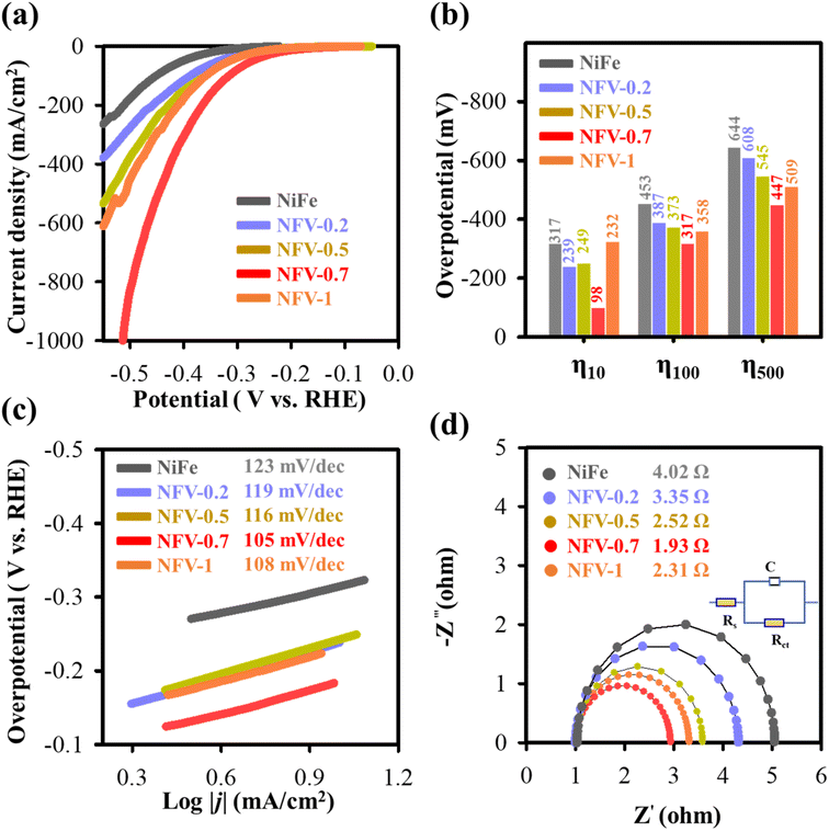
The kinetic mechanism for the enhanced HER performance has to be related to the accelerated water dissociation, as evidenced by the Volmer step observed in NFV-0.7 after vanadium substitution. The notable reduction in Tafel value, decreasing from 123 mV dec−1 (for NiFe) to 105 mV dec−1, indicates that water activation occurs more readily on NFV-0.7.47 The surface oxidation process during the sputter deposition leads to the formation of nonstoichiometric Fe3O4−x and VO2−y oxide compounds within the nickel matrix. As schematically explained in Fig. 9a, these compounds possess oxygen vacancies that attract the negatively charged oxygen in H2O, thus weakening the O–H bonds.48 Simultaneously, the nonstoichiometric oxides preferentially adsorb H*, optimizing the energy associated with H adsorption/desorption, which promotes the Heyrovsky step in the HER mechanism. Furthermore, substituting vanadium into the NiFe system results in a significantly larger ECSA than NiFe. This higher ECSA value provides more available surface-active sites for the Heyrovsky step, leading to faster HER kinetics.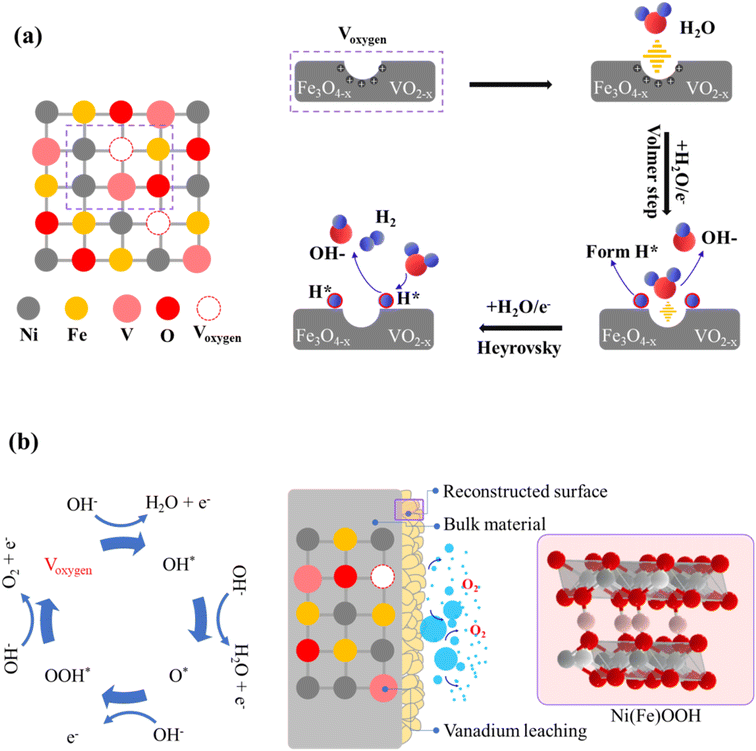 | ||
| Fig. 9 Schematic representations of (a) the HER and (b) OER reaction mechanisms proceeding on the surface of NFV-0.7. | ||
Regarding the post-OER XPS findings, oxygen defects also significantly impact the oxidation of Ni and Fe sites. Previous research indicates that a high concentration of oxygen vacancies (Voxygen), especially on the surface, allows for structural flexibility in oxide materials.49,50 Moreover, substituting V into the NiFe system is crucial in creating surface Voxygen.51 The accumulation of Voxygen on the oxide surface facilitates the H2O-involving oxidation and then induces surface reconstruction, transforming into oxyhydroxides (as illustrated in Fig. 9b).52 Additionally, electron interactions between Ni and V during the OER self-reconstruction process further promote the formation of the higher valence state of Ni3+ in NFV-0.7. It has been reported that Ni and Fe sites exhibit a strong attraction for O 2p electrons, making the deprotonation reaction of medium OH– i.e., Ni(Fe)–OH* relatively facile.53 Consequently, due to the enhanced electrophilicity of the exposed Ni and Fe sites, Voxygen likely facilitates the adsorption of OH ions on active Ni and Fe sites to form the adsorbed Ni(Fe)–OH* species and to promote the deprotonation process at lower potentials (e.g., 1.225 V, as exhibits in operando Raman spectroscopy). Those oxygen vacancy-involving reactions lead to active oxygen species (Ni(Fe)–OOH*) forming on the surface, contributing to enhanced OER activity.45 A point to mention is the notable V leaching from the surface after the OER, as evidenced by the V 2p XPS. The leaching of vanadium also plays a critical role in the phase transformation and activation process, resulting in the exposure of a larger active surface area, significantly enhancing OER activity.54
4. Conclusions
A magnetron sputtering technique has been successfully used to develop a partially oxidized NiFeV thin film. Our NiFeV-oxide, i.e., NFV-0.7 catalyst, demonstrates remarkable electrocatalytic prowess, particularly at elevated current densities. Substituting vanadium within a nickel–iron oxide matrix creates atomic-level active sites and the oxide defect, optimizing the interaction between catalyst and water molecules. This enhancement boosts the electrocatalytic reaction kinetics and results in exceptional performance with very low overpotentials of 410 mV for the OER and −512 mV for the HER at a current density of 1000 mA cm−2. The overall water-splitting OWS performance of the NFV-0.7 catalysts demonstrates a low cell voltage of 1.88 V @ 500 mA cm−2 and 1.98 V @ 1000 mA cm−2. Notably, our catalysts exhibit no electrochemical degradation during stability tests at 1000 mA cm−2, a significant challenge in this field. Our NFV-0.7(−)‖NFV-0.7(+) single stack cell water electrolyzer, operating at 60 °C, achieves a high current density of 1000 mA cm−2 at a cell potential of 1.84 V. The stack cell performed at 1000 mA cm−2 or 4000 mA for 50 h without degradation. The hydrogen production rate was experimentally determined at 1000 mA cm−2, yielding a hydrogen yield rate of 427.5 mL h−1 cm−2 with approximately 100% faradaic efficiency. The designed electrolyzer achieved a high energy efficiency of 67.9%. Notably, operando Raman spectroscopy reveals the site reconstruction of NFV-0.7 during anodic oxidation, ultimately transforming into a stable NiFe(oxy)hydroxyl. This transformation generates more active sites on the surface, contributing to enhanced OER activity. This study presents a straightforward approach to designing a non-noble metal-based, durable, self-supported, and highly efficient bifunctional electrocatalyst capable of operating at high current densities for overall water-splitting.Author contributions
Quoc-Nam Ha: supervision; methodology; investigation; visualization; writing – original draft. Chen-Hao Yeh: formal analysis; investigation. Noto Susanto Gultom: supervision; investigation. Dong-Hau Kuo: conceptualization; funding acquisition; writing – review & editing.Conflicts of interest
The authors declare that they have no known competing financial interests or personal relationships that could have appeared to influence the work reported in this paper.Acknowledgements
This work was supported by the National Science and Technology Council (NCST), Taiwan, under grant numbers MOST-110-2221-E-011-038-MY3, MOST 110-2221-E-011-100-MY3, and MOST-110-2811-E-011-507. Thanks to the Precious Instrumentation Center at NTUST for ULVAC PHI 5000 VersaProbe III XPS analysis.References
- S. S. Kumar and H. Lim, Energy Rep., 2022, 8, 13793–13813 CrossRef.
- S. S. Kumar and V. Himabindu, Mater. Sci. Energy Technol., 2019, 2, 442–454 Search PubMed.
- J. Liang, Z. Li, X. He, Y. Luo, D. Zheng, Y. Wang, T. Li, B. Ying, S. Sun and Z. Cai, Mater. Today, 2023, 69, 193–235 CrossRef CAS.
- H. A. Miller, K. Bouzek, J. Hnat, S. Loos, C. I. Bernäcker, T. Weißgärber, L. Röntzsch and J. Meier-Haack, Sustainable Energy Fuels, 2020, 4, 2114–2133 RSC.
- S. Grigoriev, V. Fateev, D. Bessarabov and P. Millet, Int. J. Hydrogen Energy, 2020, 45, 26036–26058 CrossRef CAS.
- Y. Chen, J. Yu, J. Jia, F. Liu, Y. Zhang, G. Xiong, R. Zhang, R. Yang, D. Sun and H. Liu, Appl. Catal., B, 2020, 272, 118956 CrossRef CAS.
- S. Meyer, A. V. Nikiforov, I. M. Petrushina, K. Köhler, E. Christensen, J. O. Jensen and N. J. Bjerrum, Int. J. Hydrogen Energy, 2015, 40, 2905–2911 CrossRef CAS.
- D. Wang, X. Zhang, D. Zhang, Y. Shen and Z. Wu, Appl. Catal., A, 2016, 511, 11–15 CrossRef CAS.
- Q.-N. Ha, N. S. Gultom, M. Z. Silitonga, T. N. Gemeda and D.-H. Kuo, Chem. Eng. J., 2023, 467, 143253 CrossRef CAS.
- Q.-N. Ha, N. S. Gultom, C.-H. Yeh and D.-H. Kuo, Chem. Eng. J., 2023, 472, 144931 CrossRef CAS.
- W. Zhu, W. Chen, H. Yu, Y. Zeng, F. Ming, H. Liang and Z. Wang, Appl. Catal., B, 2020, 278, 119326 CrossRef CAS.
- J. Chen, L. Zhang, J. Li, X. He, Y. Zheng, S. Sun, X. Fang, D. Zheng, Y. Luo and Y. Wang, J. Mater. Chem. A, 2023, 11, 1116–1122 RSC.
- Y. Wang, G. Qian, Q. Xu, H. Zhang, F. Shen, L. Luo and S. Yin, Appl. Catal., B, 2021, 286, 119881 CrossRef CAS.
- L. Zhang, Z. Shi, Y. Lin, F. Chong and Y. Qi, Front. Chem., 2022, 10, 866415 CrossRef CAS PubMed.
- Y. Li, X. Du, J. Huang, C. Wu, Y. Sun, G. Zou, C. Yang and J. Xiong, Small, 2019, 15, 1901980 CrossRef PubMed.
- N. S. Gultom, T.-S. Chen, M. Z. Silitonga and D.-H. Kuo, Appl. Catal., B, 2023, 322, 122103 CrossRef CAS.
- Z. Qi, Y. Zeng, Z. Hou, W. Zhu, B. Wei, Y. Yang, B. Lin and H. Liang, Nano Res., 2023, 16, 4803–4811 CrossRef CAS.
- J. Sun, B. Yu, F. Tan, W. Yang, G. Cheng and Z. Zhang, Int. J. Hydrogen Energy, 2022, 47, 15764–15774 CrossRef CAS.
- R. A. Nickell, W. H. Zhu, R. U. Payne, D. R. Cahela and B. J. Tatarchuk, J. Power Sources, 2006, 161, 1217–1224 CrossRef CAS.
- M. W. Louie and A. T. Bell, J. Am. Chem. Soc., 2013, 135, 12329–12337 CrossRef CAS PubMed.
- E. Hryha, E. Rutqvist and L. Nyborg, Surf. Interface Anal., 2012, 44, 1022–1025 CrossRef CAS.
- H. Tian, X. Cui, L. Zeng, L. Su, Y. Song and J. Shi, J. Mater. Chem. A, 2019, 7, 6285–6293 RSC.
- H. Li, J. Wan, Y. Ma and Y. Wang, Chem. Eng. J., 2016, 301, 315–324 CrossRef CAS.
- C. Zhao, S. Yang, Y. Lu, Y. Guo, C. Wang and X. Liu, Calphad, 2014, 46, 80–86 CrossRef CAS.
- R.-A. Eichel, Phys. Chem. Chem. Phys., 2011, 13, 368–384 RSC.
- K. Wasa, Handbook of Sputtering Technology, 2012, pp. 41–75 Search PubMed.
- H. D. Smyth, Rev. Mod. Phys., 1945, 17, 351 CrossRef CAS.
- X. Yu, M. Wang, X. Gong, Z. Guo, Z. Wang and S. Jiao, Adv. Energy Mater., 2018, 8, 1802445 CrossRef.
- D. Senthil Raja, X. F. Chuah and S. Y. Lu, Adv. Energy Mater., 2018, 8, 1801065 CrossRef.
- H. Liu, X. Li, L. Chen, X. Zhu, P. Dong, M. O. L. Chee, M. Ye, Y. Guo and J. Shen, Adv. Funct. Mater., 2022, 32, 2107308 CrossRef CAS.
- S. Ma, J. Huang, C. Zhang, G. Chen, W. Chen, T. Shao, T. Li, X. Zhang, T. Gong and K. K. Ostrikov, Chem. Eng. J., 2022, 435, 134859 CrossRef CAS.
- L. Yu, I. K. Mishra, Y. Xie, H. Zhou, J. Sun, J. Zhou, Y. Ni, D. Luo, F. Yu and Y. Yu, Nano Energy, 2018, 53, 492–500 CrossRef CAS.
- D. S. Raja, H.-W. Lin and S.-Y. Lu, Nano Energy, 2019, 57, 1–13 CrossRef.
- C.-C. Cheng, T.-Y. Lin, Y.-C. Ting, S.-H. Lin, Y. Choi and S.-Y. Lu, Nano Energy, 2023, 112, 108450 CrossRef CAS.
- Y. Li, B. Wei, Z. Yu, O. Bondarchuk, A. Araujo, I. Amorim, N. Zhang, J. Xu, I. C. Neves and L. Liu, ACS Sustain. Chem. Eng., 2020, 8, 10193–10200 CrossRef CAS.
- B. Ren, D. Li, Q. Jin, H. Cui and C. Wang, ChemElectroChem, 2019, 6, 413–420 CrossRef CAS.
- X. Cheng, Z. Pan, C. Lei, Y. Jin, B. Yang, Z. Li, X. Zhang, L. Lei, C. Yuan and Y. Hou, J. Mater. Chem. A, 2019, 7, 965–971 RSC.
- A. Buttler and H. Spliethoff, Renewable Sustainable Energy Rev., 2018, 82, 2440–2454 CrossRef CAS.
- I. Vincent and D. Bessarabov, Renewable Sustainable Energy Rev., 2018, 81, 1690–1704 CrossRef CAS.
- K. Yue, J. Liu, Y. Zhu, C. Xia, P. Wang, J. Zhang, Y. Kong, X. Wang, Y. Yan and B. Y. Xia, Energy Environ. Sci., 2021, 14, 6546–6553 RSC.
- M. Fingerle, S. Tengeler, W. Calvet, T. Mayer and W. Jaegermann, J. Electrochem. Soc., 2018, 165, H3148 CrossRef CAS.
- A. Liu, G. Liu, H. Zhu, B. Shin, E. Fortunato, R. Martins and F. Shan, Appl. Phys. Lett., 2016, 108, 233506 CrossRef.
- H. Zhang, X. He, K. Dong, Y. Yao, S. Sun, M. Zhang, M. Yue, C. Yang, D. Zheng and Q. Liu, Mater. Today Phys., 2023, 38, 101249 CrossRef CAS.
- Z. Xiao, Y.-C. Huang, C.-L. Dong, C. Xie, Z. Liu, S. Du, W. Chen, D. Yan, L. Tao and Z. Shu, J. Am. Chem. Soc., 2020, 142, 12087–12095 CrossRef CAS PubMed.
- H. B. Tao, L. Fang, J. Chen, H. B. Yang, J. Gao, J. Miao, S. Chen and B. Liu, J. Am. Chem. Soc., 2016, 138, 9978–9985 CrossRef CAS PubMed.
- Y. j. Wu, J. Yang, T. x. Tu, W. q. Li, P. f. Zhang, Y. Zhou, J. f. Li, J. t. Li and S. G. Sun, Angew. Chem., Int. Ed., 2021, 60, 26829–26836 CrossRef CAS PubMed.
- H. Yan, Y. Xie, A. Wu, Z. Cai, L. Wang, C. Tian, X. Zhang and H. Fu, Adv. Mater., 2019, 31, 1901174 CrossRef PubMed.
- E. Sadeghi, S. Chamani, E. Erdem, N. S. Peighambardoust and U. Aydemir, ACS Appl. Energy Mater., 2023, 6, 7658–7671 CrossRef CAS.
- Z. Xiao, Y. Wang, Y.-C. Huang, Z. Wei, C.-L. Dong, J. Ma, S. Shen, Y. Li and S. Wang, Energy Environ. Sci., 2017, 10, 2563–2569 RSC.
- Z. Li, Y. Zhang, Y. Feng, C. Q. Cheng, K. W. Qiu, C. K. Dong, H. Liu and X. W. Du, Adv. Funct. Mater., 2019, 29, 1903444 CrossRef.
- W. Wan, H. Wu, Z. Wang, G. Cai, D. Li, H. Zhong, T. Jiang, C. Jiang and F. Ren, Appl. Surf. Sci., 2023, 611, 155732 CrossRef CAS.
- K. Zhu, F. Shi, X. Zhu and W. Yang, Nano Energy, 2020, 73, 104761 CrossRef CAS.
- Z. Cai, L. Li, Y. Zhang, Z. Yang, J. Yang, Y. Guo and L. Guo, Angew. Chem., 2019, 131, 4233–4238 CrossRef.
- T. Wu, S. Sun, J. Song, S. Xi, Y. Du, B. Chen, W. A. Sasangka, H. Liao, C. L. Gan and G. G. Scherer, Nat. Catal., 2019, 2, 763–772 CrossRef CAS.
Footnote |
| † Electronic supplementary information (ESI) available. See DOI: https://doi.org/10.1039/d3ta05699f |
| This journal is © The Royal Society of Chemistry 2024 |

