 Open Access Article
Creative Commons Attribution 3.0 Unported Licence
A new layered barium cobaltite electrode for protonic ceramic cells†
Allan J. M.
Araújo
 *ab,
Vanessa C. D.
Graça
 ab,
Rafael A.
Raimundo
c,
Antonio C. L.
Filho
 d,
Daniel A.
Macedo
d and
Francisco J. A.
Loureiro
 *ab
*ab
aTEMA – Centre for Mechanical Technology and Automation, Department of Mechanical Engineering, University of Aveiro, 3810-193 Aveiro, Portugal. E-mail: allan@ua.pt; allanjmaraujo@gmail.com; francisco.loureiro@ua.pt
bLASI – Intelligent Systems Associate Laboratory, Guimarães, Portugal
cDepartment of Theoretical and Experimental Physics, UFRN – Federal University of Rio Grande do Norte, 59078-970 Natal, Brazil
dMaterials Science and Engineering Postgraduate Program – PPCEM, Federal University of Paraíba – UFPB, 58051-900 João Pessoa, Brazil
First published on 4th December 2023
Abstract
Protonic ceramic cells (PCCs) hold significant promise as energy conversion devices operating at lower temperatures in comparison to traditional Solid Oxide Cells (SOCs). However, the widespread adoption of PCCs depends on developing innovative, high-performing, electrode materials that exhibit enhanced chemical compatibility with barium-based perovskite electrolytes. Here, a new cobaltite, Ba2Co9O14 (BCO), is employed for the first time as an electrocatalyst for oxygen reactions in PCCs in contact with a BaZr0.852Y0.148O3−δ (BZY15) + 4 mol% ZnO (sintering agent) electrolyte. BCO displays electrochemical performance comparable to the current state-of-the-art oxygen electrode under wet conditions (pH2O ∼ 10−2 atm). Furthermore, it demonstrates excellent chemical compatibility with the BZY15 electrolyte. Thermogravimetric experiments reveal no significant oxygen loss below 800 °C and no noticeable proton uptake. Conversely, X-ray photoelectron spectroscopy results highlight the formation of surface oxygen vacancies and mixed valent Co3+/Co2+ states, as corroborated by bond valence sum calculations from Rietveld refinement of the X-ray diffraction data. Consequently, due to the platelet-like morphology of the BCO electrode grains, and considering its poor bulk ionic conduction, the surface diffusion process becomes highly important in explaining the high-performing electrochemical behaviour. Moreover, the impedance spectroscopy data analysis brings to light the existence of electronic leakage within the electrolyte substrate, leading to a significant underestimation of the electrode polarisation resistance and misconception of the electrode mechanism. To address this issue, a data correction is applied, revealing that electrode kinetics is strongly rate-limited by oxygen diffusion on the surface of the BCO grains towards the triple-phase boundary, where proton transfer occurs, releasing water. In contrast, the adsorption and/or the oxygen dissociation steps are facilitated given the predominantly electronic character of the BCO material, which is suggested to originate from a small polaron hopping mechanism. Our results, thereby, introduce a new intergrowth series of cobaltites, which present an exciting avenue for exploration in the context of PCCs.
1 Introduction
With the aim of increasing the longevity of ceramic fuel cells, simplifying auxiliary systems, and enhancing the overall affordability of solid oxide cell (SOC) technology, researchers have developed protonic ceramic cells (PCCs) designed to operate at lower temperatures (e.g., below 700 °C).1 Similarly to the SOCs, the kinetics of the oxygen electrode is critical for the overall electrochemical performance of the cell.2 Oxygen-electrode materials have been actively explored and optimised, with notable advancements achieved through oxygen-ion conducting electrolytes.3–5 However, despite demonstrating favourable performance in SOCs, some materials cannot be directly employed in the protonic counterpart systems. This problem is mainly attributed to their chemical incompatibility with state-of-the-art barium-zirconate/cerate-based proton-conducting electrolytes,6–10 which has led to the investigation of new compositions as a point of interest for PCCs.11,12 Furthermore, an additional challenge associated with SOC oxygen electrode materials, when employed in PCCs, is their insufficient activity in water splitting/formation or their instability under high steam conditions.Barium-containing compositions are interesting cathode options due to their high basicity, as discussed for doped lanthanum nickelates.13 In this respect, Tarutin et al.14 studied Ba-doped Pr2NiO4+δ electrodes, indicating the Pr1.8Ba0.2NiO4+δ composition as the optimised sample when considering the transport and electrochemical properties. Notably, they observed a polarisation resistance (Rpol) of ∼2 Ω cm2 at 600 °C (pH2O = 0.03 atm in air) using impedance spectroscopy in a symmetrical cell configuration (BaCe0.5Zr0.3Y0.1Yb0.1O3−δ electrolyte). In a recent work by some current authors, the double perovskite Ba2NiMoO6−δ was proposed for application in PCCs.15Rpol of ∼4 Ω cm2 was obtained at 800 °C in wet oxygen (pH2O ∼10−2 atm), using a BaCe0.7Zr0.1Y0.2O3−δ electrolyte. The electrode material BaGd0.8La0.2Co2O6−δ on BaZr0.7Ce0.2Y0.1O3−δ, studied by Strandbakke et al.,16 exhibited a Rpol of ∼0.15 Ω cm2 at 600 °C, when exposed to a wet oxygen atmosphere (pH2O ∼0.03 atm). BaCo0.4Fe0.4Zr0.2O3−δ was investigated by Shang et al.17 on the BaCe0.7Zr0.1Y0.1Yb0.1O3−δ electrolyte. At 600 °C, the Rpol was ∼1 Ω cm2 in air (pH2O = 0.03 atm in air). Zou et al.18 reported the BaCe0.16Y0.04Fe0.8O3−δ electrode on the BaCe0.7Zr0.1Y0.1Yb0.1O3−δ electrolyte, demonstrating a Rpol value of 0.27 Ω cm2 at 600 °C in a 5 vol%-air atmosphere. In another work, an excellent polarisation resistance of ∼0.09 Ω cm2 (at 600 °C) was obtained for the Ba0.5Sr0.5(Co0.7Fe0.3)0.6875W0.3125O3−δ electrode on the BaCe0.7Zr0.1Y0.1Yb0.1O3−δ electrolyte by Hu et al.19 (3 vol% water-containing air). Because of this stronger basic character and better chemical compatibility, other materials with barium in the structure are of interest for developing oxygen electrodes with higher electrochemical performance. On the other hand, the basicity of barium-based oxides typically results in poor stability under water vapour-containing atmospheres,20 thus, creating additional challenges on the choice of the electrode composition, where a compromise between basicity and chemical stability needs to be achieved.
A new family of layered barium cobaltites emerges as a promising choice for use in PCCs. The Ban+1ConO3n+3(Co8O8) family exhibits a structural arrangement characterised by CdI2-type and perovskite layers.21 Single crystals corresponding to n = 1 (Ba2Co9O14) and n = 2 (Ba3Co10O17) have been prepared,21–23 but only Ba2Co9O14 (BCO) synthesised in pure phase. BCO can be employed to mitigate undesirable cation diffusion and minimise the concentration disparity of the alkaline-earth element within the electrolyte. This compound demonstrates rhombohedral symmetry under typical ambient conditions.23 In terms of electrical properties, Delorme et al.24 reported positive values for the Seebeck coefficient, indicating a p-type conduction mechanism. Additionally, they measured an electrical conductivity of approximately 200 S cm−1 at a temperature of 600 °C.
Despite its good electrical properties, to our knowledge, no reports currently exist on using the BCO material as an oxygen electrode for PCCs. An investigation is conducted to correlate the crystal structure, thermal behaviour, cobalt oxidation state, surface oxygen-ion vacancy concentration, and electrochemical properties of the BCO phase system under humidified atmospheres (pH2O = 10−2 atm). The electrode mechanism is underscored using a symmetric cell configuration on BaZr0.852Y0.148O3−δ (BZY15) electrolyte substrates, with minor additions of 4 mol% ZnO (as a sintering agent). Nevertheless, an essential consideration in our work concerns the presence of significant electronic leakage current in typical proton-conducting perovskite electrolytes.25 When analysing a PCC electrode under oxidising conditions, accounting for this aspect is indispensable. Specifically, BZY15 + 4 mol% ZnO demonstrates significant p-type electronic conductivity.26 This implies the parallel transport of protons and oxygen-ions (ionic current), accompanied by the simultaneous (parallel) transfer of electronic holes (electronic current), through the electrolyte substrate. In addition, these currents can also be extended through the electrode in the case of bulk triple-conducting compounds. Conversely, in the case of pure electronic-conducting electrodes, these ionic currents should be confined to the triple phase boundaries.16 This critical factor, which substantially underestimates the magnitude of the polarisation resistance,27 remains relatively underexplored in the existing literature on electrodes for PCCs. Therefore, an approach is implemented to allow for a correct mechanistic interpretation of the electrochemical behaviour of the Ba2Co9O14 electrode under varying oxygen partial pressures.
2 Experimental
2.1 Powder synthesis and chemical compatibility
The Ba2Co9O14 (BCO) powder was synthesised by the solid-state reaction route.24 Co3O4 (Chem-Labs, 99+%) and BaCO3 (Merck, ≥99%) were used as precursor materials during the high-energy milling process (400 rpm), followed by calcination in air at 900 °C for 8 h (5 °C min−1) to ensure the stability limit.21,24 BaZr0.852Y0.148O3−δ (BZY15), synthesised as described below, was used as an electrolyte substrate.The BZY15 powder was prepared by high-energy milling of stoichiometric amounts of precursor mixtures of barium peroxide (BaO2, Riedel-de-Häen, 95%) with 8YSZ ((ZrO2)0.92(Y2O3)0.08 = Zr0.852Y0.148O1.926, Tosoh Co.). Seven milling cycles were executed under ambient conditions at a rotational speed of 650 rpm for 2 h per cycle.28 This was achieved using tetragonal zirconia vials (from Retsch), along with zirconia balls (Tosoh Co.). To prevent excessive heating during milling, the process involved steps of 5 min of milling followed by an equal pause duration. Finally, the powder was compacted into a pellet to enhance the reaction, followed by a calcination process at 1200 °C for 10 h (3 °C min−1).
A 50![[thin space (1/6-em)]](https://www.rsc.org/images/entities/char_2009.gif) :
:![[thin space (1/6-em)]](https://www.rsc.org/images/entities/char_2009.gif) 50 wt% mixture of BCO with the electrolyte material (BZY15) underwent heat treatment at 900 °C for 24 h under ambient air conditions to assess the compatibility between the electrode and the electrolyte components. To improve the interphase connectivity and ensure the successful completion of the reactivity test, a pellet was fabricated using the powdered mixture. The temperature of 900 °C was based on the maximum temperature used in the sintering process.
50 wt% mixture of BCO with the electrolyte material (BZY15) underwent heat treatment at 900 °C for 24 h under ambient air conditions to assess the compatibility between the electrode and the electrolyte components. To improve the interphase connectivity and ensure the successful completion of the reactivity test, a pellet was fabricated using the powdered mixture. The temperature of 900 °C was based on the maximum temperature used in the sintering process.
2.2 Powder analysis
Powder X-ray diffraction (XRD) analysis was performed using a Rigaku SmartLab SE diffractometer with a Cu-Kα radiation source operating at 40 kV and 30 mA. XRD data were collected in the range 20° ≤ 2θ ≤ 80°, with a stepwidth of 0.02° and a scan speed of 3° min−1. Rietveld refinement was conducted with the SmartLab Studio II software package (Rigaku). A structural illustration for the BCO compound was drawn using VESTA software, with data obtained from Rietveld refinement.Thermal analysis of the BCO sample was also performed by thermogravimetry/differential thermal analysis (TGA/DSC; model STA449/6/G, Netzsch, Jupiter, Germany) up to 1000 °C in oxygen (O2) and nitrogen (N2).
The powder morphology was studied by scanning electron microscopy (SEM, TESCAN VEGA's 4th generation) integrated with energy-dispersive X-ray spectroscopy (EDS detector model Essence™) for analysing the elemental distribution.
X-ray photoelectron spectroscopy (XPS) measurements were acquired in an Ultra High Vacuum (UHV) system using a SPECS Phoibos 150 spectrometer equipped with a high-intensity monochromatic Al-Kα X-ray source (1486.6 eV). XPS measurements were carried out on the synthesised BCO powder. Charge correction was performed utilising the C 1s peak of adventitious carbon at 284.8 eV. Spectra were fitted using the XPSPeak fitting program, version 4.1.
2.3 Preparation and microstructural characterisation of the electrode–electrolyte symmetrical cell
Electrolyte substrates were prepared using the BZY15 powder, with densification of cylindrical pellets achieved through the incorporation of 4 mol% of ZnO (Merck) as a sintering aid, followed by sintering at 1300 °C for 5 h in a bed of the same BZY15 + 4 mol% ZnO powder, as studied by Soares et al.26 The BCO film was applied onto both sides of the pre-polished BZY15 + 4 mol% ZnO substrate using the screen printing technique, with a slurry prepared by mixing BCO powder with terpineol, ethyl cellulose, and stearic acid.29 Initially, the electrode film was applied to one side of the BZY15 + 4 mol% ZnO substrate. Subsequently, the second film was deposited concentrically on the opposite side, followed by a drying step at around 60 °C. Electrodes were then sintered in air at 900 °C.30,31The electrochemical cells comprised two symmetrical electrodes, as detailed in previous works.29,31 The symmetrical cells were fabricated using a BZY15 + 4 mol% ZnO substrate with ∼12 mm diameter and ∼1.6 mm thickness, with electrodes of ∼5 mm diameter on each side. Grazing incidence angle XRD was employed on the symmetrical cell to confirm its phase stability.
Cross-section analyses of the half-cell were performed with a Hitachi SU-70 equipment coupled with energy dispersive spectroscopy (EDS).
The thermal expansion coefficient (TEC) of the bar-shaped Ba2Co9O14 sample, sintered at 900 °C, was measured using a Linseis L75HS1600OE dilatometer. The measurement was carried out in air, with the temperature reaching a maximum of 800 °C.
2.4 Electrochemical characterisation
Electrochemical properties were investigated by Impedance Spectroscopy (IS) using an Electrochemie Autolab PGSTAT302N analyser. Current collectors on the electrodes were implemented using gold grids. The tests were performed between 700 °C and 500 °C, with a step of 50 °C, a signal amplitude of ±50 mV, and a frequency range of (10−2 to 106) Hz. In this work, BCO was investigated under oxidising conditions as a PCC oxygen electrode, in wet O2–N2 mixtures (pH2O ∼10−2 atm; pO2 = 1 atm to 10−2 atm, 50 mL min−1). Humidity was achieved by bubbling the gases through a KCl-saturated H2O solution at room temperature. The impedance data were fitted using equivalent circuits, enabling the extraction of resistances and capacitances associated with the electrochemical processes, where the resistance values were multiplied by the electrode area (0.1963 cm2) and then divided by 2, to account for the symmetrical cell configuration.3 Results and discussion
3.1 Powder morphology, thermal behaviour, and phase compatibility
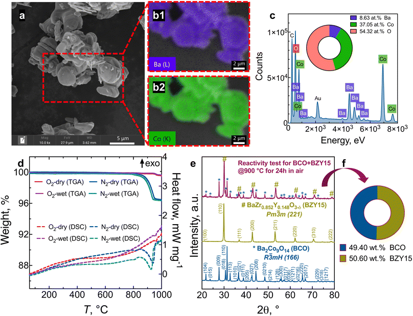
Fig. 1 presents the results of the powder analysis. The SEM image of the BCO powder, Fig. 1a, reveals a platelet-like morphology, with particle sizes ranging between approximately 1 μm and 4 μm. The energy-dispersive X-ray spectroscopy (EDS) mapping images demonstrate that both barium and cobalt are distributed homogeneously (Fig. 1b). Meanwhile, the EDS spectrum shown in Fig. 1c indicates that the stoichiometry of the synthesised BCO is close to the nominal composition of Ba2Co9O14.TG-DSC profiles are provided in Fig. 1d in oxygen and nitrogen atmospheres under dry and wet conditions. When a ceramic protonic conductor is exposed to water vapour, water is dissociatively incorporated into oxygen-ion vacancies  , previously generated by acceptor doping. One proton from the water molecule is attached to a regular lattice oxygen-ion, forming a protonic
  defect (a hydroxide ion on an oxygen-ion site), and the remaining hydroxide ion fills an oxygen vacancy, forming the second
  . This is an acid–base reaction with an equilibrium expression given by:32
 | (1) |
The maximum water uptake is dictated by the oxygen vacancy concentration. Nonetheless, no evident mass change could be observed in the TG profiles up to around 800 °C, regardless of the humidity conditions (dry or wet) in both atmospheres (O2 or N2), which points towards negligible proton uptake in BCO in such conditions.
Conversely, at high temperatures, a small mass change can be observed in both atmospheres, with the corresponding DSC curves exhibiting endothermic peaks starting at different temperatures for each atmosphere. In O2, this event starts at ∼950 °C and corresponds to a weight loss of ∼0.4% up to 1000 °C. Fig. S1† shows that the phase integrity was retained after exposure to dry and wet O2. Hence, it is likely that this weight loss is attributed to a small loss of oxygen, as previously reported in air at a lower temperature (∼900 °C to 915 °C).23,24
On the other hand, in the case of N2, a weight loss of ∼3.6% was observed between ∼800 °C and 1000 °C, accompanied by a sharp endothermic DSC peak. This phenomenon is attributed to the decomposition of Ba2Co9O14 into CoO, BaCoO2.23 and Ba1.09CoO3 (Fig. S1†), with some possible oxygen loss.23 Such decomposition process was previously observed in air by Ehora et al.,23 starting at ∼1030 °C, with a similar weight loss of around 3%.
Therefore, it is evident that the phase stability increases as the partial pressure of oxygen increases. In addition, a minimum oxygen partial pressure of ∼0.04 atm (O2–N2 mixture) was employed, which is two orders of magnitude higher than the pO2 of pure nitrogen (∼10−4 atm). With this in mind, the BCO electrode may favour the phase stability in electrolyser mode, particularly under elevated localised pO2 levels, in the conditions of water-vapour dissociation for electrolysis operation, where oxygen is formed. This factor aligns with the observed trend of increased chemical stability under more oxidising conditions in other cobaltites (e.g., Ca3Co4O9+δ).33
X-ray diffraction (XRD) patterns of BCO, BZY15, and the mixture BCO + BZY15 after treatment at 900 °C in air are depicted in Fig. 1e. There is no evidence of any chemical interreaction between BCO and BZY15 phases at the resolution of XRD. This observation remains true when the weight fraction closely approximates the nominal composition of 50![[thin space (1/6-em)]](https://www.rsc.org/images/entities/char_2009.gif) :
:![[thin space (1/6-em)]](https://www.rsc.org/images/entities/char_2009.gif) 50 (wt%), as illustrated in Fig. 1f.
50 (wt%), as illustrated in Fig. 1f.
3.2 Powder structural analysis and surface chemical behaviour
Fig. 2 shows the Rietveld refinement analysis for the room-temperature XRD pattern of the synthesized Ba2Co9O14 (BCO) powder. In Fig. 2a, the XRD pattern is represented by black circles, the Rietveld profile fitting is depicted by a continuous red line, the corresponding difference by a continuous green line, and the background by an orange line. In the present study, a pseudo-Voigt peak profile function was used for the profile fitting, and the background was fitted with a 5-coefficient polynomial function. The crystal structure of BCO, as depicted in Fig. 2b, is within the R![[3 with combining macron]](https://www.rsc.org/images/entities/char_0033_0304.gif) m space group, composed of an intergrowth of CoO2 brucite-like layers and Co3O12 octahedral trimers, interconnected by corner-sharing CoO4 tetrahedra.23,34 The lattice parameters of the synthesised samples are in the expected range for similar compositions,21,23,28 with a = b = 5.695(1) Å and c = 28.911(6) Å for Ba2Co9O14 (Rwp = 3.45%, Rp = 2.61%, χ2 = 1.83) and a = b = c = 4.2174(2) for BaZr0.852Y0.148O3−δ (Rwp = 5.28%, Rp = 4.02%, χ2 = 1.59).
m space group, composed of an intergrowth of CoO2 brucite-like layers and Co3O12 octahedral trimers, interconnected by corner-sharing CoO4 tetrahedra.23,34 The lattice parameters of the synthesised samples are in the expected range for similar compositions,21,23,28 with a = b = 5.695(1) Å and c = 28.911(6) Å for Ba2Co9O14 (Rwp = 3.45%, Rp = 2.61%, χ2 = 1.83) and a = b = c = 4.2174(2) for BaZr0.852Y0.148O3−δ (Rwp = 5.28%, Rp = 4.02%, χ2 = 1.59).
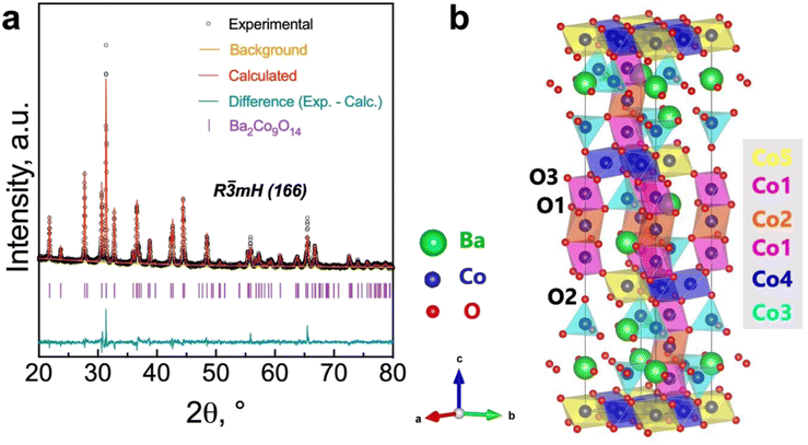 | ||
| Fig. 2 Rietveld refinement of the Ba2Co9O14 oxide: (a) room temperature XRD pattern; (b) crystal structure. | ||
The bond valence sum (BVS) calculation of the Co-ions that is presented in Table 1 indicates a mixed Co3+/Co2+ charge ordering at the different Co-site positions (Fig. 2b). The Co3+ ions adopting a low spin state occupy octahedral sites (Co1, Co2 and Co4), whereas Co2+ ions occupy both tetrahedral (Co3) and octahedral (Co5) sites. This configuration leads to a neutral Ba2Co32+Co63+O14 formula with a nominal oxidation state of +2.67 (that is close to the average oxidation state of +2.75 determined in this work, Table 1), in agreement with the data from Ehora et al. using neutron powder diffraction.23 This notable characteristic of the BCO material contrasts with that observed in other CdI2-containing Co-oxides, which present higher oxidation states, i.e., Co3+ and Co4+.21,23 In fact, when decreasing the oxidation state, the ionic radius of Co increases, which would, in principle, induce the formation of oxygen-ion vacancies to compensate for charge neutrality. This factor would also promote ionic conductivity and increase the electrocatalytic activity. Nonetheless, we should call attention to the non-evident changes in TG measurements up to around 800 °C (Fig. 1d), therefore excluding the possibility for significant oxygen-ion vacancy formation in the bulk below this temperature. In such a scenario, the electrocatalytic activity of BCO as an electrode material for operating at the intermediate temperature range (e.g., below 700 °C) may exclusively rely on its surface, as previously established for other cobaltite compounds with oxygen-ion diffusion limitations.35–38
| Bond def. | Co–O, Å | Wyckoff | BVS |
|---|---|---|---|
| Co1 (oct. LS Co 3+ ) | |||
| Co1–O1 (×3) | 1.9720(6) | 6c | 3.347 |
| Co1–O3 (×3) | 1.8673(1) | ||
![[thin space (1/6-em)]](https://www.rsc.org/images/entities/char_2009.gif) |
|||
| Co2 (oct. LS Co 3+ ) | |||
| Co2–O1 (×6) | 1.9856(5) | 3b | 2.773 |
![[thin space (1/6-em)]](https://www.rsc.org/images/entities/char_2009.gif) |
|||
| Co3 (tet. LS Co 2+ ) | |||
| Co3–O1 (×3) | 1.8927(3) | 6c | 2.342 |
| Co3–O2 | 1.9146(4) | ||
![[thin space (1/6-em)]](https://www.rsc.org/images/entities/char_2009.gif) |
|||
| Co4 (oct. LS Co 3+ ) | |||
| Co4–O2 (×2) | 1.9849(5) | 9e | 3.272 |
| Co3–O3 (×4) | 1.8723(2) | ||
![[thin space (1/6-em)]](https://www.rsc.org/images/entities/char_2009.gif) |
|||
| Co5 (oct. HS Co 2+ ) | |||
| Co5–O3 (×6) | 2.103(2) | 3a | 2.018 |
| Average BVS | 2.750 | ||
In line with the assumption that the surface characteristics of the BCO compound may have critical importance for the oxygen reduction/evolution electrode reactions, we performed X-ray photoelectron spectroscopy (XPS) measurements (Fig. 3 and Table 2), aiming to investigate the cobalt and oxygen surface properties. Fig. 3a depicts the high-resolution spectrum of the Co 2p3/2 region, which was fitted to accommodate two main components: Co3+ (779.619 eV) and Co2+ (781.135 eV), in agreement with previous works.40,41 The presence of a Co3+/Co2+ ratio higher than unity (1.842) at the surface is in line with the average BVS estimated from Rietveld refinement for the bulk (Table 1), in which a higher oxidation state of Co was also found.
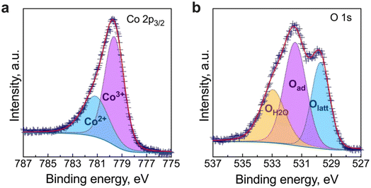 | ||
| Fig. 3 High-resolution X-ray photoelectron spectroscopy (XPS) spectrum obtained for (a) the Co 2p3/2 and (b) the O 1s regions. | ||
| Peak | Position, eV | Area | FWHM, eV | GL, % |
|---|---|---|---|---|
| Co 2p 3/2 | ||||
| Co3+ | 779.619 | 6967.998 | 1.853 | 15 |
| Co2+ | 781.135 | 3783.793 | 2.511 | 30 |
![[thin space (1/6-em)]](https://www.rsc.org/images/entities/char_2009.gif) |
||||
| O 1s | ||||
| Olatt | 529.728 | 1693.551 | 1.452 | 10 |
| Oad | 531.439 | 2478.049 | 1.773 | 10 |
| OH2O | 532.950 | 1559.063 | 1.980 | 30 |
Meanwhile, the high-resolution O 1s spectrum is shown in Fig. 3b. The lower binding energy peak (528.63 eV) is usually assigned to lattice oxygen (oxygen–metal bond, Olatt). In contrast, the middle peak (Oad) corresponds to the highly oxidative adsorbed oxygen species (O22− or O−). The peak at approximately 532.95 eV can be ascribed to unavoidable adsorbed water species due to interaction with the environment (OH2O).42,43 As previously reported,42,44 the concentration of surface oxygen vacancies can be estimated from the Oad/Olatt ratio, which, in our work, was determined to be 1.39. Previous studies have reported the benefits of increased catalytic activity due to the significant concentration of surface oxygen vacancies over that of the bulk.44–46 Therefore, the high concentration of surface-adsorbed oxygen species (i.e., [Oad] > [Olatt]) may have a potential impact on promoting the electrocatalytic activity on the BCO electrode.
3.3 Thermal expansion coefficient and cell microstructure
Previous to the study of the electrochemical behaviour of the symmetrical cells, the thermal expansion coefficient (TEC) of the BCO electrode and the microstructure of the fabricated symmetrical cell have been evaluated. As observed in Fig. 4, the TEC values demonstrate significant variations below ∼350 °C while reaching ∼23–24 × 10−6 °C−1 above this temperature. This range of TEC values is typical of other Co-based oxide systems.47,48 In our case, the change in thermal expansion behaviour is likely associated with a temperature-dependent spin state transition of Co3+ ions in the octahedral trimer (Co3O12), shifting from a low to a high spin state configuration.34,49 Consequently, the Co–O bond length expansion may explain the increase in TEC values. Note that this phenomenon is reversible when the temperature decreases.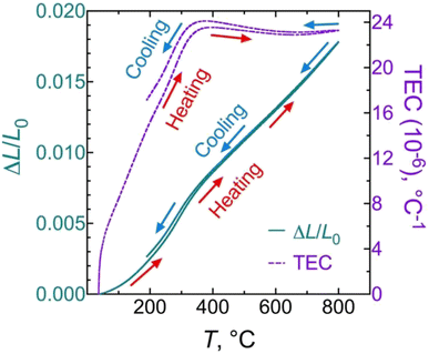 | ||
| Fig. 4 Linear thermal expansion/shrinkage (left) and thermal expansion coefficient (TEC) (right) of the Ba2Co9O14 ceramic. | ||
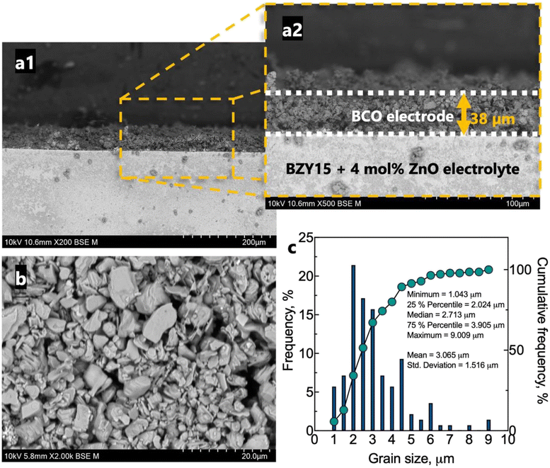
The microstructure of the half-cell is found in Fig. 5. The BZY15 + 4 mol% ZnO electrolyte support exhibits high density, whereas the BCO electrode layer displays porosity. This electrode microstructure is expected to have enhanced gas-phase diffusion of molecular oxygen. In addition, a uniform thickness of ∼38 μm was achieved. SEM was also performed on a top-view section to better visualise the grain size distribution. A statistical analysis of the grain size was also performed using a frequency distribution histogram with 140 measurements. The mean grain size measured approximately 3.1 μm ± 1.5 μm. The right-skewed distribution indicates that most data points occur around smaller sizes (D90 < 4.5 μm). However, there is a minority of grains with sizes significantly above the average, which leads to an extended tail on the right-hand side of the distribution. The inset compiles the values corresponding to 25%, 50% and 75% of the cumulative distributions. Another interesting point of the resultant microstructure is related to the platelet-like morphology of the BCO compound. This feature has been reported to be beneficial for the electrode polarisation processes, due to the large surface area available for oxygen reaction.29,35,37
3.4 Impedance spectroscopy equivalent circuit model (EQM) analysis
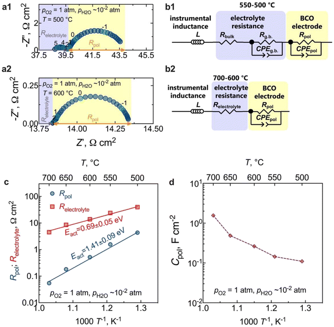
The results of electrochemical impedance spectroscopy (EIS) and the corresponding equivalent circuits used for fitting are presented in Fig. 6. Fig. 6a presents typical impedance spectra acquired at 500 °C and 600 °C in a wet O2 environment. The instrumental inductance (L) was omitted to provide a clearer visualisation of the electrode arc (but the original impedance data is in Fig. S2†). At lower temperatures (500 °C, Fig. 6a1), the resistive component along the real axis (Z′), devoid of any capacitive nature, is attributed to the electrolyte bulk resistance. A minor contribution at middle frequencies represents the electrolyte grain boundary process (capacitance ∼10−8 F cm−2),50,51 which can be described by both a resistive (Rg.b.) and a capacitive constant phase element (CPEg.b.) components. In this regard, note that the Rg.b. ‖CPEg.b. process is only partially resolved due to the large inductive contribution (Fig. S2†). Hence, we will only discuss the total electrolyte resistance (Relectrolyte = Rbulk + Rg.b.) in this work. From 600 °C (Fig. 6a2) onwards, the grain boundary process is no longer observed, and the high-frequency electrode intercept represents the total electrolyte resistance (Relectrolyte). The arc observed in the low-frequency region in both cases is, therefore, related to the electrode response, being also represented by a resistance (Rpol) and a constant phase element (CPEpol) that together describe the total electrode polarisation process (Rpol‖CPEpol).Equivalent circuit models (EQMs) incorporating these elements were used to fit the EIS data (Fig. 6b), being used to adequately describe the oxygen reduction reaction (ORR) mechanisms that can occur at the electrode. Fig. S3† depicts the residual plots resulting from fitting the impedance data using the EQMs from Fig. 6b. These plots illustrate the computed differences between the real and imaginary values of the data and the corresponding fitting, plotted as a function of measured frequency. The figures clearly demonstrate that both equivalent circuits yielded a minimal error, specifically less than 0.3%. This low error rate indicates the high-quality nature of the fitting process – an outcome of utmost importance as it underlines the reliability of the electrochemical parameters extracted from the fitting.
As observed in Fig. 6a, the electrode contribution occurs at very low frequencies, in a region typical of the following electrode processes: adsorption, dissociation, or the surface diffusion of intermediate oxygen species.52 Moreover, in contrast to what has been previously observed in the SOC literature, where one or more processes at high frequencies are typically attributed to interfacial charge-transfer phenomena,50–53 such processes are not observed in our current study. This behaviour is likely a consequence of the fast transfer of protons at the electrode/electrolyte interface and electrons at the current collector/electrode interface.33,54 In this regard, the coexistence of the observed mixed valence Co3+/Co2+ states in the BCO compound could be the origin of the electronic conductivity resulting from small polaron hopping,23 in the studied temperature range. Likewise, the absence of a gas-phase diffusion contribution supports our previous assumptions that the obtained electrode microstructure would offer sufficient porosity to facilitate the diffusion of molecular oxygen.
The temperature dependence of the polarisation and the ohmic resistances in oxygen is illustrated in Fig. 6c. The calculated electrode polarisation resistance, Rpol, of 0.5 Ω cm2 at 600 °C is very competitive with other PCC oxygen electrodes.14,16,50,55–58 However, a direct estimation of this value requires attention, given the electronic transport number of the electrolyte substrate. We will delve deeper into this aspect in the upcoming section.
To gain insight into the behaviour of the BCO electrode, the capacitance normalised by the electrode area is shown in Fig. 6d as a function of the temperature. We can observe that the capacitance values decrease with decreasing temperature, falling within the range of 0.1 F cm−2 and 1.6 F cm−2. This range is notably higher than the pure double-layer capacitance values, around (10−6 to 10−4) F cm−2,59 reinforcing that Rpol‖CPEpol is not primarily governed by interfacial charge transfer processes. Therefore, additional works were carried out as a function of oxygen partial pressure (pO2) to offer deeper insights into the electrode kinetics.
3.5 Oxygen partial pressure (pO2) dependence: short-circuiting correction
EIS measurements as a function of the oxygen partial pressure (pO2) within the range (10−2 to 1) atm were also performed, as presented in Fig. 7. The spectra (Fig. 7a) reveal an increase in magnitude with decreasing oxygen partial pressure. As observed in Fig. 7b, the Relectrolyte exhibits a dependency on pO2, with m = 0.11 ± 0.01, which concurs with the presence of significant electronic conductivity through the BZY15 + 4 mol% ZnO electrolyte.26 Depending on the temperature and the partial pressures of oxygen (pO2) and water vapour (pH2O), water can be dissociatively incorporated into oxygen-ion vacancies in the electrolyte, resulting in the creation of protonic defects at lower temperatures, as described in eqn (1). Nevertheless, in oxidising conditions and higher temperatures, they can also be occupied by oxygen, thereby promoting the formation of electronic holes (h˙), which may be localised on the oxygen-ions, creating hole polarons.60–62 This is a redox reaction with an equilibrium expression given by: | (2) |
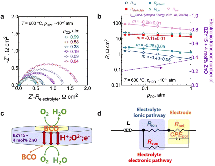 | ||
| Fig. 7 Electrochemical measurements at different oxygen partial pressures at 600 °C: (a) impedance spectra as a function of pO2 at 600 °C (please note that the high-frequency responses associated with ohmic resistances and inductive responses have been removed for the sake of clarity); (b) electrolyte (total, ionic, and electronic) and electrode polarisation resistances, along with the electronic transport number for BZY15 + 4 mol% ZnO obtained from ref. 26 (for the Rion, the line represents an average value); (c) schematic illustration of the electronic short-circuit across the BZY15 + 4 mol% ZnO membrane (highlighting the diffusion of both ionic (oxygen-ions and protons) and the electronic (holes) charge carriers through the electrolyte); (d) equivalent circuit including a parallel resistor for the compensation of the electronic short-circuiting. | ||
Keeping this consideration in view, in the case of a mixed ionic electronic conductor such as the BZY15 + 4 mol% ZnO substrate, direct calculation of Rpol is precluded due to the influence of an internal short-circuiting through the substrate (Fig. 7c). As detailed by Strandbakke et al.,16 in measurements conducted under high oxidising conditions, currents from various charge carriers run simultaneously, resulting in an overall polarisation that reflects a parallel connection of these currents (ionic and electronic). Therefore, to accommodate such a phenomenon, a parallel resistor can be incorporated (Fig. 7d) in order to model the electronic leakage (Reon).27,63
In this scenario, the electrolyte total electrical resistance presented in Fig. 6b corresponds to the parallel combination of the ionic (Rion) and electronic (Reon) resistances, given by:
 | (3) |
Conversely, the low-frequency intercepts of the EIS spectra (Fig. 7a) represent the total resistance (Rtotal) of the cell, which can be expressed as follows:
 | (4) |
Using this method, we can then determine the corrected total polarisation resistance of the electrode (Rpol,corr) using the following equation:
 | (5) |
 | (6) |
Fig. 7b compares the data of the total polarisation resistance as a function of oxygen partial pressure, with and without correction. The uncorrected pO2 dependency of m = −0.40 ± 0.05 has been reported to be due to limitations related to either (i) oxygen adsorption/desorption processes:16,64
| O2(g) ⇌ O2(ad) | (7) |
| O2(ad) + 2e− ⇌ O2(ad)2− | (8) |
| O2(ad)2− ⇌ 2Oad− | (9) |
| Oad− + e− ⇌ Oad2− | (10) |
On the other hand, a significant disparity is evident between corrected and uncorrected polarisation resistances, resulting in a change in the dependence on the oxygen partial pressure to m = 0.26 ± 0.05 (Fig. 7b). The corrected pO2 dependence is now close to that reported by Uchida et al.65 (i.e., m = −0.25) on platinum electrodes (a material that can also be considered a predominant bulk electronic conductor). Comparably to their work, the Rpol‖CPEpol process observed in the BCO electrode must be linked to the diffusion of adsorbed (and possibly charged) oxygen species, arising from the fast oxygen dissociation over the large area provided by the BCO platelets (Fig. 5), according to,
| O2(g) + 2e(BCO)− ⇌ 2Oad− | (11) |
| 2H(electrolyte)+ ⇌ 2H(TPB)+ | (12) |
| 2H(TPB)+ + Oad2− ⇌ H2O(TPB) | (13) |
| H2O(TPB) ⇌ H2O(g) | (14) |
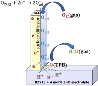
Overall, the electrode mechanism may involve surface diffusion of dissociated oxygen along with proton and charge transfer at the TPBs, leading to steam release. The overall electrode reaction can be described by:
| ½O2(g) + 2H(electrolyte)+ + 2e(BCO)− ⇌ H2O(g) | (15) |
To try to compile the above information, a tentative global electrode mechanism of the Ba2Co9O14 cathode is schematically illustrated in Fig. 8.
3.6 Structural and microstructural-chemical analysis after electrochemical tests
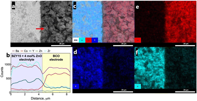
To assess any possible interreaction at the electrode/electrolyte interface, which could have had a critical impact on the electrochemical performance, energy-dispersive spectroscopy (EDS) analysis was further employed (Fig. 9a). The line scan profiles (Fig. 9b) indicate that there was no element diffusion between the electrode and electrolyte during the entire sintering process and throughout the electrochemical measurements as a function of temperature and oxygen partial pressure. The total duration of the cell test was approximately 80 h. This observation is paramount in preserving each component's electrochemical stability. Such a finding holds great promise, particularly considering that cobalt diffusion is a commonly reported issue.68,69 EDS mapping (Fig. 9c–f) of representative elements (Co, Zr, Y) for each component further validates this discussion, indicating that they are homogeneously distributed in the area of each component.Grazing incidence angle XRD was also employed on the tested symmetrical cell to investigate the presence of secondary phases related to the chemical compatibility of BCO and BZY15 + 4 mol% ZnO (Fig. 10). The diffraction peaks revealed the presence of only BZY15 + 4 mol% ZnO and BCO patterns. These results further confirm that no chemical interreaction occurred at the electrode–electrolyte interface during measurements.
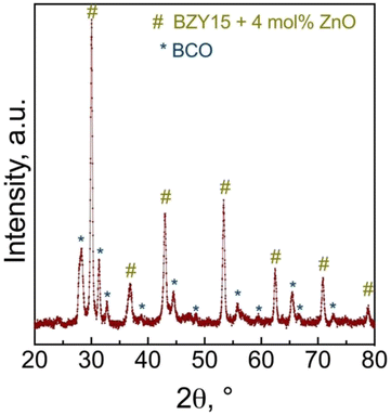 | ||
| Fig. 10 Grazing incidence X-ray diffraction (GIXRD) analysis of the BCO film deposited on the BZY15 + 4 mol% ZnO substrate after electrochemical measurements. | ||
4 Conclusions
It is demonstrated that Ba2Co9O14 (BCO) is chemically compatible with BZY15, possessing high electrochemical performance, with the overall polarisation resistance in line with values reported for the most advanced electrodes known to date. These findings pave the way for a series of new studies on this composition to be used for PCC applications in the intermediate temperature range, i.e., below 700 °C.The non significant changes in mass during thermogravimetric experiments below ∼800 °C suggest that the formation of bulk oxygen vacancies and, consequently, proton uptake is negligible at intermediate temperatures, even in humidified conditions (pH2O = 10−2 atm). Conversely, X-ray photoelectron spectroscopy (XPS) measurements indicate the formation of surface oxygen-ion vacancies and a high concentration of adsorbed oxygen species, which may be able to participate in the electrode process. Moreover, the coexistence of a mixed Co3+/Co2+ state in cobalt, determined by both XPS measurements as well as bond valence calculations from Rietveld refinement, highlight a possible small polaron hopping mechanism that is responsible for the predominant electronic behaviour of the BCO compound. Therefore, the electrode mechanism points to rate-limiting diffusion of adsorbed oxygen species toward the triple phase boundary, where proton transfer from the electrolyte occurs, releasing water. This factor concurs with the platelet-like structure of the BCO electrode, which provides a large surface area available for fast oxygen dissociation, but slow diffusion.
This work also emphasises the importance of careful consideration in electrochemical analysis since electronic transport in proton-conducting electrolytes can dramatically lower the apparent polarisation resistance values within the symmetrical experimental configuration. This effect can completely obscure the electrode's behaviour when measuring it as a function of oxygen partial pressure. To accurately determine the total polarisation resistance, it is essential to incorporate an external resistor into the equivalent circuit to include the electronic pathway. We, therefore, provide a rational basis for acquiring quantitative electrode polarisation data concerning PCC electrodes. This methodology can be subsequently employed by other researchers striving to elucidate electrode kinetics.
Conflicts of interest
There are no conflicts to declare.Acknowledgements
The authors acknowledge the following grants/projects: CEECIND/02797/2020, PTDC/CTM-CTM/2156/2020, https://doi.org/10.54499/2022.02498.PTDC, UIDB/00481/2020 and UIDP/00481/2020 from Fundação para a Ciência e a Tecnologia (FCT), and CENTRO-01-0145-FEDER-022083 from Centro Portugal Regional Operational Programme (Centro2020), under the PORTUGAL 2020 Partnership Agreement, through the European Regional Development Fund (ERDF). Rafael A. Raimundo and Daniel A. Macedo also acknowledge the Conselho Nacional de Desenvolvimento Científico e Tecnológico (CNPq/Brazil, 309430/2019-4 and 151879/2022-2). This study was also financed in part by the Coordenação de Aperfeiçoamento de Pessoal de Nível Superior – Brasil (CAPES) – Finance Code 001.References
- C. Duan, R. J. Kee, H. Zhu, C. Karakaya, Y. Chen, S. Ricote, A. Jarry, E. J. Crumlin, D. Hook, R. Braun, N. P. Sullivan and R. O'Hayre, Nature, 2018, 557, 217–222 CrossRef CAS PubMed.
- A. Lashtabeg and S. J. Skinner, J. Mater. Chem., 2006, 3161–3170 RSC.
- M. B. Mogensen, Curr. Opin. Electrochem., 2020, 21, 265–273 CrossRef CAS.
- S. E. Wolf, F. E. Winterhalder, V. Vibhu, L. G. J. de Haart, O. Guillon, R.-A. Eichel and N. H. Menzler, J. Mater. Chem. A, 2023, 11, 17977–18028 RSC.
- J. T. S. Irvine, D. Neagu, M. C. Verbraeken, C. Chatzichristodoulou, C. Graves and M. B. Mogensen, Nat. Energy, 2016, 1, 1–13 Search PubMed.
- H. Ben Yahia, F. Mauvy and J. C. Grenier, J. Solid State Chem., 2010, 183, 527–531 CrossRef CAS.
- J. Lyagaeva, D. Medvedev, E. Pikalova, S. Plaksin, A. Brouzgou, A. Demin and P. Tsiakaras, Int. J. Hydrogen Energy, 2017, 42, 1715–1723 CrossRef CAS.
- A. P. Tarutin, J. G. Lyagaeva, D. A. Medvedev, L. Bi and A. A. Yaremchenko, J. Mater. Chem. A, 2021, 9, 154–195 RSC.
- E. Pikalova, A. Kolchugin, N. Bogdanovich, D. Medvedev, J. Lyagaeva, L. Vedmid’, M. Ananyev, S. Plaksin and A. Farlenkov, Int. J. Hydrogen Energy, 2020, 45, 13612–13624 CrossRef CAS.
- A. P. Tarutin, N. A. Danilov, A. A. Kalinin, A. A. Murashkina and D. A. Medvedev, Int. J. Hydrogen Energy, 2023, 48, 22531–22544 CrossRef CAS.
- G. C. Mather, D. Muñoz-Gil, J. Zamudio-García, J. M. Porras-Vázquez, D. Marrero-López and D. Pérez-Coll, Appl. Sci., 2021, 11, 5363 CrossRef CAS.
- Q. Wang, S. Ricote and M. Chen, Electrochim. Acta, 2023, 446, 142101 CrossRef CAS.
- A. Niemczyk, R. Merkle, J. Maier and K. Świerczek, J. Solid State Chem., 2022, 306, 122731 CrossRef CAS.
- A. P. Tarutin, S. A. Baratov, L. R. Tarutina, G. K. Vdovin and D. A. Medvedev, Int. J. Hydrogen Energy, 2023, 48, 22634–22648 CrossRef CAS.
- V. C. D. Graça, L. I. V. Holz, F. J. A. Loureiro, S. M. Mikhalev and D. P. Fagg, Int. J. Hydrogen Energy DOI:10.1016/J.IJHYDENE.2023.03.354.
- R. Strandbakke, V. A. Cherepanov, A. Yu. Zuev, D. S. Tsvetkov, C. Argirusis, G. Sourkouni, S. Prünte and T. Norby, Solid State Ionics, 2015, 278, 120–132 CrossRef CAS.
- M. Shang, J. Tong and R. O'Hayre, RSC Adv., 2013, 3, 15769–15775 RSC.
- D. Zou, Y. Yi, Y. Song, D. Guan, M. Xu, R. Ran, W. Wang, W. Zhou and Z. Shao, J. Mater. Chem. A, 2022, 10, 5381–5390 RSC.
- D. Hu, J. Kim, H. Niu, L. M. Daniels, T. D. Manning, R. Chen, B. Liu, R. Feetham, J. B. Claridge and M. J. Rosseinsky, J. Mater. Chem. A, 2022, 10, 2559–2566 RSC.
- V. C. D. Graça, F. J. A. Loureiro, L. I. V. Holz, S. M. Mikhalev and D. P. Fagg, J. Am. Ceram. Soc., 2022, 105, 6271–6283 CrossRef.
- J. Sun, M. Yang, G. Li, T. Yang, F. Liao, Y. Wang, M. Xiong and J. Lin, Inorg. Chem., 2006, 45, 9151–9153 CrossRef CAS PubMed.
- R. David, A. Pautrat, H. Kabbour, M. Sturza, S. Curelea, G. Andre, D. Pelloquin and O. Mentre, Chem. Mater., 2011, 23, 5191–5199 CrossRef CAS.
- G. Ehora, S. Daviero-Minaud, M. Colmont, G. André and O. Mentré, Chem. Mater., 2007, 19, 2180–2188 CrossRef CAS.
- F. Delorme, C. Chen, B. Pignon, F. Schoenstein, L. Perriere and F. Giovannelli, J. Eur. Ceram. Soc., 2017, 37, 2615–2620 CrossRef CAS.
- I. Zvonareva, X. Z. Fu, D. Medvedev and Z. Shao, Energy Environ. Sci., 2022, 15, 439–465 RSC.
- H. S. Soares, I. Antunes, F. J. A. Loureiro, D. Pérez-Coll, M. G. Willinger, A. D. Brandão, G. C. Mather and D. P. Fagg, Int. J. Hydrogen Energy, 2021, 46, 26466–26477 CrossRef CAS.
- D. Poetzsch, R. Merkle and J. Maier, J. Power Sources, 2013, 242, 784–789 CrossRef CAS.
- I. Antunes, D. Pérez-Coll, N. Nasani, H. S. Soares, G. C. Mather, J. R. Frade and D. P. Fagg, Int. J. Hydrogen Energy, 2021, 46, 13606–13621 CrossRef CAS.
- A. J. M. Araújo, F. J. A. Loureiro, L. I. V Holz, J. P. F. Grilo, D. A. Macedo, C. A. Paskocimas and D. P. Fagg, Int. J. Hydrogen Energy, 2021, 46, 28258–28269 CrossRef.
- A. J. M. Araújo, F. J. A. Loureiro, J. P. F. Grilo, D. A. Macedo, C. A. Paskocimas and D. P. Fagg, J. Alloys Compd., 2022, 906, 164382 CrossRef.
- A. J. M. Araújo, F. J. A. Loureiro, R. A. Raimundo, D. A. Macedo, C. A. Paskocimas and D. P. Fagg, Int. J. Hydrogen Energy, 2022, 47, 11270–11278 CrossRef.
- T. Norby, Solid State Ionics, 1999, 125, 1–11 CrossRef CAS.
- F. J. A. Loureiro, A. J. M. Araújo, C. A. Paskocimas, D. A. Macedo and D. P. Fagg, Electrochim. Acta, 2021, 373, 137928 CrossRef CAS.
- J.-G. Cheng, J.-S. Zhou, Z. Hu, M. R. Suchomel, Y. Y. Chin, C. Y. Kuo, H.-J. Lin, J. M. Chen, D. W. Pi, C. T. Chen, T. Takami, L. H. Tjeng and J. B. Goodenough, Phys. Rev. B: Condens. Matter Mater. Phys., 2012, 85, 094424 CrossRef.
- B. A. Boukamp, A. Rolle, R. N. Vannier, R. K. Sharma and E. Djurado, Electrochim. Acta, 2020, 362, 137142 CrossRef CAS.
- A. Rolle, H. A. A. Mohamed, D. Huo, E. Capoen, O. Mentré, R.-N. Vannier, S. Daviero-Minaud and B. A. Boukamp, Solid State Ionics, 2016, 294, 21–30 CrossRef CAS.
- A. J. M. Araújo, F. J. A. Loureiro, L. I. V Holz, V. C. D. Graça, P. F. Grilo, D. A. Macedo, C. A. Paskocimas and D. P. Fagg, J. Power Sources, 2021, 510, 230417 CrossRef.
- A. J. M. Araújo, F. J. A. Loureiro, J. P. F. Grilo, D. A. Macedo, C. A. Paskocimas and D. P. Fagg, Electrochim. Acta, 2022, 418, 140383 CrossRef.
- N. E. Brese and M. O'Keeffe, Acta Crystallogr., Sect. B: Struct. Sci., 1991, 47, 192–197 CrossRef.
- T. R. Silva, R. A. Raimundo, V. D. Silva, J. R. D. Santos, L. S. Ferreira, A. J. M. Araújo, F. J. A. Loureiro, F. F. da Silva, D. P. Fagg and D. A. Macedo, Colloids Surf., A, 2023, 672, 131626 CrossRef CAS.
- T. R. Silva, R. A. Raimundo, V. D. Silva, J. R. D. Santos, A. J. M. Araújo, J. F. G. de A. Oliveira, L. C. de Lima, F. F. da Silva, L. D. S. Ferreira and D. A. Macedo, Int. J. Hydrogen Energy, 2023, 48(45), 17160–17176 CrossRef CAS.
- L. S. Ferreira, T. R. Silva, V. D. Silva, T. A. Simões, A. J. M. Araújo, M. A. Morales and D. A. Macedo, Adv. Powder Technol., 2020, 31, 604–613 CrossRef CAS.
- W. Tang, X. Wu, D. Li, Z. Wang, G. Liu, H. Liu and Y. Chen, J. Mater. Chem. A, 2014, 2, 2544–2554 RSC.
- X. Zhang, C. Pei, X. Chang, S. Chen, R. Liu, Z.-J. Zhao, R. Mu and J. Gong, J. Am. Chem. Soc., 2020, 142, 11540–11549 CrossRef CAS.
- J. M. López, A. L. Gilbank, T. García, B. Solsona, S. Agouram and L. Torrente-Murciano, Appl. Catal., B, 2015, 174–175, 403–412 CrossRef.
- L. Ma, J. Gong, C. Jin, D. Yang and J. Hou, J. Alloys Compd., 2023, 945, 169359 CrossRef CAS.
- Y. Zhu, J. Sunarso, W. Zhou, S. Jiang and Z. Shao, J. Mater. Chem. A, 2014, 2, 15454–15462 RSC.
- V. Zapata-Ramírez, G. C. Mather, M. T. Azcondo, U. Amador and D. Pérez-Coll, J. Power Sources, 2019, 437, 226895 CrossRef.
- M. Zaghrioui, F. Delorme, C. Chen, N. R. Camara and F. Giovannelli, Solid State Sci., 2018, 79, 1–5 CrossRef CAS.
- J. Dailly, S. Fourcade, A. Largeteau, F. Mauvy, J. C. Grenier and M. Marrony, Electrochim. Acta, 2010, 55, 5847–5853 CrossRef CAS.
- S. Ricote, N. Bonanos, F. Lenrick and R. Wallenberg, J. Power Sources, 2012, 218, 313–319 CrossRef CAS.
- K. P. V. Melo, A. J. M. Araújo, J. P. F. Grilo, D. P. Fagg, D. A. Macedo and F. J. A. Loureiro, Int. J. Hydrogen Energy DOI:10.1016/J.IJHYDENE.2023.05.186.
- F. J. A. Loureiro, D. Ramasamy, V. C. D. Graça, L. I. V Holz, S. M. Mikhalev and D. P. Fagg, Appl. Sci., 2021, 11, 3407 CrossRef CAS.
- K. Nagasawa, S. Daviero-Minaud, N. Preux, A. Rolle, P. Roussel, H. Nakatsugawa and O. Mentré, Chem. Mater., 2009, 21, 4738–4745 CrossRef CAS.
- E. Pikalova, A. Kolchugin, M. Koroleva, G. Vdovin, A. Farlenkov and D. Medvedev, J. Power Sources, 2019, 438, 226996 CrossRef CAS.
- S. Ricote, N. Bonanos, P. M. Rørvik and C. Haavik, J. Power Sources, 2012, 209, 172–179 CrossRef CAS.
- F. J. A. Loureiro, D. Ramasamy, S. M. Mikhalev, A. L. Shaula, D. A. Macedo and D. P. Fagg, Int. J. Hydrogen Energy, 2021, 46, 13594–13605 CrossRef CAS.
- L. Rioja-Monllor, C. Bernuy-Lopez, M.-L. Fontaine, T. Grande and M.-A. Einarsrud, J. Mater. Chem. A, 2019, 7, 8609–8619 RSC.
- S. B. Adler, J. A. Lane and B. C. H. Steele, J. Electrochem. Soc., 1996, 143, 3554–3564 CrossRef CAS.
- A. Marthinsen and G. Wahnström, Chem. Mater., 2020, 32, 5558–5568 CrossRef CAS.
- R. Merkle, M. F. Hoedl, G. Raimondi, R. Zohourian and J. Maier, Annu. Rev. Mater. Res., 2021, 51, 461–493 CrossRef CAS.
- G. Raimondi, R. Merkle, A. Longo, F. Giannici, O. Mathon, C. J. Sahle and J. Maier, Chem. Mater., 2023, 35, 8945–8957 CrossRef CAS.
- F. J. A. Loureiro, G. S. Souza, V. C. D. Graça, A. J. M. Araújo, J. P. F. Grilo, D. A. Macedo and D. P. Fagg, J. Power Sources, 2019, 438, 227041–227049 CrossRef CAS.
- F. He, T. Wu, R. Peng and C. Xia, J. Power Sources, 2009, 194, 263–268 CrossRef CAS.
- H. Uchida, S. Tanaka and H. Iwahara, J. Appl. Electrochem., 1985, 15, 93–97 CrossRef CAS.
- Y. Hu, V. Thoréton, C. Pirovano, E. Capoen, C. Bogicevic, N. Nuns, A. S. Mamede, G. Dezanneau and R. N. Vannier, Faraday Discuss., 2014, 176, 31–47 RSC.
- A. V Berenov, A. Atkinson, J. A. Kilner, E. Bucher and W. Sitte, Solid State Ionics, 2010, 181, 819–826 CrossRef.
- K. Huang, M. Feng, J. B. Goodenough and M. Schmerling, J. Electrochem. Soc., 1996, 143, 3630 CrossRef CAS.
- Y. Lin, R. Ran, C. Zhang, R. Cai and Z. Shao, J. Phys. Chem. A, 2010, 114, 3764–3772 CrossRef CAS PubMed.
Footnote |
| † Electronic supplementary information (ESI) available. See DOI: https://doi.org/10.1039/d3ta06438g |
| This journal is © The Royal Society of Chemistry 2024 |

