Structural design of asymmetric gradient alternating multilayered CNF/MXene/FeCo@rGO composite film for efficient and enhanced absorbing electromagnetic interference shielding†
Meng
Ma
 *ab,
Wenqin
Shao
a,
Qindan
Chu
a,
Wenting
Tao
a,
Si
Chen
 a,
Yanqin
Shi
a,
Huiwen
He
a,
Yanqin
Shi
a,
Huiwen
He
 a,
Yulu
Zhu
a and
Xu
Wang
*a
aCollege of Materials Science and Engineering, Zhejiang Key Laboratory of Plastic Modification and Processing Technology, Zhejiang University of Technology, Hangzhou 310014, PR China. E-mail: wangxu@zjut.edu.cn; mameng@zjut.edu.cn
bState Key Laboratory of Polymer Materials Engineering, Sichuan University, Chengdu, 610065, PR China
First published on 6th December 2023
Abstract
With the strong support of the government for emerging technology industries, electromagnetic waves have brought convenience to people's lives, but also become an undeniable new source of pollution. Therefore, it is vital to develop new high-performance electromagnetic shielding materials. Herein, we designed a well-structured asymmetrical gradient multilayer composite film by constructing a controllable electromagnetic gradient. Using cellulose nanofibers as the matrix, a layer-by-layer filtration method was used to rationally distribute FeCo@rGO and MXene fillers to build an ordered multilayer structure that provides alternating conductive and magnetic gradients. Owing to gradient absorption shielding and reflection mechanisms for electromagnetic waves within the film layer, the EMI shielding efficiency (EMI SE) of the asymmetrical gradient alternating six-layer composite film reached 45.2 dB (X-band), and the reflection coefficient was reduced to 0.71 when 20 wt% filler was added. In addition, this composite film has good thermal conductivity and mechanical properties, exhibiting thermal conductivity of 2.90 W (m−1 K−1) and tensile strength of 26.2 MPa. This strategy provides a feasible approach for designing electromagnetic shielding composite materials with adjustable electromagnetic properties and has significant practical significance in expanding the application of MXene-based composite materials.
1 Introduction
With the fast extension of electronic devices and the continuous increase in their power, the generated electromagnetic wave pollution has sharply increased, thereby affecting human health and normal life.1–6 To improve the electromagnetic interference (EMI) protection capabilities of electronic devices, it is necessary to design and develop materials with EMI shielding performance to protect their normal operation.7 In addition, during long-term operation, electronic devices accumulate heat, which leads to a decrease in their service life.8,9 For this reason, EMI shielding materials require high EMI shielding performance and flexibility, as well as a certain level of thermal management capabilities.10 However, currently, most EMI shielding materials cannot meet the above requirements at the same time.Traditional electromagnetic shielding materials are mainly made of Fe, Cu, Al, and other metals, which have high conductivity and good electromagnetic shielding effects. However, their disadvantages such as high density, difficulty in processing, and high cost restrict their wide application.11,12 With the continuous development of materials, conductive polymer composite materials have received increasing attention owing to their good EMI shielding performance and cost-effectiveness.13–15 These composite materials are based on various materials, and are made using small amounts of metal, synthetic materials, or other special fillers, thus providing good cost-effectiveness, lower density, and improved mechanical performance, compensating for the defects of metal materials in engineering and design aspects.16–18 However, owing to the high permeability threshold of conductive polymer materials, a large amount of conductive filler is usually added in order to obtain high thermal conductivity and a good electromagnetic shielding effect. Nevertheless, due to the high load of the filler, the strength, elasticity, and other properties are greatly reduced, and the thickness is increased.19,20 Hence, developing flexible and ultra-thin materials with super-high EMI shielding effectivity, thermal conductivity, and mechanical properties still faces huge challenges.
According to the literature, composite materials with magnetic and conductive properties can achieve efficient EMI shielding performance due to their dual dissipation of magneto-electric fields.21–23 Liu et al.24 functionalized Fe3O4 nanoparticles with tannic acid (TA), and then incorporated them into a polyurethane matrix comprising a benzene–phenol–formaldehyde network and hydrophilic polyethylene glycol (PEG) to obtain TAPU/Fe3O4@TA–PANI-II hydrogel. Compared to TAPU hydrogel, the electromagnetic shielding performance increased from 16 dB to 26 dB. Liu et al.25 successfully prepared an efficient nanocomposite absorber by loading Co-substituted β2-keggin-type polyoxometalate doped with polypyrrole and Fe3O4 on the surface of MXene. The introduction of polypyrrole makes it easy to achieve the best electrical conductivity and impedance matching. Fe3O4 introduces magnetic loss, and the free motion of Fe2+ and Fe3+ causes multiple polarization. The above results prove the synergistic effect of magnetic fillers and conductive fillers in terms of EMI shielding performance.26
With the continuous development of the electromagnetic shielding field, porous,27–30 isolated,31,32 and multilayer structures33–35 have been found to have important effects on shielding performance. The transmission path of electromagnetic waves is made in the many reflections and absorptions thanks to the multiple interfaces that the porous structure can supply.36 The isolation structure enables the conductive filler to lap effectively to form a perfect conductive network with low content. However, in general, the large-scale application of these two structures requires further optimization of the cost and mechanical properties.37 Multilayer structures have been shown to regulate the distribution of conductive fillers and facilitate the formation of conductive paths.38,39 Moreover, multifunctional shielding materials can be realized by designing different functional layers. Using a straightforward alternating vacuum-aided filtering method, Cao et al.40 created multilayer ultra-thin flexible carbon nanotube/MXene/cellulose nanofiber composite membranes for high-efficiency electromagnetic interference shielding. The gradient structure of the composite membrane is essential for controlling the contributions to reflection and absorption, broadening the practical application in the field of wearable and portable electronic devices. A multilayered structure effectively improves the electromagnetic shielding performance of composite materials.41,42 Reasonable macro-structure regulation is beneficial for improving impedance matching, so that electromagnetic wave and material interaction increase attenuation absorption.
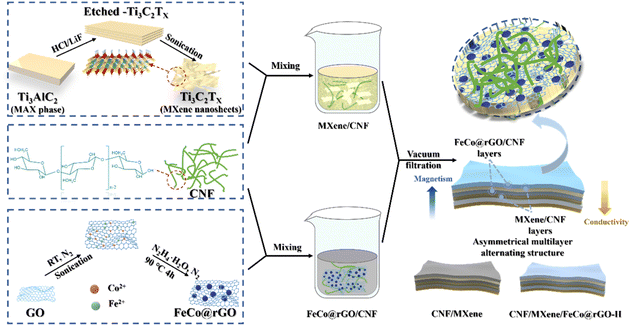
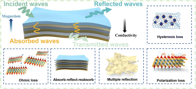
In this work, the electrically conductive and magnetic FeCo@rGO was combined with CNF and MXene, and an asymmetric gradient alternating multilayered composite film was constructed by regulating the distribution of FeCo@rGO and MXene in each layer. As a 3D magnetic and conductive material, FeCo@rGO increases the loss of electromagnetic waves through resistance loss and hysteresis loss. Due to its high conductivity and large specific surface area, MXene forms a “brick-paste structure” with CNF by non-covalent bonding, which takes into account both thermal conductivity and electromagnetic shielding performance, and ensures its mechanical strength at the same time. Owing to the design of the asymmetric gradient alternating structure, the total shielding efficiency of the asymmetric gradient alternating six-layer composite film reached 45.2 dB, which is much higher than that of the blend composite film (24.9 dB). The introduction of the asymmetric gradient alternating multilayer structure enhanced the impedance matching characteristics, enriched the electromagnetic wave attenuation characteristics, and thus improved the attenuation and absorption capacity of the composite film for electromagnetic waves, with the absorption coefficient increasing to 0.29. Owing to the high conductivity of the thin film and the new shielding mechanism, the electromagnetic wave has gradient absorption and gradient reflection in the layer. In addition, the composite film showed thermal conductivity of 2.90 W (m−1 K−1) and tensile strength of 26.22 MPa.
2 Experimental
2.1 Materials
Hydrazine hydrate (N2H4·H2O) was purchased from Shanghai Lingfeng Chemical Reagent Co., Ltd. Graphene (GO) was provided by Hangzhou Gaoxi Technology Co., Ltd. Cobalt chloride hexahydrate (CoCl2·6H2O), sodium hydroxide (NaOH), lithium fluoride (LiF), and ferrous sulfate heptahydrate (FeSO4·7H2O) were purchased from Aladdin Industrial Corporation. Cellulose nanofiber was sourced from Zhongshan Nanofibrils New Material Co., Ltd. Hydrochloric acid (HCl) was supplied by Sinopharm Co., Ltd (Shanghai, China). 200 mesh Ti3AlC2 powder was sourced from Forsman Scientific (Beijing) Co., Ltd.2.2 Synthesis of MXene and FeCo@rGO
MXene nanosheets were prepared by in situ hydrofluoric etching and ultrasonic stripping Ti3AlC2, as previously described.43,44 Ferrocobalt magnetic nanoparticle-decorated reduced graphene oxide (FeCo@rGO) was synthesized by ultrasonic coreduction method. Briefly, 100 mg of GO was added into a three-neck flask containing 100 mL of deionized water, and a uniform dispersion solution was obtained through ultrasonic dispersion. Then, 1.2 g of CoCl2·6H2O and 1.4 g of FeSO4·7H2O were weighed and placed into the flask, and ultrasonication was carried out for 90 min under a nitrogen atmosphere. The flask was placed in a 90 °C oil bath, and a solution containing 30 mL of hydrazine hydrate and 2.5 g of NaOH was slowly added using a constant pressure drip funnel. The solution was reacted in nitrogen atmosphere for 4 h. After the reaction, magnetic separation was used to wash the solution five times until the solution was neutral. After freeze-drying and grinding, FeCo@rGO was obtained; FeCo could adhere to the rGO via covalent bonding (Fig. 1).2.3 Preparation of CNF/MXene/FeCo@rGO composite film
FeCo@rGO was introduced into the system to construct the multilayered composite film with asymmetric gradient structure. The controlled dosage for the composite film was 180 mg of CNF, 90 mg of MXene, and 180 mg of FeCo@rGO. 10 mg mL−1 solutions of CNF, MXene, and FeCo@rGO were prepared by ultrasonic dispersion. CNF/MXene-X dispersion and CNF/FeCo@rGO-X dispersion were prepared according to the formula (Table S1†) (CNF/MXene-X means there is X wt% MXene in the CNF/MXene blend composite; CNF/FeCo@rGO-X means there is X wt% FeCo@rGO in the CNF/FeCo@rGO blend composite).For comparison, CNF/MXene and CNF/MXene-G/FeCo@rGO-H control groups were set. According to the order of CNF/MXene-100, CNF, CNF/MXene-60, CNF, CNF/MXene-20, and CNF, the dispersion solution was filtered to obtain a six-layered asymmetric conductivity gradient alternating composite film without magnetic particles, which is named CNF/MXene. According to the order of CNF/MXene-100, CNF/FeCo@rGO-60, CNF/MXene-60, CNF/FeCo@rGO-60, CNF/MXene-20, and CNF/FeCo@rGO-60, the dispersion solution was filtered to obtain a six-layered asymmetric gradient alternating composite film without magnetic gradient, which is named CNF/MXene/FeCo@rGO-H. The 20 wt%-6L composite film is renamed CNF/MXene/FeCo@rGO-G in Section 3.3, where G represents the magnetic gradient alternating structure and H represents the homogeneous blended composite with no magnetic gradient.
2.4 Characterization
The phase structures of the FeCo@rGO were analyzed via X-ray diffraction (XRD) with Cu Kα radiation (λ = 0.15406 nm) using an Ultima IV X-ray diffractometer from Rigaku (Japan). The magnetic properties were evaluated at room temperature using a PPMS-9 made by Quantum Design (USA). X-ray photoelectron spectroscopy (XPS) analysis was carried out via an ESCALAB 250 spectrometer. The morphologies and elemental mapping of FeCo@rGO and the fracture surface of composite films were determined using a using scanning electron microscope (S-4700 FE-SEM). The electrical conductivity was estimated using an RTS-8 four-probe resistivity meter (China). The EMI SE of the samples was tested by using a 3572C-S vector network analyzer from China Electric Power Kosi Technology Co., Ltd. The reflection coefficient (R), absorption coefficient (A), transmission coefficient (T), reflection (SER), absorption (SEA), total EMI SE (SET), and multiple reflection (SEM) were calculated using the following formulae based on scattering parameters directly recorded on VNA (S11 and S21):| R = |S11|2 = |S22|2 | (1) |
| T = |S21|2 = |S12|2 | (2) |
| A = 1 − (R + T) | (3) |
SER = −10![[thin space (1/6-em)]](https://www.rsc.org/images/entities/char_2009.gif) lg(1 − R) lg(1 − R) | (4) |
 | (5) |
| SET = SER + SEA | (6) |
The electrical conductivity of each sample was measured five times to ensure the accuracy of the data. The thermal diffusivity (α) of the composite film was measured at 25 °C using an LFA 467 (Netzsch, Germany) laser heat conduction instrument. The diameter of the sample was 25.4 mm. The specific heat capacity (Cp) of the sample was measured using a TA Q2000 DSC, in which the films were heated at the rate of 5 °C min−1 under the nitrogen atmosphere, and calculated by the sapphire three wire method. The density (ρ) of the sample was calculated in accordance with the mass–volume ratio of the sample. The thermal conductivity (TC) of the composite film was calculated using the following formula:
| TC = α × Cp × ρ | (7) |
The mechanical capacity of the composite film was estimated using an Instron 5966 high and low temperature double-column testing machine. The sample size was 10 mm (L) × 4 mm (W), and the drawing rate was 10 mm min−1. At least five samples should be taken to guarantee the correctness of the results.
3 Results and discussion
3.1 Morphology of MXene and FeCo@rGO
The Ti3C2Tx MXene, after selective etching of the Al layer, exhibits a typical accordion-like multilayer structure (Fig. S1a†). The presence of Ti, C, F, O, and their spatially separated distribution on the surface of MXene was investigated by energy dispersive X-ray spectroscopy (EDS) mapping in SEM. It indicates that functionalities such as –O, –F, or –OH appear on the surface of MXene after selective etching of the Al layer. Polarization loss occurred in the functional groups (–OH, –F, etc.) on the surface when the electromagnetic wave encountered the MXene nanosheets (Fig. S2b†). After ultrasonic peeling, the TEM of the d-MXene is shown in Fig. S1b.† The d-MXene presents a typical 2D layered structure with clear edges. Fig. S1c† shows typical XRD patterns of MAX and d-MXene. The (004) crystal plane corresponding to the Al layer is basically invisible in the spectrum, the characteristic peak corresponding to the (002) crystal plane moves forward, the 2θ value moves from 9.38° to 5.84°, and the layer spacing of MXene nanosheet increases by 5.7 Å, indicating the successful preparation of MXene.In order to prove the successful preparation of FeCo@rGO, it was characterized by SEM, XRD, and VSM. The typical wrinkled morphology and high surface area of reduced graphene oxide (rGO) provide sufficient space on its surface for the in situ growth of FeCo. According to the analysis in Fig. 3(a), it was found that many irregular polyhedra were anchored on the lamellar surface by ultrasonic coreduction. XRD was used to further investigate the crystal structure of the FeCo@rGO nanocomposite particles (Fig. 3(b)). The strong diffraction peaks at 31.2°, 44.8°, 65.3°, 74.1°, and 82.7° correspond to the (100), (110), (200), (210), and (211) planes of FeCo, respectively,45 consistent with standard card (JCPDS no. 44-1433). Other weak peaks in the spectrum are due to the oxidation of Fe to CoFe2O4 and FeFe2O4,46 suggesting that the modification of FeCo nanoparticles on the surface of the rGO sheets was successful. Fig. 3(c) shows the hysteresis loop curve for FeCo@rGO. In N2 atmosphere, FeCo@rGO prepared by ultrasonic coreduction showed saturation magnetization of 54 emu g−1, indicating good magnetic properties.
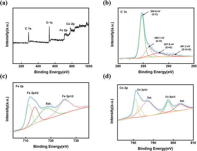
The surface chemistry of FeCo@rGO was further investigated by high-resolution C 1s, Fe 2p, and Co 2p XPS spectra (Fig. 4). The C 1s spectrum can be divided into four peaks (Fig. 4(b)). The strong peak at 284.6 eV corresponds to C–C, while the weak peaks at 286.1 eV and 287.9 eV were attributed to C–O and C![[double bond, length as m-dash]](https://www.rsc.org/images/entities/char_e001.gif) O, respectively. In addition, the peak at 291.2 eV confirmed the presence of O–C
O, respectively. In addition, the peak at 291.2 eV confirmed the presence of O–C![[double bond, length as m-dash]](https://www.rsc.org/images/entities/char_e001.gif) O, but the strength was significantly weaker. The reduction of the carbon–oxygen intensity indicates that many oxygen-containing groups are reduced and GO is reduced to rGO. In the Fe 2p spectrum (Fig. 4(c)), there are two broad peaks for Fe 2p3/2 and Fe 2p1/2 at 712.4 eV and 724.8 eV, respectively, among which there is a companion peak at around 718.1 eV, indicating that the sample contains a variety of valence states (Fe2+ and Fe3+). As Fig. 4(d) shows, the XPS map of Co presents two main peaks at 780.8 eV and 796.6 eV, which respectively correspond with Co 2p3/2 and Co 2p1/2. The accompanying peaks at 784.9 eV and 802.1 eV are attributed to Co3+ and Co2+, respectively, which is consistent with the XRD analysis results.
O, but the strength was significantly weaker. The reduction of the carbon–oxygen intensity indicates that many oxygen-containing groups are reduced and GO is reduced to rGO. In the Fe 2p spectrum (Fig. 4(c)), there are two broad peaks for Fe 2p3/2 and Fe 2p1/2 at 712.4 eV and 724.8 eV, respectively, among which there is a companion peak at around 718.1 eV, indicating that the sample contains a variety of valence states (Fe2+ and Fe3+). As Fig. 4(d) shows, the XPS map of Co presents two main peaks at 780.8 eV and 796.6 eV, which respectively correspond with Co 2p3/2 and Co 2p1/2. The accompanying peaks at 784.9 eV and 802.1 eV are attributed to Co3+ and Co2+, respectively, which is consistent with the XRD analysis results.
3.2 Microstructure of the composite films
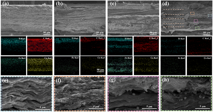
Scanning electron microscopy was used to investigate the cross-sectional elements and characterize the morphology of the hybrid composite film and the asymmetric gradient alternating multilayer composite films, as shown in Fig. 5. Under the same composition and content, the thickness of the composite films was similar, which was 20 wt%-1L (189 μm), 20 wt%-2L (197 μm), 20 wt%-4L (194 μm), and 20 wt%-6L (192 μm). No noticeable stratification could be seen between the CNF/MXene layers and the CNF/FeCo@rGO layers, as can be seen in Fig. 5(b–d), indicating good interaction between the layers. Different from the uniform distribution of Ti, Co, Fe, and other elements in the blend composite films, the asymmetric gradient alternating multilayer composite films all show the gradient change of Ti element, which confirms the existence of the gradient distribution and conductive gradient of MXene. In addition, Fe and Co elements show the opposite gradient change to Ti elements. It can be observed from the element distribution diagram that the films show asymmetric and gradient alternating multilayer structures. After amplifying the cross section of 20 wt%-6L by 12![[thin space (1/6-em)]](https://www.rsc.org/images/entities/char_2009.gif) 000 times, the layer of CNF/FeCo@rGO (Fig. 5(f–h)) shows many irregular polyhedra FeCo anchored on the surface of the rGO layer, while the layer of CNF/MXene (Fig. 5(e)) shows a dense layered structure arranged in the parallel direction. According to the EDS elements and morphologies, the 20 wt%-6L cross section can be divided into six layers, and the FeCo particles increase from Fig. 5(f)–(h), confirming the gradient distribution of the composite films. In summary, it is proved that CNF/MXene/FeCo@rGO composite membranes with asymmetric gradient alternating multilayer structure have been successfully prepared by successive filtration methods.
000 times, the layer of CNF/FeCo@rGO (Fig. 5(f–h)) shows many irregular polyhedra FeCo anchored on the surface of the rGO layer, while the layer of CNF/MXene (Fig. 5(e)) shows a dense layered structure arranged in the parallel direction. According to the EDS elements and morphologies, the 20 wt%-6L cross section can be divided into six layers, and the FeCo particles increase from Fig. 5(f)–(h), confirming the gradient distribution of the composite films. In summary, it is proved that CNF/MXene/FeCo@rGO composite membranes with asymmetric gradient alternating multilayer structure have been successfully prepared by successive filtration methods.
3.3 Conductivity and EMI shielding properties of the composite films
The conductivity of CNF/MXene composite films with various MXene concentrations is shown in Fig. 6(a). It was discovered that the conductivity of the composite films increases with increasing MXene content, which lays a foundation for the subsequent construction of asymmetric gradient and magnetic gradient alternating multilayer composite films. Maintaining the composition and content of the CNF/MXene/FeCo@rGO composite films, the asymmetric gradient alternating multilayer composite films with different layers were prepared by adjusting the distribution of filler, and the electromagnetic shielding performance of the composite films was studied. As can be seen from Fig. 6(b), the 2L, 4L, and 6L composite films with asymmetric structure show higher total shielding efficiency than the blend composite films with the identical components and contents. For instance, the average SET of the asymmetric gradient alternating six-layer multifilm reached 45.2 dB in the X-band. According to Simon's formula, the conductivity and thickness of the materials have a positive relationship with the electromagnetic shielding effectiveness of conductive composite materials. Previously, it was observed that the thickness of the blended composite film was similar to that of the asymmetric composite films, but the total shielding efficiency increased as the number of layers increased, which may be attributed to the design of the asymmetric gradient alternating multilayer structure. The SER, SEA, and SET values of the asymmetric gradient alternating multilayer composite films are shown in Fig. 6(c). The SER values of the 20 wt%-2L, 20 wt%-4L, and 20 wt%-6L multilayer composite films were not significantly higher compared with that of the 20 wt%-1L blend composite film, but the SEA values were much higher than that of the blend composite film, and the increase of the SET was mainly due to the contribution of SEA. It is widely recognized that SEA mainly relies on the dielectric and magnetic properties of a material. Hence, we can draw the conclusion that the increased dielectric loss and magnetic loss of the material are the main causes of the increased SEA. Polarization loss and ohmic loss are the two basic types of dielectric loss. The two primary processes that lead to microwave attenuation in the gigahertz range have been proposed to be dipole polarization and interface polarization in polarization loss. Strong polarization loss occurs as a result of the centering of dipole polarization on crystal defects and surface groups. Therefore, due to the defects on the surface of rGO and the presence of oxygen-containing groups, polarization loss is caused. There is an interfacial polarization loss between rGO and FeCo, and the magnetic loss of FeCo enables the composite membrane to effectively absorb electromagnetic waves. Also, according to EDS mapping in SEM (Fig. S2b†) of the surface of the MXene, surface functionalities such as –O, –F, or –OH appeared on the surface of the MXene, after selective etching of the Al layer. The polarization loss occurred in the functional groups (–OH, –F, etc.) on the surface when the electromagnetic wave encountered the MXene nanosheets.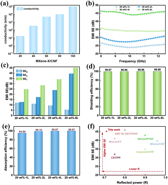 | ||
| Fig. 6 (a) Conductivity of CNF/MXene composite films with different MXene contents. (b) EMI SE, (c) SER, SEA, and SET. (d) Shielding efficiency and (e) absorption efficiency of blended composite films and asymmetric gradient alternating multilayer composite films. (f) Comparison of EMI SE versus reflected power with reported materials.24,43,47–50 | ||
Fig. 6(d) shows the shielding efficiency of the composite films. According to the results, the shielding efficiency of the blended composite films and the asymmetric gradient alternating multilayer composite films is more than 99%, and the shielding efficiency of the six-layer composite membrane is as high as 99.99%, indicating that the asymmetric gradient alternating multilayer composite membrane can effectively shield electromagnetic waves. For electromagnetic waves entering the composite membrane, absorption efficiency (Aeff) was further introduced to better understand the dissipative mechanism (Fig. 6(e)), where  Compared with the blended composite film of 20 wt%-1L, the Aeff of the asymmetric gradient alternating multilayer composite film with the structural design is more than 99%, and the Aeff of 20 wt%-6L is up to 99.97%, showing the strong ability to absorb incident electromagnetic waves.
The work was compared with the reported literature, as shown in Fig. 6(f). Thanks to the asymmetric gradient alternating multilayer design, the average electromagnetic shielding performance reached 45.2 dB and R-value was as low as 0.71 at six layers. The structure makes the composite films show better electromagnetic shielding and electromagnetic wave absorption performance at lower content. The performance of the asymmetric gradient alternating multilayer composite films is compared in detail in Table S2† to literature reports.
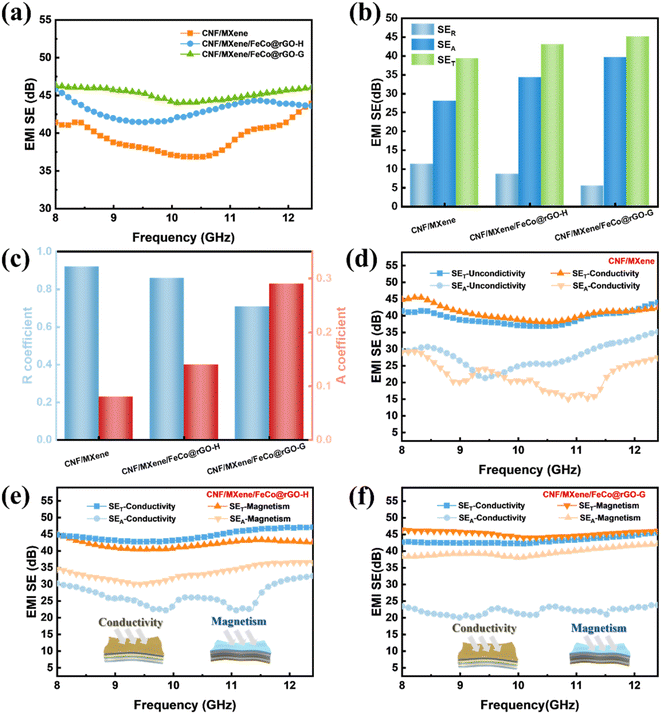
For comparison, we prepared a pristine MXene film (90 mg) (Fig. S3†) six-layer conductivity gradient composite membrane, CNF/MXene, which includes 90 mg of MXene (Fig. 7). The pristine MXene film was easily oxidized and showed poor chemical stability. After 7 days, the EMI SE of MXene decreased from 50 dB to 37 dB. Moreover, constructed six-layer conductivity gradient composites CNF/MXene with CNF, R-value of CNF/MXene was 0.91 compared with MXene 0.99, enhanced absorbing electromagnetic interference shielding. This is because the addition of CNF and the construction of the gradient distribution structure improves the impedance matching of the MXene.
Furthermore, for the sake of demonstrating the influence of the magnetic gradient formed by FeCo@rGO on the electromagnetic shielding performance of the composite film, CNF/MXene and CNF/MXene/FeCo@rGO-H were set as the control group of CNF/MXene/FeCo@rGO-G, that is, 20 wt%-6L. As we can see in Fig. 7(a), the total shielding efficiency of the CNF/MXene composite membrane in the X-band is lower than that of CNF/MXene/FeCo@rGO-H and CNF/MXene/FeCo@rGO-G, mainly because of FeCo@rGO having a certain electrical conductivity. Fig. 7(b) illustrates the average SER, SEA, and SET values of the composite membrane, and it is evident that the SEA values are significantly higher than the SET values, and the SEA value of the CNF/MXene/FeCo@rGO-G composite film reached nearly 40 dB. Fig. 7(c) shows that the absorption coefficient of the CNF/MXene composite film with only a conductive gradient is less than 0.1. The introduction of magnetic FeCo@rGO improved the absorption coefficient to a certain extent, indicating that magnetic particles improve the electromagnetic wave shielding absorption. The further construction of alternating magnetic and conductive gradient structure increased the absorption coefficient to 0.29.
The impact of various incidence directions on the electromagnetic shielding performance of the composite film was investigated in order to further clarify the role of the asymmetric gradient alternating multilayer structure, as shown in Fig. 7(d–f). Changing the incident direction affects the reflection efficiency of the composite film rather than the overall shielding efficiency. Altering the incident direction effectively changes the electromagnetic wave's transmission path, which has an impact on the wave's attenuation. When the incident direction is along the conductive gradient, the incident electromagnetic wave first contacts the reflective layer, resulting in impedance mismatch, and only a small amount of electromagnetic wave enters the composite film in order to further produce dielectric loss, magnetic loss, and many reflections, leading to an exceptionally high reflection efficiency. In contrast, the incident electromagnetic wave is incident in the direction of the magnetic gradient, and the low-conductive magnetic layer and the air have good impedance matching. Most electromagnetic beams can easily penetrate the interior of the CNF/MXene/FeCo@rGO thin film with negligible reflection when the incident electromagnetic beam strikes the low-conductive surface, and eventually gradient absorption and reflection will occur inside. The electromagnetic wave energy is effectively turned into heat energy and other energy inside the composite film, and the reflection efficiency is lower. The SEA difference between the two incident directions of the composite film with asymmetric gradient alternating multilayer structure reached nearly 17 dB.
The electromagnetic shielding mechanism of the CNF/MXene/FeCo@rGO composite films with an asymmetric gradient alternating layer structure is presented in light of the aforementioned experimental results, as shown in Fig. 8. As the number of layers increases, the electromagnetic shielding efficiency increases significantly, indicating that the increase of the electromagnetic shielding efficiency is mainly attributed to the asymmetric gradient alternating multilayer structure. Take the six-layer structure for example, due to the dielectric loss and magnetic loss of FeCo@rGO, an electromagnetic wave that hits the absorption layer on the surface of the composite film is partially absorbed by the layer and partially reflected, and a small part is reflected. Due to impedance mismatch, a small portion of the electromagnetic wave that has passed through the absorption layer and reached the CNF/MXene reflector is reflected at the interface between the absorption layer and the reflector layer before being reabsorbed by the absorption layer. A small fraction of the electromagnetic wave that enters the reflected layer interacts with high-density carriers (such as dipoles, holes, electrons, etc.), generating ohmic loss of the electromagnetic wave, which leads to absorption and attenuation of the electromagnetic wave. The characteristic asymmetric gradient structure enables continuous gradient reflection and gradient absorption of electromagnetic waves in the composite film, considerably enhancing its electromagnetic shielding capabilities.
3.4 Thermal conductivity of the composite films
The buildup of heat inside an electronic device will certainly reduce performance and possibly result in device damage considering its rapid development. When exposed to electromagnetic radiation for an extended period of time, electromagnetic shielding materials are at risk of overheating. As a consequence, electromagnetic shielding materials with high thermal conductivity have become an urgent need. As previously reported, the thermal conductivity of the CNF composite membrane is 1.02 W (m−1 K−1). Compared with the CNF composite film, the mixed composite film's thermal conductivity was 272% greater, reaching 3.8 W (m−1 K−1) (Fig. 9(a)). The thermal conductivity of the composite film marginally dropped as an asymmetric gradient alternating multilayer structure was built, but it still remained 189% higher than that of the CNF composite film at 2.90 W (m−1 K−1) for 20 wt%-6L. | ||
| Fig. 9 (a) Thermal conductivity. (b) Thermal conductivity diagram for CNF/MXene/FeCo@rGO-20 wt%-1L blended composite film and asymmetric gradient alternating multilayer nanocomposite films. | ||
As shown in Fig. 9(b), MXene forms a heat conduction network throughout the film, providing a path for phonon conduction, and heat can dissipate effectively along the MXene/CNF layer, thus greatly enhancing the in-plane thermal conductivity of the multilayer film compared with the CNF composite film. However, as the number of layers increases, the interface thermal resistance increases, leading to the decrease of the thermal conductivity.
3.5 Mechanical properties of the composite films
In addition, multifunctional electromagnetic shielding materials need to have certain mechanical properties to meet the needs of use. The mechanical properties of the composite membrane were further studied. The stress–strain curves of the blend composite film and the asymmetric gradient alternating multilayer composite films are shown in Fig. 10(a), and the tensile stress and Young's modulus are shown in Fig. 10(b). It can be seen that the tensile strength of the blended composite film is 32.9 MPa. The tensile strength of 20 wt%-2L increases with the number of layers, reaching 30.3 MPa, 20 wt%-4L is 29.8 MPa, and 20 wt%-6L is 26.2 MPa, which is slightly lower than that of the blend composite film. The above results are mainly attributed to the defects between interfaces caused by the multilayer structure. But in general, the asymmetric gradient alternating multilayer composite films still maintain good mechanical properties. When subjected to external force, due to the weak bond between CNF and FeCo@rGO, fracture occurs first. However, the hydrogen bond formed between CNF and MXene increases the energy dissipation and can keep the composite membrane intact. When the stress is further increased to the critical load of the CNF/MXene layer, the cracks slip along the interface between the CNF/FeCo@rGO layer and form a Z-shaped crack path. The resulting layered Z cracks greatly increase the tensile strength of the material. From the morphology of the tensile section of the composite film (Fig. 11(a–c)), it can be seen that the composite film does not show obvious stratification, and still maintains the original dense layered structure. Increasing the number of layers, the stratification phenomena was more obvious after stretching. As we can see in Fig. 11(d), detachment occurs between the CNF/FeCo@rGO layers and the CNF/MXene layers, because there are defects between the interfaces.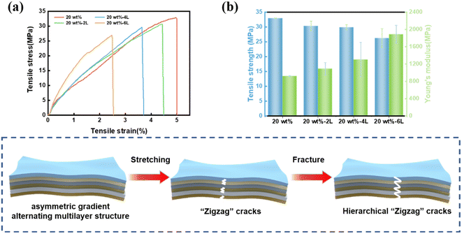 | ||
| Fig. 10 (a) Stress–strain curves, (b) tensile strength and Young's modulus of the blended composite film and the asymmetric gradient alternating multilayered composite films. | ||
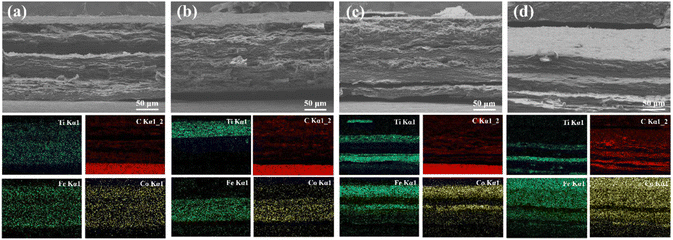 | ||
| Fig. 11 SEM images of fracture surface of (a) 20 wt%-1L, (b) 20 wt%-2L, (c) 20 wt%-4L, and (d) 20 wt%-6L, and corresponding EDS mappings of Ti, C, Fe, and Co elements. | ||
4 Conclusions
By introducing FeCo@rGO with combined electrical and magnetic properties and constructing an asymmetric gradient alternate multilayer structure composite film CNF/MXene/FeCo@rGO, it has been demonstrated that the design of the structure facilitates the reasonable allocation of fillers, achieving high-efficiency electromagnetic shielding at low filler content. The total shielding effectiveness of the composite film reached 45.2 dB and the R-value was as low as 0.71. The ultra-high electromagnetic interference shielding performance of the composite film is mainly due to its high electrical conductivity and the shielding mechanism resulting from the gradient absorption and reflection of electromagnetic waves in the thin film. Additionally, the thermal conductivity of the composite film is 2.90 W (m−1 K−1). This innovative method for designing asymmetric gradient alternative multilayer structures offers a suggestion for the preparation of multifunctional composite films with ultra-high electromagnetic interference shielding performance, efficient thermal conductivity performance, and excellent mechanical properties.Author contributions
Meng Ma: conceptualization, supervision, writing-original draft, review and editing. Wenqin Shao: investigation, data curation, writing-original draft. Qindan Chu: data analysis, discussion, writing-original draft. Wenting Tao: conceptualization, data analysis, discussion. Si Chen: methodology, investigation, data curation. Yanqin Shi: methodology, investigation, data curation. Huiwen He: methodology, investigation, data curation. Yulu Zhu: methodology, investigation, data curation. Xu Wang: conceptualization, supervision, writing-review and editing.Conflicts of interest
There are no conflicts to declare.Acknowledgements
This work was supported by the National Natural Science Foundation of China (grant no. 52273044, 52373092), the Opening Project of the State Key Laboratory of Polymer Materials Engineering (Sichuan University) (grant no. sklpme2023-3-4), the Key Research Program of Zhejiang Province (grant no. 2023C01101, 2023C01210, 2022C01049, 2022C01205, 2022C01228), and the Natural Science Foundation of Zhejiang Province (grant no. LY20E030008).References
- J. C. Lin, IEEE Microwave Mag., 2016, 17, 32–36 Search PubMed.
- J. Karpowicz, P. Zradziński, J. Kieliszek, K. Gryz, J. Sobiech and W. Leszko, BioMed Res. Int., 2017, 2017, 1–9 CrossRef PubMed.
- A. Hua, D. Pan, Y. Li, J. Luan, Y. Wang, J. He, D. Geng, W. Liu, S. Ma and Z. Zhang, J. Magn. Magn. Mater., 2019, 471, 561–567 CrossRef CAS.
- Z. Wang, Z. Cheng, C. Fang, X. Hou and L. Xie, Composites, Part A, 2020, 136, 105956 CrossRef CAS.
- A. Siriwitpreecha, P. Rattanadecho and T. Wessapan, Int. J. Heat Mass Transfer, 2013, 65, 423–434 CrossRef.
- X. Yang, X. Zhong, J. Zhang and J. Gu, J. Mater. Sci. Technol., 2021, 68, 209–215 CrossRef CAS.
- J. Cheng, C. Li, Y. Xiong, H. Zhang, H. Raza, S. Ullah, J. Wu, G. Zheng, Q. Cao, D. Zhang, Q. Zheng and R. Che, Nano-Micro Lett., 2022, 14, 80 CrossRef CAS.
- Q. Wei, S. Pei, X. Qian, H. Liu, Z. Liu, W. Zhang, T. Zhou, Z. Zhang, X. Zhang, H. M. Cheng and W. Ren, Adv. Mater., 2020, 32, e1907411 CrossRef PubMed.
- Y. Bhattacharjee and S. Bose, ACS Appl. Nano Mater., 2021, 4, 949–972 CrossRef CAS.
- H. Xu, X. Yin, X. Li, M. Li, S. Liang, L. Zhang and L. Cheng, ACS Appl. Mater. Interfaces, 2019, 11, 10198–10207 CrossRef CAS PubMed.
- R. Bera, A. Maitra, S. Paria, S. K. Karan, A. K. Das, A. Bera, S. K. Si, L. Halder, A. De and B. B. J. C. E. J. Khatua, Chem. Eng. J., 2018, 335, 501–509 CrossRef CAS.
- L. X. Liu, W. Chen, H. B. Zhang, Q. W. Wang, F. Guan and Z. Z. Yu, Adv. Funct. Mater., 2019, 29, 1905197 CrossRef CAS.
- L. Wang, Y. Chen, L. Lin, H. Wang, X. Huang, H. Xue and J. Gao, Chem. Eng. J., 2019, 362, 89–98 CrossRef CAS.
- L. C. Jia, G. Zhang, L. Xu, W. J. Sun, G. J. Zhong, J. Lei, D. X. Yan and Z. M. Li, ACS Appl. Mater. Interfaces, 2019, 11, 1680–1688 CrossRef CAS PubMed.
- L. Lu, Y. Zhou, J. Pan, T. Chen, Y. Hu, G. Zheng, K. Dai, C. Liu, C. Shen, X. Sun and H. Peng, ACS Appl. Mater. Interfaces, 2019, 11, 4345–4352 CrossRef CAS.
- R. Hsissou, R. Seghiri, Z. Benzekri, M. Hilali, M. Rafik and A. Elharfi, Compos. Struct., 2021, 262, 113640 CrossRef CAS.
- D. Wanasinghe and F. Aslani, Composites, Part B, 2019, 176, 107207 CrossRef CAS.
- J. Huang, S. Daryadel and M. Minary-Jolandan, ACS Appl. Mater. Interfaces, 2019, 11, 4364–4372 CrossRef CAS.
- D. Hu, X. Huang, S. Li and P. Jiang, Compos. Sci. Technol., 2020, 188, 107955 CrossRef.
- H. Zhao, Y. Huang, J. Yun, Z. Wang, Y. Han, Y. Zheng and L. Chen, Composites, Part A, 2022, 157, 107077 CrossRef.
- Y. Zhang, X.-x. Fang and B.-y. Wen, Chin. J. Polym. Sci., 2015, 33, 899–907 CrossRef CAS.
- Z. Wu, Y. Yao, Q. Su, X. Lv and Q. Shu, J. Alloys Compd., 2023, 940, 168848 CrossRef CAS.
- H. Zhang, G. Zhang, Q. Gao, M. Tang, Z. Ma, J. Qin, M. Wang and J.-K. Kim, Chem. Eng. J., 2020, 379, 122304 CrossRef.
- Y. Liu, Z. Zhang, X. Yang, F. Li, Z. Liang, Y. Yong, S. Dai and Z. Li, J. Mater. Chem. A, 2023, 11, 6603–6614 RSC.
- T. Liu, N. Zhang, K. Zhang, Y. Wang, Y. Qi and M. Zong, Composites, Part A, 2022, 159, 107020 CrossRef CAS.
- M. Ma, W. Tao, X. Liao, S. Chen, Y. Shi, H. He and X. Wang, Chem. Eng. J., 2023, 452, 139471 CrossRef CAS.
- Q. Peng, M. Ma, Q. Chu, H. Lin, W. Tao, W. Shao, S. Chen, Y. Shi, H. He and X. Wang, J. Mater. Chem. A, 2023, 11, 10857–10866 RSC.
- J. Liu, H. B. Zhang, R. Sun, Y. Liu, Z. Liu, A. Zhou and Z. Z. Yu, Adv. Mater., 2017, 29, 1702367 CrossRef.
- Z. Zong, P. Ren, Z. Guo, J. Wang, Z. Chen, Y. Jin and F. Ren, J. Colloid Interface Sci., 2022, 619, 96–105 CrossRef CAS PubMed.
- X. Tang, J. Luo, Z. Hu, S. Lu, X. Liu, S. Li, X. Zhao, Z. Zhang, Q. Lan, P. Ma, Z. Wang and T. Liu, Nano Res., 2022, 16, 1755–1763 CrossRef.
- W.-C. Yu, G.-Q. Zhang, Y.-H. Liu, L. Xu, D.-X. Yan, H.-D. Huang, J.-H. Tang, J.-Z. Xu and Z.-M. Li, Chem. Eng. J., 2019, 373, 556–564 CrossRef CAS.
- C. Ge, G. Wang, G. Zhao, C. Wei and X. Li, Composites, Part A, 2021, 144, 106356 CrossRef CAS.
- K. Rajavel, Y. Hu, P. Zhu, R. Sun and C. Wong, Chem. Eng. J., 2020, 399, 125791 CrossRef CAS.
- C. Weng, T. Xing, H. Jin, G. Wang, Z. Dai, Y. Pei, L. Liu and Z. Zhang, Composites, Part A, 2020, 135, 105927 CrossRef CAS.
- M. Ma, X. Liao, Q. Chu, S. Chen, Y. Shi, H. He and X. Wang, Compos. Sci. Technol., 2022, 226, 109540 CrossRef CAS.
- X. Zhou, S. Li, M. Zhang, X. Yuan, J. Wen, H. Xi, H. Wu and X. Ma, Carbon, 2023, 204, 538–546 CrossRef CAS.
- C.-H. Cui, D.-X. Yan, H. Pang, X. Xu, L.-C. Jia and Z.-M. Li, ACS Sustain. Chem. Eng., 2016, 4, 4137–4145 CrossRef CAS.
- J. Hu, C. Liang, J. Li, C. Lin, Y. Liang and D. Dong, ACS Appl. Mater. Interfaces, 2022, 14, 33817–33828 CrossRef CAS.
- A. Sheng, W. Ren, Y. Yang, D.-X. Yan, H. Duan, G. Zhao, Y. Liu and Z.-M. Li, Composites, Part A, 2020, 129, 105692 CrossRef CAS.
- W. Cao, C. Ma, S. Tan, M. Ma, P. Wan and F. Chen, Nano-Micro Lett., 2019, 11, 72 CrossRef CAS.
- B. Zhao, Z. Yan, Y. Du, L. Rao, G. Chen, Y. Wu, L. Yang, J. Zhang, L. Wu and D. W. Zhang, Adv. Mater., 2023, 35, 2210243 CrossRef CAS.
- B. Zhao, Y. Du, Z. Yan, L. Rao, G. Chen, M. Yuan, L. Yang, J. Zhang and R. Che, Adv. Funct. Mater., 2023, 33, 2209924 CrossRef CAS.
- L. Wang, L. Chen, P. Song, C. Liang, Y. Lu, H. Qiu, Y. Zhang, J. Kong and J. Gu, Composites, Part B, 2019, 171, 111–118 CrossRef CAS.
- Q. Chu, W. Tao, H. Lin, M. Ma, S. Chen, Y. Shi, H. He and X. Wang, Ind. Crops Prod., 2023, 194, 116299 CrossRef CAS.
- X. Fan, H. Gao, X. Kou, B. Zhang and S. Wang, Mater. Res. Bull., 2015, 65, 320–324 CrossRef CAS.
- X. Li, J. Feng, Y. Du, J. Bai, H. Fan, H. Zhang, Y. Peng and F. Li, J. Mater. Chem. A, 2015, 3, 5535–5546 RSC.
- L. Li, Z. Ma, P. Xu, B. Zhou, Q. Li, J. Ma, C. He, Y. Feng and C. Liu, Composites, Part A, 2020, 139, 106134 CrossRef CAS.
- Y. Li, B. Zhou, Y. Shen, C. He, B. Wang, C. Liu, Y. Feng and C. Shen, Composites, Part B, 2021, 217, 108902 CrossRef.
- Q. Qi, L. Ma, B. Zhao, S. Wang, X. Liu, Y. Lei and C. B. Park, ACS Appl. Mater. Interfaces, 2020, 12, 36568–36577 CrossRef CAS.
- Y.-P. Zhang, C.-G. Zhou, W.-J. Sun, T. Wang, L.-C. Jia, D.-X. Yan and Z.-M. Li, Compos. Sci. Technol., 2020, 197, 108253 CrossRef CAS.
Footnote |
| † Electronic supplementary information (ESI) available. See DOI: https://doi.org/10.1039/d3ta06467k |
| This journal is © The Royal Society of Chemistry 2024 |


