A high-efficiency NiFeSe4/NiSe2 bifunctional electrocatalyst with outstanding oxygen evolution reaction and overall water splitting performance†
Lan
Mu
,
Shipeng
Qiu
,
Gang
Zhao
 *,
Baojie
zhang
,
Wenbo
Liao
,
Ning
Zhao
and
Xijin
Xu
 *
*
School of Physics and Technology, University of Jinan, Jinan 250022, P. R. China. E-mail: sps_zhaog@ujn.edu.cn; sps_xuxj@ujn.edu.cn
First published on 7th December 2023
Abstract
Developing cost-effective electrocatalysts for overall water splitting is an effective approach to produce green hydrogen and oxygen. A NiFeSe4/NiSe2 heterostructure catalyst for high-efficiency HER and OER was effectively created using an in situ growth preparation approach in this study. The basic crystal structure of the material was altered by selenization, which facilitates electron redistribution within the material. Furthermore, the heterostructure formed following selenization can not only improve the material's conductivity but also give additional active area for catalysis. Meanwhile, the built-in electric field aided in electron redistribution. The NiFeSe4/NiSe2-8 h catalyst demonstrated excellent performance, requiring an overpotential of only 218 mV (OER) and 121 mV (HER) to achieve a current density of 10 mA cm−2. The overall water splitting reaction was carried out at 1.572 V using the NiFeSe4/NiSe2-8 h bifunctional catalyst as the cathode and anode of the reaction. Stability is also an important component in determining the quality of materials. The NiFeSe4/NiSe2-8 h material reacted continuously at diverse current densities (including low and high current densities) for 36 h with no noticeable performance loss. This work provides a feasible method for preparing an economical and efficient electrocatalyst by adjusting the electrocatalytic performance through heterojunction engineering.
Introduction
Electrocatalytic water splitting is seen as an effective way to generate green hydrogen and oxygen, which is essential in addressing the energy shortage and environmental contamination caused by carbon discharges.1–3 Harnessing wind, tidal, and other renewable, clean energy sources to generate energy for the purpose of water splitting is seen as an encouraging approach.4,5 As the product of water splitting, hydrogen has the advantages of clean combustion products, being renewable, and high energy density.4,6–9 The water splitting reaction consists of two half reactions, the cathodic HER reaction with two-electron transfer and the anodic OER reaction with four-electron transfer.6,8,10–15 Both half-reactions require extra energy to surpass the reaction barrier, thereby demanding effective catalysts to diminish the reaction's overpotential.8,10,16 Prior research studies have demonstrated the low overpotentials and good catalytic activity of noble metal-based catalysts, including RuO2, IrO2, and Pt, indicating their potential utility as effective water splitting catalysts.7,10,17–20 Nevertheless, their extensive utilization is constrained by their limited availability, exorbitant cost, and low durability.6,7,10,17,21,22 Therefore, economical, effective and reliable bifunctional catalysts are essential.Due to their abundance in the earth, low cost, and good electrocatalytic performance, transition metal (TM) compounds have been prepared as HER and OER electrocatalysts in recent years.23 Among them, NiFe layered double hydroxides (NiFe-LDH) exhibit good catalytic activity in the OER, even surpassing some noble metal catalysts.15,24–26 However, due to the slow water dissociation kinetics of this catalyst, there is a problem of poor catalytic activity for the HER.24 Simultaneously, NiFe-LDH has a limited surface area and low electrical conductivity, which leads to a high voltage for water splitting.13,24,25 Selenide exhibits superior electrical conductivity compared to other transition metals.27–29 Transition metal selenides (TMSes) possess comparable structures to sulfides. However, Se atoms possess a greater atomic radius,27 superior metallic properties, and lower ionization energy compared to S atoms, thereby enabling selenides to demonstrate superior conductivity compared to sulfides and a suitable electron configuration.30 Among TMSes, NiSe2 has high intrinsic conductivity, but its further applications are hindered by the shortcomings of low catalytic activity, small surface area, and poor durability.27,31
Consequently, to enhance the efficiency of catalysts, doping,32 alloying,33 and heterostructures34,35 are commonly employed. Among them, using heterostructures is an effective method.28,36,37 In heterojunction catalysts, electrons are rearranged on the heterojunction interface to modify the active sites, and the synergistic effect of different active sites can promote the reaction kinetics.38 In addition, heterojunctions can enable different components to maintain their respective properties.39 The catalyst's improved catalytic activity can be attributed to the robust electronic interaction among its various components.36 Extensive heterostructure interfaces increase the electrochemically active area,28 fully expose the active sites, and hence enhance the catalytic activity.36 For instance, Tan et al.35 successfully synthesized NiSe2/Ni3Se4 biphasic catalysts with good water splitting and HER performance. Interfacial electron transport was facilitated by the catalyst's heterogeneous structure. This heterostructure's effective construction raised the adsorption/desorption energy in addition to improving the conductivity.
In this work, a heterostructure of NiFeSe4/NiSe2 has been successfully designed and synthesized by a sensible strategy. The hetero-interfacial interaction between NiFeSe4 and NiSe2 provided a strong synergistic effect, which enhanced the interfacial charge transfer and electrical conductivity, which was beneficial to enhancing the performance of the catalyst. The NiFeSe4/NiSe2-8 h catalyst had excellent electrocatalytic performance. The HER and OER processes can occur at overpotentials of just 121 mV and 218 mV, respectively, with a current density of 10 A cm−2. When the NiFeSe4/NiSe2 bifunctional electrode was used as the cathode and anode, the water splitting reaction could only be conducted at a voltage of 1.572 V. Afterwards, at different current densities (10, 100 and 300 mA cm−2), overall water splitting was performed, and the performance did not decrease significantly within 36 h.
Experimental
Synthesis of the materials
Material characterization
A TESCAN MIRA LMS scanning electron microscope (SEM) was utilized to capture images of the sample's morphology and conduct mapping tests. XRD (Ultima IV) was used to analyze the physical composition of the materials. A Thermo Scientific K-Alpha XPS instrument was utilized to assess the valence state of the materials. The XPS instrument utilized Al Kα rays and underwent calibration with surface-contaminated C 1s as a benchmark. Lattice information and high-resolution TEM (HRTEM) images of the material were obtained using an FEI Talos F200x transmission electron microscope (TEM).Electrochemical measurements
The prepared materials underwent a series of basic electrochemical tests on a Shanghai Chenhua Electrochemical Workstation (CHI 760E). The electrolyte used in the three-electrode electrolyzer was a 1 M KOH solution, a silver chloride (Ag/AgCl) electrode was used as the reference electrode, and a platinum sheet was used as the counter electrode. No iR compensation was conducted in any of the tests included in this study. The electric double layer capacitance (Cdl) of the different materials was measured using cyclic voltammetry (CV) in the voltage range of 0.923–1.123 V vs. RHE. The CV scan rate was from 75 mV s−1 to 200 mV s−1, with increases of 25 mV s−1. The frequency range assessed in electrochemical impedance spectroscopy (EIS) was from 1 × 10⁵ Hz to 1 × 10⁻³ Hz. Stability tests were conducted through chronoamperometry. The data measured during the experiment were converted into an electrode potential relative to the reversible hydrogen electrode (RHE) according to the formula: E (vs. RHE) = E (vs. Ag/AgCl) + 0.197 V + 0.05916 × pH. All electrochemical tests were carried out with a potential sweep speed of 5 mV s−1.Results and discussion
Morphological and structural characterization
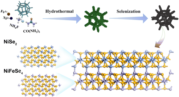
Fig. 1 shows the preparation process of the NiFeSe4/NiSe2 catalyst. NiFe-LDH nanosheets were synthesized on high-purity NF using an in situ growth method, and then selenized to successfully synthesize the NiFeSe4/NiSe2 catalysts. NF had good electrical conductivity, good stability and a porous structure, which can provide an excellent substrate for subsequent growth of the materials. First, uniformly grown NiFe-LDH nanosheets were successfully prepared on NF by a hydrothermal method. Then, the NiFeSe4/NiSe2 heterostructure was successfully constructed by solvothermal selenization of NiFe-LDH. Finally, NiFeSe4/NiSe2 materials with different morphologies were synthesized through different selenization times.The morphology of the different materials was characterized. The aforesaid process was used to successfully create NiFeSe4/NiSe2 heterostructures. The SEM image in Fig. 2 shows the surface characteristics of NiFeSe4/NiSe2. Due to the different selenization times, the morphology of the catalysts also had certain differences. Before selenization, NiFe-LDH nanosheets were produced uniformly on smooth NF. Fig. S1† depicts the precursor's SEM. The NF surface was smooth (Fig. S1a and b†), whereas the NiFe-LDH sample formed following hydrothermal reaction had a flake structure (Fig. S1c and d†). The solvothermal method was used to selenize the NiFe-LDH nanosheets. Among these, the addition of Se ions broke down the NiFe-LDH crystal structure, resulting in the dissociation of some Ni ions in the solvent and a Ni source for the NiSe2 particles that subsequently formed on the surface. Fig. 2 shows SEM images of the surface properties of NiFeSe4/NiSe2. Fig. 2a–c depict the morphology of the catalysts after 6 h, 8 h, and 10 h of selenization, with magnified SEM images added. The nanosheets were clearly related to the nanoparticles, and as the selenization period increased, the nanoparticles on the surface showed an increasing trend. A shorter selenization time may result in an incomplete reaction, whereas a longer selenization time will result in the formation of more NiSe2 nanoparticles, which may obstruct gas escape. As a result, materials made with an 8 hour selenization period had better characteristics than materials prepared with a 6 or 10 hour one. More information about the surface characteristics of the material with an 8 hour selenization time can be found in Fig. 2d–f. This reaction resulted in the formation of NiSe2 and NiFeSe4. As a result, the NiFeSe4/NiSe2 heterojunction structure was created successfully.
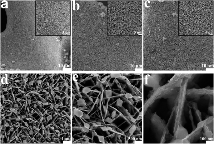 | ||
| Fig. 2 SEM images of catalysts prepared with different selenization times: (a) NiFeSe4/NiSe2-6 h; (b) NiFeSe4/NiSe2-8 h; (c) NiFeSe4/NiSe2-10 h; (d–f) zoomed-in views of the NiFeSe4/NiSe2-8 h. | ||
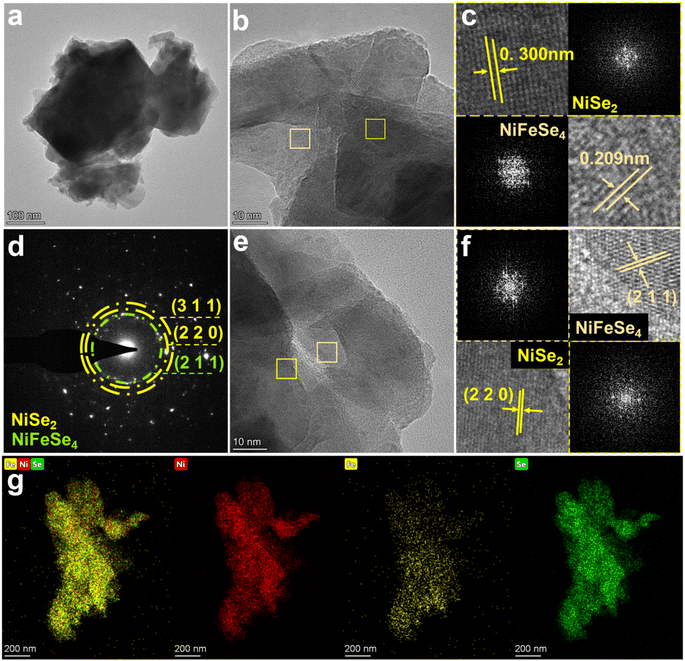
The structure of NiFeSe4/NiSe2-8 h was analyzed by TEM and HRTEM. The TEM image showed that NiFeSe4/NiSe2-8 h had a structure in which the nanosheets and nanoparticles were connected, corresponding to the SEM image. A closer look at Fig. 3a revealed distinct lattice fringes. The lattice spacing corresponding to the two cross-sections was clearly seen in Fig. 3b. The (220) crystal plane of NiSe2 was represented by the lattice spacing of 0.300 nm, while the (220) crystal plane of NiFeSe4 was represented by the lattice spacing of 0.209 nm. Fourier transform (FFT) diffraction pattern images of two selected areas are inserted in Fig. 3c, which facilitates comparison with the results of the lattice spacing. SAED (selected area electron diffraction) was then performed on the NiFeSe4/NiSe2-8 h material, and the resulting image (Fig. 3d) was analyzed. The diffraction ring marked in green corresponds to NiFeSe4, and the diffraction ring marked in yellow corresponds to NiSe2. The green ring corresponds to the (211) crystal plane of NiFeSe4, which corresponds to the lattice spacing measured in Fig. 3f. The (220) and (311) crystal faces were represented by the yellow rings, respectively, of which the (220) crystal plane can also be clearly seen in Fig. 3f. Fig. 3e is the lattice fringe diagram of NiFeSe4/NiSe2-8 h, and Fig. 3f analyzes the positions represented by the green squares. From Fig. 3f, in addition to the lattice stripes corresponding to NiFeSe4 and NiSe2, the interface between NiFeSe4 and NiSe2 can also be clearly seen. The visible phase boundary between the NiFeSe4 and NiSe2 crystals indicates the successful preparation of the heterointerface. Element mapping was performed on the material. It was evident from Fig. 3g that the presence of Ni, Fe and Se elements in NiFeSe4/NiSe2-8 h was balanced throughout the material. Table S1 and Fig. S2† clearly show that the material contains Ni, Fe, and Se elements. The graph in Table S1† illustrates the amount of each element in the material. In summary, the successful preparation of the NiFeSe4/NiSe2 heterostructure was further demonstrated by TEM.
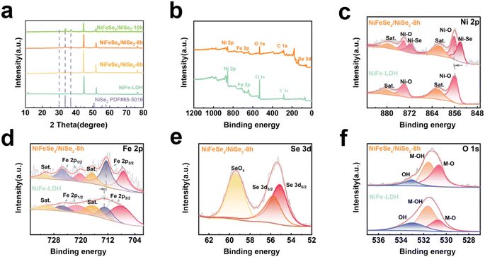
XRD was used to characterize the phases of NiFe-LDH, NiFeSe4/NiSe2-6 h, NiFeSe4/NiSe2-8 h, and NiFeSe4/NiSe2-10 h, which confirmed that the selenized materials were made of NiFeSe4 and NiSe2. For these materials, there were three obvious peaks at 2θ = 44.605°, 51.979°, and 76.690°. These three peaks were related to the NF base used. These three peaks matched NF (PDF # 70-0989) (Fig. S3a†) and corresponded to the (111), (200) and (220) crystal planes, respectively. For the material prepared by the hydrothermal method, its spectrum matched well with NiFe-LDH (PDF # 40-0215) (Fig. S3a†). The results demonstrated that NiFe-LDH could be successfully synthesized using the hydrothermal technique. Comparing the spectrum of the material after selenization with NiFe-LDH, it was found that the NiFe-LDH peak disappeared, proving that the composition of the material changed after selenization. Analysis of the selenized materials revealed that 2θ = 30.040°, 33.660° and 36.980° match the (200), (210) and (211) crystal planes of NiSe2 (PDF # 65-5016). It was also found from Fig. 4a that the diffraction related to NiSe2 gradually increased as the reaction time increased, which indicated that the crystallinity of the NiSe2 material further increased. Some peaks of the NiFeSe4/NiSe2-6 h, NiFeSe4/NiSe2-8 h, and NiFeSe4/NiSe2-10 h materials corresponded to NiFeSe4 (PDF # 97-063-2969), which indicated that the selenized material also contained NiFeSe4 (Fig. S3b†). NiSe2 and NiFeSe4 had similar lattice structures (Fig. S4†), and the difference between them was the atoms at the vertices. The atoms at the vertex of NiSe2 were all Ni atoms, while the atoms at the vertex of NiFeSe4 were Ni atoms and Fe atoms, and they occupied 1/2 of the positions of the vertex. Since Fe atoms have a smaller atomic radius than Ni atoms, this may cause the diffraction peak of NiFeSe4 to move to a position larger than 2θ compared to the diffraction peak of NiSe2. From this, the content of Fe element in the material was relatively low relative to other elements. Therefore, the ratio of Ni to Fe elements in the NiFeSe4 material formed by selenization may not be the original 1![[thin space (1/6-em)]](https://www.rsc.org/images/entities/char_2009.gif) :
:![[thin space (1/6-em)]](https://www.rsc.org/images/entities/char_2009.gif) 1 ratio, and the ratio may be greater than 1. Therefore, the diffraction peak of NiFeSe4 was shifted.
1 ratio, and the ratio may be greater than 1. Therefore, the diffraction peak of NiFeSe4 was shifted.
XPS was used to analyze the elements and valence states of the materials. It can be obtained from the full spectra of NiFe-LDH and NiFeSe4/NiSe2-8 h (Fig. 4b) that both materials contain Ni and Fe elements, but compared with NiFe-LDH, NiFeSe4/NiSe2-8 h also contains Se element. This corresponded to the previous mapping, further proving that the selenized material contained Se element. Fig. 4c–f show the high-resolution XPS spectra of Ni 2p, Fe 2p, Se 3d and O1s of NiFeSe4/NiSe2-8 h, respectively. Fig. 4c shows the Ni 2p spectra of the NiFeSe4/NiSe2-8 h material and NiFe-LDH, which were fitted. Among them, the fitting peak of 856.1 5 eV corresponded to Ni 2p3/2 of the NiFeSe4/NiSe2-8 h material.12 Compared with Ni 2p3/2 (855.85 eV) of the NiFe-LDH material,40 it was found that the selenized material migrated towards a higher binding energy. This phenomenon indicates that the material may have a higher valence state, which also implies that NiFeSe4/NiSe2-8 h may have a higher catalytic activity.41 The peaks at 874.01 eV and 873.67 eV correspond to Ni 2p1/2 of the NiFeSe4/NiSe2-8 h material and NiFe-LDH material, respectively.40 For NiFe-LDH, the other two fitted peaks correspond to satellite peaks. It was possible to see that the selenified material had two more peaks beneath its spectra than NiFe-LDH when comparing the spectra of NiFeSe4/NiSe2-8 h and NiFe-LDH. The two peaks at 854.0 and 871.62 eV indicated the formation of Ni–Se bonds in the selenized material,41 further proving that Se elements were present in the selenized material. The presence of Ni–Se bonds also corresponded to the results of XRD analysis, that was, NiSe2 existed in the selenized material. The Fe 2p spectrum is depicted in Fig. 4d. The Fe 2p spectral analysis revealed that the fitting peaks at 707.28 eV and 712.45 eV correspond to Fe 2p3/2, while the fitting peaks at 720.28 eV and 725.58 eV correspond to Fe 2p1/2.12,42 Simultaneously, the two fitting peaks at 716.68 eV and 730.58 eV correspond to two satellite peaks.12,42 Among them, the Fe3+ peak of Fe 2p3/2 in NiFeSe4/NiSe2-8 h was shifted to a position with lower binding energy compared with NiFe-LDH (712.63 eV). This was due to the addition of greater electronegativity to the substance.12 The Se atoms made the adjacent Fe atoms of the NiFeSe4/NiSe2-8 h catalyst rich in electrons. The Se 3d spectrum of NiFeSe4/NiSe2-8 h is depicted in Fig. 4e, with the peak at 55.11 eV representing Se 3d5/2 and the peak at 59.39 eV indicating Se 3d3/2.41,43 The presence of the peak at 59.39 eV was ascribed to the oxidation peak resulting from the oxidation of the Se surface, which corresponds to the Se–O bond.41,43 Furthermore, the O 1s spectrum of the material was fitted to three peaks, which corresponded to water molecules that were adsorbed in a physical manner, M–OH bonds that were adsorbed chemically, and M–O bonds that were adsorbed chemically.40,41 In conclusion, the Ni and Fe peaks in NiFeSe4/NiSe2-8 h and NiFe-LDH were compared, and it was found that the peaks were shifted. This suggested that there may be a re-distribution of electrons in the material after selenization, and this distribution may promote the electrocatalytic properties of the material.
Electrochemical OER performance
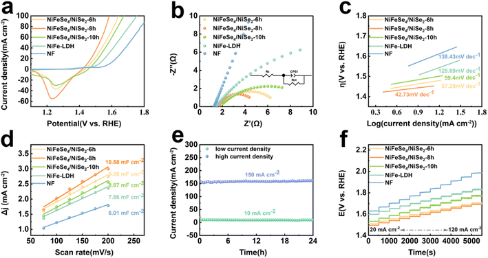
The OER properties of the NF, NiFe-LDH, NiFeSe4/NiSe2-6 h, NiFeSe4/NiSe2-8 h and NiFeSe4/NiSe2-10 h materials were tested. It was clear from Fig. S7a† that the LSV curves in the positive scan showed a marked oxidation peak at approximately 1.4 V, which was likely due to the conversion of Ni2+ to Ni3+. The oxidation peak area of NiFeSe4/NiSe2-8 h was larger than that of NiFeSe4/NiSe2-6 h and NiFeSe4/NiSe2-10 h, suggesting that NiFeSe4/NiSe2-8 h produced more active sites.12 The material's performance was assessed by employing backsweep LSV in order to mitigate the impact of the oxidation peaks. Fig. 5a shows the LSV curves of all materials. The NiFeSe4/NiSe2-8 h material prepared with a selenization time of 8 h had excellent OER electrocatalytic activity. When the overpotential was 218 mV, the OER reaction can take place at 10 mA cm−2 current density, which was lower than NF (355 mV), NiFe-LDH (291 mV), NiFeSe4/NiSe2-6 h (237 mV) and NiFeSe4/NiSe2-10 h (258 mV).The charge transfer between the material and the electrolyte was studied using EIS, and the interfacial dynamics of the OER reaction were further investigated. The Nyquist curves of NF, NiFe-LDH, NiFeSe4/NiSe2-6 h, NiFeSe4/NiSe2-8 h and NiFeSe4/NiSe2-10 h are depicted in Fig. 5b. The obtained curves were calculated according to the equivalent circuit model (Fig. S5†) for fitting. The impedance plot without equivalent circuit fitting is shown in Fig. S10a.†Fig. 5b indicates that the NiFeSe4/NiSe2-8 h half-circles are smaller than those of the other samples, indicating that NiFeSe4/NiSe2-8 h had the least amount of charge transfer resistance and the most conductivity. The data in Table S2† indicate that NiFeSe4/NiSe2-8 h had a reduced charge transfer resistance and a high charge transfer capacity. The NiFeSe4/NiSe2-8 h heterojunction structure reduced the Rct values, improved the electron transfer rate and improved the OER performance. The ohmic resistance of NiFeSe4/NiSe2-8 h was 3.279 Ω, indicating that NiFeSe4/NiSe2-8 h was in good contact with the electrolyte and had minimal resistance to the electrolyte. The LSV results in Fig. 5c indicate that NF (138.43 mV dec−1), NiFe-LDH (125.69 mV dec−1), NiFeSe4/NiSe2-6 h (57.29 mV dec−1), NiFeSe4/NiSe2-10 h (59.4 mV dec−1), and NiFeSe4/NiSe2-8 h (42.73 mV dec−1) were the phases with the lowest Tafel slope, which significantly improved the OER activity and kinetics. The lower the Tafel slope, the quicker the catalyst's speed and the more effective the substance's catalytic activity, which was in agreement with the Nyquist curves' findings. Simultaneously, the Tafel slope indicated data regarding the catalytic process. The OER reaction was a four-electron transfer process, which sequentially formed the intermediates OH*, O*, and OOH*. When the Tafel slope was between 40 and 60 mV dec−1, it indicated that the limiting pace of the material was the formation of O–O bonds (OOH*).44 The Tafel slope of NiFeSe4/NiSe2-8 h lay in this interval, so the rate limiting step of this material was the formation of OOH*. The Cdl of the material was then studied using CV repeated cycle tests. Fig. S6† shows the CV scan images of different materials. Fig. 5d shows that the Cdl values of NF, NiFe-LDH, NiFeSe4/NiSe2-6 h, NiFeSe4/NiSe2-8 h and NiFeSe4/NiSe2-10 h were 6.01, 7.86, 9.06, 10.58 and 8.87 mF cm−2, respectively. Compared with the other materials, NiFeSe4/NiSe2-8 h had a larger electrochemically active area. The LSV curves were normalized using the ESCA, and Fig. S7b† shows the normalized data. As can be seen from Fig. S7b,† NiFeSe4/NiSe2-8 h still had excellent performance in the normalized LSV curves.
The material stability of the OER catalysts was also taken into consideration when assessing their performance, in addition to their good OER capabilities. The stability test of NiFeSe4/NiSe2-8 h at 10 mA cm−2 and 100 mA cm−2 is demonstrated in Fig. 5e. From the fact that there was no obvious downward trend in the curve in the figure, it was concluded that NiFeSe4/NiSe2-8 h had good stability. The surface shape of the NiFeSe4/NiSe2-8 h material did not change considerably after 24 h of stability testing, as shown in Fig. S7d.† The LSV test of NiFeSe4/NiSe2-8 h following the stability test was compared to the LSV test conducted before the test (Fig. S7c†). The LSV curve after the stability test and the curve before the test were basically consistent, indicating that the material had good OER stability. The NF, NiFe-LDH, NiFeSe4/NiSe2-6 h, NiFeSe4/NiSe2-8 h and NiFeSe4/NiSe2-10 h working electrodes were tested at various current densities (ranging from 20 mA cm−2 to 120 mA cm−2, increasing by 10 mA cm−2) at 500 second intervals. NiFeSe4/NiSe2-8 h had the lowest initial voltage compared to the other materials, and yielded similar outcomes regardless of the current density. In the experiment, NiFeSe4/NiSe2-8 h exhibited impressive catalytic activity and demonstrated satisfactory performance and steadiness when subjected to multi-level progressive current density.
Electrochemical HER performance
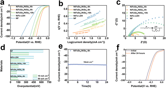
Then, the HER performance of NF, NiFe-LDH, NiFeSe4/NiSe2-6 h, NiFeSe4/NiSe2-8 h and NiFeSe4/NiSe2-10 h was tested. The LSV curves (Fig. 6a) demonstrated that NiFeSe4/NiSe2-8 h (121 mV) had an overpotential of 10 mA cm−2 current density. When compared to NiFe-LDH (279 mV), NiFeSe4/NiSe2-6 h (141 mV), and NiFeSe4/NiSe2-10 h (157 mV), the overpotential of NiFeSe4/NiSe2-8 h was small. The Tafel slope was calculated from the LSV curves of the different materials (Fig. 6b). Fig. 6d shows the HER performance of each material in greater detail. The Tafel slope of NiFeSe4/NiSe2-8 h (197.42 mV dec−1) was lower than that of NF (469.32 mV dec−1), NiFe-LDH (366.5 mV dec−1), NiFeSe4/NiSe2-6 h (264.72 mV dec−1) and NiFeSe4/NiSe2-10 h (355.88 mV dec−1) among the other compounds. Subsequently, the Nyquist curves of the various materials were evaluated. The equivalent circuit (Fig. S5†) was used for fitting. The impedance plot without equivalent circuit fitting is shown in Fig. S10b.† The Nyquist curve (Fig. 5c) indicated that NiFeSe4/NiSe2-8 h had the tiniest semicircle. The Nyquist curve depicted a semicircle, which symbolizes the resistance to Rct between the electrode and the electrolyte.45 Therefore, the smallest semicircle indicated that NiFeSe4/NiSe2-8 h had the lowest Rct value, indicating that its charge transfer kinetics and conductivity were the fastest. In addition, the stability test of NiFeSe4/NiSe2-8 h was conducted for 24 h. Fig. 6e shows that the performance of NiFeSe4/NiSe2-8 h had not changed significantly. Fig. 6f indicates that the material parameters before and after the stability test vary very little. Fig. S8† shows images from the SEM of the material, which indicated that the shape of the material did not change considerably following the stability test. It was proved that the material had good stability, corresponding to the results obtained in Fig. 6e.Overall water splitting performance
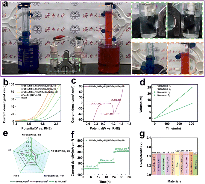
The NiFeSe4/NiSe2-8 h catalyst electrode demonstrated impressive catalytic performance in both OER and HER experiments. Consequently, we conducted a double-electrode alkaline water splitting experiment with the catalyst that had been prepared as a functional electrode. Fig. 7a depicts a mechanism for the water splitting and collection of gas. When the cell's voltage was applied at both ends, a huge volume of H2 and O2 gas was created near the cathode and anode, respectively. The volume ratio of H2 and O2 produced can be determined by gathering the gas produced and comparing it with the theoretical volume ratio of H2 and O2 generated through overall water splitting (2![[thin space (1/6-em)]](https://www.rsc.org/images/entities/char_2009.gif) :
:![[thin space (1/6-em)]](https://www.rsc.org/images/entities/char_2009.gif) 1). As can be seen from the data in Fig. 7d, the amount collected was close to that expected, indicating that the NiFeSe4/NiSe2-8 h catalyst did react.
1). As can be seen from the data in Fig. 7d, the amount collected was close to that expected, indicating that the NiFeSe4/NiSe2-8 h catalyst did react.
The electrocatalytic properties of the different catalytic electrodes are shown in Fig. 7b. It was evident that the NiFeSe4/NiSe2-8 h‖NiFeSe4/NiSe2-8 h catalytic electrode ratio demonstrated superior electrolytic water splitting capability compared to NiFeSe4/NiSe2-6 h‖NiFeSe4/NiSe2-6 h, NiFeSe4/NiSe2-10 h‖NiFeSe4/NiSe2-10 h, NiFe-LDH‖NiFe-LDH and NF‖NF. NiFeSe4/NiSe2-8 h‖NiFeSe4/NiSe2-8 h performed water splitting at 1.572 V with a 10 mA cm−2 current density. Simultaneously, the LSV curves of various materials at high current densities were examined (Fig. S9a†), and NiFeSe4/NiSe2-8 h and the other materials created through selenization must attain the same current density at high current densities. The voltage continued to be at its minimum. The overall water splitting performance of each material is depicted in a more accessible manner in Fig. 7e. The three-electrode system test in the alkaline electrolyte test revealed that NiFeSe4/NiSe2-8 h had HER and OER overpotentials of −121 mV and 1448 mV relative to RHE when the current density was 10 mA cm−2, thus indicating a correlation between the OER and HER of 1.568 V and RHE voltage difference (Fig. 7c).
The catalytic efficiency surpassed all others. Subsequently, the durability of the constructed NiFeSe4/NiSe2-8 h‖NiFeSe4/NiSe2-8 h was examined. The NiFeSe4/NiSe2-8 h catalytic electrode in Fig. 7f exhibited robust and long-lasting catalytic stability, with no noticeable decrease in performance after 36 h of uninterrupted operation at room temperature (current densities of 10, 100 and 300 mA cm−2, respectively, operating at each current density for 12 h). The electrolysis of water was conducted in an industrial setting with a high current density (>200 mA cm−2, high current density HCD), thus making the stability of the catalyst under HCD a critical factor, and the NiFeSe4/NiSe2-8 h catalytic electrode exhibited excellent stability at 300 mA cm−2.46,47 Fig. S9b† shows that the LSV curve of the material before the stability test shows almost no different from that after the test, which proved that the material has excellent stability. This conclusion echoes previous conclusions reached for the OER and HER. A comparison was made between the two-electrode electrolytic cell composed of NiFeSe4/NiSe2-8 h and the electrolytic cell composed of other catalysts at a current density of 10 mA cm−2. The NiFeSe4/NiSe2-8 h necessitated a lower voltage than the one previously reported (Fig. 7g), demonstrating its remarkable catalytic capability.
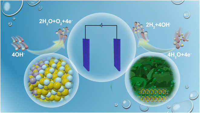
Excellent overall water splitting performance was present in NiFeSe4/NiSe2-8 h. A schematic diagram of the NiFeSe4/NiSe2-8 h cathode and anode utilized in the electrolytic cell to carry out a water splitting reaction is shown in Fig. 8. First, the NiFeSe4/NiSe2 heterostructure was successfully prepared using an in situ growth method on a three-dimensional porous foam substrate, avoiding electron transfer obstacles caused by the use of adhesives and improving the interaction between the material and the substrate. Second, selenization changed the initial crystal structure of the material and promoted the movement of electrons in the material in a direction that promoted the material properties. The redistribution of electrons meant changes in the valence state of the atoms in the material, and this change would promote the improvement of the material properties. Finally, selenization to form a NiFeSe4/NiSe2 heterostructure not only promoted the redistribution of electrons within the material, but also provided a larger active area, which was also of great help in promoting the catalytic performance of the material.
Conclusions
In conclusion, in situ growth was used to create NiFeSe4/NiSe2-8 h catalytic materials. The characterization analysis showed that we effectively developed a catalytic material with a NiFeSe4/NiSe2-8 h heterojunction structure. By altering the selenization time, a heterojunction structure with NiSe2 uniformly formed on the surface of NiFeSe4 was produced, with 8 h being the optimal time. To achieve the minimum reaction current density of 10 mA cm−2 in an alkaline electrolyte, the required overpotentials for NiFeSe4/NiSe2-8 h were 218 mV (OER) and 121 mV (HER), respectively. The catalytic activity of the material was enhanced due to the formation of the heterojunction structure after selenization, as well as the redistribution of electrons within the material after selenization. In heterostructures, the development of internal electric fields facilitated the redistribution of electrons. The XPS analysis revealed that the Ni and Fe peaks had shifted, suggesting that the electrons in the vicinity had altered. Furthermore, the performance of NiFeSe4/NiSe2-8 h remained largely unchanged even after undergoing continuous HER and OER reactions at a current density of 10 mA cm−2 for 24 h and OER at a current density of approximately 150 mA cm−2 for 24 h. Additionally, NiFeSe4/NiSe2-8 h was employed as the cathode and anode of the two-electrode electrolyzer, and the performance of continuous operation for 36 h at various current densities showed minimal decline, which was a crucial factor in practical applications. This research showed that by using an in situ growth technique to build heterostructure materials, the catalytic performance of these materials was improved, making it a viable option for the production of cost-effective, efficient, and reliable bifunctional catalysts.Conflicts of interest
The authors declare that they have no known competing financial interests or personal relationships that could have appeared to influence the work reported in this paper.Acknowledgements
This work was supported by the National Natural Science Foundation of China (No. 51802177), Joint Funds of the National Natural Science Foundation of China (No. U22A20140), and Project supported by State Key Laboratory of Powder Metallurgy, Central South University, Changsha, China. All the authors contributed to the preparation, characterization and analysis of the structure and performance of the materials. All the authors discussed the results and commented on the manuscript.References
- Y. Yang, Y. Kang, H. Zhao, X. Dai, M. Cui, X. Luan, X. Zhang, F. Nie, Z. Ren and W. Song, Small, 2020, 16, 1905083 CrossRef CAS PubMed.
- S. Ni, H. Qu, Z. Xu, X. Zhu, H. Xing, L. Wang, J. Yu, H. Liu, C. Chen and L. Yang, Appl. Catal., B, 2021, 299, 120638 CrossRef CAS.
- Y. Du, B. Li, G. Xu and L. Wang, InfoMat, 2023, 5, e12377 CrossRef CAS.
- Y. Huang, L.-W. Jiang, H. Liu and J.-J. Wang, Chem. Eng. J., 2022, 441, 136121 CrossRef CAS.
- L. Chen, Y. Wang, X. Zhao, Y. Wang, Q. Li, Q. Wang, Y. Tang and Y. Lei, J. Mater. Sci. Technol., 2022, 110, 128–135 CrossRef CAS.
- X.-P. Li, L.-R. Zheng, S.-J. Liu, T. Ouyang, S. Ye and Z.-Q. Liu, Chin. Chem. Lett., 2022, 33, 4761–4765 CrossRef CAS.
- P. Wang, Y. Luo, G. Zhang, Z. Chen, H. Ranganathan, S. Sun and Z. Shi, Nano-Micro Lett., 2022, 14, 120 CrossRef CAS PubMed.
- A. Ali, F. Long and P. K. Shen, Electrochem. Energy Rev., 2022, 5, 1 CrossRef CAS.
- H. Liu, J. Gao, X. Xu, Q. Jia, L. Yang, S. Wang and D. Cao, Chem. Eng. J., 2022, 448, 137706 CrossRef CAS.
- K. Li, D. Feng and Y. Tong, ChemSusChem, 2022, 15, e202200590 CrossRef CAS PubMed.
- X. Guo, M. Li, L. Qiu, F. Tian, L. He, S. Geng, Y. Liu, Y. Song, W. Yang and Y. Yu, Chem. Eng. J., 2023, 453, 139796 CrossRef CAS.
- L. Tan, J. Yu, C. Wang, H. Wang, X. Liu, H. Gao, L. Xin, D. Liu, W. Hou and T. Zhan, Adv. Funct. Mater., 2022, 32, 2200951 CrossRef CAS.
- S. M. N. Jeghan, D. Kim, Y. Lee, M. Kim and G. Lee, Appl. Catal., B, 2022, 308, 121221 CrossRef CAS.
- H. Qi, P. Zhang, H. Wang, Y. Cui, X. Liu, X. She, Y. Wen and T. Zhan, J. Colloid Interface Sci., 2021, 599, 370–380 CrossRef CAS PubMed.
- A. Fauzi, S. Geng, F. Tian, Y. Liu, H. Li, Y. Yu, J. Li and W. Yang, Int. J. Hydrogen Energy, 2023, 48, 1370–1379 CrossRef CAS.
- D. Wang, Y. Chen, L. Fan, T. Xiao, T. Meng, Z. Xing and X. Yang, Appl. Catal., B, 2022, 305, 121081 CrossRef CAS.
- Y. Wu, Y. Li, M. Yuan, H. Hao, X. San, Z. Lv, L. Xu and B. Wei, Chem. Eng. J., 2022, 427, 131944 CrossRef CAS.
- H. Jing, P. Zhu, X. Zheng, Z. Zhang, D. Wang and Y. Li, Adv. Powder Technol., 2022, 1, 100013 Search PubMed.
- Z. Li, X. Wu, X. Jiang, B. Shen, Z. Teng, D. Sun, G. Fu and Y. Tang, Adv. Powder Technol., 2022, 1, 100020 Search PubMed.
- K. Sun, Y. Zhao, J. Yin, J. Jin, H. Liu and P. Xi, Acta Phys.-Chim. Sin., 2022, 38, 2107005 Search PubMed.
- A. Li, L. Zhang, F. Wang, L. Zhang, L. Li, H. Chen and Z. Wei, Appl. Catal., B, 2022, 310, 121353 CrossRef CAS.
- Y. Dong, Z. Deng, Z. Xu, G. Liu and X. Wang, Small Methods, 2023, 2300071 CrossRef CAS PubMed.
- X. Zheng, X. Han, Y. Cao, Y. Zhang, D. Nordlund, J. Wang, S. Chou, H. Liu, L. Li and C. Zhong, Adv. Mater., 2020, 32, 2000607 CrossRef CAS PubMed.
- M. Yu, J. Zheng and M. Guo, J. Energy Chem., 2022, 70, 472–479 CrossRef CAS.
- Y. Liao, R. He, W. Pan, Y. Li, Y. Wang, J. Li and Y. Li, Chem. Eng. J., 2023, 464, 142669 CrossRef CAS.
- N. S. Gultom, H. Abdullah, C.-N. Hsu and D.-H. Kuo, Chem. Eng. J., 2021, 419, 129608 CrossRef CAS.
- M. Singh, T. T. Nguyen, J. Balamurugan, N. H. Kim and J. H. Lee, Chem. Eng. J., 2022, 430, 132888 CrossRef CAS.
- J. Song, Y. Chen, H. Huang, J. Wang, S. C. Huang, Y. F. Liao, A. E. Fetohi, F. Hu, H. y. Chen and L. Li, Adv. Sci., 2022, 9, 2104522 CrossRef CAS PubMed.
- Y. Huang, L.-W. Jiang, X.-L. Liu, T. Tan, H. Liu and J.-J. Wang, Appl. Catal., B, 2021, 299, 120678 CrossRef CAS.
- J. Wang, D. T. Tran, K. Chang, S. Prabhakaran, D. H. Kim, N. H. Kim and J. H. Lee, Energy Environ. Mater., 2023, 6, e12526 CrossRef CAS.
- J. Balamurugan, T. T. Nguyen, D. H. Kim, N. H. Kim and J. H. Lee, Appl. Catal., B, 2021, 286, 119909 CrossRef CAS.
- Q. Wang, R. He, F. Yang, X. Tian, H. Sui and L. Feng, Chem. Eng. J., 2023, 456, 141056 CrossRef CAS.
- S.-Q. Chang, C.-C. Cheng, P.-Y. Cheng, C.-L. Huang and S.-Y. Lu, Chem. Eng. J., 2022, 446, 137452 CrossRef CAS.
- A. Sun, Y. Qiu, X. Zheng, L. Cui and J. Liu, J. Colloid Interface Sci., 2023, 632, 108–116 CrossRef CAS PubMed.
- L. Tan, J. Yu, H. Wang, H. Gao, X. Liu, L. Wang, X. She and T. Zhan, Appl. Catal., B, 2022, 303, 120915 CrossRef CAS.
- B. Zhang, J. Shan, W. Wang, P. Tsiakaras and Y. Li, Small, 2022, 18, 2106012 CrossRef CAS PubMed.
- T. Yu, Q. Xu, L. Luo, C. Liu and S. Yin, Chem. Eng. J., 2022, 430, 133117 CrossRef CAS.
- Z. Li, M. Hu, P. Wang, J. Liu, J. Yao and C. Li, Coord. Chem. Rev., 2021, 439, 213953 CrossRef CAS.
- H. Zhang, A. W. Maijenburg, X. Li, S. L. Schweizer and R. B. Wehrspohn, Adv. Funct. Mater., 2020, 30, 2003261 CrossRef CAS.
- Q. Wen, K. Yang, D. Huang, G. Cheng, X. Ai, Y. Liu, J. Fang, H. Li, L. Yu and T. Zhai, Adv. Energy Mater., 2021, 11, 2102353 CrossRef CAS.
- C. Liu, Y. Han, L. Yao, L. Liang, J. He, Q. Hao, J. Zhang, Y. Li and H. Liu, Small, 2021, 17, 2007334 CrossRef CAS PubMed.
- J. Liu, S. Xiao, X. Li, Z. Li, X. Li, W. Zhang, Y. Xiang, X. Niu and J. S. Chen, Chem. Eng. J., 2021, 417, 129279 CrossRef CAS.
- J. Hu, Y. Q. Liang, S. L. Wu, Z. Y. Li, C. S. Shi, S. Y. Luo, H. J. Sun, S. L. Zhu and Z. D. Cui, Mater. Today Nano, 2022, 17, 100150 CrossRef CAS.
- J. Li, D. Chu, H. Dong, D. R. Baker and R. Jiang, J. Am. Chem. Soc., 2019, 142, 50–54 CrossRef PubMed.
- J.-Y. Xue, F.-L. Li, B. Chen, H. Geng, W. Zhang, W.-Y. Xu, H. Gu, P. Braunstein and J.-P. Lang, Appl. Catal., B, 2022, 312, 121434 CrossRef CAS.
- Y. Luo, Z. Zhang, M. Chhowalla and B. Liu, Adv. Mater., 2022, 34, 2108133 CrossRef CAS PubMed.
- S. Qiu, B. Zhang, X. Wang, J. Huang, G. Zhao, M. Ding and X. Xu, J. Colloid Interface Sci., 2023, 641, 277–288 CrossRef CAS PubMed.
Footnote |
| † Electronic supplementary information (ESI) available. See DOI: https://doi.org/10.1039/d3ta06701g |
| This journal is © The Royal Society of Chemistry 2024 |

