 Open Access Article
Interfacial design towards stable zinc metal-free zinc-ion batteries with high energy density†
Ting
Xiong‡
a,
Deqiang
Zhang‡
abc,
Jing Ying
Yeo
bc,
Yufeng
Zhan
b,
Yong Kang
Ong
 c,
Carlos Maria
Alava Limpo
b,
Lu
Shi
b,
Yifan
Rao
b,
Yanhui
Pu
b,
Wenhui
Lai
b,
Jonghak
Lee
c,
Wee Siang
Vincent Lee
b and
Barbaros
Özyilmaz
c,
Carlos Maria
Alava Limpo
b,
Lu
Shi
b,
Yifan
Rao
b,
Yanhui
Pu
b,
Wenhui
Lai
b,
Jonghak
Lee
c,
Wee Siang
Vincent Lee
b and
Barbaros
Özyilmaz
 *abc
*abc
aDepartment of Physics, National University of Singapore, Singapore. E-mail: barbaros@nus.edu.sg
bDepartment of Materials Science and Engineering, National University of Singapore, Singapore, Singapore
cCentre for Advanced 2D Materials, National University of Singapore, Singapore
First published on 2nd February 2024
Abstract
Zinc metal-free zinc-ion batteries hold promise for achieving higher energy densities by eliminating the need for dense zinc foil as the anode. However, the direct use of substrates like copper foil in these batteries results in poor cyclic stability due to dendrite growth. Herein, we propose a strategy to modulate the nucleation sites and growth dynamics of Zn. This is achieved by introducing a graphene coating on the copper substrate, which directs the initial nucleation of Zn to form hexagonal plates. Subsequently, the incorporation of positively polarized poly(vinylidene fluoride-trifluoroethylene) promotes growth along these hexagonal plates, resulting in uniform crystalline plates. As a result, the half-cell demonstrated a significant improvement in the cyclic life of 3000 cycles at a high current density of 10 mA cm−2 and capacity of 1 mA h cm−2. When paired with Zn-inserted MnO2 cathode, the full cell exhibited high cyclic stability (retaining 83% capacity after 500 cycles at 1 mA cm−2) and energy density of 378 W h kg−1 at 0.5 mA cm−2. This is notably higher than the conventional Zn ion battery based on a Zn anode (136 W h kg−1). To showcase its potential, we prepared a pouch cell that successfully powered the electric fan and LED lights, suggesting its promising application in high-performance Zn ion batteries.
Introduction
Batteries are a cornerstone of modern life that fuel our daily activities, drive technological advancement, and promote sustainable energy practices and catalytic processes across a plethora of domains.1–3 As such, the demand for batteries with high energy density has grown notably in recent years. To meet such demands, anode-less batteries have emerged as a promising battery technology that could offer enhanced energy densities.4,5 The uniqueness of these anode-less metal battery technologies lies in structure design, where non-active elements like copper (Cu) foil are used to substitute anode materials such as lithium (Li), sodium (Na), or zinc (Zn) that are conventionally used in the battery technologies.6–8 Hence, due to this innovative architecture, both the battery volume and mass could be significantly reduced, and this would consequently lead to an elevated energy density.Within the realm of anode-less batteries, aqueous Zn metal-free Zn ion batteries (AZMZIBs) have garnered significant attention. This is primarily attributed to the high natural abundancy of zinc, widespread availability, and cost-effectiveness when compared to other battery materials.9,10 Nonetheless, without a fresh Zn metal reservoir for replenishment during cycling, battery performance becomes critically dependent on coulombic efficiency and dendrite formation.11–13 According to the studies, zinc deposition has greater affinity to the lower surface energy sites, which unfortunately leads to the emergence of needle-like dendritic structures after repeated cycling. Even though various strategies, such as surface modification and electrolyte regulation, have been proposed to curb the growth of Zn dendrites, achieving optimal cycle stability (which is a prerequisite for practical applications) remains elusive.14–16 A major bottleneck for those strategies is the inefficient regulation of Zn nucleation sites and their growth dynamics, which requires the presence of uniform nucleation sites to dictate the Zn nucleation process. For instance, graphene can serve as a suitable substrate for Zn nucleation due to its unique two-dimensional lattice. Since both graphene and Zn possess hexagonal lattice structures with a minimal lattice mismatch of approximately 8%, this would ensure good compatibility.17 After realizing uniform nucleation by providing suitable nucleation sites, the subsequent step would be to ensure homogeneous growth to curb dendrite formation. Notably, ferroelectric materials such as β-phase poly(vinylidene fluoride-trifluoroethylene) (P(VDF-TrFE)) exhibit intrinsic electric polarization that can be modulated or even reversed when exposed to an external electric field. Consequently, this could potentially offer a method to regulate Zn deposition and the flow of Zn2+ ions.18 To investigate the influence of P(VDF-TrFE) coatings on copper substrates, we performed simulation studies on the electrostatic field distributions on the surface of the material. According to the preliminary results, Zn2+ ions are more uniformly distributed around the Zn plate after coated with positively polarized P(VDF-TrFE), which ultimately leads to a more even and horizontal deposition when compared to those under negative or non-polarized conditions. Such findings may underscore the potential of using positively polarized P(VDF-TrFE) as an effective tool to control the Zn growth dynamics and circumvent dendrite formation.
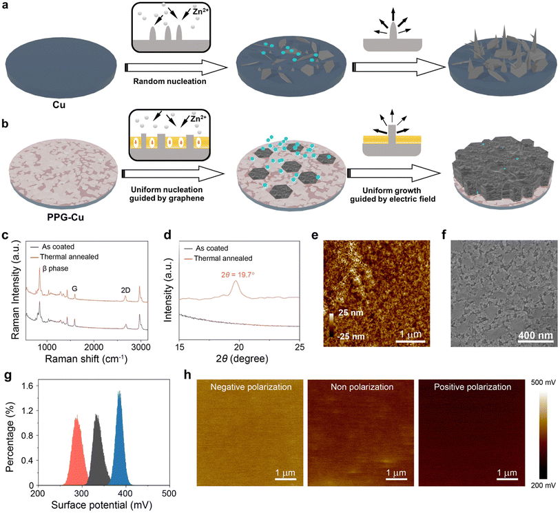
Herein, we report a facile strategy that involves using positively polarized P(VDF-TrFE) and graphene to enhance the Zn deposition compatibility of Cu foil, denoted as PPG-Cu. Such a strategy is essential as standard Cu foils can easily facilitate the growth of Zn dendrites, which inevitably leads to battery failure (as shown in Fig. 1a). In contrast, the PPG-Cu ensures a uniform deposition of Zn, whereby the graphene coating plays a pivotal role in directing the initial Zn nucleation to form hexagonal plates. After which, the positively polarized P(VDF-TrFE) helps to supress the Zn dendrite growth by realizing uniform and lateral Zn deposition (depicted in Fig. 1b). Owing to these enhancements, the half-cell test based on PPG-Cu demonstrated superior cyclic longevity and remarkable coulombic efficiency. The half-cell was able to cycle for a commendable 3000 times under 10 mA cm−2 and a capacity of 1 mA h cm−2, whereas the standard Cu cell ceased functioning after just 20 hours under similar conditions. More impressively, the half-cell could last for over 200 hours at a higher capacity of 5 mA h cm−2, while maintaining a smooth surface morphology – a stark contrast to the dendrite-dense morphology observed in the standard Cu cell. Furthermore, when combined with Zn-inserted MnO2 cathode, the PPG-Cu foil-based full cell exhibited a specific capacity of 270 mA h g−1 at 0.5 mA cm−2 and 75 mA h g−1 at 5 mA cm−2, with a good capacity retention of 83% after 500 cycles at 1 mA cm−2. Remarkably, in the absence of conventional Zn anode, the energy density of the full cell soared to 378 W h kg−1, significantly outperforming the conventional Zn ion batteries equipped with Zn anodes (136 W h kg−1). Such findings underscore the potential of our proposed strategy in pioneering the next generation high-energy batteries, that could combine high energy density with extended operational lifespans.
Results and discussion
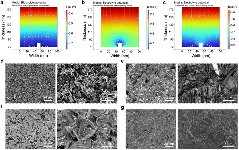
Graphene@Cu was selected as the substrate for modification for Zn metal-free Zn ion batteries. From the X-ray diffraction (XRD) data and scanning electron microscopy (SEM) results, the purchased graphene@Cu was confirmed to be of high quality without defects (Fig. S1†). Subsequently, P(VDF-TrFE) polymer was mixed with zinc trifluoromethane sulfonate salt and the mixture was subsequently used as the coating material for graphene@Cu substrate. Zinc trifluoromethane sulfonate was added as these salt particles dissolve readily in aqueous electrolytes to form porous structures so as to establish adequate zinc-ion diffusion channels. The as-prepared solution was uniformly coated onto graphene@Cu (see Experimental section) via spin-coating, which was then followed with a thermal annealing process to convert P(VDF-TrFE) into ferroelectric β phase. As shown by the Raman spectra in Fig. 1c, two distinctive peaks were observed at 1594 cm−1 and 2671 cm−1.19,20 These two peaks correspond to the G band and 2D band of graphene, respectively, suggesting that the graphene remained undamaged during the annealing process. Additionally, a dominant peak at approximately 845 cm−1 (attributed to the β-phase of P(VDF-TrFE)) emerged after thermal annealing.21 This is further confirmed by the presence of β-phase peak (2θ ≈ 19.7°) of P(VDF-TrFE) after thermal annealing in the XRD results (Fig. 1d).22 Since P(VDF-TrFE) itself is not conductive, the thickness of the P(VDF-TrFE) coating layer was controlled to around 50 nm, as revealed by atomic force microscopy (AFM) (Fig. 1e), to ensure good zinc ions conductivity. Also, the crystalized P(VDF-TrFE) β-phase possessed numerous grains morphology (Fig. 1f). Next, the Corona poling technique was adopted to polarize the P(VDF-TrFE) film. As indicated by the Kelvin probe force microscopy (KPFM), the measured surface potentials of the negatively polarized, nonpolarized, and positively polarized P(VDF-TrFE) samples were determined to be about 385 mV, 332 mV, and 283 mV, respectively (Fig. 1g and h). It is worth noting that the polarization process did not trigger visible alterations to the grains morphology as revealed by the SEM images in Fig. S2.† When compared to the nonpolarized state, the polarization process can effectively alter the orientation of dipoles in the ferroelectric polymer, which could lead to either an increase or decrease in the surface potential in response to the applied external electric field.Based on the various surface potential situations, finite element simulations were performed on the electrostatic field distributions and electrochemical potential distribution using P(VDF-TrFE) with different polarizations. Fig. 2a shows the simulated Zn2+ distribution of P(VDF-TrFE)-coated graphene@Cu foil without polarization. Due to the electric field lines pointing towards the negative electrode, the strong uniform electric field emitted from the positive electrode will gather around the protruding Zn section of the negative electrode. This process induces the accumulation of Zn2+ ions at the negative electrode, followed by charge exchange and reduction reactions occurring at the electrode to convert Zn2+ back into Zn during deposition. In regular conditions, more Zn will deposit in areas where electric field lines are densely concentrated due to the geometric structure, which in turn leads to the greater extent of formation of dendrites during the deposition process. In Fig. S3a,† the surface of P(VDF-TrFE) was enriched with positive charges (negative polarization), and the electric field lines from P(VDF-TrFE) were pointing towards Zn as illustrated in Fig. 2b. This field correction was due to the surface polarization of P(VDF-TrFE), which adjusts the distribution of the main electric field to trigger more charges to accumulate at the tip. This accumulation would then result in a significant concentration of electric field lines at the tip, which leads to the acceleration of dendrite formation by enhancing the electric field-induced Zn deposition process at the area of the sharpened tip. Fig. S3b† shows the P(VDF-TrFE) with its surface enriched with negative charges (positive polarization), and the simulated Zn2+ distribution is illustrated in Fig. 2c. According to the results, the electric field originated from the protruding Zn surface and pointed towards the P(VDF-TrFE) surface. This led to a spontaneously polarized electric field at the vertically oriented surface region of the protruding Zn, which countered the aggregation of electric field lines. This polarized electric field could gather more field lines at the lateral sections of the protruding Zn, where more Zn2+ ions could accumulate to achieve uniform and horizonal deposition.
To further validate the influence of the polarized P(VDF-TrFE) layer on the zinc deposition behavior, ex situ SEM characterizations of various electrodes after depositing a fixed quantity of zinc (10 mA cm−2 for 0.1 h) were conducted. The results presented in Fig. 2d–g illustrate the distinctive surface morphologies of Cu foil and graphene@Cu foil coated with different polarized P(VDF-TrFE) layers after Zn deposition. Commercially available bare Cu was employed as a reference sample, whereby it was determined by XRD and SEM results to be of high purity (Fig. S4†). For the bare Cu foil (Fig. 2d), obvious Zn dendrites could be observed. In contrast, for the nonpolarized P(VDF-TrFE) coated graphene@Cu (denoted as PG-Cu), the deposited zinc could be manifested as randomly distributed zinc plates (Fig. 2e). Meanwhile, for the negatively polarized P(VDF-TrFE) coated graphene@Cu (denoted as NPG-Cu), zinc growth occurred locally in the form of both Zn plates and vertical plates, which could potentially lead to internal short circuits due to the further growth of vertical plates during cycling (Fig. 2f). Remarkably, when a positively polarized P(VDF-TrFE) coated graphene@Cu (denoted as PPG-Cu) was used, the deposited zinc demonstrated a growth along the surface of the polymer layer, and this resulted in the formation of horizontally aligned zinc plates without any visible dendrites (Fig. 2g). A separate experiment was performed on the graphene@Cu and positively polarized P(VDF-TrFE)@Cu independently to confirm the synergistic interactions between the graphene and the positively polarized P(VDF-TrFE) during zinc deposition (Fig. S5†). The results demonstrate the horizontal hexagonal growth in the presence of graphene, while the positively polarized P(VDF-TrFE) promoted stacked growth. As such, a uniform morphology during the Zn deposition process could be achieved by employing the synergistic interplay between these two factors to facilitate the uniform and horizonal growth of hexagonal plates.
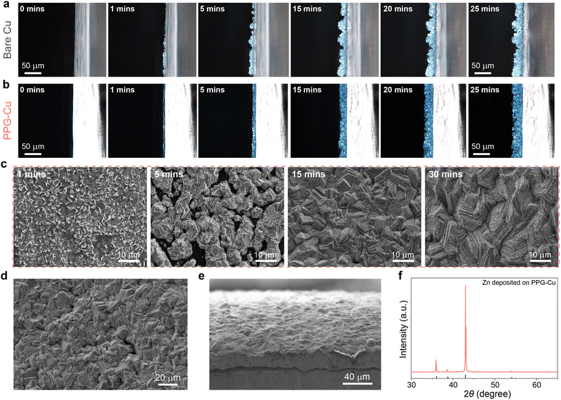
Zn plating/stripping pattern was monitored under an in situ optical microscope and the results are shown in Fig. 3a and b. As expected, uneven Zn deposition could be observed for the bare Cu at the initial stage (Fig. 3a). Consequently, such an inhomogeneous nucleation process caused the accumulation of charges at the pointed tip of the surface, and this led greater extent of Zn deposition at the tips, which ultimately resulted in more dendrites formed during the deposition process.23 As such, several visible protuberances appeared after 25 minutes of deposition and these protuberances continued to grow into Zn dendrites. This phenomenon was further confirmed by the cross-sectional SEM images in Fig. S6.† In contrast, a smooth surface morphology was observed for the entire plating process for PPG-Cu electrode, without any visible dendrites detected (Fig. 3b). This is because Zn2+ tends to gather around the protruding Zn to achieve uniform and horizonal deposition, as guided by the positively polarized P(VDF-TrFE). The growth process is further investigated by depositing Zn on PPG-Cu at different time intervals, and the SEM images are shown in Fig. 3c. Due to the lattice matching between graphene and zinc, Zn could nucleate and grow in the shape of hexagonal nanosheets (1 min). Then, these hexagonal nanosheets grow around the larger hexagonal nucleation sites to form closely packed and uniformly stacked hexagonal nanosheets as guided by the electric field due to the positively polarized P(VDF-TrFE) (5 min). Subsequently, these nanosheets converge to form interdigitated stacked nanosheet morphology (15 min), and finally grow into tightly interlocked large nanosheets (30 min). This can be further confirmed by the results shown in Fig. 3d and e. Also, after 30 min of continuous deposition, the surface of PPG-Cu was fully covered by Zn, since only XRD peaks belonging to Zn were detected (Fig. 3f), which indicates homogenous deposition.
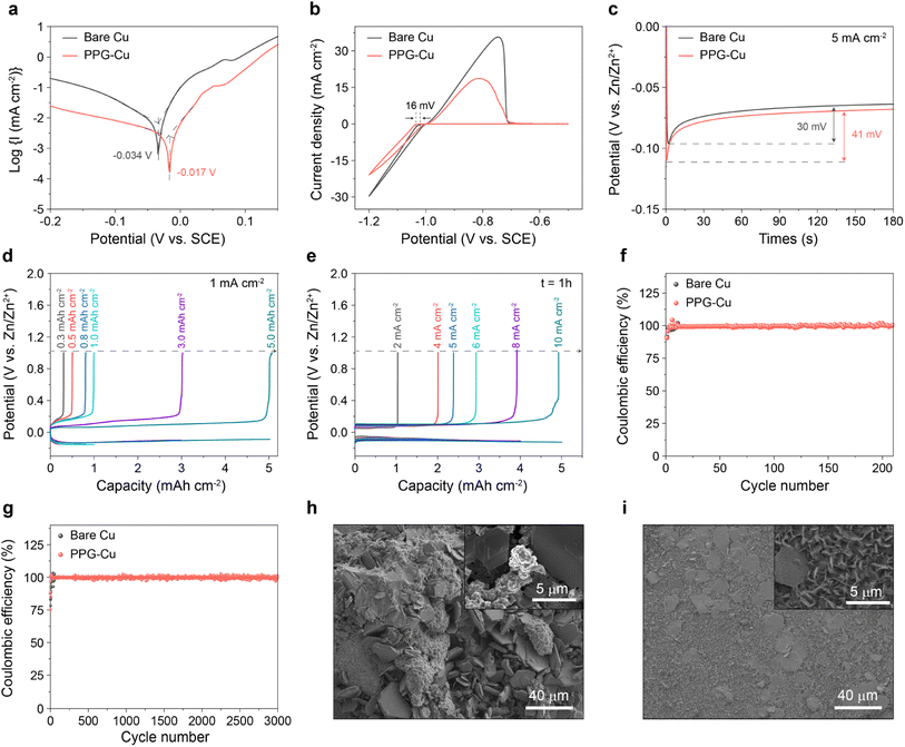
The effects of corrosion on the bare Cu and PPG-Cu were analysed by performing linear polarization experiments in 2 M ZnSO4 (Fig. 4a). When compared to the bare Cu, the corrosion potential of PPG-Cu increased from −0.034 V to −0.017 V. Most notably, a reduced corrosion current of 441 µA cm−2 was obtained for PPG-Cu as compared to that of bare Cu. It is generally accepted that a more positive corrosion potential indicates a lower tendency for corrosion, and a lower corrosion current will then indicate a lower corrosion rate.24 The nucleation stage is a pivotal step to understand the transformation process of Zn dendrites. As such, we proceeded to compare the nucleation overpotentials of bare Cu and PPG-Cu electrodes to clarify the role of PPG-Cu in modulating the Zn nucleation behavior. Cyclic voltammetry (CV) tests were conducted in a three-electrode configuration, in which Cu or PPG-Cu was used as the working electrode, Zn foil as the counter electrode, and saturated calomel electrode (SCE) as the reference electrode. As shown in Fig. 4b, PPG-Cu could increase the nucleation overpotential by 16 mV when compared to the bare Cu. Moreover, as depicted in Fig. 4c, both electrodes experienced a rapid voltage drop at the beginning of the Zn plating process, which corresponds to the nucleation process of metallic Zn on the surface of the heterogeneous electrode. When compared to the bare Cu, PPG-Cu electrode exhibited an increase in nucleation overpotential by 11 mV, which is consistent with the results shown in Fig. 4b. The increased overpotential is primarily attributed to the non-conductive nature of the P(VDF-TrFE) polymer. This polymer layer acts as a solid-state diffusion barrier, harmonizing the interfacial Zn2+ flux and facilitating the migration of Zn2+ species to the Cu surface. This, in turn, stabilizes the subsequent stage of Zn growth. Consequently, the increased overpotential provides a driving force for the nucleation and growth processes with a regular nucleus.25
Next, the electrochemical Zn plating/stripping behaviors on the bare Cu and PPG-Cu electrode were assessed at higher capacities. Prior to the test, the cell was pre-treated at 10 mA cm−2 with 10 mA h cm−2 for 5 cycles. As shown in Fig. S7 and S8,† plating–stripping efficiency of 99% was attained after 5 cycles, and the resistance grew much smaller as indicated by the electrochemical impedance spectroscopy. Also, the pre-treated samples were investigated by SEM, and some residual zinc could still be observed, which serves as the starting point for subsequent Zn2+ deposition and growth (Fig. S9†). Obviously, the PPG-Cu electrode revealed stable performance for 0.3 h plating and up to 5 h plating at 1 mA cm−2 (Fig. 4d). The electrochemical Zn plating/stripping behaviors on the bare Cu and PPG-Cu electrodes were also investigated at different current densities with a fix deposition duration of 1 h. As shown in Fig. 4e, the PPG-Cu electrode exhibited high coulombic efficiency approaching 99% at 2 mA cm−2 and up to 10 mA cm−2. Similarly, the bare Cu showed good Zn plating/stripping behavior at different current densities during initial cycles (Fig. S10†). The Zn plating–stripping efficiencies on bare Cu and PPG-Cu were evaluated by conducting galvanostatic discharge–charge cycles under 5 mA h cm−2 at 5 mA cm−2. As shown in Fig. 4f, the bare Cu electrode was only able to cycle for less than 50 cycles with such parameters. The reduced coulombic efficiency and unstable plating–stripping of Zn ions after prolonged cycling for bare Cu electrode could be due to the presence of Zn dendrites with large surface area that promotes the surface-originated and detrimental side reactions. In contrast, the stripping/plating of Zn on PPG-Cu electrode was highly stable throughout 200 cycles under identical electrochemical conditions. Moreover, even at high current density of 10 mA cm−2, the stripping/plating of Zn on PPG-Cu electrode remained stable for more than 3000 cycles (Fig. 4g), which is considered to be one of the longest lifespans ever reported for copper used for Zn ion battery (Table S1†). To further elucidate the mechanism behind the extended cyclic life, the morphologies of the cycled electrodes were analysed. As shown in Fig. 4h, random plates and dendrites were detected for the bare Cu, while uniform Zn deposition was observed for PPG-Cu (Fig. 4i). This result further proved the benefit of PPG-Cu in controlling the Zn dendrite formation during pro-longed cycling.
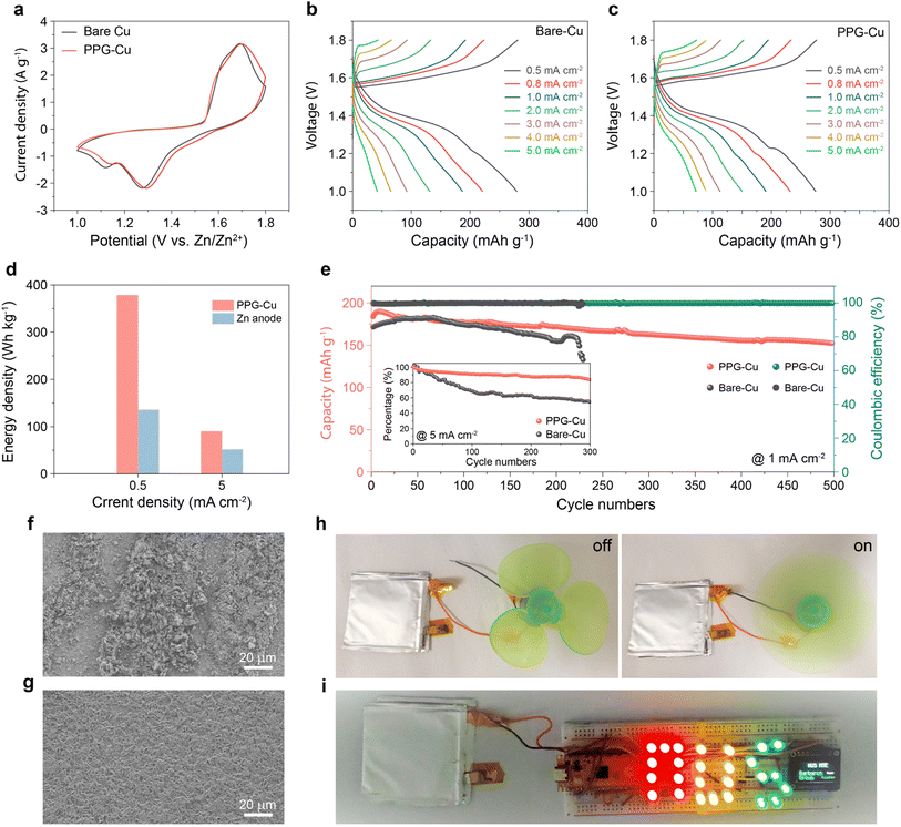
Inspired by the successful construction of dendrite-free PPG-Cu electrode, a PPG-Cu//MnO2 battery was assembled in 2 M ZnSO4 + 0.2 M MnSO4 to assess its effectiveness and practicability as full cell. Here, MnO2 was selected as cathode, and the XRD and SEM results indicated its layered nanosheet morphology (Fig. S11†).26 Prior to the battery assembly, MnO2 was electrochemically intercalated with Zn2+, as confirmed by Fig. S12.† Next, the electrochemical impedance spectroscopy (EIS) measurements were conducted to investigate the charge transfer resistance and Zn2+ ion diffusion resistance in the full cell. As shown in Fig. S13,† the smaller semicircles at the middle-frequency range of PPG-Cu//MnO2 cell indicated its lower charge transfer resistance (63.5 Ohm) as compared to that of Cu//MnO2 (100 Ohm). Also, the inclined line with larger slope at low frequencies observed for PPG-Cu//MnO2 cell indicated a faster Zn ion diffusion kinetics as compared to the Cu//MnO2 cell due to the electric field arising from the positively polarized ferroelectric polymer. As observed in Fig. 5a, both Cu//MnO2 and PPG-Cu//MnO2 batteries showed CV curves with similar shape profile, which indicates that the presence of coating did not affect the Zn ion intercalation/deintercalation behaviour.27
The galvanostatic charge/discharge curves of Cu//MnO2 and PPG-Cu//MnO2 are shown in Fig. 5b and c, respectively. Both batteries showed comparable performance of ca. 270 mA h g−1 at 0.5 mA cm−2. However, the bare Cu//MnO2 decayed faster with increasing current density. At 5 mA cm−2, the Cu//MnO2 battery delivered a low capacity of 46 mA h g−1, which is much lower than that of the PPG-Cu//MnO2 battery (75 mA h g−1). To verify the high energy density of our Zn metal-free battery, conventional Zn//MnO2 battery was assembled and tested (Fig. S14†). According to the result, Zn//MnO2 showed a slightly higher capacity of 310 mA h g−1 due to the high abundance of Zn2+ at the Zn anode. More importantly, PPG-Cu//MnO2 showed a higher energy density of 378 W h kg−1 at 0.5 mA cm−2 when compared to conventional Zn//MnO2 of 136 W h kg−1 (assuming the mass of Zn is twice the mass of MnO2 cathode). Even at 5 mA cm−2, PPG-Cu//MnO2 could deliver a high energy density of 90 W h kg−1 as compared to the conventional Zn ion battery (52 W h kg−1) (Fig. 5d). The long-term stability was also examined, and the results are shown in Fig. 5e. The PPG-Cu//MnO2 battery showed a capacity of 180 mA h g−1 in the first cycle, and it could retain a capacity of 153 mA h g−1 after cycling for 500 cycles at 1 mA cm−2 (corresponding to a capacity retention of 83%). This stability represents an improvement when compared to other reported zinc metal-free zinc-ion batteries, which exhibited 80% capacity retention at 0.5 mA cm−2 after 275 cycles14 and 68.2% capacity retention after 80 cycles.10 The cyclic stability can be further enhanced through future optimizations in electrolyte composition and cathode design. In contrast, Cu//MnO2 failed after 230 cycles under similar current density, which further highlights the attractiveness of PPG-Cu in enhancing the cyclic performance of the battery. For the cyclic test under high current density of 5 mA cm−2, the PPG-Cu//MnO2 battery managed a capacity retention of 83.4% after 300 cycles, while Cu//MnO2 showed significant decay of about 50% of its initial capacity after 300 cycles. Also, some dendrites and by-products were observed for the cycled Cu foil, while the surface of the cycled PPG-Cu remained smooth without visible dendrites (Fig. 5f and g). This result further confirmed that the coating of graphene and positive polarized polymer can aid in regulating the surface nucleation and growth dynamics in order to achieve a successful guided Zn growth during cycling. To demonstrate the usability of the cell, two pouch cells were constructed and were connected in series to successfully power the electric fan (Fig. 5h) and LED lights (Fig. 5i).
Conclusion
In summary, we reported a facile strategy to regulate the nucleation and growth of Zn by introducing graphene and positively polarized P(VDF-TrFE) on the surface of a Cu substrate. The as-assembled half-cell was able to operate stably for 3000 cycles at a high current density of 10 mA cm−2 with a capacity of 1 mA h cm−2. As a proof-of concept, we have demonstrated a Zn metal-free battery prototype with decent stability (83% after 500 cycles at 1 mA cm−2) and high energy density (378 W h kg−1 at 0.5 mA cm−2). It is noted that even after extended cycling, the surface morphology of the modified Cu substrate remained smooth without any visible dendrites, while a significant amount of Zn dendrites could be observed for the unmodified counterpart. This demonstrated the effectiveness of the synergistic effects of graphene and positively polarized P(VDF-TrFE) in achieving a horizontal and in-plane deposition of Zn during the electrochemical process. As a demonstration, two pouch cells were connected in series to successfully power the electric fan and LED lights. The versatility of our concept depends on the low-cost technique, naturally abundant materials, and aqueous processing. The Zn metal-free batteries concept will play an essential ideation in constructing cost-effective, high-performance aqueous batteries for stationary grid storage.Data availability
Data will be made available on request.Author contributions
T. X. and D. Z. contributed equally to this work. T. X., D. Z. and B. Ö. conceived the idea. T. X. and D. Z. performed synthesis and electrochemical measurement and co-wrote the manuscript. J. Y. Y performed the atomic force microscopy and Kelvin probe force microscopy tests. Y. Z. performed the simulation and the figure drawing. Y. K. O., C. M. A. L., L. S., Y. R., Y. P., W. L. and J. L., were responsible for the analysis of electrochemical results. W. S. V. L. helped to polish the manuscript. B. Ö. is in charge of the overall project.Conflicts of interest
The authors declare that they have no known competing financial interests or personal relationships that could have appeared to influence the work reported in this paper.Acknowledgements
This research is supported by Competitive Research Programme (CRP award number NRF-CRP22-2019-008) by the National Research Foundation, Prime Minister's Office, Singapore (B. Ö.). Medium-Sized Centre Programme (CA2DM), by Ministry of Education of Singapore, under its Research Centre of Excellence award to the Institute for Functional Intelligent Materials (I-FIM, Project No. EDUNC-33-18-279-V12) (B. Ö.), Space Technology Development Programme (S22-19013-STDP) by EDB Singapore (B. Ö.).References
- I. Buchmann, Batteries in a Portable World: A Handbook on Rechargable Batteries for Non-engineers, Cadex Electronics Inc., British Columbia 2001 Search PubMed.
- Y. Liang, C. Z. Zhao, H. Yuan, Y. Chen, W. Zhang, J. Q. Huang, D. Yu, Y. Liu, M. M. Titirici, Y. L. Chueh, H. Yu and Q. Zhang, Infomat, 2019, 1, 6–32 CrossRef CAS.
- A. G. Olabi, Q. Abbas, P. A. Shinde and M. A. Abdelkareem, Energy, 2023, 266, 126408 CrossRef CAS.
- Y. Tian, Y. An, C. Wei, H. Jiang, S. Xiong, J. Feng and Y. Qian, Nano Energy, 2020, 78, 105344 CrossRef CAS.
- W. Yao, P. Zou, M. Wang, H. Zhan, F. Kang and C. Yang, Electrochem. Energy Rev., 2021, 4, 601–631 CrossRef CAS.
- S. Nanda, A. Gupta and A. Manthiram, Adv. Energy Mater., 2021, 11, 2000804 CrossRef CAS.
- K. Lee, Y. J. Lee, M. J. Lee, J. Han, J. Lim, K. Ryu, H. Yoon, B. H. Kim, B. J. Kim and S. W. Lee, Adv. Mater., 2022, 34, 2109767 CrossRef CAS PubMed.
- G. Wang, M. Zhu, G. Chen, Z. Qu, B. Kohn, U. Scheler, X. Chu, Y. Fu, O. G. Schmidt and X. Feng, Adv. Mater., 2022, 34, 2201957 CrossRef CAS PubMed.
- M. Song, H. Tan, D. Chao and H. J. Fan, Adv. Funct. Mater., 2018, 28, 1802564 CrossRef.
- Y. Zhu, Y. Cui and H. N. Alshareef, Nano Lett., 2021, 21, 1446–1453 CrossRef CAS PubMed.
- Z. Xie, Z. Wu, X. An, X. Yue, J. Wang, A. Abudula and G. Guan, Energy Storage Mater., 2020, 32, 386 CrossRef.
- T. Foroozan, V. Yurkiv, S. Sharifi-Asl, R. Rojaee, F. Mashayek and R. Shahbazian-Yassar, ACS Appl. Mater. Interfaces, 2019, 11, 44077–44089 CrossRef CAS PubMed.
- S. Xie, Y. Li and L. Dong, J. Energy Chem., 2023, 76, 32–40 CrossRef CAS.
- F. Ming, Y. Zhu, G. Huang, A. H. Emwas, H. Liang, Y. Cui and H. N. Alshareef, J. Am. Chem. Soc., 2022, 144, 7160–7170 CrossRef CAS PubMed.
- Y. An, Y. Tian, K. Zhang, Y. Liu, C. Liu, S. Xiong, J. Feng and Y. Qian, Adv. Funct. Mater., 2021, 3, 2101886 CrossRef.
- X. Zheng, Z. Liu, J. Sun, R. Luo, K. Xu, M. Si, J. Kang, Y. Yuan, S. Liu, T. Ahmad, T. Jiang, N. Chen, M. Wang, Y. Xu, M. Chuai, Z. Zhu, Q. Peng, Y. Meng, K. Zhang, W. Wang and W. Chen, Nat. Commun., 2023, 14, 76 CrossRef CAS PubMed.
- J. Zheng, Q. Zhao, T. Tang, J. Yin, C. D. Quilty, G. D. Renderos, X. Liu, Y. Deng, L. Wang, D. C. Bock, C. Jaye, D. Zhang, E. S. Takeuchi, K. J. Takeuchi, A. C. Marschilok and L. A. Archer, Science, 2019, 366, 645–648 CrossRef CAS PubMed.
- Y. Wang, T. Guo, J. Yin, Z. Tian, Y. Ma, Z. Liu, Y. Zhu and H. N. Alshareef, Adv. Mater., 2022, 34, 2106937 CrossRef CAS PubMed.
- Z. Ni, Y. Wang, T. Yu and Z. Shen, Nano Res., 2008, 1, 273–291 CrossRef CAS.
- L. M. Malard, M. A. Pimenta, G. Dresselhaus and M. S. Dresselhaus, Phys. Rep., 2009, 473, 51–87 CrossRef CAS.
- A. Arrigoni, L. Brambilla, C. Bertarelli, G. Serra, M. Tommasini and C. Castiglioni, RSC Adv., 2020, 10, 37779–37796 RSC.
- G. Min, A. Pullanchiyodan, A. S. Dahiya, E. S. Hosseini, Y. Xu, D. M. Mulvihill and R. Dahiya, Nano Energy, 2021, 90, 106600 CrossRef CAS.
- Q. Zhang, J. Luan, X. Huang, L. Zhu, Y. Tang, X. Ji and H. Wang, Small, 2020, 16, 2000929 CrossRef CAS PubMed.
- M. Abdallah, Corros. Sci., 2003, 45, 2705–2716 CrossRef CAS.
- Z. Zhao, J. Zhao, Z. Hu, J. Li, J. Li, Y. Zhang, C. Wang and G. Cui, Energy Environ. Sci., 2019, 12, 1938–1949 RSC.
- T. Xiong, Z. G. Yu, H. Wu, Y. Du, Q. Xie, J. Chen, Y. ‐W. Zhang, S. J. Pennycook, W. S. V. Lee and J. Xue, Adv. Energy Mater., 2019, 9, 1803815 CrossRef.
- H. Pan, Y. Shao, P. Yan, Y. Cheng, K. S. Han, Z. Nie, C. Wang, J. Yang, X. Li, P. Bhattacharya, K. T. Mueller and J. Liu, Nat. Energy, 2016, 1, 16039 CrossRef CAS.
Footnotes |
| † Electronic supplementary information (ESI) available. See DOI: https://doi.org/10.1039/d3ta07674a |
| ‡ These authors contributed equally to this work. |
| This journal is © The Royal Society of Chemistry 2024 |

