
 Open Access Article
 This Open Access Article is licensed under a Creative Commons Attribution-Non Commercial 3.0 Unported Licence
Tin–lead halide perovskite solar cells with a robust hole transport layer†
Chunyan
Li‡
a,
Yao
Zhang‡
 a,
Haiyan
Zhao
a,
Zhongxun
Yu
a,
Jixiang
Zhang
a,
Peng
Zhang
ab and
Han
Chen
*abc
a,
Haiyan
Zhao
a,
Zhongxun
Yu
a,
Jixiang
Zhang
a,
Peng
Zhang
ab and
Han
Chen
*abc
aState Key Laboratory of Metal Matrix Composites, Shanghai Jiao Tong University, Shanghai 200240, China. E-mail: chen.han@sjtu.edu.cn
bJoint Research Center for Clean Energy Materials, Shanghai Jiao Tong University, Shanghai 200240, China
cInnovation Center for Future Materials, Zhangjiang Institute for Advanced Study, Shanghai Jiao Tong University, Shanghai 201203, China
First published on 13th March 2024
Abstract
The photovoltaic performance and stability of tin–lead perovskite solar cells (PSCs) are undermined by the reaction between the perovskite layer and the commonly used hole contact, poly(3,4-ethylenedioxythiophene)![[thin space (1/6-em)]](https://www.rsc.org/images/entities/char_2009.gif) :polystyrene sulfonate (PEDOT:PSS). In addition to its acidity issue, the PSS polyelectrolyte can be etched by polar solvents within the perovskite precursor, exposing the highly doped PEDOT chains and resulting in carrier quenching at the buried interface. Here, an inorganic salt, cesium carbonate (CC), is incorporated to convert the labile PEDOT:PSS mixture into a robust polymer substrate. The salt induces substantial morphological transformation in the polymer matrix with enhanced interchain coupling, rendering the PEDOT:PSS resistant to polar solvents. The modified hole contact suppresses redox reactions, chemical degradation, and recombination losses at the buried interface. Single-junction methylammonium-free tin–lead PSCs achieved an efficiency of 23.18% (certified 22.30%). The encapsulated device retained 91% of its initial efficiency after 500 hours of maximum power point operation under AM1.5G one-sun illumination.
:polystyrene sulfonate (PEDOT:PSS). In addition to its acidity issue, the PSS polyelectrolyte can be etched by polar solvents within the perovskite precursor, exposing the highly doped PEDOT chains and resulting in carrier quenching at the buried interface. Here, an inorganic salt, cesium carbonate (CC), is incorporated to convert the labile PEDOT:PSS mixture into a robust polymer substrate. The salt induces substantial morphological transformation in the polymer matrix with enhanced interchain coupling, rendering the PEDOT:PSS resistant to polar solvents. The modified hole contact suppresses redox reactions, chemical degradation, and recombination losses at the buried interface. Single-junction methylammonium-free tin–lead PSCs achieved an efficiency of 23.18% (certified 22.30%). The encapsulated device retained 91% of its initial efficiency after 500 hours of maximum power point operation under AM1.5G one-sun illumination.
Introduction
Tin–lead halide perovskites hold great promise as light-harvesting semiconductors in both single-junction solar cells and all-perovskite tandems.1–8 Extending light absorption to a near-infrared region (∼1050 nm), the incorporation of tin also introduces several challenging issues compared to pure-lead perovskites, including the susceptibility of Sn(II) to oxidation into Sn(IV),9–11 rapid crystallization,12,13 and inferior operational stability.14,15 In recent years, extensive research efforts have been devoted to addressing these concerns and significant improvements have been achieved. However, the stability of tin–lead perovskites is still constraining their application, with a crucial factor being the threat from PEDOT:PSS which commonly serves as the deposition substrate and hole transport layer (HTL).
A solution-processed PEDOT:PSS thin film is a polymer mixture composed of two distinct phases: the hole-conductive hydrophobic PEDOT-rich cores and the surrounding insulating hydrophilic PSS-rich shells.16,17 To synthesize PEDOT:PSS HTL, the polystyrene sulfonate acid (PSSH) is introduced in a predominant amount to stabilize the oxidized PEDOT oligomer and achieve a high work function.18 In the case of the Clevious P VP AI 4083, the PSS/PEDOT weight ratio stands at 6:1. The strong acidity and hygroscopic nature of the PSS shell can trigger decomposition of the tin–lead perovskite lattice, particularly under photo or heat stress.19,20 Various strategies have been reported to address this issue, such as replacing PEDOT:PSS with non-acidic HTL,8,21–24 surface modification,25–27 PH neutralization,28,29 and HTL-free devices.30,31 However, to date, most of the high-performing tin–lead single-junction PSCs and all-perovskite tandems are still employing prototype PEDOT:PSS, impeding further development.
In addition to the notorious acidity, the polyelectrolyte nature of the PSSH shell renders it susceptible to polar solvent etching,32 such as dimethylformamide (DMF) and dimethyl sulfoxide (DMSO). This vulnerability poses a challenge for using PEDOT:PSS as a substrate for the solution-processed halide perovskite. The PSSH chains dissolving into perovskite precursor could remain in the polycrystalline perovskite film and trigger decomposition from the inside. Furthermore, the PSSH macromolecules surrounding the highly doped PEDOT-rich cores can effectively prevent direct contact between the perovskite absorber and the conducting PEDOT chains. It has been reported that removal of the PSSH shell can lead to carrier quenching at the perovskite/HTL interface, decreasing device performance.33–35
In this work, we concurrently alleviate the acidity of PEDOT:PSS and construct a robust polymeric HTL substrate by incorporating an inorganic salt, cesium carbonate (CC). The introduction of CC into PEDOT:PSS induces a screening effect that reduces the electrostatic interactions between the charges on PEDOT and its PSS counter-anion, leading to a conformational change of the polymer chains and enhanced interchain interactions. The modified PEDOT:PSS film shows negligible solubility in polar organic solvent and slightly increased conductivity. As a result, tin–lead perovskite layers deposited on the modified PEDOT:PSS exhibit enhanced crystallization and suppressed degradation. Moreover, by combining the CC doping with a solvent treatment, methylammonium (MA)-free tin–lead PSCs achieved an efficiency of 23.18%, along with significantly enhanced stabilities under thermal and operational stress.
Results and discussion
Effect of CC incorporation on PEDOT![[thin space (1/6-em)]](https://www.rsc.org/images/entities/h3_char_2009.gif) :PSS properties
:PSS properties
The incorporation of CC was proceeded by mixing PEDOT:PSS dispersion and the aqueous solution of CC (50 mg mL−1) in the volume ratio of 10:1. Atomic force microscopy (AFM, Fig. 1a) and tunneling AFM (TUNA, Fig. 1b) measurements were conducted to study the effects of CC on the morphology and conductivity of the PEDOT:PSS thin films. The pristine PEDOT:PSS presents a smooth and amorphous surface, while the CC-doped sample is relatively rough and packed with granules. A higher concentration of the Cs2CO3 additive results in slightly enlarged granules (Fig. S1†), assumably owing to a more intensified reconfiguration of the polymer chains. This distinct morphologic change suggests a conformational transformation of the polymer chains owing to the salt-induced screening effect.36
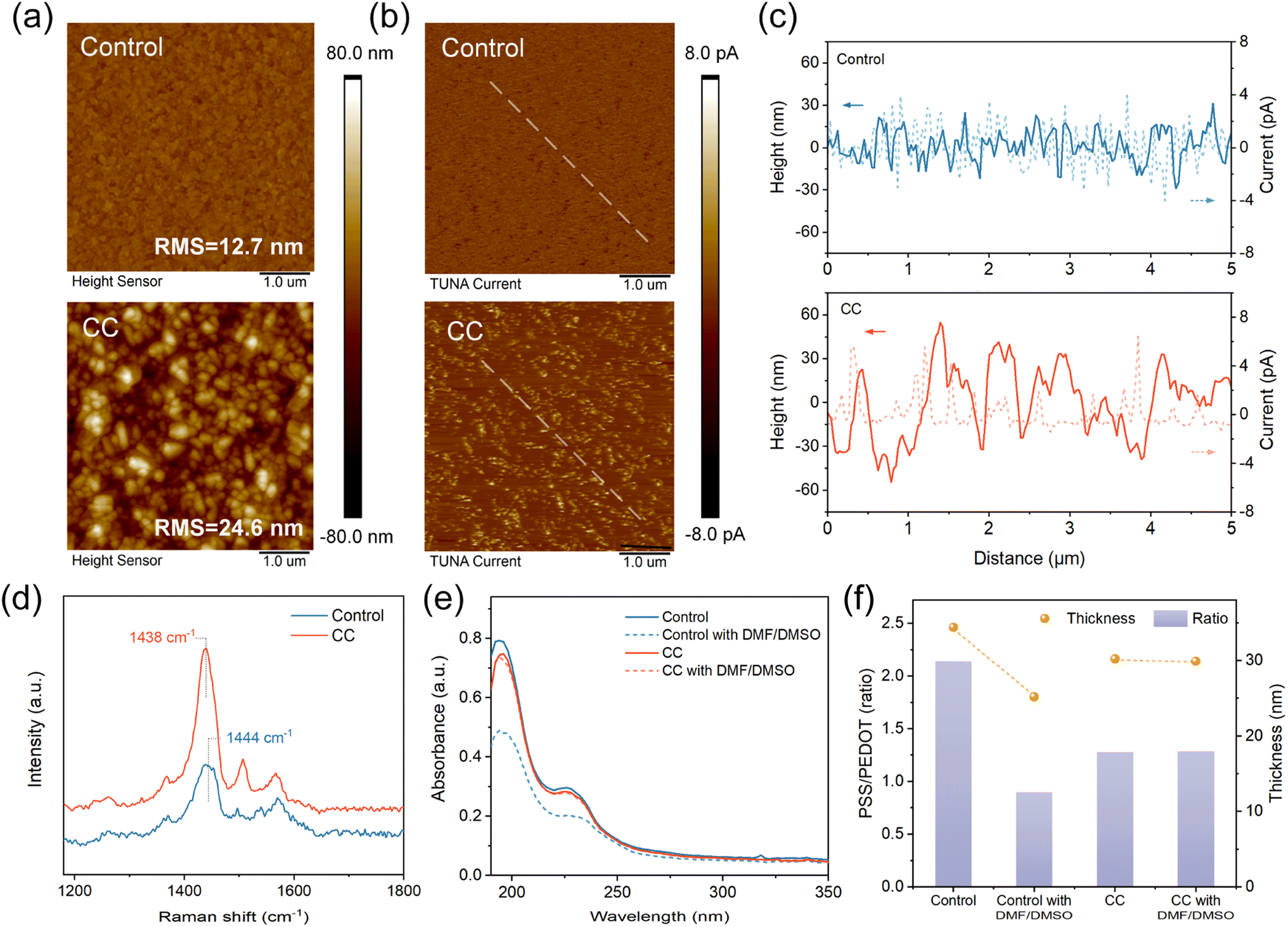 | ||
| Fig. 1 (a) AFM morphology, (b) tunneling AFM current mapping, and (c) height/current along scan distance of the PEDOT:PSS films without (control) and with CC; the scan is along a line shown in the picture of (b). (d) Raman spectra of the PEDOT:PSS films without (control) and with CC. (e) UV absorption spectra of the PEDOT:PSS films without and with DMF/DMSO treatment. (f) Layer thickness and PSS/PEDOT molar ratio of the PEDOT:PSS films without and with DMF/DMSO treatment. | ||
The conformation of PEDOT oligomers was studied by Raman spectroscopy (Fig. 1d). The stretching vibration of Cα = Cβ on the thiophene ring induces a characteristic band between 1400 and 1500 cm−1, which shifts to red and becomes narrower with CC incorporated. The result reveals a transition from an aromatic structure to a quinoid structure.37 The quinoid resonant structure favors linear or extended configurations of the conjugated chains, promoting interchain interactions within the thin film.38,39 In the TUNA images (Fig. 1b), the control PEDOT:PSS shows a low average tunneling current owing to the insulting PSSH covering. In contrast, spots of higher conductivity appear in the CC sample, indicating that the granule conformation can facilitate interchain charge transfer. In addition, the line profiles derived from height and current mapping were presented in Fig. 1c. The height and current distribution of the control film was homogenous but there were obvious height fluctuations and enlarged current in CC films, consistent with the previous analysis.
A solvent etching treatment using a DMF/DMSO (v/v 3:1) mixed solvent was applied to the PEDOT:PSS films, and UV-Vis-NIR absorption spectra (Fig. 1e) were collected to monitor the changes in PSS content within the films, as the short wavelength (190–250 nm) absorption corresponds to the π–π* transition of the benzene rings on the PSS chain. After the solvent washing, the control PEDOT:PSS film exhibited a significant decrease in PSS content, whereas the PSS content in the CC-doped sample barely decreased. AFM morphology of the washed CC-HTL demonstrates no conspicuous change (Fig. S2†), revealing its tolerance to the solvents. In contrast, the control sample exhibits a substantial transformation to large domains, owing to the etching and strong polarity of DMF/DMSO.37
The compositional changes in the PEDOT:PSS films are confirmed by X-ray photoelectron spectroscopy (XPS) measurements. Based on the S 2p core level signals (Fig. S3†), the derived PSS/PEDOT molar ratios are 2.14, 0.90, 1.28, and 1.27 for the control, treated control, CC, and treated CC samples, respectively (Fig. 1h). Spectroscopic ellipsometry (Fig. S4†) was also conducted to determine the thickness variation of the PEDOT:PSS films. The CC film (30.2 nm) is slightly thinner than the control PEDOT:PSS (34.4 nm), in consistent with the absorption spectra (Fig. 1d). Notably, the DMF/DMSO washing causes an obvious thickness reduction of the control sample from 34.4 nm to 25.2 nm, while the thickness of the CC sample decreases by 0.3 nm only (Fig. 1e). The photovoltaic performance data of the perovskite solar cells based on different PEDOT:PSS films were presented in Fig. S5.† Devices based on PEDOT:PSS etched with DMF/DMSO showed worse device performances and reproducibility due to the low Voc and FF. These results confirm the inertness of CC-doped PEDOT:PSS against the polar DMF/DMSO solvent.
The inertness of the CC-HTL is primarily attributed to the granular configuration induced by CC, which results in extended interchain interactions among the PEDOT backbones.37 The pH value of the PEDOT:PSS ink increased from 1.38 to 2.34 after CC addition (Fig. S6†). The CC, as a moderately strong base, readily undergoes an acid–base reaction with the acidic PSSH (pKa ∼ −7) in the aqueous dispersion, producing the carbonic acid (pKa ∼ 3.6) and the Cs:PSS polyelectrolyte. The reaction enthalpy obtained through density functional theory (DFT) calculations is −91.6 kJ mol−1 (Fig. S7†). The carbonic acid could further be removed from the HTL during annealing (160 °C). XPS results demonstrate the presence of Cs but no signal of the carbonate (Fig. S8†), confirming the occurrence of the reaction. Time-of-flight secondary-ion mass spectrometry (ToF-SIMS) measurement was performed to obtain the compositional depth profile throughout the HTL (Fig. S9†). The Cs ion is uniform for the most part of the layer with a slight enrichment at the surface, and no signal of carbonate is detected. In addition, as the solubility of PSS chains relies on intermolecular hydrogen bonding interactions to some degree, the deprotonation of PSS also renders it somewhat less soluble in DMF/DMSO.
The influences of CC on the electrical and optical properties of PEDOT:PSS are also studied. The transmittance spectra (Fig. S10†) demonstrate that the inclusion of CC results in a slightly increased transmittance, particularly around a wavelength of approximately 300 nm, owing to the partial loss of the PSS content. The electrical conductivity (Fig. S11†) slightly increases from 0.0727 S cm−1 of the control PEDOT:PSS to 0.0751 S cm−1 of the CC sample, in consistent with the TUNA result.
Characterization of perovskite films
To investigate the effect of CC on the buried PEDOT:PSS/perovskite interface, we peeled off the perovskite layer following a reported technique.40,41 The scanning electron microscope (SEM, Fig. 2a and b) results demonstrate the erosion occurs obviously at grain boundaries of the control perovskite owing to the acid control HTL, whereas the target film presents a flat and dense morphology. Deterioration of the buried interface would cause poor interface contact and formation of electronic trap states. Moreover, the target perovskite film on CC-HTL also displays larger crystal grains, which are also evident in the SEM images of the top surface (Fig. S12†). The increased grain size is attributed to the slightly decreased wettability of the CC-HTL substrate (Fig. S13†).
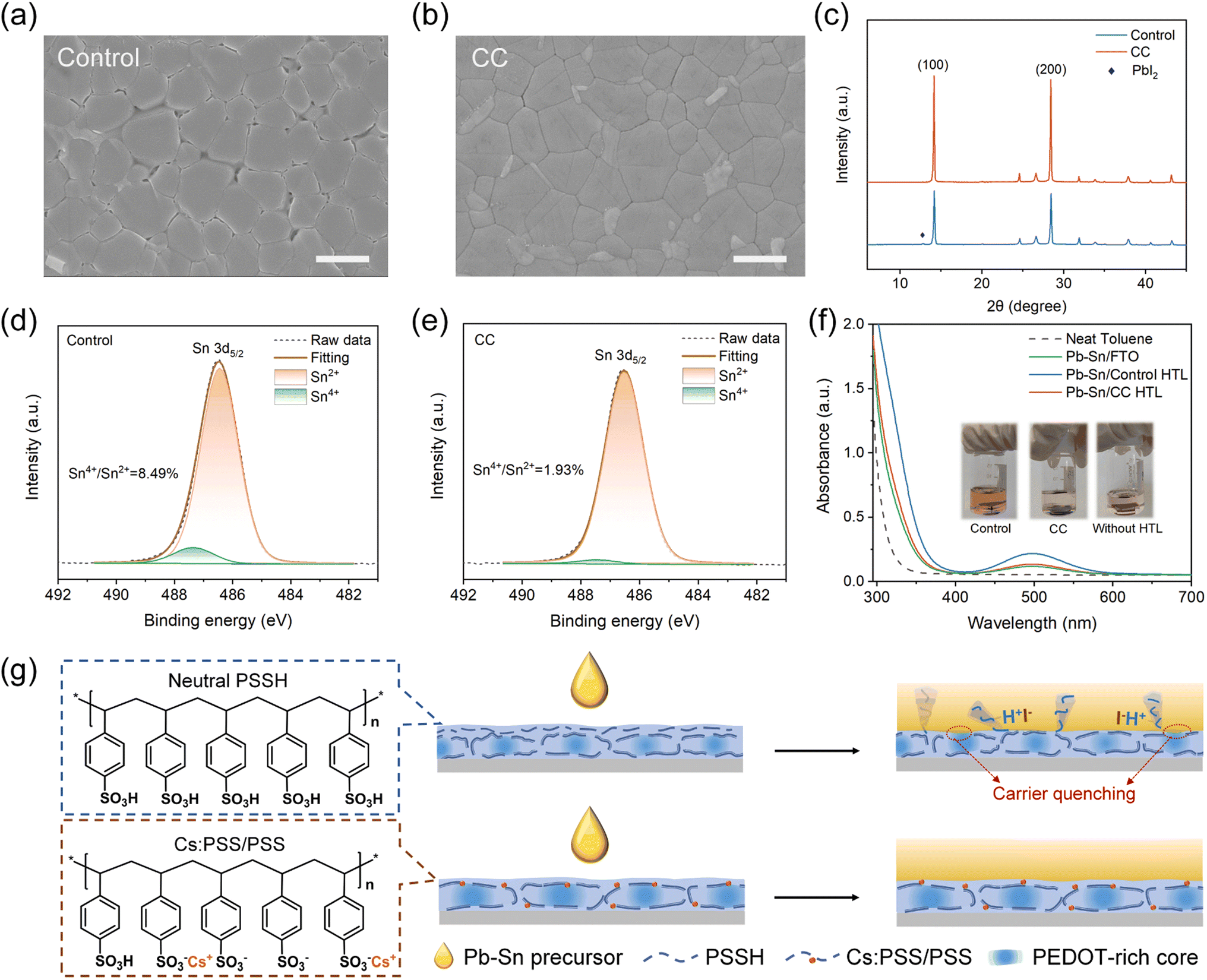 | ||
| Fig. 2 SEM images of the buried interface of the perovskite films fabricated on (a) control PEDOT:PSS and (b) CC-doped PEDOT:PSS. Scale bar, 500 nm. (c) XRD patterns of perovskite films grown on the control and CC-HTL layers. The XPS Sn 3d5/2 spectra of the perovskite layers deposited on (d) control PEDOT:PSS and (e) CC-doped PEDOT:PSS, measured at the bottom surface. (f) Absorbance spectra of toluene solutions in which perovskite films were immersed under 1-sun illumination for 48 hours. (g) Schematic illustration of the mechanisms of CC doping in PEDOT:PSS. | ||
The X-ray diffraction (XRD, Fig. 2c) patterns demonstrate enhanced crystallinity of the target perovskite. A diffraction signal of PbI2 is observed in the control perovskite while the target sample shows no trace of PbI2, suggesting that CC-HTL prevents decomposition of tin–lead perovskite at the buried interface. Furthermore, derived from the UV-Vis-NIR absorption spectra (Fig. S14†), the Urbach energies of the perovskite films deposited on the control and CC-HTL are 67.5 meV and 58.6 meV, respectively, suggesting enhanced crystallinity and reduced in-gap states of the CC sample.
XPS measurements (Fig. 2d and e) were performed to determine the presence of tetravalent tin (Sn4+) at the buried interface. The Sn 3d5/2 core level spectra are divided into two distinct signals, peaking at 486.4 and 487.5 eV, corresponding to the Sn2+ and Sn4+, respectively. The estimated proportions of Sn4+ in the buried interface for the control and CC-doped samples are 8.49% and 1.93%, indicating suppressed oxidation degradation in the target sample. Additionally, a sulfur signal is detected at the buried surface of the control perovskite (Fig. S15†), which is absent in the target. The presence of sulfur is attributed to the PSS chains residing within the perovskite grain boundaries. This observation suggests that the incorporation of CC can prevent PSS macromolecules from infiltrating the perovskite film.
Acceleration of tin oxidation by acidic PEDOT:PSS has been reported in the literature.25,42 A potential oxidation route without the participation of oxygen is:
| PSSH + I− → PSS− + HI | (1) |
 | (2) |
| Sn2+ + I2 → Sn4+ +2I− | (3) |
:PSS films were immersed in toluene and subjected to AM1.5G one-sun illumination for 48 h. As indicated in the absorption spectra of the toluene solutions (Fig. 2f), the perovskite on control HTL exhibits a significantly higher production of I2, whereas the I2 generated in the CC-HTL is significantly lower, nearly as same as that of the sample without an HTL. The mechanisms behind CC inhibiting tin oxidation are illustrated in Fig. 2g. In addition to the neutralization effect, the removal of the dissolvable amorphous PSS shell and conformational change make the CC-HTL a robust polymer substrate, preventing the infiltration of PSSH chains into the perovskite layer to erode the soft perovskite lattice.
The influence of CC on the surface electronic properties of PEDOT:PSS was explored through ultraviolet photoelectron spectroscopy (UPS, Fig. 3a and b) and Kelvin probe force microscopy (KPFM). The CC-PEDOT:PSS exhibits a higher work function value than that of the control. KPFM measurements (Fig. S16†) show consistent results that the CC-PEDOT:PSS exhibits a slightly deeper surface potential, which is attributed to the conformational change of the polymer chains.38 In addition, the UPS results of the bottom surface of perovskite film deposited on different HTLs are shown in Fig. S17.† Compared with the control, perovskite film deposited on the CC-HTL exhibits a shallower work function. This is indicative of reduced p-type doping of the target perovskite, which is ascribed to suppressed oxidation degradation at the buried interface.
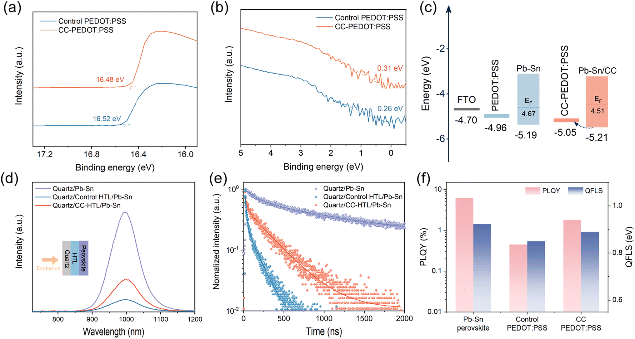 | ||
| Fig. 3 UPS spectra of the control and CC-PEDOT:PSS films, (a) cut-off region and (b) valence band edge region. (c) Energy level diagram of the FTO/HTL/perovskite half stack. (d) PL spectra, (e) time-resolved PL spectra, and (f) PLQY and QFLS values for neat perovskite film, perovskite/control HTL, and perovskite/CC-HTL. | ||
Based on the UPS data, the energy level diagram concerning hole extraction is constructed (Fig. 3c). The CC-PEDOT:PSS demonstrates a more favorable energy level alignment with the Pb–Sn perovskite, which can reduce charge carrier thermalization loss and contribute to a higher open-circuit voltage (VOC) of the solar cells.
Photoluminescence (PL, Fig. 3d) and time-resolved PL (TRPL, Fig. 3e) spectra were collected to assess non-radiative recombination at the buried interface. Tin–lead perovskite deposited on the CC-HTL exhibits a higher quench-limited emission intensity compared to the control sample. The PL spectra with excitation coming from the perovskite side (Fig. S18†) were also collected, the intensity enhancement induced by CC is somewhat less pronounced, as compared with the PL spectra excited from the glass side. This suggests that CC-HTL mainly suppresses the non-radiative recombination occurring at the buried interface. The diffusion-limited carrier lifetimes derived from the TRPL decay were shown in Table S2.† As the τ1 values of the control HTL/perovskite and CC-HTL/perovskite samples are significantly reduced than the quartz/perovskite sample, we relate τ1 to the hole extraction process at the buried contact. The τ2 is attributed to recombination that occurred in the perovskite layer. The higher τ2 of CC-HTL sample reveals a perovskite film of higher optoelectronic quality.
Furthermore, tin–lead perovskite layers deposited on the CC-HTL afford a higher PL quantum yield (PLQY) and a 40 meV larger quasi-Fermi-level splitting (QFLS) compared to their analogs on the control PEDOT:PSS substrate (Fig. 3f and Table S3†), indicating larger VOC values can be expected in devices incorporating CC. In addition to defects induced by bottom surface erosion, the high non-radiative recombination rate in the control sample is also attributed to potential contact between the perovskite and conducting PEDOT chains, with the PSS shell being etched by DMF and DMSO solvent. Insight into the interfacial charge transport occurring in the devices based on different HTLs is further gained by electrochemical impedance spectroscopy (EIS, Fig. S19†). The device with CC-PEDOT:PSS displayed a smaller Rct and a larger Rrec than the control device (Table S4†), revealing reduced defect-assisted traps and enhanced charge transfer.
Photovoltaic performances
We fabricated MA-free tin–lead PSCs with the architecture FTO/PEDOT:PSS/Rb0.03Cs0.2FA0.77Pb0.5Sn0.5I3/PCBM/C60/BCP/Cu (Fig. 4a), where PCBM is phenyl-C61-butyric-acid-methyl-ester and BCP is bathocuproine. In addition to incorporating CC, we introduced a solvent treatment (ST) technique to further modify the PEDOT:PSS substrate; devices combining CC and ST are denoted as CCST. The modification of the PEDOT:PSS HTL by polar solvent has been extensively researched. While high-boiling-point solvents, such as DMF and DMSO, would lead to decreased VOC,33,34 alcohols have demonstrated positive effects.43–45 Here, a co-solvent of methanol and ethylene glycol (volume ratio 30:1) was employed to treat the HTLs.
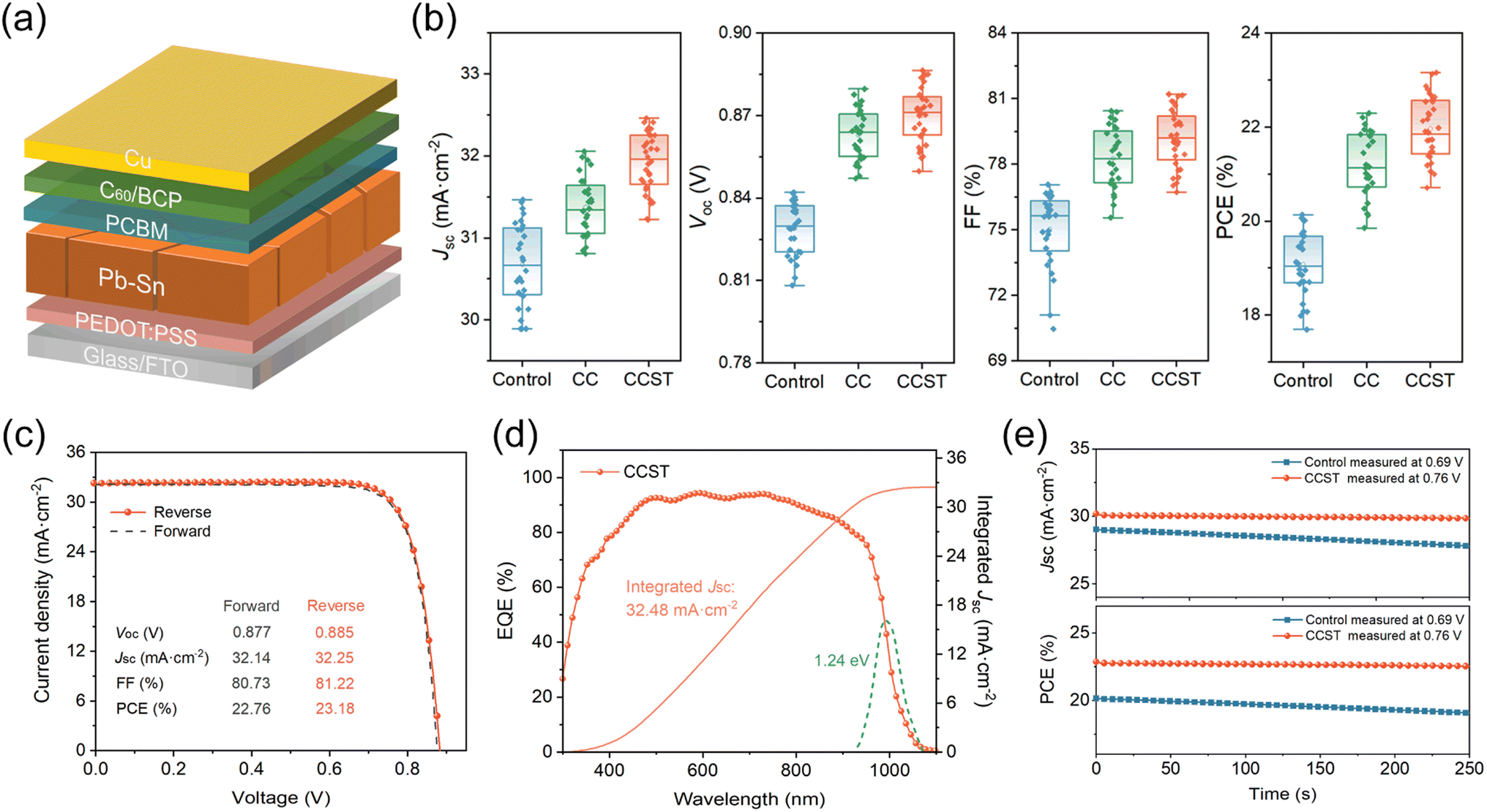 | ||
| Fig. 4 (a) Device architecture of Sn–Pb PSCs. (b) Statistics of the photovoltaics parameters of the control, CC, and CCST PSCs. (c) J–V curves of the champion CCST device. (d) EQE spectra and the integrated JSC of the CCST device; (e) steady-state photocurrent and PCE output at the maximum power point. | ||
The statistical distributions of photovoltaic parameters for control, CC, and CCST cells are presented in Fig. 4b. Compared to the control, the CC devices demonstrate enhancements in VOC, short circuit current density (JSC), and fill factor (FF), which is attributed to reduced recombination loss at the buried interface. However, over-doping of CC would decline the device performances (Fig. S20†), as a result of increased electrical resistance of the PEDOT:PSS layer due to the dedoping effect. The CCST cells present higher JSC than the CC cells, together with slightly enhanced VOC and FF, resulting from the improved hole conductivity of the PEDOT:PSS layers, as explored in the literature.37
The photovoltaic parameters of the champion devices were displayed in Table 1. A PCE of 23.18% under reverse scan is achieved by the CCST cells, with a JSC of 32.25 mA cm−2, VOC of 0.885 V, and FF of 81.22%, representing one of the highest PCEs for MA-free tin–lead PSCs to date (Table S5†). As observed in the J–V curves (Fig. 4c), the CCST cells also feature negligible hysteresis, suggesting reduced charge carrier accumulation at the buried interface.46 The cell was also measured in an accredited laboratory (Test and Calibration Centre of the New Energy Device and Module, SIMIT, Chinese Academy of Sciences). The certified PCE under reverse scan is 22.30% with a JSC of 31.79 mA cm−2, VOC of 0.870 V, and a FF of 80.60%, and the result also shows a small hysteresis (Fig. S21†). The external quantum efficiency (EQE) spectrum of the champion cell was presented in Fig. 4d, and the integrated JSC is 32.48 mA cm−2, consistent with the Jsc value obtained from the J–V curves. We recorded 250 seconds maximum power point (MPP) outputs for the control and CCST cells (Fig. 4e). In contrast to the prominent decay of the control cell, the CCST cell shows a steady efficiency of 22.6% during the operation.
| Devices | Scan | V oc (V) | J sc (mA cm−2) | FF (%) | PCE (%) |
|---|---|---|---|---|---|
| Control | Reverse | 0.834 | 31.45 | 77.12 | 20.23 |
| Forward | 0.816 | 31.12 | 75.91 | 19.28 | |
| CC | Reverse | 0.879 | 31.95 | 80.14 | 22.51 |
| Forward | 0.865 | 31.83 | 79.42 | 21.87 | |
| CCST | Reverse | 0.885 | 32.25 | 81.22 | 23.18 |
| Forward | 0.877 | 32.14 | 80.73 | 22.76 |
The dark J–V characteristics (Fig. S22†) reveal the CCST device exhibits a low saturation current density roughly one order of magnitude lower than that of the control device. The hole trap densities of the devices were estimated by space charge limited current (SCLC) measurements. As shown from the J–V characteristics of the hole-only devices (Fig. S23†), the trap-filled limit voltages of the control and CCST devices are 0.483 V and 0.440 V, corresponding to hole trap densities of 3.921 × 1015 cm−3 and 3.572 × 1015 cm−3, respectively. The results confirm the reduced nonradiative recombination at the buried perovskite/PEDOT:PSS interface.
To gain further insights, we conducted Mott–Schottky (M–S) analysis using capacitance–voltage measurements (Fig. S24†). The control device exhibited a built-in potential (Vbi) of 0.63 V, whereas the CCST device exhibited a notably higher Vbi of 0.68 V. This observed increase in Vbi aligns with the enhanced VOC of the target device, indicating the presence of a stronger electric field that facilitates better charge carrier separation and extraction at the interfaces. We also measured the light-intensity dependence of the VOC and derived the diode ideality factors (Fig. S25a†). The CCST cell exhibits a smaller ideality factor (1.29) than the control (1.62), indicating a decrease in trap-assisted non-radiative recombination. Similarly, Fig. S25b† shows the dependence of JSC on light intensity, expressed as Jsc ∝ Iα. The exponent α for the CCST device is closer to 1 than for the control device, suggesting that the bimolecular recombination has been suppressed.
Enhanced long-term stability
We first conducted storage stability tests following the ISOS-D-1I protocol,47 where unencapsulated devices were stored in an N2-filled glovebox in the dark under ambient temperature (20–25 °C). Both CC and CCST devices exhibited a ∼10% increase in PCE at the early stage (0–200 hours), which is assumably caused by the slow recovery of processing-induced defects in the bulk perovskite and interfaces in the devices. The CC and CCST devices retained 91% and 92% of the highest efficiency after 2000 hours, respectively (Fig. 5a). In contrast, the control devices experienced faster degradation during storage. This is probably caused by two factors, lower crystallinity of the perovskite film which may accelerate moisture intrusion and oxidation degradation,30 and the acidic PEDOT:PSS induced erosion reaction.28 We then raised the storage temperature to 85 °C to evaluate the thermal stability. Compared to the control, CC and CCST devices exhibited superior thermal stability, both retaining 88% of their initial PCE after 500 hours aging (Fig. 5b). XRD results demonstrate an increased PbI2 content in the control perovskite film after 500 hours of 85 °C thermal aging, while the CC film remains free of PbI2 (Fig. 5d). Moreover, cracks and voids appeared at the buried interface in the control device after thermal aging (Fig. 5e), which are absent in the CC device. These findings suggest that the rapid degradation of the control devices is rooted in the decomposition of tin–lead perovskite at the buried surface, which can be significantly mitigated by the incorporation of CC. To evaluate the operational stability, an encapsulated CCST cell was operated at maximum power point (MPP) condition under AM1.5G one-sun illumination in air (Fig. 5c), and the ambient temperature was maintained at 20–25 °C (ISOS-L-1I). The CCST device retained 91% of its initial PCE after 500 hours of MPP operation.
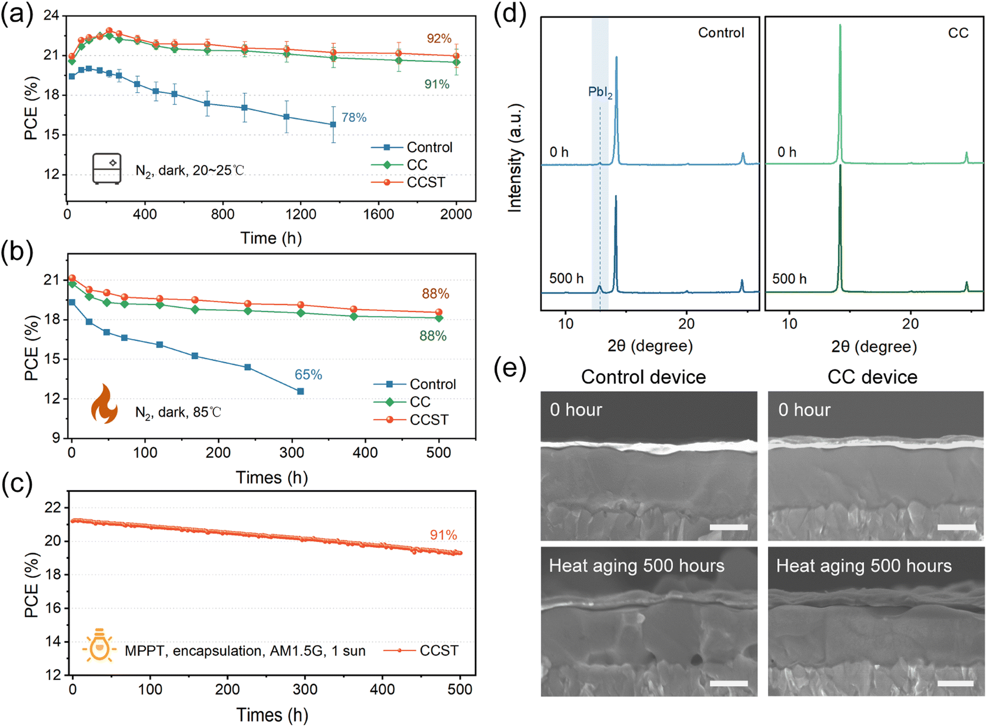 | ||
| Fig. 5 (a) Storage stability measurements, (b) thermal stability measurements of unencapsulated control, CC, and CCST devices. (c) MPP tracking measurement of an encapsulated CCST device. (d) The XRD of aged perovskite film on control and CC films at 85 °C for 500 hours. (e) Cross-SEM images of control and CC devices after heat aging for 500 hours. Scale bars, 500 nm. | ||
Conclusion
In summary, we doped the PEDOT:PSS by cesium carbonate to mitigate the acidity of the HTL and transform the polyelectrolyte substrate into a robust polymer matrix. The modified PEDOT:PSS is insoluble in polar organic solvent and the PSS chains are prevented from infiltrating the perovskite layer. The CC doping also contributes to a higher work function of the HTL and increased conductivity. Non-radiative recombination at the buried interface is suppressed, as well as the decomposition of the perovskite lattice. We achieved an efficiency of over 23% in MA-free tin–lead PSCs, with a degradation of less than 10% after 500 hours of MPP operation.
Author contributions
C. L. and Y. Z. contributed equally to this work. H. C. designed and directed the study. C. L. and Y. Z. fabricated the solar cell devices and carried out the main experimental work. C. L. and Y. Z. drafted the manuscript. C. L. performed the solar cell measurements and the stability test. H. Z., Z. Y. and J. Z. contributed to the characterizations. P. Z. and H. C. participated in the discussion. All authors revised the manuscript.Conflicts of interest
The authors declare no competing financial interest.Acknowledgements
This work was supported by the Top Young Talents of Ten Thousand Talents Plan, and the National Natural Science Foundation of China (grant no. 51902198). The authors acknowledge assistance in characterization from the staff of the Instrumental Analysis Center of Shanghai Jiao Tong University. Specifically, Qiyi Shan for assistance with C-AFM and KPFM measurements. Zhongqiu Bao for assistance with SEM measurements, Xue Ding for assistance with UPS and XPS measurements, Limin Sun for assistance with TOF-SIMS, and Ruibin Wang and Bangshang Zhu for assistance with PL, TRPL, and PLQY measurements. Minni Qu from the Center for Advanced Electronic Materials and Devices of SJTU for her help with spectroscopic ellipsometry.References
- F. Hao, C. C. Stoumpos, R. P. Chang and M. G. Kanatzidis, J. Am. Chem. Soc., 2014, 136, 8094–8099 CrossRef CAS PubMed.
- S. Hu, K. Otsuka, R. Murdey, T. Nakamura, M. A. Truong, T. Yamada, T. Handa, K. Matsuda, K. Nakano and A. Sato, Energy Environ. Sci., 2022, 15, 2096–2107 RSC.
- R. Lin, Y. Wang, Q. Lu, B. Tang, J. Li, H. Gao, Y. Gao, H. Li, C. Ding and J. Wen, Nature, 2023, 1–3 Search PubMed.
- H. Chen, A. Maxwell, C. Li, S. Teale, B. Chen, T. Zhu, E. Ugur, G. Harrison, L. Grater and J. Wang, Nature, 2023, 613, 676–681 CrossRef CAS PubMed.
- J. Tong, Q. Jiang, A. J. Ferguson, A. F. Palmstrom, X. Wang, J. Hao, S. P. Dunfield, A. E. Louks, S. P. Harvey and C. Li, Nat. Energy, 2022, 7, 642–651 CrossRef CAS.
- R. He, W. Wang, Z. Yi, F. Lang, C. Chen, J. Luo, J. Zhu, J. Thiesbrummel, S. Shah and K. Wei, Nature, 2023, 618, 80–86 CrossRef CAS PubMed.
- J. Wang, M. A. Uddin, B. Chen, X. Ying, Z. Ni, Y. Zhou, M. Li, M. Wang, Z. Yu and J. Huang, Adv. Energy Mater., 2023, 13, 2204115 CrossRef CAS.
- B. Chen, Z. Yu, A. Onno, Z. Yu, S. Chen, J. Wang, Z. C. Holman and J. Huang, Sci. Adv., 2022, 8, eadd0377 CrossRef CAS PubMed.
- K. Xiao, R. Lin, Q. Han, Y. Hou, Z. Qin, H. T. Nguyen, J. Wen, M. Wei, V. Yeddu, M. I. Saidaminov, Y. Gao, X. Luo, Y. Wang, H. Gao, C. Zhang, J. Xu, J. Zhu, E. H. Sargent and H. Tan, Nat. Energy, 2020, 5, 870–880 CrossRef CAS.
- Z. Zhang, J. Liang, J. Wang, Y. Zheng, X. Wu, C. Tian, A. Sun, Y. Huang, Z. Zhou and Y. Yang, Adv. Energy Mater., 2023, 13, 2300181 CrossRef CAS.
- T. Nakamura, S. Yakumaru, M. A. Truong, K. Kim, J. Liu, S. Hu, K. Otsuka, R. Hashimoto, R. Murdey and T. Sasamori, Nat. Commun., 2020, 11, 3008 CrossRef CAS PubMed.
- F. Yang, R. W. MacQueen, D. Menzel, A. Musiienko, A. Al-Ashouri, J. Thiesbrummel, S. Shah, K. Prashanthan, D. Abou-Ras and L. Korte, Adv. Energy Mater., 2023, 2204339 CrossRef CAS.
- R. K. Gunasekaran, J. Jung, S. W. Yang, J. Yun, Y. Yun, D. Vidyasagar, W. C. Choi, C. L. Lee, J. H. Noh and D. H. Kim, InfoMat, 2023, 5, e12393 CrossRef CAS.
- L. Huerta Hernandez, L. Lanzetta, S. Jang, J. Troughton, M. A. Haque and D. Baran, ACS Energy Lett., 2023, 8, 259–273 CrossRef CAS.
- H. Lee, S. B. Kang, S. Lee, K. Zhu and D. H. Kim, Nano Convergence, 2023, 10, 27 CrossRef CAS PubMed.
- U. Lang, E. Müller, N. Naujoks and J. Dual, Adv. Funct. Mater., 2009, 19, 1215–1220 CrossRef CAS.
- J. Rivnay, S. Inal, B. A. Collins, M. Sessolo, E. Stavrinidou, X. Strakosas, C. Tassone, D. M. Delongchamp and G. G. Malliaras, Nat. Commun., 2016, 7, 11287 CrossRef PubMed.
- M. N. Gueye, A. Carella, J. Faure-Vincent, R. Demadrille and J.-P. Simonato, Prog. Mater. Sci., 2020, 108, 100616 CrossRef CAS.
- J. Cameron and P. J. Skabara, Mater. Horiz., 2020, 7, 1759–1772 RSC.
- Y. Xia, G. Yan and J. Lin, Nanomaterials, 2021, 11, 3119 CrossRef CAS PubMed.
- Z. Yu, J. Wang, B. Chen, M. A. Uddin, Z. Ni, G. Yang and J. Huang, Adv. Mater., 2022, 34, 2205769 CrossRef CAS PubMed.
- J. Wang, Z. Yu, D. D. Astridge, Z. Ni, L. Zhao, B. Chen, M. Wang, Y. Zhou, G. Yang, X. Dai, A. Sellinger and J. Huang, ACS Energy Lett., 2022, 7, 3353–3361 CrossRef CAS.
- G. Kapil, T. Bessho, Y. Sanehira, S. R. Sahamir, M. Chen, A. K. Baranwal, D. Liu, Y. Sono, D. Hirotani, D. Nomura, K. Nishimura, M. A. Kamarudin, Q. Shen, H. Segawa and S. Hayase, ACS Energy Lett., 2022, 7, 966–974 CrossRef CAS.
- J. Werner, T. Moot, T. A. Gossett, I. E. Gould, A. F. Palmstrom, E. J. Wolf, C. C. Boyd, M. F. A. M. Van Hest, J. M. Luther, J. J. Berry and M. D. Mcgehee, ACS Energy Lett., 2020, 5, 1215–1223 CrossRef CAS.
- L. Chen, C. Li, Y. Xian, S. Fu, A. Abudulimu, D.-B. Li, J. D. Friedl, Y. Li, S. Neupane, M. S. Tumusange, N. Sun, X. Wang, R. J. Ellingson, M. J. Heben, N. J. Podraza, Z. Song and Y. Yan, Adv. Energy Mater., 2023, 13, 2301218 CrossRef CAS.
- N. Ghimire, A. Gurung, R. S. Bobba, K. M. Reza, B. S. Lamsal, M. A. R. Laskar, J. Pokharel, W. He, A. Baniya, Y. Zhou and Q. Qiao, Sol. RRL, 2022, 6, 2100945 CrossRef CAS.
- D. Song, H. Li, Y. Xu and Q. Yu, ACS Energy Lett., 2023, 8, 3280–3287 CrossRef CAS.
- J. Zhou, H. Qiu, T. Wen, Z. He, C. Zou, Y. Shi, L. Zhu, C. C. Chen, G. Liu and S. Yang, Adv. Energy Mater., 2023, 13, 2300968 CrossRef CAS.
- Y.-C. Chin, M. Daboczi, C. Henderson, J. Luke and J.-S. Kim, ACS Energy Lett., 2022, 7, 560–568 CrossRef CAS PubMed.
- R. Prasanna, T. Leijtens, S. P. Dunfield, J. A. Raiford, E. J. Wolf, S. A. Swifter, J. Werner, G. E. Eperon, C. De Paula, A. F. Palmstrom, C. C. Boyd, M. F. A. M. Van Hest, S. F. Bent, G. Teeter, J. J. Berry and M. D. Mcgehee, Nat. Energy, 2019, 4, 939–947 CrossRef CAS.
- H. Kim, J. W. Lee, G. R. Han, Y. J. Kim, S. H. Kim, S. K. Kim, S. K. Kwak and J. H. Oh, Adv. Funct. Mater., 2022, 32, 2110069 CrossRef CAS.
- H. Shi, C. Liu, Q. Jiang and J. Xu, Adv. Electron. Mater., 2015, 1, 1500017 CrossRef.
- H. Liu, X. Li, L. Zhang, Q. Hong, J. Tang, A. Zhang and C.-Q. Ma, Org. Electron., 2017, 47, 220–227 CrossRef CAS.
- X.-Y. Li, L.-P. Zhang, F. Tang, Z.-M. Bao, J. Lin, Y.-Q. Li, L. Chen and C.-Q. Ma, RSC Adv., 2016, 6, 24501–24507 RSC.
- Z. Niu, E. Zheng, H. Dong, G. A. Tosado and Q. Yu, ACS Appl. Energy Mater., 2020, 3, 9656–9666 CrossRef CAS.
- Y. Xia and J. Ouyang, Macromolecules, 2009, 42, 4141–4147 CrossRef CAS.
- J. Ouyang, Q. Xu, C.-W. Chu, Y. Yang, G. Li and J. Shinar, Polymer, 2004, 45, 8443–8450 CrossRef CAS.
- Z. Chu, W. Zhang, J. Jiang, Z. Qu, F. Ma, Y. Zhao, X. Chu, Y. Shen, Y. Li and Z. Yin, Nat. Electron., 2023, 1–10 Search PubMed.
- W. Shi, T. Zhao, J. Xi, D. Wang and Z. Shuai, J. Am. Chem. Soc., 2015, 137, 12929–12938 CrossRef CAS PubMed.
- S. Chen, X. Dai, S. Xu, H. Jiao, L. Zhao and J. Huang, Science, 2021, 373, 902–907 CrossRef CAS PubMed.
- J. Zhang, Y. Sun, C. Huang, B. Yu and H. Yu, Adv. Energy Mater., 2022, 12, 2202542 CrossRef CAS.
- L. Lanzetta, T. Webb, N. Zibouche, X. Liang, D. Ding, G. Min, R. J. Westbrook, B. Gaggio, T. J. Macdonald and M. S. Islam, Nat. Commun., 2021, 12, 2853 CrossRef CAS PubMed.
- Y. Liu, H. Cai, Y. Chu, J. Su, X. Ye, J. Ni, J. Li and J. Zhang, J. Mater. Sci.: Mater. Electron., 2020, 31, 12765–12774 CrossRef CAS.
- M. Wu, D. Zhao, Z. Wang and J. Yu, Nanoscale Res. Lett., 2018, 13, 1–9 CrossRef PubMed.
- Z. Wang, Z. Li, D. Zhou and J. Yu, Appl. Phys. Lett., 2017, 111, 233304 CrossRef.
- W. Tress, J. P. Correa Baena, M. Saliba, A. Abate and M. Graetzel, Adv. Energy Mater., 2016, 6, 1600396 CrossRef.
- M. V. Khenkin, E. A. Katz, A. Abate, G. Bardizza, J. J. Berry, C. Brabec, F. Brunetti, V. Bulović, Q. Burlingame, A. Di Carlo, R. Cheacharoen, Y.-B. Cheng, A. Colsmann, S. Cros, K. Domanski, M. Dusza, C. J. Fell, S. R. Forrest, Y. Galagan, D. Di Girolamo, M. Grätzel, A. Hagfeldt, E. Von Hauff, H. Hoppe, J. Kettle, H. Köbler, M. S. Leite, S. Liu, Y.-L. Loo, J. M. Luther, C.-Q. Ma, M. Madsen, M. Manceau, M. Matheron, M. Mcgehee, R. Meitzner, M. K. Nazeeruddin, A. F. Nogueira, Ç. Odabaşı, A. Osherov, N.-G. Park, M. O. Reese, F. De Rossi, M. Saliba, U. S. Schubert, H. J. Snaith, S. D. Stranks, W. Tress, P. A. Troshin, V. Turkovic, S. Veenstra, I. Visoly-Fisher, A. Walsh, T. Watson, H. Xie, R. Yıldırım, S. M. Zakeeruddin, K. Zhu and M. Lira-Cantu, Nat. Energy, 2020, 5, 35–49 CrossRef.
Footnotes |
| † Electronic supplementary information (ESI) available. See DOI: https://doi.org/10.1039/d3ta07845k |
| ‡ C. L and Y. Z contributed equally to this paper. |
| This journal is © The Royal Society of Chemistry 2024 |