 Open Access Article
Unraveling electrochemo-mechanical aspects of core–shell composite cathode for sulfide based all-solid-state batteries†
Su Cheol
Han‡
a,
Mukarram
Ali‡
 ab,
Yoon Jun
Kim
ae,
Jun-Ho
Park
ab,
You-Jin
Lee
ab,
Yoon Jun
Kim
ae,
Jun-Ho
Park
ab,
You-Jin
Lee
 a,
Jun-Woo
Park
 ab,
Heetaek
Park
 a,
Gumjae
Park
a,
Eungje
Lee
a,
Gumjae
Park
a,
Eungje
Lee
 c,
Byung Gon
Kim
 *d and
Yoon-Cheol
Ha
 *ab
*ab
aBattery Research Division, Korea Electrotechnology Research Institute (KERI), Changwon 51543, Republic of Korea. E-mail: ycha@keri.re.kr
bDepartment of Electric Energy Materials Engineering, University of Science and Technology (UST), Changwon 51543, Republic of Korea
cChemical Sciences and Engineering Division, Argonne National Laboratory (ANL), Lemont, IL 60439, USA
dDepartment of Applied Chemistry, College of Applied Sciences, Kyung Hee University, Yongin 17104, Republic of Korea. E-mail: byunggonkim@khu.ac.kr
eSchool of Materials Science and Engineering, Pusan National University, Busan 46241, Republic of Korea
First published on 6th September 2024
Abstract
All-solid-state lithium batteries (ASSLBs) are emerging as promising next-generation batteries for electric vehicles owing to their high energy densities and safety features. However, challenges such as inadequate material percolation and low cathode utilization often hinder their potential. This paper presents a core–shell approach to optimize the cathode active material (CAM) utilization. The resultant CAM composite showed high ionic conductivity, a highly dense microstructure with <10% porosity, and minimal stack pressure changes during electrochemical cycling. The maximum CAM utilization was achieved while effectively mitigating electrochemo-mechanical side reactions by applying a uniformly coated Li6PS5Cl solid electrolyte layer (≈500 nm) and a LiNbO3 buffer layer (≈10 nm) onto LiNi0.8Mn0.1Co0.1O2 particles (LPSCl@LNO@NMC). The engineered LPSCl@LNO@NMC composites, which incorporated a 5 wt% LPSCl coating on LNO@NMC powders, exhibited a dense microstructure that enhanced the mechanical stability at the cathode. Sulfide-based solid electrolyte (SSE)/SSE contact provided better ionic pathways within the composite and increased CAM utilization. Thus, an enhanced reversible capacity (197 mA h g−1) and exceptional high-rate cycling performance (86.3% capacity retention after 1000 cycles at 2C) were observed. These findings pave the way for the advancement and commercialization of high-performance ASSLBs.
Introduction
All-solid-state lithium-ion batteries (ASSLBs) are a promising advance in secondary battery technology.1–5 These rechargeable battery systems use solid-state electrolytes and offer exceptional energy densities and improved safety compared to lithium-ion batteries (LIBs) with conventional liquid organic electrolytes.6,7 ASSLBs, which use thermally stable solid electrolytes (SEs) instead of flammable liquid organic electrolytes, can reduce explosion and fire risks, making them highly promising for use in future electric vehicle applications.8 Sulfide-based SEs (SSEs) have attracted considerable attention owing to their high Li-ion conductivity (σi up to 32 mS cm−1) at room temperature and high Li transference number (Litn = 1), enabling the implementation of millimeter-thick electrodes.9 In particular, argyrodite-type SEs have recently attracted attention because they exhibit high ionic conductivity (1–3 mS cm−1) along with a moderate electrochemical stability window (0–5 V vs. Li/Li+).10 Suitable electrode materials are crucial for achieving high energy densities in ASSLBs. Ni-rich oxides (Li–M–O, M = Ni, Co, Mn, Fe, and P) in general, and layered Ni-rich oxides such as Li(NixMnyCoz)O2 (0 < x < 1, 0 < y < 1, z = 1 − x − y, and x + y + z = 1, denoted NMC) in particular, are preferred ASSLB cathode active materials (CAMs) owing to their high capacity (>180 mA h g−1) and cost-effectiveness.11,12 However, ASSLBs employing NMC-based CAMs are limited by undesired chemical reactions, inadequate physical contact, and high interfacial resistance with SSEs, which significantly impact the battery performance at high rates as well as the battery lifespan.13 Undesired chemical reactions at the interface between the layered oxide cathodes and SSEs can result from co-diffusion, the presence of a space charge layer, and inadequate physical contact between the SSEs and CAMs in the cathode composite.14,15 These factors lead to high interfacial resistance, irreversible reactions resulting in high irreversible capacity, and increased physicochemical reactions that can result in the delamination of the cathode layer, which, in turn, lead to poor utilization of the cathode and short-circuits during high-rate cycling.Interfacial protective coatings with high chemical inertness, ionic conductivity, and electronic insulation have been explored to address the aforementioned challenges. Examples include LiNbO3 (LNO),16 Li2O–ZrO2,17 LiAlO2,18 LiTaO3,19 and Li4Ti5O12.19 Incorporating these buffer layers into CAM particles effectively suppresses chemical reactions and reduces the space-charge layer. In particular, LNO coatings (σi = 10−5 S cm−1, σe = 10−11 S cm−1) are considered effective because their effect on the bulk structure of the Ni-rich and Co-rich oxides is negligible.20 Moreover, LNO coating is more effective in reducing the interfacial degradation of CAMs with SSEs and exhibit lower voltage drops and overpotential due to reduced interface resistance.20,21 Furthermore, 20–30 wt% of SSEs are required to mitigate the loss of physical contact between the SSEs themselves or between the SSEs and CAMs in the cathode composite.21 In LIBs, liquid electrolytes can easily permeate the electrode pores and facilitate ion conduction; however, this behavior does not apply to ASSLBs.22 The loss of physical contact leads to increased resistance at the interface, and continuously deteriorates further during cycling because of the high volume changes in the CAM at high currents. The agglomeration of CAM and/or SSE particles further exacerbates this issue. Hence, adequate initial physical contact must be ensured to minimize the interfacial resistance in ASSLBs.23
Electrode structures for ASSLBs, similar to those of conventional LIBs with liquid electrolytes, can be achieved by injecting a solution of SSEs into the composite electrodes via an infiltration method.24,25 However, the fabrication of well-designed electrode structures for ASSLBs is challenging. The solid SSE particles do not readily occupy the vacant spaces within the electrode during solvent evaporation and may precipitate on the electrode edges/surface. This impedes ideal interfacial contact between the CAMs and SSEs in the composite powder. Consequently, developing powder processing technology capable of producing the desired composite powder remains a challenge. Hence, alternative approaches to ensure adequate physical contact must be examined to develop ASSLBs with high energy densities. Bimodal CAMs (5 and 20 μm) with small SSEs or bimodal SSEs (<2.5 and 9.5 μm) with large CAMs in the cathode composite have been used to improve the point-to-point contact, leading to 98% utilization of the CAM particles.26,27 An increase in the initial Coulombic efficiency at lower current densities can be achieved via this strategy. However, the volume of NMC CAMs changes during cycling because of different phase transitions during lithiation and delithiation. These small changes in volume induce mechanical stress at higher C-rates and result in crack formation, leading to the loss of contact with SSEs.28 Single crystal CAMs can help address the aforementioned limitation. However, they are limited by volume change due to Coulombic repulsion between oxygen layers.29,30 Therefore, CAM particles must be tailored to address the chemo-mechanical problems at higher current densities. Multi-gradient/multi-core–shell CAMs (SE@BUFFER@CAM) have been recently proposed to address these issues.7,29
The application of SSE coatings to CAM particles (SE@CAM) through solution-based processes31–34 can offer advantages such as mass-production capability and facile implementation. However, selecting a suitable solvent for solution-based processes is challenging. Ideally, the solvent should be highly polar, unreactive, and possess a low boiling point.35 However, the solution-based process with even an ideal solvent reduces SSE crystallinity and ionic conductivity, thereby increasing the interfacial resistance.36 Therefore, a solvent-free process is required. Additionally, post-treatment processes are necessary for solvent-processed powders to restore ionic conductivity, which ultimately reduces the energy and cost efficiency in the preparation of the core–shell CAM particles.
Solvent-free methods—such as pulsed laser deposition (PLD),37–39 dry impact-blending,36 and mechanical fusion40—that can maintain the crystallinity and electrochemical performance are more feasible. Although PLD techniques are more precise than others, they necessitate a rigorous post-treatment of the CAMs to increase the ionic conductivity; an additional heat treatment process is necessary, which increases the fabrication cost and time. Although PLD techniques offer greater precision, they necessitate rigorous post-treatment of the CAMs to enhance ionic conductivity, which, combined with the inherently high process costs, leads to increased overall fabrication expenses and extended production times. Dry fusion methods are more practical because these processes apply high shear and compression forces through a narrow gap to deposit a thin, durable SSE layer on the surface of the CAM particles while preserving the physicochemical properties of the SSE. However, the complex design requirements, the need for a glovebox environment, and the high processing energy (>1000 RPM) further complicates the fabrication process and increases its cost. However, further optimization of the control parameters is necessary to achieve better cycle and rate performance. Increased energy conditions owing to a higher rotation speed (RPM) can damage surface morphology.41 Although an excess of SSE coating may improve ionic conduction in the composite cathode, it impedes the electronic conduction, ultimately leading to poor rate performance. A moisture- and oxygen-free environment is crucial to prevent side reactions, making CAM architectural optimization essential for achieving optimal results in high-rate cathodes. Additionally, there is a notable lack of mechanical studies on multi-core–shell architectures, particularly regarding stack pressure changes, which are critical for practical applications.
We developed a blade mill apparatus designed to facilitate intensive physical contact by coating SSEs onto CAM particles in an argon-filled environment. The simplified blade mill design eliminates the need for a scrapping mechanism to collect the powder or any post-treatment process. Additionally, the air-tight design allows the blade milling process to be conducted outside of a glovebox environment.
Our focus was on enhancing the electrochemical properties at higher current densities and improving the capacity retention of ASSLBs by fabricating Li6PS5Cl (LPSCl) SSE-coated LNO@NMC811 (LiNi0.8Mn0.1Co0.1O2) core–shell structures using this blade milling (BM) process. SSE contents of 3%, 5%, and 10% were used to determine the optimal coating amount capable of achieving a balance between ionic and electronic conduction. An SSE content of 5% was the most effective amount of coating on 13 μm NMC811 particles and it facilitated strong physical contact between the SSE and CAM. Furthermore, the ductile SSE coating on the hard CAM reduced the void volume in the composite cathode and facilitated better densification, thereby inducing good packing. Consequently, both the electronic and ionic conductivities were improved. These features ultimately resulted in improved electrochemical performance at high rates in ASSLBs. To the best of our knowledge, the capacity of 112 mA h g−1 at 2C after 1000 cycles reported herein is the highest for multi-core–shell cathodes. Our findings offer valuable insights for developing and optimizing high-rate-performance ASSLBs through effective cathode engineering.
Results and discussion
A thin layer of LNO was coated on bulk NMC811 particles (particle size = 13 μm) with a well-ordered layered structure to fabricate LNO@NMC811 particles (Fig. 1Ai and ii). The focused-ion beam combined with transmission electron microscopy (FIB-TEM) images of the CAM cross-section indicate that the LNO coating was thin with a size on the order of nanometers (Fig. 1Bi). The thickness of the LNO coating was largely uniform (6–10 nm, Fig. 1Bii) throughout the particle with some accumulation in the crevices of the CAM surfaces. Subsequently, LPSCl-coated LNO@NMC multi-core–shell particles were prepared via a BM process with SSE weight ratios of 3% (BM-03), 5% (BM-05), and 10% (BM-10).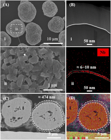 | ||
| Fig. 1 (A; i and ii) FE-SEM images of LNO-coated NMC811. (B) (i) FIB-TEM image and (ii) EDS spectrum of LNO-coated NMC811 (LNO@NMC). (C and D) FIB-SEM image and EDS mapping of BM-05 powder. | ||
The LPSCl SSE effectively fused with the surface of the bulk LNO@NMC particles to form an SSE@LNO@NMC multi-core–shell structure. The calculated thickness of the SSE@LNO@NMC particles (BM-05) was approximately 474 nm (Fig. 1C, D and S2†), which is close to the theoretically calculated value of 516 nm. The theoretical calculation is detailed in ESI (Fig. S2).† The bulk SSE@LNO@NMC powder was coated conformally onto the LNO@NMC particles, suggesting that fine agglomerated LPSCl particles were not present in the BM powder as shown in Fig. 2A(i and ii). Furthermore, the EDS results indicate that LPSCl was homogenously coated onto the CAM powder (Fig. 2B and S3†). The fusion of NMC and SSE particles was confirmed via XRD analysis. However, distinct SSE peaks were observed only in the BM-10 samples (Fig. 2C). The surface chemical compositions of the LNO@NMC and BM-05 powders were examined via X-ray photoelectron spectroscopy (XPS) analysis to further examine the SSE coating on BM-05, and the results are shown in Fig. 2D. Compared to the spectra of LNO@NMC, the survey spectra of BM-05 exhibited new peaks corresponding to Cl 2p, S 2p, and P 2p photoemissions, indicating that the surface of the LNO@NMC particles was completely coated with LPSCl. The structural homogeneity of the BM powders was verified via Rietveld refinement. The Rietveld refinement results for the BM-03, BM-05, and BM-10 samples indicate no significant changes in the crystal structure of the BM powders (Fig. S4†). Additional peaks corresponding to LPSCl were observed in the BM-10 sample owing to its high SSE content (Fig. S4D†). These distinct diffraction peaks indicate that LPSCl retained good crystallinity after the BM process. As ionic conductivity and tortuosity of the CAMs are critical parameters for enhanced rate performance, SSE coating onto the CAMs should have had a positive effect onto the impedance spectra. The calculated ionic conductivities of the LNO@NMC, BM-03, BM-05, and BM-10 composite cathodes were 5.3 × 10⁻⁵, 1.3 × 10⁻⁴, 1.8 × 10⁻⁴, and 1.9 × 10⁻⁴ mS cm−1, respectively (Fig. S5 and Table S1†). The ionic tortuosity factor (τion2) was calculated to account for the volume fraction of active material in the composite cathode. The values of τion2 for the LNO@NMC, BM-03, BM-05, and BM-10 composite cathodes were 6.7, 2.0, 1.8, and 1.6, respectively (Table S1†). Thus, the effective coating of SSE onto the LNO@NMC particles not only increased the ionic conductivity but also improved the ionic tortuosity in the composite cathode. The initial discharge capacities during the subsequent electrochemical performance were 150, 165, and 115 mA h g−1 at 0.3C for the BM-03-, BM-05- and BM-10-based ASSLBs, respectively (Fig. S6†). The lower discharge capacity for the BM-10-based ASSLB was attributed to the higher amount of SSE in the matrix, which can lead to lower electronic conductivity and consequently, decrease cathode utilization. Additionally, in Fig. S6,† the cycling was initiated directly at a C-rate of 0.3C without a prior lower-rate formation step. This approach may have resulted in lower discharge capacities for the BM-05 cell, as the lack of initial conditioning at a lower C-rate could lead to less optimal electro-chemo-mechanical formation within the cell.
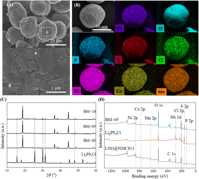 | ||
| Fig. 2 (A) FE-SEM images of 5 wt% SSE-coated LNO@NMC (BM-05). (B) EDS mapping of SSE@LNO@NMC powder. (C and D) XRD and XPS spectra of the Li6PS5Cl (SSE), LNO@NMC811, and BM-05 powders. | ||
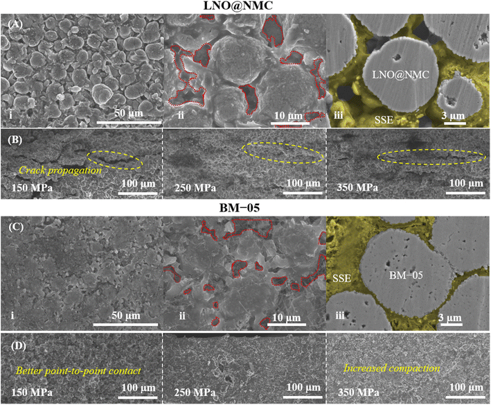
The mechanical effectiveness of the core–shell structure in the composite cathode was investigated via surface and cross-sectional examinations of the BM-05 and LNO@NMC composite pellets. The SEM images indicated a homogenously packed dense structure with uniform contact between the SSE and BM-05 particles, which is in contrast to the irregularly packed structure in the LNO@NMC composite cathode (Fig. 3A(i), (ii), C(i) and (ii)). Fig. 3A(iii) and C(iii) show the cross-sectional polished (CP) SEM images of the LNO@NMC- and BM-05-based cathode composites after uniaxial pressing. The number of surface and internal voids in the LNO@NMC-based composite cathode was large owing to the inadequate compaction of the SSE and NMC particles, primarily caused by the friction between hard CAM particles. In contrast, the hard core–soft shell structure of the BM-05 cathode yielded a denser composite, thereby establishing excellent ionic and electronic contact. Void formation (void area ≈ 27.41%) in the LNO@NMC-based composite can reduce the coverage of the active material with ionic and electronic conductors, resulting in increased interfacial resistance and subsequent degradation in electrochemical performance during high-rate operations. In contrast, the structure of the BM-05 cathode was highly dense (void area ≈ 8.43%), with intimate intra-particle contact between LNO@NCM and LPSCl, promoting enhanced coverage of active material particles. The effect of hard–hard and soft–soft contact hypothesis was studied further via cross-sectional examination of the BM-05- and LNO@NMC-based composite cathodes. Different fabrication pressures, namely 150, 250, and 350 MPa, were applied and the effect of removal of these stack pressures was examined. The residual stress induced between the particles at high pressures can, in general, generate cracks that propagate when the pressure is removed. At high void volumes, these cracks can delaminate the cathode from the SSE separator and lead to lower electrochemical performance. This behavior was observed for the LNO@NMC-based cathode, wherein large cracks were observed at 150 MPa, and these cracks remained at 250 and 350 MPa as well (Fig. 3D). In contrast, the cracks were almost negligible in the BM-05-based cathode. The soft-shell–soft-particle contact reduced the residual stresses due to plastic deformations “slippery compaction” and low void volume complemented this, thereby limiting the crack propagation (Fig. 3B). The measured packing density for the BM-05 composite cathode was 2.97 g cm−3, which corresponds to 90.3% of the theoretical packing density (3.27 g cm−3) and is 10% higher than that of the LNO@NMC composite cathode (2.63 g cm−3) (Fig. 4A). Thus, the increased compaction of BM-05 increased the packing density of the cathode composite and consequently, improved the point-to-point contact between the SSE and CAM particles.
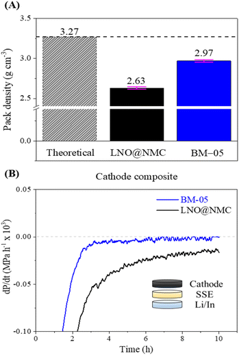 | ||
| Fig. 4 (A) Comparison between the packing densities of the LNO@NMC and BM-05 composite cathodes. (B) Rate of change in the stack pressure of the LNO@NMC and BM-05 composite cathodes at OCV. | ||
The electro-mechanical stability of the BM-05 composite cathode during cycling was examined via stack pressure measurement using a specialized custom-built load-cell assembly (Fig. S7A†). The BM-05 composite|SSE|Li/In cell and the bare LNO@NMC composite|SSE|Li/In cell were prepared in a manner similar to the cycling cells in this study. The stack pressure at 55 °C was measured at open circuit for 10 h for both cells to examine the change in the stack pressure. The initial stack pressure in both cells was 12.7 MPa, corresponding to the 5 N m (J) torque applied during cell assembly. As shown in Fig. S7B,† the stack pressure in the BM-05 cell decreased to 10.6 MPa (16.7% reduction) after 10 h, whereas that in the LNO@NMC cell decreased to 8.7 MPa (31.5% reduction). This change in the stack pressure at open circuit voltage (OCV) is primarily associated with physical deformations in the cathode, SE membrane, and Li/In metal. Li metal deformation accounts for more than 50% of the pressure change, with SSE's (separator) deformation being almost negligible.42 Consequently, the mechanical relaxation of the cathode has the most significant impact on the stack pressure change at open circuit after the Li metal. The BM-05 cell exhibited a lower decrease in the stack pressure and thus, a higher mechanical stability compared to the LNO@NMC cell owing to the better densification and low void volume at the cathode. This high mechanical stability can be attributed to the “slippery compaction” phenomenon of SSE and SSE@LNO@NMC particles during the fabrication process. This slippery compaction induces soft-shell SSE–SSE contact (similar to that when two rubber balls are pressed together) and promotes physical contact between the LNO@NMC particles through the facile deformation of SSE. This results in a dense ionic and electronic percolation structure. In contrast, this contact in LNO@NMC is mostly frictional and elastic, which limits the contact area and leads to poor compaction, resulting in subsequent delamination from the SSE separator. Results of differential electrochemical pressiometry further confirmed this phenomenon: the BM-05-based ASSLB reached equilibrium before 10 h of rest time, whereas the LNO@NMC-based ASSLB remained in the deformation stage (Fig. 4B). Moreover, because of the better densification and high ionic/electronic contact, the OCV remained stable at approximately 2.0 V throughout the rest time of 4 h (Fig. S7C†).
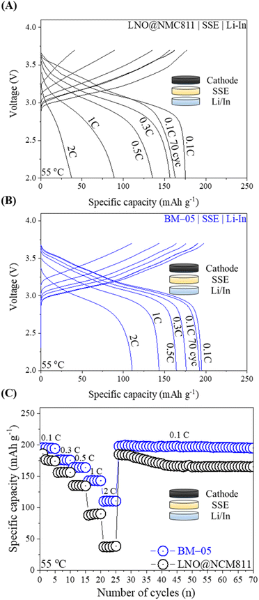
ASSLBs with a Li/In metal anode and an LPSCl SSE separator layer were fabricated to assess the electrochemical properties of both the bare LNO@NMC and BM-05 composite cathodes in a pressed cell configuration. During the test, the total active material content within the composite cathode was maintained at 75% and the loading level was set to 10 mg cm−2. Fig. 5A and B illustrate the galvanostatic charge–discharge profiles of the ASSLBs for the LNO@NMC and BM-05 composite cathodes at various current densities. The initial discharge capacity of the BM-05 cell at 0.1C was 197 mA h g−1, whereas that of the LNO@NMC-based cell was 175 mA h g−1. The enhanced initial discharge capacity of the BM-05 cell can be attributed to the high utilization of the active material particles in the BM-05 cathode composite. Furthermore, the BM-05 cell exhibited improved discharge capacities of 197, 176, 167, 144, and 112 mA h g−1 at 0.1, 0.3, 0.5, 1.0, and 2.0C, respectively, whereas the discharge capacities of the LNO@NMC cell were 176, 152, 141, 96, and 37 mA h g−1, respectively, at the same current rates (Fig. 5C).
This improved rate capability confirms the densely packed ionic and electronic percolation structure of the BM-05 composite cathode. After rate cycling, the cells were re-cycled at 0.1C to examine the capacity retention of the LNO@NMC and BM-05 cells. The capacity of the BM-05 cells after 70 cycles was >190 mA h g−1, whereas that of the LNO@NMC cell was 163 mA h g−1. This demonstrates that the core–shell architecture of BM-05 helped retain the inter-particle contact in the composite cathode even after cycling at higher current densities.
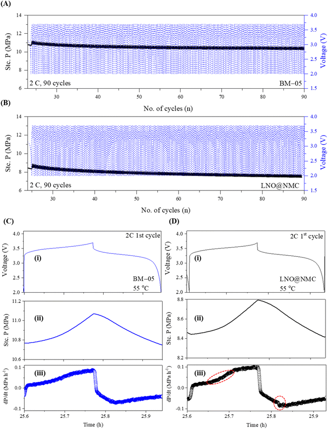
The stack pressure change behavior at high current cycling was examined by cycling the BM-05 and LNO@NMC-based ASSLBs for 90 cycles at 2C. Abrupt lithiation/delithiation at high current density can lead to poor CAM utilization due to poor densification and ionic/electronic contact in the initial cycles, resulting in a decrease in capacity retention.43 The stack pressure in BM-05-based ASSLB reached a stable value after 40 cycles owing to the high densification and mechanical stability at the composite cathode. In contrast, this stabilization in the LNO@NMC cell occurred much later (after 60 cycles). The stack pressure in LNO@NMC decreased continuously even after 90 cycles at 2C. However, the change in the stack pressure stabilized much faster in the BM-05 cell (Fig. 6a and B). Results of differential electrochemical pressiometry for the 1st cycles at 2C (Fig. 6C and D) indicated a sharp increase in the pressure for the LNO@NMC cell at 3.4 V (circled red) as compared to the BM-05 cell; similarly, a sharp decrease in the pressure was observed during discharging for the LNO@NMC cell (circled red). This demonstrates that the multi-core–shell architecture helped maintain the mechanical structure of the composite at higher current rates (it is important to note that the charge/discharge times at 2C for both cells are shorter than the typical duration. This is due to the specialized pressure-measuring setup, which is primarily designed to provide insights into the mechanical dynamics during cycling, specifically to observe and compare the behavior of pressure changes between the LNO@NMC and BM-05 cathodes. Therefore, these shorter cycle times should not be interpreted as an indication of the inherent performance of the cathode materials themselves, but rather as a result of the specific test conditions.).
Fig. 7A shows the extended galvanostatic cycling of the BM-05 and LNO@NMC cells at 2C for 1000 cycles. The discharge capacity of the BM-05 cell after 1000 cycles was high at 112 mA h g−1 (0.1C/1C, 76%), whereas that of the LNO@NMC cell was 74 mA h g−1 (0.1C/1C, 54%). During the initial cycles, frequent fluctuations in the capacity due to electrochemo-mechanical stabilization were observed for both cells. However, the BM-05 cell exhibited more stable cycling than the LNO@NMC cell.
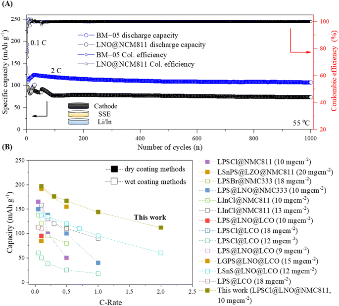 | ||
| Fig. 7 (A) Galvanostatic cycling of the bare LNO@NMC and BM-05-based cathode composite ASSLBs at 2C for 1000 cycles. (B) Comparison of the reported specific capacities at various current densities for wet- and dry-coated multi-core–shell cathode active materials for ASSLBs. The details can be found in Table S2†. | ||
The stable cyclability of the BM-05 cell observed during the initial cycles can be attributed to the lower stress relaxation resulting from the better compaction within the composite compared to that of the LNO@NMC cell. Hence, stable physical contact, combined with high compaction and low void volume in the cathode composite, enhanced the Li-ion kinetics and reduced the interfacial resistance, thereby increasing the discharge capacity at high current densities. This phenomenon is further evident in the Nyquist plots of the bare LNO@NMC and BM-05 LPSCl@LNO@NMC composite cells obtained via electrochemical impedance spectroscopy (EIS) before and after cycling (1000 cycles at 2C) (Fig. S8†).44,45 The interfacial resistance (Ri) values of the LNO@NMC and BM-05 cells before cycling were 31.1 and 36.7 Ω, respectively. The interfacial resistance as well as the charge-transfer resistance (Rct) of both cells increased after cycling. The Ri and Rct values of BM-05 were 109 and 236 Ω, respectively, whereas those of the LNO@NMC cell were 148 and 291 Ω, respectively. These spectroscopic data confirm that the ionic conduction pathway of the BM-05 LPSCl@LNO@NMC composite cathodes after long cycling was better preserved compared to that of bare LNO@NMC, leading to an increase in electrochemical performance. To the best of our knowledge, as shown in Fig. 7B, the cathode utilization and rate capability of this engineered composite cathode are the highest among the ASSLBs with LPSCl SSE-coated cathode.
Conclusions
In summary, we successfully prepared high-performance multi-core–shell powders based on argyrodite sulfide solid electrolyte and LNO@NMC811 powders using a dry, airtight BM technique. The ASSLB cell with the 5% LPSCl-coated 13 μm LNO@NMC811 multi-core–shell powders in the composite cathode exhibited significantly enhanced electrochemical performance, including improved cathode utilization (reversible capacity), rate capability, and cyclability. This improvement can be attributed to the low void volume and enhanced ionic and electronic percolation in the cathode composite facilitated by slippery compaction. These findings represent a significant step towards the development of composite cathodes with high energy density, high-rate performance, and long cycle life for ASSLBs, and contribute to accelerating the commercialization of ASSLBs.Data availability
The dataset associated with this study includes raw data for long-term charge–discharge cycling (Fig. 5C and 7A). These data support the findings of the study titled “Unraveling electrochemo-mechanical aspects of core–shell composite cathode for sulfide based all-solid-state batteries.”Author contributions
The manuscript was written with contributions from all the authors. All the authors approved the final version of the manuscript.Conflicts of interest
There are no conflicts to declare.Acknowledgements
This research was partly supported by the Korea Electrotechnology Research Institute (KERI) Primary Research Program (No. 24A01017) through the National Research Council of Science and Technology (NST) funded by the Ministry of Science and ICT (MSIT, Korea) and by the Technology Innovation Program (20009957) funded by the Ministry of Trade, Industry, and Energy (MOTIE, Korea). This work was also supported by the National Research Foundation of Korea (NRF) grant funded by the Korean government (MSIT) (RS-2024-00353531). The work by E. L. was supported by the Vehicle Technologies Office of the U.S. Department of Energy.References
- J. Lau, R. H. DeBlock, D. M. Butts, D. S. Ashby, C. S. Choi and B. S. Dunn, Adv. Energy Mater., 2018, 8, 1800933 CrossRef.
- D. Lee, H. Lee, T. Song and U. Paik, Adv. Energy Mater., 2022, 12, 2200948 CrossRef CAS.
- Y.-G. Lee, S. Fujiki, C. Jung, N. Suzuki, N. Yashiro, R. Omoda, D.-S. Ko, T. Shiratsuchi, T. Sugimoto, S. Ryu, J. H. Ku, T. Watanabe, Y. Park, Y. Aihara, D. Im and I. T. Han, Nat. Energy, 2020, 5, 299 CrossRef CAS.
- K. J. Takada, J. Power Sources, 2018, 394, 74 CrossRef CAS.
- Z. Zhang, Y. Shao, B. Lotsch, Y. S. Hu, H. Li, J. Janek, L. F. Nazar, C. W. Nan, J. Maier, M. Armand and L. Chen, Energy Environ. Sci., 2018, 11, 1945 RSC.
- Y. Wu, S. Wang, H. Li, L. Chen and F. Wu, InfoMat, 2021, 3, 827 CrossRef CAS.
- M. Ali, C. H. Doh, Y. J. Lee, B. G. Kim, J. W. Park, J. Park, G. Park, W. J. Lee, S. M. Lee and Y. C. Ha, Energy Technol., 2021, 9, 2001096 CrossRef CAS.
- S. Chen, D. Xie, G. Liu, J. P. Mwizerwa, Q. Zhang, Y. Zhao, X. Xu and X. Yao, Energy Storage Mater., 2018, 14, 58 CrossRef.
- C. Yu, L. van Eijck, S. Ganapathy and M. Wagemaker, Electrochim. Acta, 2016, 215, 93 CrossRef CAS.
- S. Wang, Y. Zhang, X. Zhang, T. Liu, Y.-H. Lin, Y. Shen, L. Li and C.-W. Nan, ACS Appl. Mater. Interfaces, 2018, 10, 42279 CrossRef CAS PubMed.
- X. Zeng, M. Li, D. Abd El-Hady, W. Alshitari, A. S. Al-Bogami, J. Lu and K. Amine, Adv. Energy Mater., 2019, 9, 1900161 CrossRef.
- X. Li, W. Peng, R. Tian, D. Song, Z. Wang, H. Zhang, L. Zhu and L. Zhang, Electrochim. Acta, 2020, 363, 137185 CrossRef CAS.
- W. D. Richards, L. J. Miara, Y. Wang, J. C. Kim and G. Ceder, Chem. Mater., 2016, 28, 266 CrossRef CAS.
- J. Haruyama, K. Sodeyama, L. Han, K. Takada and Y. Tateyama, Chem. Mater., 2014, 26, 4248 CrossRef CAS.
- T. Shi, Y. Q. Zhang, Q. Tu, Y. Wang, M. C. Scott and G. J. Ceder, J. Mater. Chem. A, 2020, 8, 17399 RSC.
- N. Ohta, K. Takada, I. Sakaguchi, L. Zhang, R. Ma, K. Fukuda, M. Osada and T. Sasaki, Electrochem. Commun., 2007, 9, 1486 CrossRef CAS.
- S. Ito, S. Fujiki, T. Yamada, Y. Aihara, Y. Park, T. Y. Kim, S. W. Baek, J. M. Lee, S. Doo and N. J. Machida, J. Power Sources, 2014, 248, 943 CrossRef CAS.
- J. H. Woo, J. E. Trevey, A. S. Cavanagh, Y. S. Choi, S. C. Kim, S. M. George, K. H. Oh and S.-H. Lee, J. Electrochem. Soc., 2012, 159, A1120 CrossRef CAS.
- K. Takada, N. Ohta, L. Zhang, K. Fukuda, I. Sakaguchi, R. Ma, M. Osada and T. Sasaki, Solid State Ionics, 2008, 179, 1333 CrossRef CAS.
- S. P. Culver, R. Koerver, W. G. Zeier and J. Janek, Adv. Energy Mater., 2019, 9, 1900626 CrossRef.
- Y. Ma, R. Zhang, Y. Ma, T. Diemant, Y. Tang, S. Payandeh, D. Goonetilleke, D. Kitsche, X. Liu, J. Lin, A. Kondrakov and T. Brezesinski, Chem. Mater., 2024, 36, 2588–2598 CrossRef CAS.
- S. Choi, M. Jeon, J. Ahn, W. D. Jung, S. M. Choi, J.-S. Kim, J. Lim, Y. Jang, H. Jung, J. Lee, B. Sang and H. Kim, ACS Appl. Mater. Interfaces, 2018, 10, 23740 CrossRef CAS PubMed.
- Y. J. Nam, D. Y. Oh, S. H. Jung and Y. S. Jung, J. Power Sources, 2018, 375, 93 CrossRef CAS.
- D. Hlushkou, A. E. Reising, N. Kaiser, S. Spannenberger, S. Schlabach, Y. Kato, B. Roling and U. Tallarek, J. Power Sources, 2018, 396, 363 CrossRef CAS.
- D. H. Kim, D. Y. Oh, K. H. Park, Y. E. Choi, Y. J. Nam, H. A. Lee, S. M. Lee and Y. S. Jung, Nano Lett., 2017, 17, 3013 CrossRef CAS PubMed.
- T. Shi, Q. Tu, Y. Tian, Y. Xiao, L. J. Miara, O. Kononova and G. Ceder, Adv. Energy Mater., 2020, 10, 1902881 CrossRef CAS.
- B. S. Vishnugopi, E. Kazyak, J. A. Lewis, J. Nanda, M. T. McDowell, N. P. Dasgupta and P. P. Mukherjee, ACS Energy Lett., 2021, 6, 3734–3749 CrossRef CAS.
- S. Brutti, G. Greco, P. Reale and S. Panero, Electrochim. Acta, 2013, 106, 483–493 CrossRef CAS.
- P. Minnmann, F. Strauss, A. Bielefeld, R. Ruess, P. Adelhelm, S. Burkhardt, S. L. Dreyer, E. Trevisanello, H. Ehrenberg, T. Brezesinski, F. H. Richter and J. Janek, Adv. Energy Mater., 2022, 12, 2201425 CrossRef CAS.
- L. De Biasi, A. O. Kondrakov, H. Geßwein, T. Brezesinski, P. Hartmann and J. Janek, J. Phys. Chem. C, 2017, 121, 26163–26171 CrossRef CAS.
- M.-J. Kim, J.-W. Park, B. G. Kim, Y.-J. Lee, Y.-C. Ha, S.-M. Lee and K.-J. Baeg, Sci. Rep., 2020, 10, 11923 CrossRef CAS PubMed.
- N. C. Rosero-Navarro, A. Miura and K. Tadanaga, J. Power Sources, 2018, 396, 33 CrossRef CAS.
- S. Yubuchi, S. Teragawa, K. Aso, K. Tadanaga, A. Hayashi and M. Tatsumisago, J. Power Sources, 2015, 293, 941 CrossRef CAS.
- S. Teragawa, K. Aso, K. Tadanaga, A. Hayashi and M. Tatsumisago, J. Power Sources, 2014, 248, 939 CrossRef CAS.
- M. Ali, S. C. Han, H. Park, Y. Lee, B. G. Kim, J.-W. Park, J. Park, J.-H. Choi and Y.-C. Ha, J. Mater. Chem. A, 2022, 10, 25471 RSC.
- H. Nakamura, T. Kawaguchi, T. Masuyama, A. Sakuda, T. Saito, K. Kuratani, S. Ohsaki and S. Watano, J. Power Sources, 2020, 448, 227579 CrossRef CAS.
- Y. Park, J. H. Chang, G. Oh, A.-Y. Kim, H. Chang, M. Uenal, S. Nam and O. Kwon, Small, 2024, 20, 2305758 CrossRef CAS PubMed.
- Y. Ito, M. Otoyama, A. Hayashi, T. Ohtomo and M. Tatsumisago, J. Power Sources, 2017, 360, 328–335 CrossRef CAS.
- A. Sakuda, A. Hayashi, T. Ohtomo, S. Hama and M. Tatsumisago, J. Power Sources, 2011, 196, 6735–6741 CrossRef CAS.
- J. Kim, M. J. Kim, J. Kim, J. W. Lee, J. Park, S. E. Wang, S. Lee, Y. C. Kang, U. Paik, D. S. Jung and T. Song, Adv. Funct. Mater., 2023, 33, 2211355 CrossRef CAS.
- L. Zheng, C. Wei, M. D. L. Garayt, J. MacInnis and M. N. Obrovac, J. Electrochem. Soc., 2019, 166, A2924 CrossRef CAS.
- C. Lee, S. Y. Han, J. A. Lewis, P. P. Shetty, D. Yeh, Y. Liu, E. Klein, H.-W. Lee and M. T. McDowell, ACS Energy Lett., 2021, 6, 3261 CrossRef CAS.
- J. Gu, Z. Liang, J. Shi and Y. Yang, Adv. Energy Mater., 2023, 13, 2203153 CrossRef CAS.
- W. Choi, H. C. Shin, J. M. Kim, J. Y. Choi and W. S. Yoon, J. Electrochem. Sci. Technol., 2020, 11, 1 CrossRef CAS.
- N. Togasaki, A. Nakao, T. Tanaka, U. Harada, H. Onish, H. Yasuda, S. Kobayashi, F. Maeda and T. Osaka, J. Electrochem. Soc., 2023, 170, 050519 CrossRef CAS.
Footnotes |
| † Electronic supplementary information (ESI) available: Experimental details of multi-core–shell LPSCl@LNO@NMC powder preparation, material characterization (FE-SEM, XRD, XPS, FIB-EDS, HAADF-TEM and CP-SEM-EDS), and electrochemical characterization (EIS and galvanostatic charge/discharge). Additional results and information include the optimization of the BM process, cell configuration and performance of the composite cathodes, and characterization of LPSCl@LNO@NMC powders and LPSCl solid electrolytes. See DOI: https://doi.org/10.1039/d4ta04063e |
| ‡ These authors contributed equally. |
| This journal is © The Royal Society of Chemistry 2024 |

