
Realizing high-stability anodes for rechargeable magnesium batteries via in situ-formed nanoporous Bi and nanosized Sn†
Dachong
Gu
a,
Yuan
Yuan
 *abc,
Xianhao
Peng
a,
Dajian
Li
a,
Liang
Wu
a,
Guangsheng
Huang
a,
Jingfeng
Wang
a and
Fusheng
Pan
ab
*abc,
Xianhao
Peng
a,
Dajian
Li
a,
Liang
Wu
a,
Guangsheng
Huang
a,
Jingfeng
Wang
a and
Fusheng
Pan
ab
aNational Engineering Research Center for Magnesium Alloys, College of Materials Science and Engineering, Chongqing University, Chongqing, 400000, China. E-mail: yuanyuan17@cqu.edu.cn; yuan.yuan.er@gmail.com
bChongqing Institute of New Energy Storage Materials and Equipment, Chongqing, 401122, China
cSchool of Materials Science and Engineering, Central South University, Changsha, 410083, China
First published on 3rd September 2024
Abstract
Rechargeable magnesium batteries (RMBs) are regarded as potential next-generation energy storage technologies, thanks to their high theoretical specific capacity and abundance of magnesium resources. However, magnesium anodes tend to form passivating surface films, which hinder the reversible transport of Mg2+ ions and narrow the selection of suitable electrolytes. Herein, the Bi–Sn alloy loaded with SnO2 (Bi–Sn@SnO2) is synthesized to be the anode for RMBs and improve diffusion kinetics of Mg2+ ions. The Bi–Sn@SnO2 anode delivers a reversible capacity of 314 mA h g−1 at 50 mA g−1. In addition, the Bi–Sn@SnO2 anode exhibits high rate performance (297 mA h g−1 at 500 mA g−1) and long cycle life (148 mA h g−1 at 1 A g−1 after 300 cycles) due to the in situ formation of nanoporous Bi and nanosized Sn by the synergistic effect of Bi–Sn phase separation, defects and the Mg2+ insertion/extraction reaction. The loading of SnO2 on the Bi–Sn alloy surface can restrict the growth of alloy particles and reduce the decomposition of electrolytes. Noticeably, the Bi–Sn@SnO2 anode shows good compatibility with the chloride-free Mg(TFSI)2/G2 electrolyte.
1 Introduction
The demand for battery storage systems in terms of low cost, high safety and high energy density is increasing with the development of intermittent energy storage, electric vehicles and portable devices. Lithium-ion batteries are facing a cost rise due to the limited Li and Co resources and safety issues, especially in large-scale applications.1–6 Recently, as an alternative to lithium-ion batteries, RMBs have attracted much attention owing to their high volumetric capacity (3833 mA h cm−3), low cost and fewer dendrite problems.7–12 However, the poor compatibility between the conventional electrolyte components (magnesium salts and solvents) and the Mg metal anode still hinders the development of the RMBs. The reduction products of conventional electrolytes on the Mg surface cannot conduct Mg2+ ions, hence blocking the electrochemical reaction.13–15 Some electrolytes have been applied to avoid Mg anode–electrolyte passivation reactions, which involve halide-ion-containing electrolytes with high corrosiveness and poor anodic stability16–19 and borohydride-based electrolytes20–22 with a complex preparation process.Since the alloy electrode potential is around 0.1–0.5 V higher than that of Mg metal, using alloy-type anodes may result in better compatibility with simple salt electrolytes, which is considered to be another feasible strategy to bypass the passivation problem.23 Currently, Bi and Bi-based alloys are very attractive as anodes for RMBs because of the relatively high capacity (385 mA h g−1 and 3783 mA h cm−3) based on the alloying reaction 3Mg2+ + 2Bi + 6e− ![[left over right harpoons]](https://www.rsc.org/images/entities/char_21cb.gif) Mg3Bi2 and fast Mg2+ kinetics.24–26 The electrochemical activity of electrodeposited Bi anodes with the Mg(TFSI)2/AN electrolytes was first demonstrated in a three-electrode cell in 2012.27 Meng et al.28 constructed a Mg3Bi2//S battery prototype with high specific capacity and long-cycle life (400 mA h g−1 at a rate of C/2 after 30 cycles) in Mg(TFSI)2/DME electrolytes. Notably, the magnesiation and demagnesiation of Bi anodes will lead to the detachment of Bi fragment from the Bi electrodes and capacity loss due to the 100% volume change.29 Wang et al.30 prepared Bi nanoparticles encapsulated in nitrogen-doped carbon (Bi@NC) through the carbonisation of Bi2O2CO3@PDA. The specific capacity of Bi@NC was observed to be 289.4 mA h g−1 in Mg(PFTB)2 electrolyte at 200 mA g−1, with a capacity retention of 74.7% after 300 cycles. Structural control (such as Bi nanocrystals,31 mesoporous Bi32 and Bi nanotubes33) and alloying (Bi–Sn,34–36 Bi–Sb,37 Bi–Pb,38 Bi–Sb–Sn,39etc.) strategies are used to mitigate the huge volume change, improve the cycling stability and increase the specific capacity. In addition, Bi-based alloys have been employed in the fabrication of magnesium anode interfacial protection layers based on their rapid Mg2+ ion diffusion kinetics. Chai et al.40 employed the electrodeposition method to prepare a Mg–Sn–Bi ternary alloy interphase layer on Mg foil (Mg–Sn–Bi@Mg). The Mg–Sn–Bi@Mg anode facilitates the rapid deposition and stripping of Mg2+, exhibiting a low overpotential of 39.4 mV and a cycle life exceeding 2000 hours.
Mg3Bi2 and fast Mg2+ kinetics.24–26 The electrochemical activity of electrodeposited Bi anodes with the Mg(TFSI)2/AN electrolytes was first demonstrated in a three-electrode cell in 2012.27 Meng et al.28 constructed a Mg3Bi2//S battery prototype with high specific capacity and long-cycle life (400 mA h g−1 at a rate of C/2 after 30 cycles) in Mg(TFSI)2/DME electrolytes. Notably, the magnesiation and demagnesiation of Bi anodes will lead to the detachment of Bi fragment from the Bi electrodes and capacity loss due to the 100% volume change.29 Wang et al.30 prepared Bi nanoparticles encapsulated in nitrogen-doped carbon (Bi@NC) through the carbonisation of Bi2O2CO3@PDA. The specific capacity of Bi@NC was observed to be 289.4 mA h g−1 in Mg(PFTB)2 electrolyte at 200 mA g−1, with a capacity retention of 74.7% after 300 cycles. Structural control (such as Bi nanocrystals,31 mesoporous Bi32 and Bi nanotubes33) and alloying (Bi–Sn,34–36 Bi–Sb,37 Bi–Pb,38 Bi–Sb–Sn,39etc.) strategies are used to mitigate the huge volume change, improve the cycling stability and increase the specific capacity. In addition, Bi-based alloys have been employed in the fabrication of magnesium anode interfacial protection layers based on their rapid Mg2+ ion diffusion kinetics. Chai et al.40 employed the electrodeposition method to prepare a Mg–Sn–Bi ternary alloy interphase layer on Mg foil (Mg–Sn–Bi@Mg). The Mg–Sn–Bi@Mg anode facilitates the rapid deposition and stripping of Mg2+, exhibiting a low overpotential of 39.4 mV and a cycle life exceeding 2000 hours.
Sn alloying with Mg (2Mg2+ + Sn + 4e− → Mg2Sn) leads to a high theoretical capacity of 903 mA h g−1 and a low plateau of 0.2 V (vs. Mg2+/Mg).41 Earlier studies have demonstrated sluggish Mg2+ ion kinetics in bulk Sn. Additionally, the Sn anode experiences a 214% volume change in cycling, resulting in poor electrochemical performance.42,43 Parent et al.44 pointed out that the particle size of the Sn anode should be <40 nm for excellent reversible Mg-storage and they prepared SnSb/graphene composites to form nano-Sn in situ which can deliver a reversible capacity of ∼470 mA h g−1 (calculated by using the pure-Sn nanodomains). However, due to the low reactivity of Sb, the mass of the electrode increases and the energy density of the battery decreases.
In the present work, we propose a facile thermo-reduction (deoxygenation) method to prepare a Bi–Sn alloy loaded with SnO2 (Bi–Sn@SnO2) anode, which is suitable for large-scale production. The SnO2 particles can limit the growth of Bi–Sn alloy particles and can reduce the decomposition of the electrolyte according to the ex situ XPS analysis. Additionally, defects in Bi–Sn@SnO2 can cause lattice distortion and internal stresses to form amorphous Mg–Bi. The obtained Bi–Sn@SnO2 anode delivers a high reversible capacity of 148 mA h g−1 after 300 cycles at a current density of 1 A g−1. The exceptional performance is attributed to nanoporous Bi and nanosized Sn formed in situ in the presence of defects during cycling, effectively alleviating volume change and enhancing alloy anode reactivity.
2 Results and discussion
2.1 Microstructures and components
The synthesis process of the Bi–Sn@SnO2 (BSS-600) alloy material is briefly exhibited in Fig. 1a. Firstly, Bi2Sn2O7 (BSO) was obtained by the hydrothermal reaction of Bi(NO3)3·5H2O and Na2SnO3·3H2O under alkaline conditions. The obtained BSO emphasizes the interpenetration of SnO6 octahedral sublattices and Bi2O tetrahedral sublattices (Fig. 1b). Secondly, BSO is annealed under an Ar and H2 atmosphere for 3 h. XRD patterns of the as-prepared samples are shown in Fig. 1c, and the strong diffraction peaks presented at 28.8°, 33.4°, 47.9° and 56.9° can be assigned to the γ-Bi2Sn2O7 phase. The broadened peaks of BSO can be attributed to the nanosized particles. To compare the diffraction peaks of the larger BSO particles with those of pristine BSO, the latter was held at 800 °C for 3 hours under an Ar gas flow. The size of the obtained BSO is increased to about 200 nm without a phase transition, proving that BSO has high thermal stability. Simultaneously, the corresponding characteristic peaks of BSO in the XRD pattern become sharper, which demonstrates that the wide peaks of pristine BSO are related to the particle size (Fig. S1†). After annealing in an Ar/H2 atmosphere at 400 °C and 500 °C, the peak belonging to BSO disappeared and an obvious Bi phase can be observed with major peaks at 27.3°, 38.1° and 39.7°. As the reaction temperature increases, the intensity of the peaks corresponding to the Sn phase (30.6° and 32.0°) increases gradually. The broad characteristic peaks of BSS-400 and BSS-500 at 26.6° and 33.9° corresponding to SnO2 can be related to the low crystallinity of SnOx mixed phases (0 < x < 3.5). When the temperature further increased to 600 °C, the obtained product is composed of the Bi phase, Sn phase and SnO2 phase owing to more complete thermal reduction. It can be concluded that the thermal reduction reaction of BSO can be summarized as follows:| Bi2Sn2O7 + H2 → Bi + H2O + SnOx, (0 < x < 3.5) | (1) |
| SnOx + H2 → Sn + H2O, (0 < x < 3.5) | (2) |
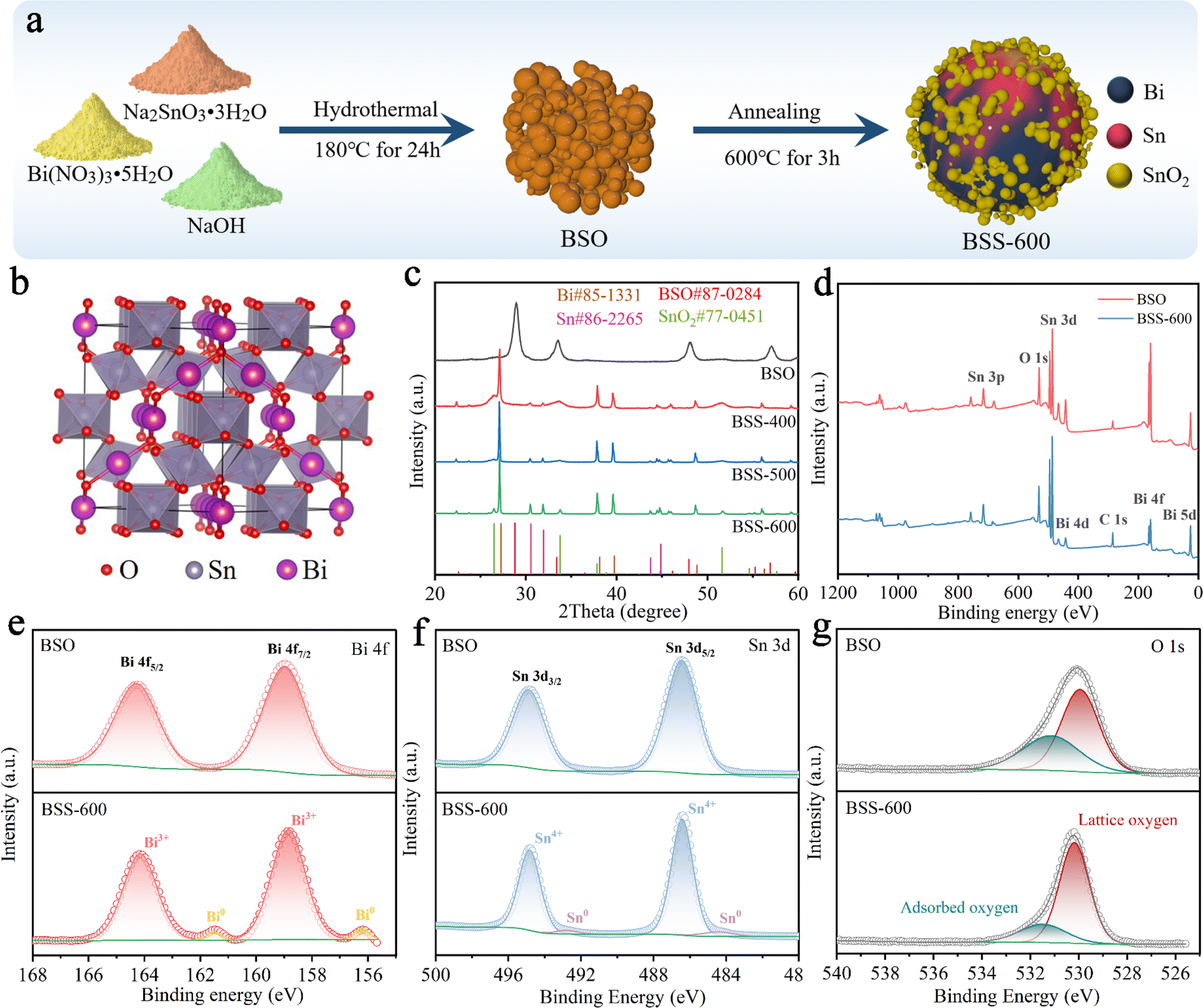 | ||
| Fig. 1 (a) Schematic diagram of the preparation process of BSS-600. (b) Crystal structure of BSO. (c) XRD patterns of BSO, BSS-400, BSS-500 and BSS-600. (d) XPS full spectrum of BSO and BSS-600 and high-resolution (e) Bi 4f, (f) Sn 3d, and (g) O 1s XPS spectra. | ||
X-ray photoelectron spectroscopy (XPS) is utilised for the analysis of the chemical status of the BSO and BSS-600 samples. Fig. 1d presents the overall elemental spectrum, which reveals signals from the Bi, Sn, O and C elements. In comparison to BSO, the Sn and O peaks of BSS-600 remain consistent, while the Bi peaks are observed to be weaker. This phenomenon can be attributed to the partial coverage of Bi by SnO2 in the BSS-600 sample, which has resulted in a reduction in the peak intensity of Bi. The peak signals observed at 158.9 eV and 164.3 eV are attributed to the Bi 4f7/2 and Bi 4f5/2 states of Bi2O3, respectively (Fig. 1e). The peaks at 486.4 eV and 494.7 eV correspond to the binding energies of Sn 3d5/2 and Sn 3d3/2 states of SnO2 (Fig. 1f). The XPS signals of pure Bi (156.2 eV) and Sn (484.4 eV) are demonstrated in the BSS-600 sample in comparison to the BSO sample. However, the binding energy of Bi and Sn is lower than their equilibrium binding energy (157.0 eV for Bi and 485.0 eV for Sn). This observation demonstrates an increase in the electron density of Bi and Sn, which can be attributed to the generation of defects during the thermal reduction process (deoxygenation process). Oxygen species were also detected by O 1s XPS, as shown in Fig. 1g. Two typical XPS peaks at ∼530.2 and 531.5 eV can be attributed to lattice oxygen and adsorbed oxygen species, respectively.45
According to the SEM image, the BSO particles aggregate to form a porous bulk material (Fig. 2a). The transmission electron microscopy (TEM) image of BSO is illustrated in Fig. S2.† The BSO bulk is formed by the connection of the nanoparticles, which are approximately 40 nm in size. The morphology of the obtained particles at different annealing temperatures was characterized. At 400 °C and 500 °C, the thermal reduction products of BSO show a mixture of bulks and alloy particles due to the limited reduction reaction (Fig. 2b and c). As the reaction temperature increased to 600 °C, microspheres (2–5 μm) with irregular particles on the surface were obtained (BSS-600), which are believed to be bismuth–tin alloy spheres loaded with SnO2 on the surface. When the annealing time is halved to 1.5 hours, the alloy exhibits a relatively elevated SnO2 content and a diminished Sn concentration, accompanied by the emergence of micropores on the surface of the alloy particles (Fig. S3†). This observation indicates that deoxygenation of BSO may result in the preferential formation of Bi and that incomplete thermal reduction of SnO2 may restrict the flow of molten Bi-metal and form micropores on the alloy surface. No SnO2 was detected in the obtained products when the annealing temperature of BSO was increased to 650 °C, based on the SEM image and XRD analysis (Fig. S4†). Meanwhile, the size of the alloy particles increased to around 50 μm, suggesting that SnO2 could limit the growth of the alloy particles during the cooling process of preparation. The aforementioned investigation of process time and temperature also indicates that annealing at 600 °C for 3 hours is an appropriate method.
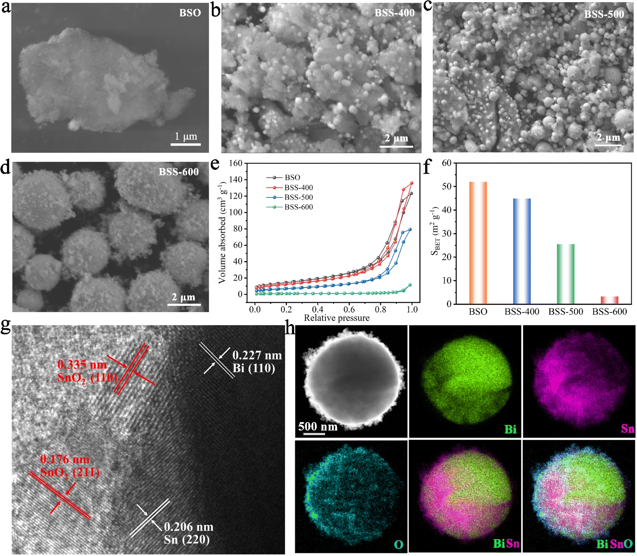 | ||
| Fig. 2 (a–d) SEM images of BSO, BSS-400, BSS-500 and BSS-600; (e and f) N2 adsorption–desorption isotherms and BET surface areas. (f) HRTEM-image of BSS-600. (g and h) HADDF-STEM image of BSS-600 and the corresponding elemental color mapping for Bi, Sn, and O. | ||
The N2 adsorption and desorption curves of BSO, BSS-400 and BSS-500 are typical IV isotherms, as shown in Fig. 2e. BSO is a porous block stacked by particles with a high Brunauer–Emmett–Teller (BET) surface area of 52.0 m2 g−1 (Fig. 2f and Table S1†). The N2 adsorption–desorption isotherm of BSS-600 shows no obvious H3 hysteresis loop and the specific surface area is measured to be 3.3 m2 g−1. Both the larger pore size and BET surface of BSS-400 and BSS-500 indicate the incomplete reaction of BSO after the thermal reduction treatment. The high-angle annular dark field (HAADF) image and the corresponding elemental mapping images (Fig. 2h) indicate the Bi–Sn core and the uniform distribution of Sn and O on its surface. The HRTEM image of BSS-600 shows lattice spacings measured for the particles on the alloy surface to be approximately 0.335 nm and 0.176 nm in Fig. 2g, corresponding to the (110) and (211) lattice planes of SnO2. The interplanar spacings of 0.227 nm and 0.206 nm for the core can be indexed to the (110) and (220) lattice planes of Bi and Sn. The above results additionally demonstrate the structure of the Bi–Sn alloy loaded with SnO2 particles.
The results of SEM and elemental mapping of the pristine BSS-600 electrode are shown in Fig. 3a. In the BSS-600 alloy material, Bi-dominated regions can be distinguished from Sn-dominated regions according to the elemental mapping. Since the melting point of Bi is 271.4 °C, slightly higher than that of Sn (231.9 °C), the Bi phase nucleates and grows during the annealing process and separates from the Sn phase. After the first three cycles, the BSS-600 electrode forms in situ porous Bi and Sn as in the SEM image and elemental mappings of the activated BSS-600 electrode (Fig. 3b), which can be associated with the irreversible volume expansion in Mg2+ embedding and subsequent Mg2+ stripping, as well as the presence of defects. The formation of the porous alloy enhances the electrode's specific surface area, which is more conducive to electrochemical reactions. The huge changes in the morphology of the BSS-600 electrodes reflect the presence of large internal stresses during Mg2+ ion intercalation/extraction. Following 20 cycles, the porous alloy undergoes further nanosizing to form a nanoporous alloy, which has been proven to be advantageous in increasing the contact surface area between the anode and electrolyte and shortening the diffusion path of Mg2+ ions. This process can facilitate the improvement of electrode performance and accommodate internal stresses, ensuring a stable cycling capacity. The elemental mappings display a more pronounced Bi signal and a partially overlapping Sn signal, which indicates the combination of nanoporous Bi and nano-Sn. The lattice spacings of the nanoporous alloy are measured to be approximately 0.328 nm and 0.376 nm (Fig. 3d), which correspond to the (012) and (101) lattice planes of Bi. The interplanar spacing of 0.326 nm can be indexed to the (012) lattice plane and the major peak at 27.3° of Bi. It is worth noting that a few defects were identified in larger grains, which can be associated with the formation of vacancies during the deoxygenation process. The continuous nanoporous alloy can be believed to be nanoporous Bi. Significant variations in particle size, from ∼5 μm in pristine BSS-600 to ∼50 nm in the cycled BSS-600 can be attributed to phase separation, defects and the volume change in Mg2+ embedding/stripping. The SEM images and corresponding elemental mappings (Fig. 3 and S5†) indicate that nanosized Sn rather than nanoporous Sn is obtained. The structural differences between Bi and Sn can be attributed to the magnitude of the volume change that occurs during the embedding and stripping of Mg2+. In comparison to the 100% volume change during Bi magnesiation, the 214% volume change during Sn magnesiation can be excessive for the formation of a continuous nanoporous alloy structure.
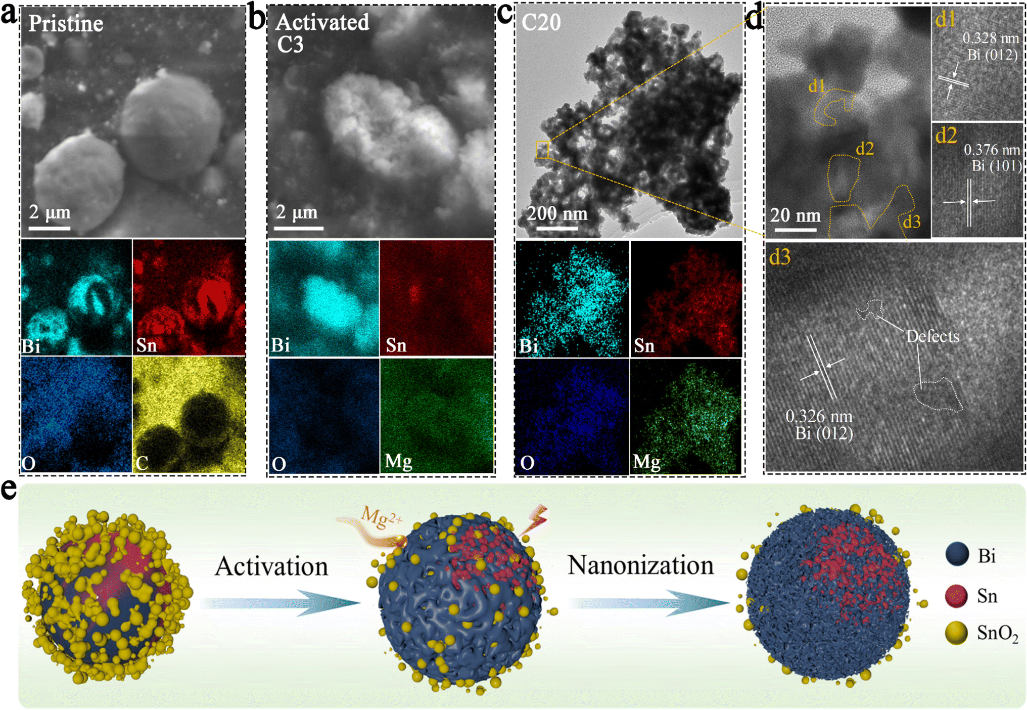 | ||
| Fig. 3 SEM images and elemental mappings of the (a) pristine BSS-600 electrode and (b) activated BSS-600 electrode. (c) TEM image and elemental mappings, and (d) HRTEM image of the BSS-600 electrode after the 20th charge. (e) Schematic illustration of morphological evolution of the BSS-600 electrode during cycles. | ||
2.2 Electrochemical performance and kinetic analyses
The cycling performance of as-prepared samples was tested at a current density of 50 mA g−1. The two initial cycles demonstrated obvious irreversible capacity in the first-cycle reactions for the BSO, BSS-400, and BSS-500 samples. For the BSO (Bi2Sn2O7) sample, a capacity of up to 958 mA h g−1 in the initial discharge decayed rapidly in the subsequent discharges as shown in Fig. 4a. Additionally, the 0.8–0.2 eV plateau observed in the initial discharge curve disappeared in the subsequent discharge (Fig. S6†). It can be assumed that the irreversible capacity loss and low stability observed in the BSO sample without thermal reduction (deoxygenation) are related to the formation of MgO (one of the components of the passivation film), which impedes the reversible insertion/extraction of Mg2+ ions. For the BSS-400 and BSS-500 samples, the initial capacity of the BSS-400 and BSS-500 electrodes was 185 and 216 mA h g−1, respectively, which subsequently decreased to 125 and 180 mA h g−1 during the 2nd discharge (Fig. 4a). The corresponding charge/discharge curves for the two initial cycles are shown in Fig. 4b. The sloping platform from 0.6–0.1 V is observed at the first cycle, which can be related to the irreversible reaction of SnOx (one of the phase components of BSS-400 and BSS-500 samples based on the XRD analysis above, 0 < x < 3.5) and lead to irreversible capacity loss. For the BSS-600 sample, the capacity decay behavior is not observed. In the initial discharge of the BSS-600 electrode, the voltage drops to ∼20 mV and then increases again (Fig. 4b). The characteristic potential drop during the initial discharge is also observed in other alloy anodes46,47 for RMBs, which is related to the adsorption and aggregation of Mg2+ ions on the surface of alloy particles. To further investigate the first cycle, GITT curves of the as-prepared samples (Fig. S7†) were obtained at 20 mA g−1. The GITT curves show the sloping discharge plateau at 0.8–0.2 V in BSO, BSS-400 and BSS-500 samples, which might be related to SnOx + Mg2+ → MgySnO2. The demagnesiation of MgySnO2 occurs during charging at 20 mA g−1 (Fig. S7†), not at 50 mA g−1 (Fig. 4b), which suggests that the reaction has kinetics limitations. The GITT curve of the BSS-600 electrode exhibits two voltage plateaus related to the magnesiation reactions of Bi and Sn without the plateau reaction of SnO2 with Mg2+ ions, indicating that SnO2 can be considered an inactive material.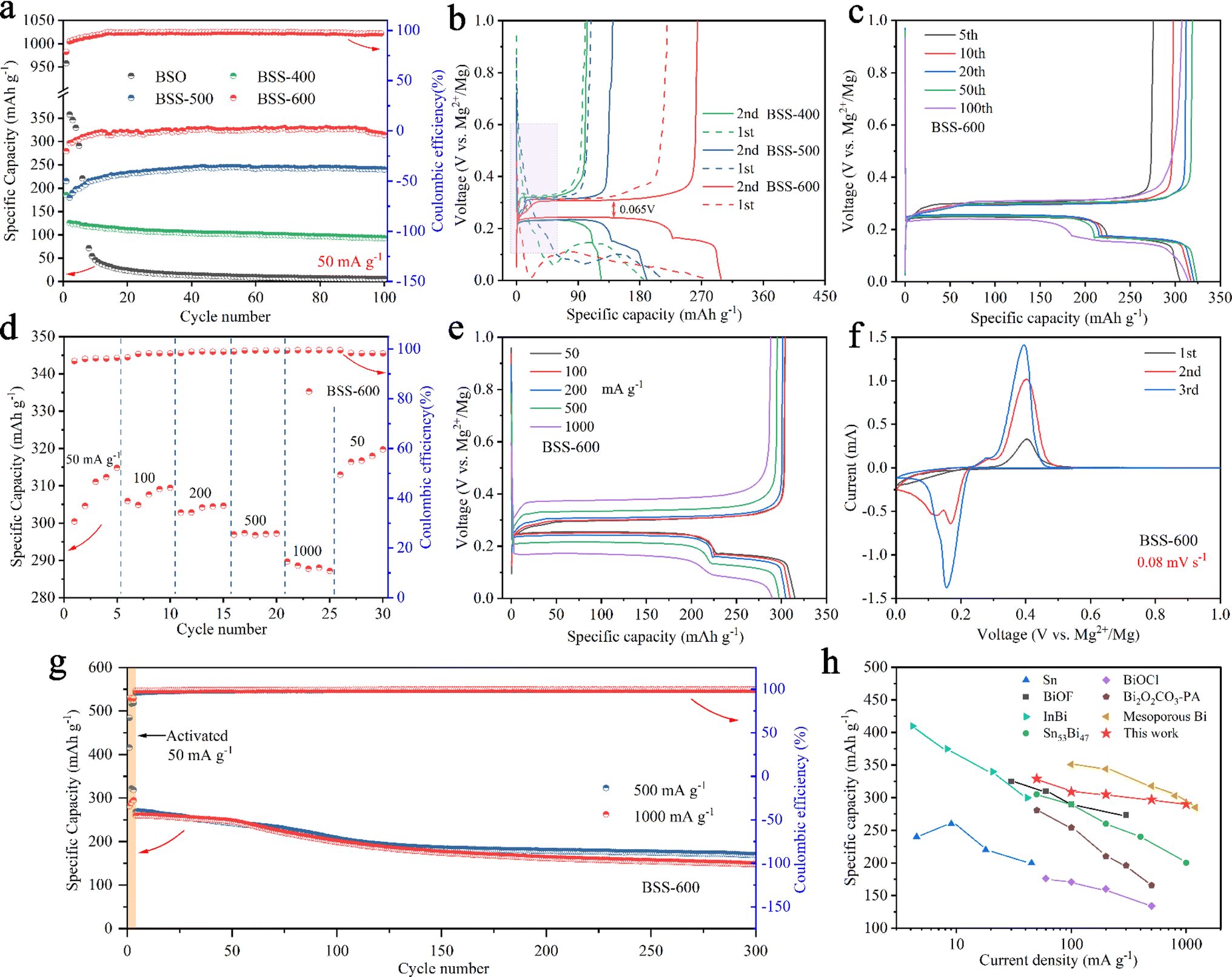 | ||
| Fig. 4 (a) Cycling performance of the as-prepared samples at 50 mA g−1. (b) The first two discharge/charge curves of BSS-400, BSS-500 and BSS-600 corresponding to (a). (c) Discharge/charge profiles of the BSS-600 electrode after different cycles. (d) Rate performance and (e) corresponding discharge/charge curves of the BSS-600 electrode at different current densities. (f) CV curves of the BSS-600 electrode and (g) cycling performance of the BSS-600 electrode at 500 mA g−1 and 1 A g−1. (h) The comparison of rate performance in this work with the reported data in the literature. | ||
The cycle performance of BSS-400 is stable from the second cycle, with a capacity retention rate of 74.4% after 100 cycles. In contrast, BSS-500 and BSS-600 exhibit a significant increase in specific capacities during the first 10 cycles. This observation is in accordance with the structural alterations of electrode particles during the cycling process (Fig. 3), which can be attributed to the process whereby the alloy particles undergo cracking and further nanosizing to form the nanoporous Bi and nano-Sn. After 100 cycles, the capacity of BSS-600 and BSS-500 can reach 314 mA h g−1 and 240 mA h g−1, respectively. As shown in Fig. 4b, the discharge/charge curves of the second cycle of the prepared samples exhibit a distinct plateau during the discharge process. The voltage platform at ∼0.24 V corresponds to the magnesiation of Bi to form Mg3Bi2 (Bi + 1.5Mg2+ + 3e− → 0.5Mg3Bi2) and the voltage platform at ∼0.17 V corresponds to the magnesiation of Sn to form Mg2Sn (Sn + 2Mg2+ + 4e− → Mg2Sn) according to the related literature.39,48,49 The discharge/charge platforms of BSS-600 show a minimum voltage polarization of 0.065 V. Therefore, the following electrochemical tests focus on the BSS-600 alloy.
The discharge/charge profiles of the BSS-600 electrode after different cycles are shown in Fig. 4c. The capacity based on the magnesiation of Sn at ∼0.17 V increases, while the capacity based on the magnesiation of Bi at ∼0.24 V decreases with increasing cycles according to the discharge plateaus. The decrease in magnesiation capacity provided by Bi can be related to the electronic disconnection of Bi fragment resulting from particle pulverization. Additionally, magnesiation capacity corresponding to the contribution of Mg2Sn increases, which can be attributed to the in situ formation of nanosized Sn to improve the electrochemical reactivity. Fig. 4d and e show the rate performance of the BSS-600 electrode at various current densities from 50 to 1000 mA g−1 and the corresponding discharge/charge profiles. The BSS-600 electrode exhibits an initial discharge capacity of 289 mA h g−1 at 50 mA g−1, which gradually increases to 315 mA h g−1 in subsequent cycles. This increase is mainly attributed to the enhanced reactivity and specific surface area of the active material resulting from the cracking of the alloy particles. The BSS-600 electrode exhibits excellent rate capacity, with specific capacities of 297 mA h g−1 at 500 mA h g−1 and 290 mA h g−1 at 1 A g−1. The specific capacity of BSS-600 can reach 320 mA h g−1 when the current density returns to 50 mA g−1, suggesting its excellent current adaptability. The first three CV curves of BSS-600 are shown in Fig. 4f. It shows that two pairs of redox peaks have been formed in the second cycle. The redox potentials at ∼0.16/0.40 V vs. Mg2+/Mg are associated with the magnesiation of Bi and demagnesiation of Mg3Bi2. The redox potentials at ∼0.12/0.29 V vs. Mg2+/Mg are associated with the magnesiation of Sn and demagnesiation of Mg2Sn. The peak intensity increases as the cycling progresses, which demonstrates that the reaction reactivity of Bi and Sn increases during cycling. Furthermore, the cycling performance of the BSS-600 electrodes was evaluated at 500 mA g−1 and 1000 mA g−1. Prior to testing, an activation process consisting of three formation cycles at 50 mA g−1 was conducted. The specific capacity of the activated BSS-600 electrode is 260 mA h g−1 and the specific capacity remains 148 mA h g−1 after 300 cycles at a current density of 1000 mA g−1. At 500 mA g−1, the BSS-600 electrode exhibits a capacity of 170 mA h g−1 after 300 cycles, representing a retention rate of 63.4% in comparison to the initial cycle capacity (268 mA h g−1) following activation. The discharge capacity decreases from 416 mA h g−1 to 322 mA h g−1 during the first two cycles of activation, which can be attributed to the presence of partially unreduced SnOx (0 < x < 3.5) in the test sample, as evidenced by the reaction plateau of 0.6–0.1 V in the first discharge curve (Fig. S8†). Fig. 4h shows a comparison of the rate performance of BSS-600 with the reported data in the literature.32,36,41,47,50–52 Xu et al.32 reported the synthesis of mesoporous Bi through the etching of BiOI nanosheets grown on carbon cloth (BiOI-CC, obtained by a hydrothermal reaction) with Na(BH)4. Inspired by the reduction of Bi-based compounds, the Bi–Sn@SnO2 alloy materials presented in this study were obtained through the thermal reduction of Bi2Sn2O7, a process that combines Bi and Sn alloys and results in the formation of defects in the binary alloy. Nanoporous Bi and nano-Sn were obtained by Bi–Sn phase separation, defects and Mg2+ insertion/extraction, which contributes to the achievement of high rate performance (297 mA h g−1 at 500 mA g−1) and cycle stability (148 mA h g−1 at 1 A g−1 after 300 cycles). The BSS-600 electrode demonstrates excellent transport properties for Mg2+ ions among these reported anode materials.
To evaluate the order of magnitude of the apparent diffusion coefficients of Mg2+ (DMg2+), cyclic voltammetry (CV) at various scan rates was conducted.53,54 As the scan rate increases, the peak current (Ip) grows stronger as shown in Fig. 5a. The peaks corresponding to the redox reactions between Bi and Mg2+ ions were chosen to show the linear relationship between the Ip and the square root of the scanning rate (Fig. 5b). The DMg2+ values related to Bi according to the Randles–Sevcik equation (ESI†), are 2.51 × 10⁻¹⁵ and 1.38 × 10⁻¹⁵ cm2 s−1 (n = ∼1.689, obtained based on the 20th discharge profile in Fig. 4b and corresponding to the plateau reaction Bi + 1.5Mg2+ + 3e− → 0.5Mg3Bi2 at ∼0.24 eV) in the Mg2+ insertion and extraction processes, respectively. Electrochemical impedance spectroscopy (EIS) of the BSS-600 electrode was conducted to further evaluate the DMg2+. EIS of the pristine and activated BSS-600 electrodes is also performed to measure the apparent diffusion coefficient of Mg2+ in the electrode. From Fig. 5c, the internal resistance (Rs) of Mg//BSS-600 cells decreases from 12.96 to 6.54 Ω after activation. These impedance spectra comprise a semicircle in the high-frequency region, corresponding to the charge-transfer resistance (Rct) at the electrode/electrolyte interface, and an inclined line in the low-frequency region. The Rct is regarded as a crucial factor in determining the rate performance of electrodes. Activated BSS-600 has a much lower Rct value (22.15 Ω) compared to pristine BSS-600 (5989 Ω), which might be due to the breakdown of alloy particles and the improved electronic conductivity. At a low frequency, the inclined line was related to the Warburg impedance associated with the diffusion of Mg2+ ions in the electrode materials. DMg2+ values calculated from EIS are 1.17 × 10⁻¹⁵vs. 5.88 × 10⁻¹⁷ cm2 s−1 for activated and pristine BSS-600 electrodes, respectively (Table S2†). A GITT study was carried out to better understand the mechanism of Mg insertion and de-insertion in activated BSS-600 anodes. The approach allows the electrode to reach its equilibrium potential while also providing insights into kinetics phenomena. The thermodynamic potential is stable at ∼0.27 V for the magnesiation of Bi and at ∼0.2 V for the magnesiation of Sn (see the inset of Fig. 5d). It is noted that the OCV potential is reached after fast relaxation, especially the magnesiation of Bi, showing high ion kinetics during the alloying reaction.
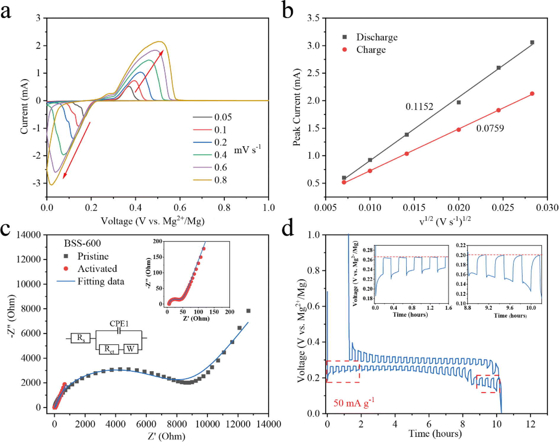 | ||
| Fig. 5 (a) The CV curves of the BSS-600 electrodes at different scan rates from 0.005 to 0.8 mV s−1 and (b) a linear fitting for the relationship between the peak current (Ip) and the scan rate v1/2 from the CV curves. (c) Nyquist plots for pristine BSS-600 and activated BSS-600. The insets show the equivalent circuit for the fitting of impedance and the magnified region of pristine BSS-600. (d) GITT curve obtained from a BSS-600//Mg battery, with 10 min of reduction/oxidation at 50 mA g−1 followed by 10 min of relaxation at the OCV. | ||
2.3 Compositional changes and surface chemistry
The electrochemical reactions of the BSS-600 electrode in different discharge/charge stages of the 4th cycle are investigated by ex situ XRD (Fig. 6a and b). Referring to PDF cards Bi #85-1331 and Sn #86-2265, the diffraction peaks of the Bi and Sn phases in the pristine BSS-600 electrode have shifted to a lower angle by ∼0.1°, which can be attributed to the presence of oxygen vacancies in the pristine BSS-600 electrode according to eqn (1) and (2). When being discharged to the end of the first plateau, the diffraction peaks of hexagonal Mg3Bi2 appear and the peaks corresponding to the Bi phase weaken. It can be concluded that the voltage plateau at 0.24 V is associated with the alloying of Mg with Bi to form Mg3Bi2. After completely discharging to 0.005 V, the diffraction peaks of the cubic Mg2Sn phase are recognized. However, the peaks belonging to the Sn phase strengthen, which could be associated with the exposed Sn phase in the inner part of the BSS-600 particles as the particles crack. Specifically, the peak intensity of the Sn phase at 32.0°, corresponding to its (101) plane, unexpectedly increases and even exceeds its strongest peak at 30.6° corresponding to its (200) plane, which is not observed in other Bi–Sn alloy anodes34,35 and can be attributed to the Sn–SnO2 interface favouring the growth of the (101) plane of Sn. To further verify the discharge/charge process, the XRD patterns of the BSS-600 electrode at various states of the 14th cycle are shown in Fig. 6c and d. When discharged to 0.18 V, the intensity of the Sn phase diffraction peak increases and that of the Bi phase decreases, which suggests that the magnesiation of Bi could cause the separation of Sn from the Bi–Sn alloy to generate fresh Sn. However, only a weak peak at 25.1° belonging to the Mg3Bi2 phase is observed, which is inconsistent with the electrochemical profile and the high capacity contribution at 0.24 V. It can be believed that the amorphous Mg–Bi phase is generated. The defects in Bi–Sn@SnO2 can cause lattice distortion and internal stresses to form amorphous Mg–Bi. In addition, Mg2+ insertion to Bi with large internal strain during the atomic rearrangement process can hinder the formation of crystalline Mg3Bi2. The sharp peak at 25.1° belonging to crystalline Mg3Bi2 is significantly observed after the 20th discharge to 0.18 V (Fig. S9†), indicating a gradual reduction of defects and release of stresses with increasing cycling. The formation of nanoporous Bi and nano-Sn is accompanied by the magnesiation reaction of Bi to form Mg3Bi2. With discharge from 0.18 V to 0.005 V, the peaks corresponding to the Bi phase and Sn phase diminish. It is worth noting that the peak of the Bi phase at 22.5° is close to the peak of the Mg2Sn phase at 22.7°, whereas these two peaks merge at 22.6° and strengthen at full magnesiation (D2). These results indicate the magnesiation of Sn to form mainly MgxSn (0 < x ≤ 2). In subsequent charge in stage C1, the peaks corresponding to the Bi phase and the Sn phase strengthen and the peak intensities return to stage D1, showing the demagnesiation of MgxSn and partial Mg–Bi alloy. With continuous charge to 1 V, the intensity of peaks belonging to the Bi phase increases, suggesting Mg dealloying from the Mg–Bi alloy. The dips in the relative peak signal of Sn may be caused by the considerably higher Bi content in the electrode surface layer, which is induced by phase separation during demagnesiation of the Mg–Bi alloy. Therefore, the peak intensity of Sn is reduced in a certain range of the detection area. The XRD pattern of the BSS-600 electrode in stage C2 (Fig. 6c) exhibits a weaker peak for amorphous Mg–Bi and a stronger peak for Bi in comparison to that of stage C0, indicating an irreversible decrease in amorphous Mg–Bi and fast Mg2+ ion transport in Mg3Bi2 with the formation of nanoporous Bi during cycling, as evidenced by Mg diffusion calculations for amorphous Mg–Bi and crystalline Mg3Bi2.55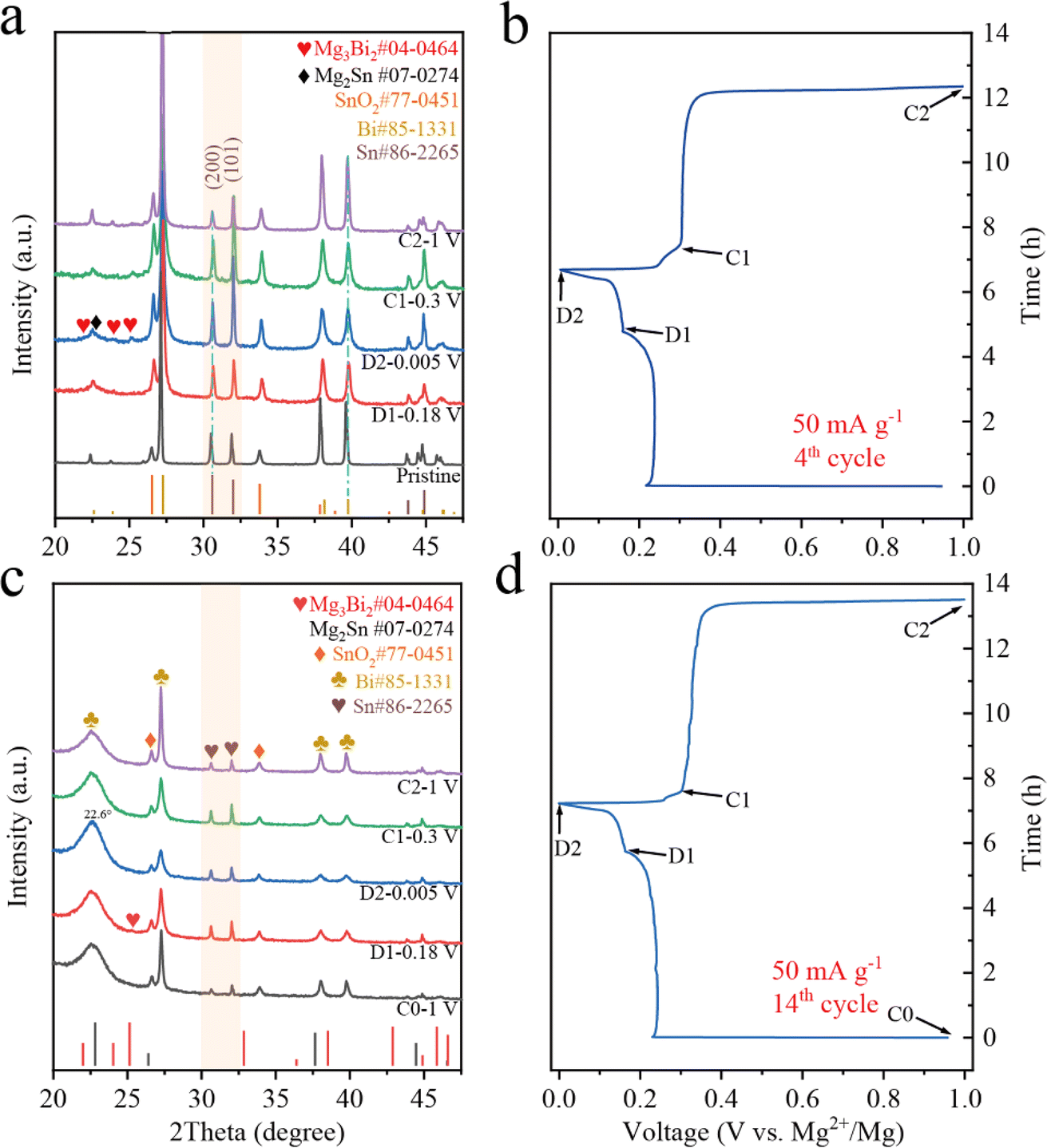 | ||
| Fig. 6 The ex situ XRD patterns and corresponding the discharge/charge curves of the BSS-600 electrodes in the varied states of the 4th cycle (a and b) and the 14th cycle (c and d). | ||
Ex situ XPS was used to investigate the formation and composition of the surface film on the BSS-600 anode resulting from interfacial reactions with the electrolyte during the formation process in the 4th cycle. Fig. 7 summarizes the results of curve fitting conducted on the Bi 4f peaks at 168–155 eV and the broad Sn 3d5/2 peaks at 492–482 eV to determine the relative concentrations of various Bi and Sn species. The surface of the pristine anode contains Sn and Bi metals, which are attributed to the partial amounts of Bi and Sn that were not covered by SnO2 on the BSS-600 anode surface. The binding energies of Bi and Sn are 156.2 and 484.4 eV, lower than their corresponding equilibrium binding energies of 157.0 and 485.0 eV, respectively. The peaks of Bi and Sn have exhibited a shift to the equilibrium binding energy position at various discharge/charge states in the 4th cycle, in comparison to the pristine anode. This phenomenon could be related to the occurrence of defects in the pristine particles, which are produced by a suitable degree of deoxygenation and are associated with small amounts of SnO2. During the discharge/charge process, the defects gradually disappear and a porous alloy is formed as a result of the phase transition and atomic rearrangement associated with Mg2+ insertion/extraction. This observation is in accordance with the ex situ XRD analysis of the BSS-600 electrode above. However, the relatively high surface content of Bi2O3, with the binding energy always at 158.9 eV, is likely due to surface contamination of the BSS-600 anode with air. The presence of SnCl2 and BiCl3 at 487.2 and 159.7 V in Fig. 7 is due to the Cl-transfer in the APC electrolyte to Bi and Sn as suggested in the previous reports.42,56 In particular, the proportions of SnCl2 and BiCl3 gradually dominated with the end of charging, indicating the occurrence of anode–electrolyte interface reactions. In addition, the Sn content of the BSS-600 electrode surface tends to decrease with the charging process, especially in stage C2 where the relative content is extremely low. As the source of SnCl2, Sn is reduced by the formation of SnCl2, which also explains the reduced XRD peak signal when charged to 1 V. The results indicate that the reaction Sn − e− + Cl− → SnCl2 occurs during the charging process. Meanwhile, the presence of inactive SnO2 particles may reduce the reaction at the anode–electrolyte interface. Although SnCl2 is soluble in THF, its formation and dissolution can affect the changes in the anode surface structure and electrochemical performance. The relatively low SnO2 content is noted in stage C2, which appears to be SnO2 being buried by surface SnCl2. The Mg 1s spectrum (Fig. S10†) of pristine appears upon discharge, which is in agreement with the signal of Mg3Bi2 in the Bi 4f spectrum and Mg2Sn in the Sn 3d5/2 spectrum. At full demagnesiation, the Mg signal decreases but does not disappear entirely and the signals from Mg3Bi2 and Mg2Sn are not detected, which may be due to the presence of MgO and MgCO3. Above all, the initial several cycles are thought to be required for the BSS-600 electrode to activate the material from the surface to bulk and produce a stable solid electrolyte interface at the anode surface.
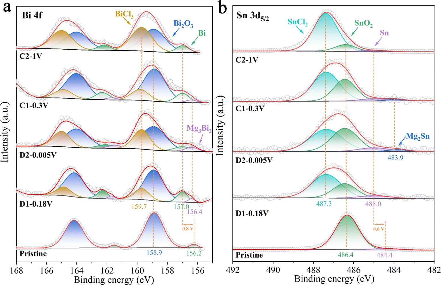 | ||
| Fig. 7 The ex situ XPS spectra at (a) Bi 4f and (b) Sn 3d5/2 regions at different discharge/charge stages in the 4th cycle. | ||
2.4 Compatibility with conventional electrolytes
Full cells were assembled with a pre-magnesiated (Mg) BSS-600 anode and cathode (Mo6S8 and V2O5–PAN) coupling the chloride-free Mg(TFSI)2 electrolytes. For comparison, we also assembled full cells with 0.4 M APC electrolytes, which are known to be corrosive and have a low-voltage window. For the Mo6S8 cathode, the discharge/charge curves of the two full cells at 50 mA g−1 are displayed in Fig. 8a. Despite a decrease in the discharge potential of approximately 0.4 V in the full cells, the cathode-limited cells can still deliver a capacity of 65 mA h g−1 when using the Mg(TFSI)2/G2 electrolytes. The first five discharge/charge profiles of BSS-600(Mg)//Mg(TFSI)2//Mo6S8 in the potential range of 0–1.8 V at a current density of 50 mA g−1 are presented in Fig. S11.† The overpotential of the full cell gradually reduces, which indicates that the BSS-600 electrode has good compatibility with the Mg(TFSI)2/G2 electrolyte. Fig. 8b illustrates the discharge/charge curves of the V2O5–PAN full cells. The BSS-600(Mg)//Mg(TFSI)2//V2O5–PAN full cell has a lower discharge potential than the Mg//APC//V2O5–PAN full cell, which proves that the BSS-600 anode engages in a reversible alloying reaction with Mg2+ ions, not simple Mg adsorption or deposition. According to Fig. 8c, it is shown that the BSS-600(Mg)//Mg(TFSI)2//V2O5–PAN full cell delivers a capacity of 63 mA h g−1 at 50 mA g−1 while the Mg//Mg(TFSI)2//V2O5–PAN full cell shows negligible capacity. In the Mg(TFSI)2/G2 electrolyte, the BSS-600 anode can store Mg2+ ions through phase transition reactions, as schematically illustrated in Fig. 8d, while the Mg metal anode cannot transport Mg2+ ions due to the formation of a passivation layer on the Mg surface. These results suggest that using alloy anodes is a practical solution for the passivation issue between magnesium metal anodes and conventional electrolytes.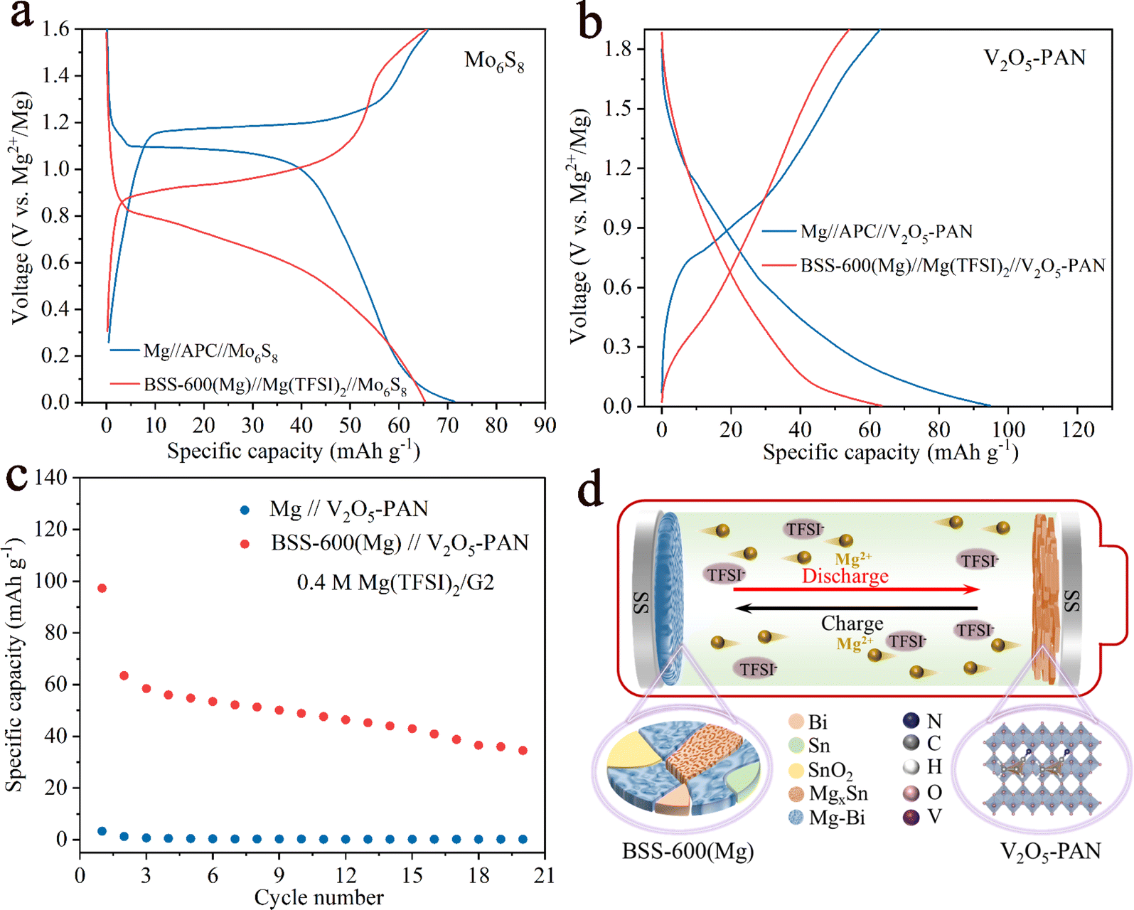 | ||
| Fig. 8 Full-cell discharge/charge curves for the (a) Mo6S8 and (b) V2O5–PAN cathode system at 50 mA g−1. (c) Comparison of cycling performance of the Mg//V2O5–PAN and BSS-600(Mg)//V2O5–PAN full cells using Mg(TFSI)2/G2 electrolyte. (d) Schematic diagram of the full cell with a BSS-600 anode of the rechargeable magnesium batteries. | ||
3 Conclusions
In summary, the design of the Bi–Sn@SnO2 alloy anode involves alloying and structure control. The Bi–Sn@SnO2 alloy was fabricated by annealing the Bi2Sn2O7 precursor at 600 °C for 3 h (BSS-600). The obtained BSS-600 anode can deliver a reversible capacity of 148 mA h g−1 at a current density of 1000 mA g−1 for 300 cycles and exhibit superior rate performance, which could be attributed to the in situ formation of nanoporous Bi and nanosized Sn resulting from Bi–Sn phase separation, defects and Mg2+ insertion/extraction. The nanostructured Bi and Sn could mitigate volume change and deliver high reversible magnesium storage capacity. SnO2 on the Bi–Sn alloy surface can limit the growth of alloy particles and diminish the decomposition of electrolytes. More importantly, the BSS-600 anodes display good compatibility with the Cl-free simple salt Mg(TFSI)2/G2 electrolytes.Data availability
Data can be made available on request.Conflicts of interest
There are no conflicts of interest to declare.Acknowledgements
This work was supported by the National Key R&D Program of China (2023YFB3809500) and the National Natural Science Foundation of China (52171100).References
- D. J. Li, Y. Yuan, J. W. Liu, M. Fichtner and F. S. Pan, J. Magnesium Alloys, 2020, 8, 963–979 CrossRef CAS.
- P. Canepa, G. S. Gautam, D. C. Hannah, R. Malik, M. Liu, K. G. Gallagher, K. A. Persson and G. Ceder, Chem. Rev., 2017, 117, 4287–4341 CrossRef CAS PubMed.
- J. W. Choi and D. Aurbach, Nat. Rev. Mater., 2016, 1, 16013 CrossRef CAS.
- X. B. Cheng and Q. Zhang, J. Mater. Chem. A, 2015, 3, 7207–7209 RSC.
- Z. G. Yang, J. L. Zhang, M. C. W. Kintner-Meyer, X. C. Lu, D. W. Choi, J. P. Lemmon and J. Liu, Chem. Rev., 2011, 111, 3577–3613 CrossRef CAS PubMed.
- J. C. Wang, L. L. Zhao, N. Zhang, P. F. Wang and T. F. Yi, Nano Energy, 2024, 123, 109361 CrossRef CAS.
- H. D. Yoo, I. Shterenberg, Y. Gofer, G. Gershinsky, N. Pour and D. Aurbach, Energy Environ. Sci., 2013, 6, 2265–2279 RSC.
- N. Singh, T. S. Arthur, O. Tutusaus, J. Li, K. Kisslinger, H. L. L. Xin, E. A. Stach, X. D. Fan and R. Mohtadi, ACS Appl. Energ. Mater., 2018, 1, 4651–4661 CrossRef CAS.
- O. Crowther and A. C. West, J. Electrochem. Soc., 2008, 155, A806–A811 CrossRef CAS.
- M. Matsui, J. Power Sources, 2011, 196, 7048–7055 CrossRef CAS.
- C. H. Chen, J. Liu, M. E. Stoll, G. Henriksen, D. R. Vissers and K. Amine, J. Power Sources, 2004, 128, 278–285 CrossRef CAS.
- A. El Kharbachi, O. Zavorotynska, M. Latroche, F. Cuevas, V. Yartys and M. Fichtner, J. Alloys Compd., 2020, 817, 153261 CrossRef CAS.
- S. B. Son, T. Gao, S. P. Harvey, K. X. Steirer, A. Stokes, A. Norman, C. S. Wang, A. Cresce, K. Xu and C. M. Ban, Nat. Chem., 2018, 10, 532–539 CrossRef CAS PubMed.
- Z. Lu, A. Schechter, M. Moshkovich and D. Aurbach, J. Electroanal. Chem., 1999, 466, 203–217 CrossRef CAS.
- R. Attias, M. Salama, B. Hirsch, Y. Goffer and D. Aurbach, Joule, 2019, 3, 27–52 CrossRef CAS.
- I. Shterenberg, M. Salama, Y. Gofer and D. Aurbach, Langmuir, 2017, 33, 9472–9478 CrossRef CAS PubMed.
- T. D. Gregory, R. J. Hoffman and R. C. Winterton, J. Electrochem. Soc., 1990, 137, 775–780 CrossRef CAS.
- D. Aurbach, Z. Lu, A. Schechter, Y. Gofer, H. Gizbar, R. Turgeman, Y. Cohen, M. Moshkovich and E. Levi, Nature, 2000, 407, 724–727 CrossRef CAS PubMed.
- D. Aurbach, G. S. Suresh, E. Levi, A. Mitelman, O. Mizrahi, O. Chusid and M. Brunelli, Adv. Mater., 2007, 19, 4260 CrossRef CAS.
- D. Samuel, C. Steinhauser, J. G. Smith, A. Kaufman, M. D. Radin, J. Naruse, H. Hiramatsu and D. J. Siegel, ACS Appl. Mater. Interfaces, 2017, 9, 43755–43766 CrossRef CAS PubMed.
- H. M. Xu, Z. H. Zhang, J. J. Li, L. X. Qiao, C. L. Lu, K. Tang, S. M. Dong, J. Ma, Y. J. Liu, X. H. Zhou and G. L. Cui, ACS Appl. Mater. Interfaces, 2018, 10, 23757–23765 CrossRef CAS.
- R. Mohtadi, M. Matsui, T. S. Arthur and S. J. Hwang, Angew. Chem., Int. Ed., 2012, 51, 9780–9783 CrossRef CAS PubMed.
- J. Z. Niu, Z. H. Zhang and D. Aurbach, Adv. Energy Mater., 2020, 10, 2000697 CrossRef CAS.
- W. Jin, Z. J. Li, Z. G. Wang and Y. Q. Fu, Mater. Chem. Phys., 2016, 182, 167–172 CrossRef CAS.
- S. C. Jung and Y. K. Han, J. Phys. Chem. C, 2018, 122, 17643–17649 CrossRef CAS.
- Z. G. Liu, J. Lee, G. L. Xiang, H. F. J. Glass, E. N. Keyzer, S. E. Dutton and C. P. Grey, Chem. Commun., 2017, 53, 743–746 RSC.
- T. S. Arthur, N. Singh and M. Matsui, Electrochem. Commun., 2012, 16, 103–106 CrossRef CAS.
- Z. Meng, D. Foix, N. Brun, R. Dedryvère, L. Stievano, M. Morcrette and R. Berthelot, ACS Energy Lett., 2019, 4, 2040–2044 CrossRef CAS.
- J. Z. Niu, H. Gao, W. S. Ma, F. K. Luo, K. B. Yin, Z. Q. Peng and Z. H. Zhang, Energy Storage Mater., 2018, 14, 351–360 CrossRef.
- J. Wang, R. Yu, J. Wang, J. Long, F. Qiao, L. Zhang, G. He, Q. An and L. Mai, J. Magnesium Alloys, 2023, 11, 4181–4188 CrossRef CAS.
- K. V. Kravchyk, L. Piyeteau, R. Caputo, M. He, N. P. Stadie, M. I. Bodnarchuk, R. T. Lechner and M. V. Kovalenko, ACS Nano, 2018, 12, 8297–8307 CrossRef CAS PubMed.
- X. Xu, D. L. Chao, B. Chen, P. Liang, H. Li, F. X. Xie, K. Davey and S. Z. Qiao, Angew. Chem., Int. Ed., 2020, 59, 21728–21735 CrossRef CAS PubMed.
- Y. Y. Shao, M. Gu, X. L. Li, Z. M. Nie, P. J. Zuo, G. S. Li, T. B. Liu, J. Xiao, Y. W. Cheng, C. M. Wang, J. G. Zhang and J. Liu, Nano Lett., 2014, 14, 255–260 CrossRef CAS PubMed.
- J. Z. Niu, K. B. Yin, H. Gao, M. J. Song, W. S. Ma, Z. Q. Peng and Z. H. Zhang, Nanoscale, 2019, 11, 15279–15288 RSC.
- M. J. Song, J. Z. Niu, K. B. Yin, H. Gao, C. Zhang, W. S. Ma, F. K. Luo, Z. Q. Peng and Z. H. Zhang, Nano Res., 2019, 12, 801–808 CrossRef CAS.
- M. J. Song, T. B. Zhang, J. Z. Niu, H. Gao, Y. J. Shi, Y. Zhang, W. S. Ma and Z. H. Zhang, J. Power Sources, 2020, 451, 227735 CrossRef CAS.
- F. Murgia, D. Laurencin, E. T. Weldekidan, L. Stievano, L. Monconduit, M. L. Doublet and R. Berthelot, Electrochim. Acta, 2018, 259, 276–283 CrossRef CAS.
- M. J. Song, J. Z. Niu, H. Gao, T. Y. Kou, Z. K. Wang and Z. H. Zhang, J. Mater. Chem. A, 2020, 8, 13572–13584 RSC.
- D. C. Gu, Y. Yuan, J. W. Liu, D. J. Li, W. B. Zhang, L. Wu, F. Y. Cao, J. F. Wang, G. S. Huang and F. S. Pan, J. Power Sources, 2022, 548, 232076 CrossRef CAS.
- X. Chai, H. Xie, T. T. Zhang, Y. Xin, F. Zhang, B. He, H. Xie, L. Yu and H. Tian, Energy Storage Mater., 2024, 70, 103460 CrossRef.
- N. Singh, T. S. Arthur, C. Ling, M. Matsui and F. Mizuno, Chem. Commun., 2013, 49, 149–151 RSC.
- D. T. Nguyen, X. M. Tran, J. Kang and S. W. Song, Chemelectrochem, 2016, 3, 1813–1819 CrossRef CAS.
- F. Nacimiento, M. Cabello, C. Pérez-Vicente, R. Alcántara, P. Lavela, G. Ortiz and J. Tirado, Nanomaterials, 2018, 8, 501 CrossRef PubMed.
- L. R. Parent, Y. W. Cheng, P. V. Sushko, Y. Y. Shao, J. Liu, C. M. Wang and N. D. Browning, Nano Lett., 2015, 15, 1177–1182 CrossRef CAS PubMed.
- W. Fan, H. Li, F. Zhao, X. Xiao, Y. Huang, H. Ji and Y. Tong, Chem. Commun., 2016, 52, 5316–5319 RSC.
- X. Peng, Y. Yuan, D. Gu, X. Zheng, D. Li, L. Wu, G. Huang, J. Wang and F. Pan, Small, 2024, 2400967 CrossRef PubMed.
- F. Murgia, L. Monconduit, L. Stievano and R. Berthelot, Electrochim. Acta, 2016, 209, 730–736 CrossRef CAS.
- M. Song, T. Zhang, J. Niu, H. Gao, Y. Shi, Y. Zhang, W. Ma and Z. Zhang, J. Power Sources, 2020, 451, 227735 CrossRef CAS.
- F. Zhang, Y. Shen, H. Xu and X. Zhao, ACS Appl. Mater. Interfaces, 2023, 15, 23353–23360 CrossRef CAS PubMed.
- S. Chen, Y. B. Du, H. P. Ma, Z. T. Wang, S. Fan, W. M. Zhang and H. Y. Yang, Nano Lett., 2023, 23, 9788–9795 CrossRef CAS PubMed.
- W. Wang, L. Liu, P. F. Wang, T. T. Zuo, Y. X. Yin, N. Wu, J. M. Zhou, Y. Wei and Y. G. Guo, Chem. Commun., 2018, 54, 1714–1717 RSC.
- C. X. Zhu, Y. K. Tang, L. Liu, X. Bai, Y. Y. Xu, Y. Nuli and J. L. Wang, Mater. Horiz., 2023, 10, 1719–1725 RSC.
- W. Wang, L. Liu, P. F. Wang, T. T. Zuo, Y. X. Yin, N. Wu, J. M. Zhou, Y. Wei and Y. G. Guo, Chem. Commun., 2018, 54, 1714–1717 RSC.
- L. Yang, L. Guo, D. Yan, Y. Wang, T. Shen, D. S. Li, M. E. Pam, Y. Shi and H. Y. Yang, ACS Nano, 2023, 17, 6754–6769 CrossRef CAS PubMed.
- S. C. Jung and Y. K. Han, J. Phys. Chem. C, 2018, 122, 17643–17649 CrossRef CAS.
- D. Aurbach, I. Weissman, Y. Gofer and E. Levi, Chem. Rec., 2003, 3, 61–73 CrossRef CAS PubMed.
Footnote |
| † Electronic supplementary information (ESI) available. See DOI: https://doi.org/10.1039/d4ta04998e |
| This journal is © The Royal Society of Chemistry 2024 |