 Open Access Article
Redox and structural stability for sodium-ion batteries through bond structure engineering†
Xingyu
Li
ab,
Yi
Li
ab,
Qinwen
Cui
ab,
Minghui
Zhong
ab,
Xiaolin
Zhao
*ab and
Jianjun
Liu
 *abc
*abc
aState Key Laboratory of High Performance Ceramics and Superfine Microstructure, Shanghai Institute of Ceramics, Chinese Academy of Sciences, 1295 Dingxi Road, Shanghai 200050, China. E-mail: jliu@mail.sic.ac.cn; zhaoxiaolin@mail.sic.ac.cn
bCenter of Materials Science and Optoelectronics Engineering, University of Chinese Academy of Sciences, Beijing 100049, China
cSchool of Chemistry and Materials Science, Hangzhou Institute for Advanced Study, University of Chinese Academy of Science, 1 Sub-lane Xiangshan, Hangzhou, 310024, China
First published on 1st October 2024
Abstract
With the advancement of sodium-ion batteries, layered manganese-based sodium-ion batteries have garnered significant attention due to their high safety and cost-effectiveness, positioning them as strong contenders for grid-scale energy storage solutions. However, the slow kinetics of sodium ions and the complex phase transitions during charge/discharge cycling hinder the application by decreasing rate capability and cycling performance. In this study, bond structure engineering is employed to regulate the elemental composition of TMO2 slabs by analyzing the bond strength differences within TMO2 slabs. The aim is to enhance the structural stability and suppress the phase transition by increasing the layer spacing of the Na layer and the shrinkage of the TM layer, thereby improving the Na+ ion transport kinetics and mitigating the effects of Na+/vacancy ordering and Jahn–Teller distortion. Consequently, the designed high-entropy O3–NaNi0.2Fe0.2Mn0.3Mg0.1Cu0.1Sn0.1O2 (HE) exhibits improved rate capability and cycling performance. It shows 83.8% capacity retention after 200 cycles at a 3C current density and can stably cycle for 500 cycles at 5C with 75.3% capacity retention. This work provides a new approach for the design of high-entropy manganese-based sodium-layered oxides for energy storage systems.
Introduction
Sodium-ion batteries have garnered significant attention due to the widespread availability of sodium resources and their reliable safety, positioning them as crucial supplementary technology in renewable energy storage and as key complements to lithium-ion batteries.1–3 Layered transition metal oxides are considered promising cathode materials for sodium-ion batteries due to the high energy density and simplified synthesis methods. These materials are typically represented by the formula NaxTMO2, where x denotes the sodium content and TM represents the transition metal ion. At relatively high sodium contents (0.8 < x ≤ 1), layered transition metal oxides generally form O3-phase structures with Na+ ions in octahedral coordination. Conversely, at lower sodium contents (0.4 < x ≤ 0.8), P2-phase structures tend to form with Na+ ions in prismatic coordination.4,5 Higher sodium content usually imparts greater reversible capacity to the material, which explains the significant attention garnered by O3-phase layered transition metal oxides. Owing to the inherently high sodium content, these materials exhibit potential commercial value, especially in the field of energy storage, where they are anticipated to be the key components of high-performance sodium-ion batteries.6,7The economic viability and environmental compatibility of manganese enable O3-phase manganese-based cathode materials to be highly cost-effective and eco-friendly, making them especially attractive for large-scale energy storage systems. Nevertheless, significant challenges remain in successfully applying these materials in practical energy storage devices. One primary challenge is the slow sodium ion kinetics in O3-phase manganese-based materials. In the O3-type structure, sodium ions occupy octahedral sites, and the size of the interlayer spacing directly affects the ease of sodium ion migration.8,9 Narrower interlayer spacing increases the migration barrier, hindering the rapid migration of sodium ions and impacting the battery's rate performance. Additionally, the structural evolution during the sodiation/desodiation process poses a significant challenge. As sodium ions are extracted, the electrostatic repulsion between oxygen atoms within the O3 structure intensifies. This force drives the sliding of the transition metal layer, inducing a phase transition from O3 to P3.10,11 Repeated phase transitions accumulate stresses and eventually lead to the formation of cracks within the material. This seriously affects the mechanical stability and electrochemical properties of the electrode.
In O3-phase manganese-based materials, this situation is exacerbated by unstable redox reactions and the Jahn–Teller effect with Mn3+. This interaction amplifies the sliding tendency and structural distortions of the TM layer, further compromising the material's long-term utilization efficiency and structural stability. Thus, addressing these inherent limitations and engineering TM layers with enhanced structural stability is essential to advancing sodium-ion batteries development. The previous studies reveal that phase modulation and high-entropy strategies effectively address the slow kinetics of sodium ion transport and the complexity of phase transitions in layered manganese-based materials.12–16 The interlocking effect between phase boundaries in O3/P2 phase manganese-based materials designed by phase modulation can generate forces that inhibit the sliding of TMO2 slabs. This is crucial for reducing structural strain, mitigating TMO2 slabs slip and suppressing phase transformation.17–19 In addition, the combination of multiple transition metal elements in high-entropy materials has been demonstrated to effectively modulate charge distribution. The inhibition of Na+/vacancy and charge ordering can suppress interlayer slip and phase transitions, thereby enhancing structural stability.20–22 Thus, the selection of elements and modulation of TMO2 slabs are critical for designing O3-phase high-entropy sodium cathode materials.
In this work, we select the layered manganese-based O3–NaNi0.2Fe0.2Mn0.6O2 (NFM) as the research subject. The alkali metal Mg2+ and the transition metal Cu2+ are screened to regulate the electron distribution of the structure based on the differences in Na–O and TM–O bond lengths among different transition metal elements in the Na–O–TM configuration, aiming to modulate the TMO2 slabs. To compensate for the impact of partial capacity loss on energy density, Sn4+ is used to increase the average voltage of the material, thereby maintaining its energy density. The designed O3–NaNi0.2Fe0.2Mn0.3Mg0.1Cu0.1Sn0.1O2 (HE) with an enlarged Na layer spacing can improve the dynamics of Na+ transport. The contracted TMO2 slabs alleviate the Jahn–Teller effect of Mn3+ and the detrimental impact of Na+/vacancy on structural stability. The prepared high-entropy material exhibits reversible phase transitions and low volume strain (2.6%). HE material has a reversible capacity of 117 mA h g−1, and maintains good rate performance and cycling stability at high rates of 3C and 5C, with capacity of 96 mA h g−1 (83.8% retention after 200 cycles) and 92 mA h g−1 (75.3% retention after 500 cycles), respectively. At a full cell 5C current density, it retains 77.1% of its capacity after 100 cycles.
Results and discussion
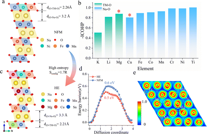
Fig. 1a illustrates the schematic structure of layered O3-type manganese-based NaNi0.2Fe0.2Mn0.6O2 (NFM) (see Fig. S1† for the calculated crystal structure). The primary challenges faced during electrochemical cycling, including structural distortion, Na+/vacancy ordering, and high sodium ion mobility barriers, are directly related to the decrease in poor rate performance and cyclic stability. To address these issues, we employ a strategy by investigating the changes in the Na–O–TM configuration, specifically the TM–O and Na–O bond strengths, by substituting different alkali metals and 3d transition metals at the Mn sites in NFM (Fig. S2†). Fig. 1b presents the −ICOHP values of different elements in the Na–O–TM configuration as a reflection of the bond strengths. Stronger TM–O bonds facilitate the stabilization of the material structure, where Mg–O bonds in alkali metals have the highest bonding strength, enhancing the structural stability of the TMO2 slabs. Weaker Na–O bonds facilitate the extraction/insertion of Na ions, while Cu substitution in the 3d transition metal results in the Na–O–Cu configuration with the lowest Na–O bond strength, which helps to increase the spacing of the Na layers and thus enhances sodium ion transport kinetics. To compensate for the partial capacity loss and maintain energy density, Sn4+ is selected to increase the average voltage.23–26The high-entropy O3–NaNi0.2Fe0.2Mn0.3Mg0.1Cu0.1Sn0.1O2 (HE) material based on the above selected elements exhibits a configurational entropy of 1.7R through eqn (S1).† Compared to NFM, HE demonstrates significant structural optimization: d(O–Na–O) expands from 3.2 Å to 3.3 Å, while d(O–TM–O) contracts from 2.26 Å to 2.21 Å (Fig. 1c). The increased interlayer distance of sodium and the decreased TMO2 slabs spacing contribute to a reduction in the Na+ diffusion barrier from 0.604 eV (NFM) to 0.497 eV (HE), as shown in Fig. 1d (See Fig. S3† for migration pathways). This lowered barrier facilitates the transport kinetics of Na+ and improves the electrochemical performance of the material. To illustrate the impact of multi-element combinations on the structure, the Electron Localization Function (ELF) is used to quantify the charge localization in the oxygen layers (Fig. S4†). As shown in Fig. 1e, the Sn and Cu elements exhibit significant electronic localization, except for Ni, Fe, and Mn. This indicates that more electrons are anchored on the TMO2 slabs, thereby inhibiting phase transitions caused by TMO2 slabs slip during the Na extraction/insertion process.
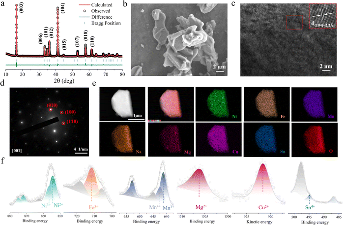
HE and NFM were synthesized using conventional solid-state reaction methods. Fig. 2a and S5† exhibit the X-ray diffraction (XRD) patterns, and the crystal structures are characterized by the space group R![[3 with combining macron]](https://www.rsc.org/images/entities/char_0033_0304.gif) m (detailed refinement results are listed in Tables S1 and S2†). To further investigate the microstructure, scanning electron microscopy (SEM) was employed for morphological analysis. The SEM images in Fig. 2b and S6† illustrate that both HE and NFM exhibit the flake-like morphology. The elemental composition of the electrode materials was confirmed by inductively coupled plasma mass spectrometry (ICP-MS), with results consistent with the chemical formulas provided (detailed information is in Table S3†). High-resolution transmission electron microscopy (HRTEM) was performed to examine the layered distribution and interlayer spacing of the HE electrode material. Fig. 2c and S7† exhibit the layered structural features of HE and NFM, respectively. The d(104) interlayer distance of HE electrode material is 2.20 Å (NFM is 2.17 Å). The selected area electron diffraction (SAED) pattern in Fig. 2d confirm the rhombohedral hexagonal structure of the HE cathode material, indicating excellent crystallinity. Elemental mapping performed using high-resolution energy-dispersive X-ray spectroscopy (EDS) shown in Fig. 2e and S8,† demonstrate the uniform distribution of elements within the electrode material. X-ray photoelectron spectroscopy (XPS) was utilized to determine the oxidation states of the various transition metal elements in HE. The results, depicted in Fig. 2f, show that Ni exists in the oxidation states of +2 and +3, Fe is in the oxidation state of +3, Mn exists in the +3 and +4 oxidation states, Mg, Cu and Sn are the valence states of +2, +2 and +4 respectively.
m (detailed refinement results are listed in Tables S1 and S2†). To further investigate the microstructure, scanning electron microscopy (SEM) was employed for morphological analysis. The SEM images in Fig. 2b and S6† illustrate that both HE and NFM exhibit the flake-like morphology. The elemental composition of the electrode materials was confirmed by inductively coupled plasma mass spectrometry (ICP-MS), with results consistent with the chemical formulas provided (detailed information is in Table S3†). High-resolution transmission electron microscopy (HRTEM) was performed to examine the layered distribution and interlayer spacing of the HE electrode material. Fig. 2c and S7† exhibit the layered structural features of HE and NFM, respectively. The d(104) interlayer distance of HE electrode material is 2.20 Å (NFM is 2.17 Å). The selected area electron diffraction (SAED) pattern in Fig. 2d confirm the rhombohedral hexagonal structure of the HE cathode material, indicating excellent crystallinity. Elemental mapping performed using high-resolution energy-dispersive X-ray spectroscopy (EDS) shown in Fig. 2e and S8,† demonstrate the uniform distribution of elements within the electrode material. X-ray photoelectron spectroscopy (XPS) was utilized to determine the oxidation states of the various transition metal elements in HE. The results, depicted in Fig. 2f, show that Ni exists in the oxidation states of +2 and +3, Fe is in the oxidation state of +3, Mn exists in the +3 and +4 oxidation states, Mg, Cu and Sn are the valence states of +2, +2 and +4 respectively.
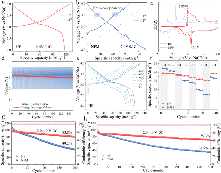
The prepared HE and NFM electrode materials were assembled with sodium metal to form a half-cell for evaluating electrochemical performance (detailed information is provided in Table S4†). Fig. 3a and b demonstrate the initial charge–discharge curves of the HE and NFM electrode materials at a current density of 0.1C within the voltage range of 2–4 V (1C = 120 mA g−1), respectively. HE exhibits a discharge capacity of 117 mA h g−1, whereas NFM reaches a discharge capacity of 136 mA h g−1. This difference was mainly attributed to the higher content of variable-valence element Mn in NFM. However, the charge–discharge curves of NFM reveal multiple voltage plateaus and Na+/vacancy ordering during sodium deintercalation, which pose a challenge to the cyclic stability of the electrode material. In contrast, HE demonstrates smoother charge–discharge curves. The results of dQ/dV comparison indicates that the redox reaction of HE is more reversible, with elevate redox potentials (2.97 V/3.1 V), contributing to the altered voltage profile and increased average voltage (as shown in Fig. 3c). Fig. 3d and S9† illustrate the average discharge voltage decay for HE and NFM, where HE material maintains a higher average discharge voltage and lower voltage decay, further confirming the stability of redox reaction.
The first charge–discharge curves of HE electrode materials at different current densities are depicted in Fig. 3e. HE delivers discharge capacities of 117, 113, 107, 101, 98, and 94 mA h g−1 at 0.1C, 0.3C, 0.5C, 1C, 3C, and 5C rates, respectively. Benefiting from the effect of the adjustment of the layer spacing on the Na+ migration barrier reduction, Na+ diffusion coefficients of HE is consistently higher than those of NFM as shown in the experimental analysis of GITT (Galvanostatic Intermittent Titration Technique) curves, indicating superior sodium ion diffusion kinetics in HE (Fig. S10†). The positive impact of this enhances transport kinetics can be directly observed through rate capability testing (Fig. 3f). The HE electrode's discharge capacities change to 117, 116, 113, 107, 101, 96, and 90 mA h g−1 as the current density transitions from 0.1C, 0.3C, 0.5C, 1C, 3C, 5C, back to 0.1C. In contrast, the discharge capacities for NFM change to 134, 124, 110, 91, 84, 61, 42, and 103 mA h g−1 under the same rate transitions. It is worth noting that when the current density returned to 0.1C, the discharge capacity of the HE material is almost unaffected, indicating a significant improvement in rate performance.
To assess the high-rate performance improvement of high-entropy materials, the cyclic performance of both materials is tested at current densities of 1C, 3C and 5C within the voltage range of 2–4 V. Fig. S11† and 3g illustrate that the capacity retention is 86% after 100 cycles at 1C. After 200 cycles at 3C, the capacity retention of HE is 83.8%, while NFM is only 40.2%. Fig. 3h focuses on the performance testing at a current density of 5C, where HE initially has a capacity of 94 mA h g−1 and still retains a capacity retention rate of 75.3% after 500 cycles, outperforming NFM with a capacity retention rate of 34.9%. In summary, the HE material demonstrates significant performance improvement in both rate performance and high-rate cycling stability, underscoring the significant potential of high-entropy positive electrode materials designed through layered structure modulation to enhance material rate capability and cycling performance.
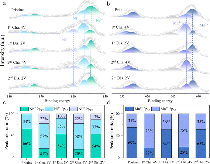
To gain a deeper understanding of the redox mechanism of HE electrode material, XPS tests are conducted on the HE electrode material at different charge–discharge states. Fig. 4a and c exhibit the variations of the Ni 2p core spectra during the charge–discharge process and the relative content changes of Ni in different valence states. In the initial state, the peaks at 854.5 eV and 856.6 eV in the Ni core spectra correspond to Ni2+ and Ni3+, respectively.27,28 Upon initial charging to 4 V, a new peak appears at 859.8 eV in the core spectra, indicating the coexistence of Ni2+, Ni3+, and Ni4+ valence states, with Ni3+ comprising approximately 57%. As the voltage is discharged to 2 V, the intensities of the Ni3+ and Ni4+ peaks decreases while the proportion of Ni2+ increases, indicating a reduction reaction of Ni4+/3+/2+. In the subsequent charge–discharge process, Ni undergoes a reversible redox reaction between Ni2+/3+/4+. Fig. 4b and d depict the changes in the Mn 2p core spectra and the proportions of different valence states at different charge–discharge states. Initially, the peaks at 641.1 eV and 642.3 eV in the Mn core spectra represent Mn3+ and Mn4+, with Mn3+ accounting for approximately 69%.29,30 Upon initial charging to 4 V, Mn3+ is oxidized to Mn4+, increasing the proportion of Mn4+ to 78%. During the subsequent discharge process, Mn4+ is reversibly reduced back to Mn3+, with the proportion of Mn4+ decreasing to 36%. Throughout the following charge–discharge cycles, Mn exhibits a stable Mn3+/4+ redox reaction. Thus, during the cycling process, the stable and reversible redox reactions of Ni2+/3+/4+ and Mn3+/4+ contribute to the reversible capacity of HE. Fig. S12† illustrates the evolution of the Ni and Mn 2p core spectra in the NFM during the charging process. The primary contributors to the reversible capacity are the oxidation processes of Mn3+/4+ and Ni2+/3+/4+. The proportion of capacity contributed by the redox reactions of Ni2+/3+/4+ is 35% and 49% in NFM and HE materials. In addition, the increase in the proportion of high valence Ni4+ in HE (from 15% to 22%) brings about an increase in the average valence of the Ni element, which contributes to the increase in the average voltage in HE.
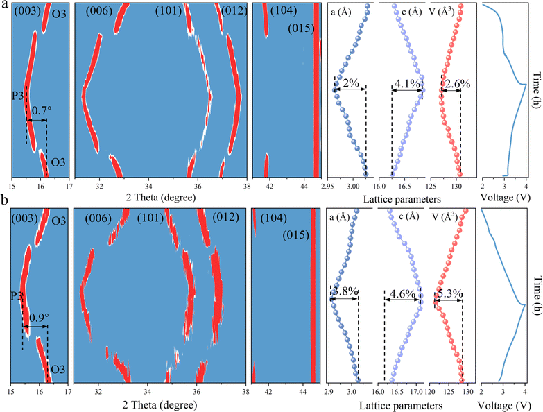
To elucidate the effects of TMO2 slabs modified by bond structure engineering on the structural stability, in situ XRD is employed to visualize the phase transitions occurring during the charging and discharging cycles. As illustrated in Fig. 5a, the primary peak (003) of the HE material progressively shifts towards lower angles during the charging phase, which coincides with the transformation from the O3 phase to the P3 phase. Upon completion of charging, the (003) peak had shifted by 0.7° compared to its initial position. During the subsequent discharging phase, the (003) peak gradually migrates back towards higher angles, eventually returning to its original location. Throughout this entire process, the lattice constants a, c and V undergo subtle variations of 2%, 4.1%, and 2.6%, respectively. In comparison, the NFM material also experiences a reversible O3–P3–O3 phase transition (Fig. 5b). However, the (003) peak demonstrates a larger angular displacement of 0.9° during the charging and discharging cycles, indicating a more pronounced phase transformation. Concurrently, the lattice constants a and c, along with the cell volume V change by 3.8%, 4.6%, and 5.3%, respectively. The greater degree of structural change in the NFM material highlights the improved structural stability and suppression of phase transition in the HE materials. This finding underscores the effectiveness of bond structure engineering in optimizing the structural integrity and phase behavior of TMO2 slabs, which is crucial for improving the electrochemical performance and longevity of sodium-ion battery cathode materials.
In order to exhibit the improved structural stability of the HE material under repeated sodium removal/embedding processes, the electrode material with 100 cycles is employed for XRD testing as a means of comparing the structural changes. Fig. S13† illustrates that after 100 cycles, HE still maintains the O3 phase structure, while the NFM is in a mixed phase of O3 and P3. This indicates that the structure of the NFM cannot remain stable as HE after multiple cycles, and part of the P3 phase during the phase transition fails to be reversibly changed to the O3 phase. For this phenomenon, EIS and GITT test are employed to detect the impedance change to analyse its effect on the performance of the battery (Fig. S14†). The resistance of HE decreases from 545 Ω to 172 Ω, while NFM only decreases from 707 Ω to 316 Ω. The diffusion coefficients of sodium ions of HE remains stable and higher than those of NFM after ten cycles. Furthermore, SEM images of the materials after cycling reveal that the HE materials retains the bulk morphology, demonstrating improved structural stability (Fig. S15†). In contrast, the NFM shows significant cracking. These observations confirm the enhanced structural stability of the HE material, which can withstand the stresses generated by repeated insertion and extraction of sodium ions without causing significant structural damage. This structural stability justifies the effectiveness of bond structure engineering in optimizing the structure of the TMO2 slabs, thereby improving the integrity and overall electrochemical performance of the particles.
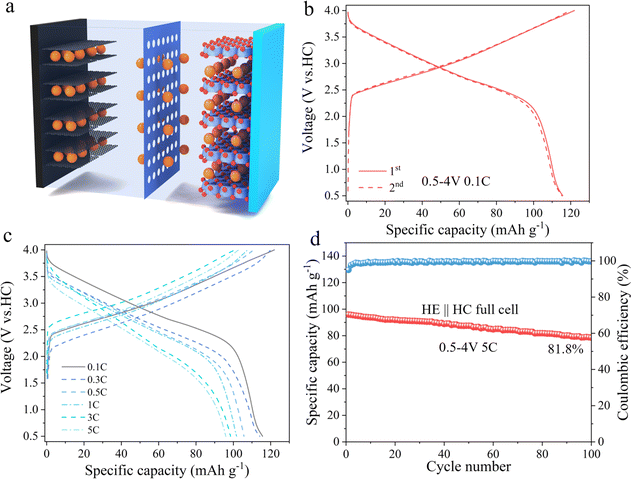
To evaluate the practical application potential of HE electrode material, it was paired with hard carbon (HC) and assembled into a full cell, as schematically illustrated in Fig. 6a. Fig. 6b displays the charge–discharge curves of the full cell within a voltage window of 0.5–4 V at a current density of 0.1C. Under these conditions, the HE electrode material exhibits an initial discharge capacity of 115 mA h g−1. Fig. 6c further reveals the first cycle charge–discharge curves of the material at different current densities, with initial discharge capacities of 115, 114, 105, 101, 97, and 95 mA h g−1 at 0.1C, 0.3C, 0.5C, 1C, 3C, and 5C current densities, respectively. Fig. 6d presents the cycling performance of HE at 5C, indicating that it retains a discharge capacity of 78.6 mA h g−1 after 100 cycles, with a capacity retention rate of 81.8%. These results prove that the HE electrode material possess good electrochemical performance in practical applications.
Conclusions
In this study, the TMO2 slabs are rationally modified by analyzing the differences in bond strengths of different elements in the Na–O–TM configuration, leading to structural contraction, while the enlarged Na layer spacing reduces the Na+ diffusion barrier. This structural change positively impacts the electrochemical performance, effectively enhancing the rate performance of the material. In addition, the charge rearrangement brought about by the introduction of multiple elements allows more electrons to be immobilized in the TMO2 slabs, thus suppressing the slippage of the TMO2 slabs during the desodiation/sodiation process. The synthesized high-entropy electrode material HE exhibits better structural stability and significant performance enhancement in half battery (75.3%/500th) and full battery (81.8%/100th) at 5C. This study emphasizes the potential of bond strength modulation in improving the phase transition and structural stability degradation in manganese-based electrode materials, and provides new design ideas for designing high-entropy manganese-based sodium electrode cathode materials.Data availability
The data that support the findings of this study are available from the corresponding author upon reasonable request.Author contributions
J. Liu conceived and designed this work. X. Li performed all DFT calculations and experiments. Y. Li, Q. Cui, M. Zhong and X. Zhao provided some help in DFT calculations and experiments. X. Li, X. Zhao and J. Liu wrote and revised this manuscript.Conflicts of interest
There are no conflicts to declare.Acknowledgements
The authors are grateful for the financial support from National Key R&D Program of China (2022YFB3807200), National Natural Science Foundation of China, NSFC (22133005, 22103093), Science and Technology Commission of Shanghai Municipality (21ZR1472900, 22ZR1471600, 23ZR1472600), the Youth Innovation Promotion Association CAS (2022251), the Shanghai Super Post-Doctor Incentive Program (2022665), China Postdoctoral Science Foundation (2023M733621) and the Shanghai Explorer Program (Batch I) (23TS1401500).References
- Y. Zhao, Y. Kang, J. Wozny, J. Lu, H. Du, C. Li, T. Li, F. Kang, N. Tavajohi and B. Li, Nat. Rev. Mater., 2023, 8, 623–634 CrossRef CAS.
- J.-Y. Hwang, S.-T. Myung and Y.-K. Sun, Chem. Soc. Rev., 2017, 46, 3529–3614 RSC.
- C. Vaalma, D. Buchholz, M. Weil and S. Passerini, Nat. Rev. Mater., 2018, 3, 18013 CrossRef.
- C. Delmas, C. Fouassier and P. Hagenmuller, Physica B+C, 1980, 99, 81–85 CrossRef CAS.
- C. Zhao, Q. Wang, Z. Yao, J. Wang, B. Sánchez-Lengeling, F. Ding, X. Qi, Y. Lu, X. Bai, B. Li, H. Li, A. Aspuru-Guzik, X. Huang, C. Delmas, M. Wagemaker, L. Chen and Y.-S. Hu, Science, 2020, 370, 708–711 CrossRef CAS PubMed.
- C. Delmas, Adv. Energy Mater., 2018, 8, 1703137 CrossRef.
- Y. Fang, L. Xiao, Z. Chen, X. Ai, Y. Cao and H. Yang, Electrochem. Energy Rev., 2018, 1, 294–323 CrossRef CAS.
- K. Kubota, N. Yabuuchi, H. Yoshida, M. Dahbi and S. Komaba, MRS Bull., 2014, 39, 416–422 CrossRef CAS.
- Y. Liu, D. Wang, H. Li, P. Li, Y. Sun, Y. Liu, Y. Liu, B. Zhong, Z. Wu and X. Guo, J. Mater. Chem. A, 2022, 10, 3869–3888 RSC.
- T. Cui, L. Liu, Y. Xiang, C. Sheng, X. Li and Y. Fu, J. Am. Chem. Soc., 2024, 146, 13924–13933 CrossRef CAS PubMed.
- S. Gao, Z. Zhu, H. Fang, K. Feng, J. Zhong, M. Hou, Y. Guo, F. Li, W. Zhang, Z. Ma and F. Li, Adv. Mater., 2024, 36, 2311523 CrossRef CAS PubMed.
- X.-L. Li, J. Bao, Y.-F. Li, D. Chen, C. Ma, Q.-Q. Qiu, X.-Y. Yue, Q.-C. Wang and Y.-N. Zhou, Adv. Sci., 2021, 8, 2004448 CrossRef CAS PubMed.
- T. Cui, X. Li, Y. Si and Y. Fu, Energy Storage Mater., 2024, 65, 103161 CrossRef.
- F. Fu, X. Liu, X. Fu, H. Chen, L. Huang, J. Fan, J. Le, Q. Wang, W. Yang, Y. Ren, K. Amine, S.-G. Sun and G.-L. Xu, Nat. Commun., 2022, 13, 2826 CrossRef CAS PubMed.
- W. Li, D. Peng, W. Huang, X. Zhang, Z. Hou, W. Zhang, B. Lin and Z. Xing, Carbon, 2023, 204, 315–324 CrossRef CAS.
- L. Cheng, C. Ma, W. Lu, X. Wang, H. Yue, D. Zhang and Z. Xing, Chem. Eng. J., 2022, 433, 133527 CrossRef CAS.
- L. Yu, Z. Cheng, K. Xu, Y.-X. Chang, Y.-H. Feng, D. Si, M. Liu, P.-F. Wang and S. Xu, Energy Storage Mater., 2022, 50, 730–739 CrossRef.
- M. Li, H. Zhuo, M. Song, Y. Gu, X. Yang, C. Li, Z. Liao, Y. Ye, C. Zhao, Y. Jiang, J. Liang, D. Wang, K. Wang, D. Geng and B. Xiao, Nano Energy, 2024, 123, 109375 CrossRef CAS.
- P. Zhou, Z. Che, J. Liu, J. Zhou, X. Wu, J. Weng, J. Zhao, H. Cao, J. Zhou and F. Cheng, Energy Storage Mater., 2023, 57, 618–627 CrossRef.
- R. Li, X. Qin, X. Li, J. Zhu, L.-R. Zheng, Z. Li and W. Zhou, Adv. Energy Mater., 2024, 14, 2400127 CrossRef CAS.
- F. Ding, C. Zhao, D. Xiao, X. Rong, H. Wang, Y. Li, Y. Yang, Y. Lu and Y.-S. Hu, J. Am. Chem. Soc., 2022, 144, 8286–8295 CrossRef CAS PubMed.
- B. Wang, J. Ma, K. Wang, D. Wang, G. Xu, X. Wang, Z. Hu, C.-W. Pao, J.-L. Chen, L. Du, X. Du and G. Cui, Adv. Energy Mater., 2024, 14, 2401090 CrossRef CAS.
- Y.-F. Zhu, Y. Xiao, S.-X. Dou and S.-L. Chou, Cell Rep. Phys. Sci., 2021, 2, 100631 CrossRef CAS.
- P.-F. Wang, H. Xin, T.-T. Zuo, Q. Li, X. Yang, Y.-X. Yin, X. Gao, X. Yu and Y.-G. Guo, Angew. Chem., Int. Ed., 2018, 57, 8178–8183 CrossRef CAS PubMed.
- C. Zhao, F. Ding, Y. Lu, L. Chen and Y.-S. Hu, Angew. Chem., Int. Ed., 2020, 59, 264–269 CrossRef CAS PubMed.
- H. Gao, J. Li, F. Zhang, C. Li, J. Xiao, X. Nie, G. Zhang, Y. Xiao, D. Zhang, X. Guo, Y. Wang, Y.-M. Kang, G. Wang and H. Liu, Adv. Energy Mater., 2024, 14, 2304529 CrossRef CAS.
- X.-Y. Du, Y. Meng, H. Yuan and D. Xiao, Energy Storage Mater., 2023, 56, 132–140 CrossRef.
- G. Zhang, Y. Gao, P. Zhang, Y. Gao, J. Hou, X. Shi, J. Ma, R. Zhang and Y. Huang, Mater. Horiz., 2024, 11, 3935–3945 RSC.
- X. Zhang, F. Xie, X. Wang, T. Liu, L. Zhang and J. Yu, J. Mater. Chem. A, 2024, 12, 19440–19451 RSC.
- X. Zhang, W. Zuo, S. Liu, C. Zhao, Q. Li, Y. Gao, X. Liu, D. Xiao, I. Hwang, Y. Ren, C.-J. Sun, Z. Chen, B. Wang, Y. Feng, W. Yang, G.-L. Xu, K. Amine and H. Yu, Adv. Mater., 2024, 2310659 CrossRef CAS PubMed.
Footnote |
| † Electronic supplementary information (ESI) available. See DOI: https://doi.org/10.1039/d4ta05924g |
| This journal is © The Royal Society of Chemistry 2024 |

