Novel valleytronic and piezoelectric properties coexisting in Janus MoAZ3H (A = Si, or Ge; Z = N, P, or As) monolayers†
Xiaolin
Cai
 *a,
Guoxing
Chen
a,
Rui
Li
a,
Zhixiang
Pan
a and
Yu
Jia
 *bc
*bc
aSchool of Physics and Electronic Information Engineering, Henan Polytechnic University, Jiaozuo 454000, China. E-mail: caixiaolin@hpu.edu.cn
bKey Laboratory for Special Functional Materials of Ministry of Education, Collaborative Innovation Center of Nano Functional Materials and Applications, School of Material Science and Engineering, Henan University, Kaifeng 475004, China. E-mail: jiayu@henu.edu.cn
cInternational Laboratory for Quantum Functional Materials of Henan, and School of Physics and Microelectronics, Zhengzhou University, Zhengzhou 450001, China
First published on 1st March 2024
Abstract
In this paper, for the newly proposed two-dimensional (2D) Janus MoAZ3H (A = Si, or Ge; Z = N, P, or As) monolayer (ML) materials, we theoretically explore the valleytronic and piezoelectric properties using first-principles calculations. The calculated results show that Janus MoAZ3H MLs have obvious valleytronic properties due to the broken inversion symmetry and strong spin–orbit coupling (SOC) effects, and the spin-valley coupling of MoAZ3H MLs can be enhanced from 173 to 283 meV by changing the A or Z element, comparable to the corresponding MoA2Z4 MLs. The non-zero Berry curvatures with opposite signs at the K and K′ points can induce the valley Hall effect. Furthermore, Janus MoAZ3H MLs exhibit obvious in-plane and out-of-plane piezoelectric responses, and their independent d11 and d31 piezoelectric coefficients range from 1.62 to 8.60 pm V−1 and from 0.058 to 0.325 pm V−1, respectively. This piezoelectricity is much stronger than those of the corresponding MoA2Z4 and MoSiGeN4 MLs, attributed to the unique Janus structure of the MoAZ3H MLs. More importantly, strain can tailor both the spin-valley coupling and piezoelectricity of the MoAZ3H MLs. Our findings not only enrich the excellent properties of the MoAZ3H MLs, but also indicate a direction for their application in valleytronics and energy conversion devices.
1. Introduction
The extreme values of electronic energy in momentum space are referred to as energy valleys in crystals,1 which gives electrons an additional degree of freedom except for charge and spin, the valley degree of freedom.2,3 Valleytronic devices based on the valley degree of freedom as information carriers have unique advantages, such as high integration, fast processing speed, low energy consumption, and nonvolatile nature, and have been considered as the development direction of future electronic devices.4–8 The booming two-dimensional (2D) materials provide an ideal platform for the study of valleytronics. The newly discovered MA2Z4 (M = Mo, W, V, Nb, Ta, Ti, Zr, Hf or Cr; A = Si or Ge; Z = N, P or As) monolayer (ML) family,9 with a septuple-layer structure, is another intriguing family of 2D valleytronic materials10,11 after the transition metal dichalcogenides (TMDCs) represented by MoS2,12,13 which is attributed to their broken inversion symmetry and strong spin-orbital coupling (SOC) effect. Among them, one class of members has a twofold valley degeneracy related by time-reversal symmetry at the K and K′ points of the hexagonal Brillouin zone, which exhibits extraordinary spin valley-coupling in the two nonequivalent valleys, leading to valley transport characteristics and spin-valley coupling optical selection rules,14–16 including MoSi2Z4 (Z = N, P, or As), MSi2N4 (M = Hf, Ti, or Zr), WA2Z4 (A = Si, or Ge; Z = P, or As), etc. In addition, when the magnetic moments are out-of-plane, the spontaneous valley polarization can be driven by both the inversion and time-reversal symmetries breaking in magnetic VSi2N4 and VSi2P4 MLs.17,182D Janus materials have garnered increasing attention owing to their unique physical properties arising from the dissimilar types of atoms on each side.19 The larger thickness makes the MA2Z4 MLs have an advantage over the other ML materials in constructing Janus structures. Substituting the Ge element for the Si element in the MSi2N4 (M = V, Mo, W, Zr, or Hf) ML can form stable Janus MSiGeN4 MLs, which induces tunable electronic properties,20 efficient photocatalytic properties,21,22 Rashba splitting,23,24 and valley and spin properties.25–27 The Janus ML XYSiN2 (X = S, Se, or Te; Y = Mo, or Cr) materials have good stability, high mechanical strength and excellent electronic properties,28,29 and can be constructed by substituting chalcogen X atoms for the SiN2 layer on either side of the central Mo atoms in the MoSi2N4 MLs. Forming Janus structures breaks the vertical symmetry of the ML materials and thus causes out-of-plane piezoelectric properties, which is exactly required for energy conversion devices. For instance, Guo et al. found both in-plane and out-of-plane piezoelectric polarizations in MSiGeN4 (M = Mo, or W) MLs.24
Our group theoretically proposed the Janus MoAZ3H (A = Si, or Ge; Z = N, P, or As) ML materials by substituting H atoms for one AZ atomic layer of MoA2Z4 MLs, exhibiting semiconducting nature with high carrier mobility, and excellent photovoltaic and catalytic performances.30 However, for such a system including both a strong SOC effect and broken inversion symmetry, the valleytronic and piezoelectric characteristics are not uncovered, which is crucial for their application in valleytronics and energy conversion devices. Consequently, this work aims to systematically explore the valleytronic and piezoelectric properties of MoAZ3H MLs using first-principles calculations. The calculated results show that the Janus MoAZ3H MLs have obvious valleytronic properties, and comparable spin-valley coupling to that of the corresponding MoA2Z4 MLs, in which the valley Hall effects are observed attributed to the non-zero Berry curvatures with opposite signs at the K and K′ points. Also, Janus MoAZ3H MLs not only exhibit stronger in-plane piezoelectric response than the corresponding MoA2Z4 MLs, but also have obvious out-of-plane piezoelectric responses induced by the unique Janus structures. Furthermore, strain can tailor both the spin-valley coupling and piezoelectricity of MoAZ3H MLs. Our results show that the MoAZ3H MLs with the valleytronic and piezoelectric properties coexisting are promising for valleytronic and energy conversion devices in future.
2. Computational details
All calculations are performed in the Vienna ab initio simulation package (VASP)31 based on density functional theory (DFT).32 The exchange correlation potential is described by the generalized gradient approximation (GGA)33 with the Perdew–Burke–Ernzerhof (PBE) functional. The cut off energy of the plane wave is set to 500 eV, and the convergence criteria are 10−5 eV and 0.01 eV Å−1 for the energy and the force, respectively. The vacuum space is set to 30 Å to avoid adjacent interactions. The 21 × 21 × 1 Monkhorst–Pack k-point mesh is used to sample the Brillouin zone. The Heyd–Scuseria–Ernzerhof (HSE)34 hybrid functional method is used to obtain a more precise band structure. The maximum-localized Wannier function (MLWF) calculated by the WANNIER9035 package is used to obtain the high-symmetry point Berry curvature, and the Berry curvature of the 2D section is plotted by the VASPBERRY code.36 Meanwhile, the spin texture is calculated using VAVSPKIT.373. Results and discussion
Fig. 1 presents the crystal structures of Janus MoAZ3H MLs and corresponding high-symmetric path in the Brillouin zone. It is clearly found that the Janus MoAZ3H MLs can be obtained by replacing one AZ layer with H atoms in the MoA2Z4 ML, which still maintains the hexagonal lattice structure, with six atomic layers in a queue of H–Z–Mo–Z–A–Z. As the atomic number of the A or Z element increases, both the lattice constants and the thicknesses of the MoAZ3H MLs also gradually increase.3.1 Valleytronic properties
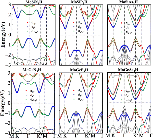
In order to unveil the valleytronic properties of the MoAZ3H MLs, we firstly plot the projected band structure of atomic contributions using the PBE scheme, as shown in Fig. S1 (ESI†). Distinctly, the conduction band minima (CBMs) of all the six MoAZ3H MLs are at the K point. Meanwhile, the K point is either the valence band maximum (VBM) or the extreme point of the energy for the highest valence band. All the electronic states of the CBMs and the highest valence bands at the K points are mainly determined by the Mo atom of the MoAZ3H MLs. Further calculated results in Fig. 2 show that the Mo orbital-resolved band structure shows that the CBM is mainly from the Mo-dz2 orbital, while the highest valence band at the K point is contributed by the Mo-dx2−y2 and -dxy orbitals. As a result of the C3h group at K/K′, the basis functions are chosen as |φτc〉 = |dz2〉 and , where the subscript c(v) indicates conduction (valence) band, and τ = ±1 is the valley index corresponding to the K/K′ point. When we approximate the SOC term as an intra-atomic contribution and only keep the leading-order term, the k·p effective model is obtained as
 | (1) |
 refers to the Pauli matrices for the two basis functions, and α and Δ are real-valued model parameters. The third term on the right side of the above equation is the SOC effect term, where ŝz is the Pauli matrix for spin and λ is the effective SOC strength. The energies of the VBM and CBM at the K/K′ point are Eτv = 〈φτv|Ĥτ|φτv〉 and Eτc = 〈φτc|Ĥτ|φτc〉. Based on the above analysis, we can obtain the spin splitting of the VBM and CBM at the K/K′ point:
| ΔEv = E−v − E+v = i〈dxy|Ĥτ|dx2−y2〉 − i〈dx2−y2|Ĥτ|dxy〉 = 2λ, | (2) |
| ΔEc = E−c − E+c = 0. | (3) |
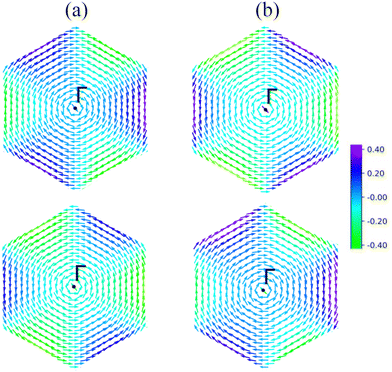
Fig. 3 shows the spin-resolved band structures of MoAZ3H MLs along the path of M–K–Γ–K′–M–Γ using the PBE+SOC method. Firstly, as discussed above, there exists obvious spin splitting in the band structures of MoAZ3H MLs resulting from the strong SOC effect. In particular, due to the broken inversion symmetry as well as the preserved time-reversal symmetry, the highest valence bands at the K′ and K points have spin polarization in the opposite direction, proving that the Janus MoAZ3H MLs have valleytronic properties. These valleytronic properties can also be illustrated by the spin texture for the two highest spin-splitted valence bands at the K/K′ point over the entire Brillouin zone, and for simplicity, we only calculate the spin texture for MoSiP3H and MoGeAs3H MLs, as shown in Fig. 4. It is clearly revealed that the out-of-plane components of the spin polarization at the K and K′ points are opposite at the same band (Fig. 4(a) and (b)); meanwhile, the in-plane components of the spin polarization at the K or K′ points are also opposite at different bands (Fig. 4(a) and (b)). This fully illustrates the opposite spin polarizations of the highest valence band at the K and K′ points caused by the strong SOC under the spatial inversion symmetry breaking in Janus MoAZ3H MLs.
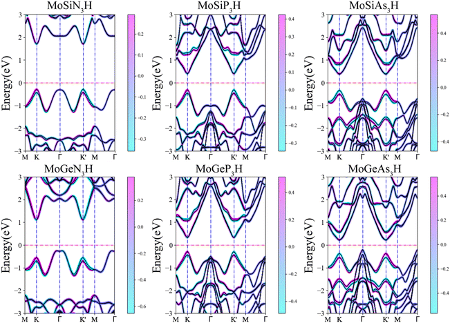 | ||
| Fig. 3 Spin-resolved band structures of Janus MoAZ3H MLs by the PBE+SOC method. Here, the Fermi levels are set to zero. | ||
Table 1 lists the spin-valley coupling (ΔV) and band gap (Eg) of MoAZ3H MLs both from the PBE+SOC and HSE+SOC schemes. Compared to the PBE+SOC method, although the HSE+SOC method significantly enhances the band gap and spin-valley coupling of the MoAZ3H ML (Fig. S2, ESI†), they both predict the same variation trends of the band gap and the spin-valley coupling when substituting Ge for Si or substituting P or As for N in the MoAZ3H MLs. Among the six members, the MoSiN3H ML has the smallest spin-valley coupling, about 173 meV, which will increase with both substituting Ge for Si and substituting P or As for N due to the larger radius and mass of the replaced atom. As a result, the largest spin-valley coupling is for MoGeAs3H ML, up to 283 meV. It is worth noting that the replacement of the element in Group V has a greater impact on the spin-valley coupling than that in Group IV because there are more atoms with larger mass in Group V in MoAZ3H MLs. Previous studies reported that the spin-valley coupling values were 170, 206 and 295 meV for MoSi2N4, MoSi2P4 and MoSi2As4 MLs,38 respectively. This means that replacing one SiN or SiP layer with H atoms in the MoSi2N4 ML basically does not change the spin-valley coupling, whereas replacing the SiAs layer with H atoms can slightly reduce the spin-valley coupling due to the lighter replaced atoms.
| E PBE+SOCg | E HSE+SOCg | E PBE+SOCv | E HSE+SOCv | |
|---|---|---|---|---|
| MoSiN3H | 2.00 | 2.44 | 136 | 173 |
| MoSiP3H | 0.73 | 0.95 | 143 | 203 |
| MoSiAs3H | 0.69 | 0.83 | 172 | 267 |
| MoGeN3H | 1.37 | 1.93 | 143 | 184 |
| MoGeP3H | 0.63 | 0.78 | 145 | 211 |
| MoGeAs3H | 0.43 | 0.69 | 180 | 283 |
Unlike the magnetic MLs with the broken time reversal symmetry, such VSi2P439 and Mn2P2X3Y340 MLs have spontaneous valley polarization. The valley characteristics of Janus MoAZ3H MLs arise from the spatial inversion symmetry breaking and strong SOC effects, which manifest as spin-valley coupling or opposite spin splitting at the K/K′ point, protected by time reversal symmetry. As the atomic number of element A or Z increases, the spin-valley coupling of the MoAZ3H MLs ranges from 173 to 283 meV, which is larger than that of the MoS2 ML (150 meV),1 while much smaller than those of H–Tl2O (610 meV)41 and HfN2 (314 meV)42 because of the stronger SOC of elements Tl and Hf.
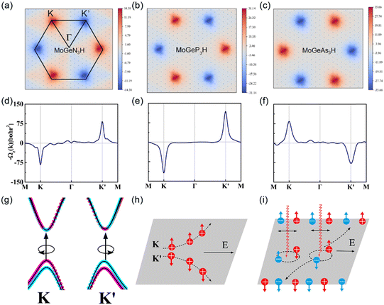
To further demonstrate the valleytronic properties of MoAZ3H ML, we also calculate the Berry curvatures of MAZ3H MLs based on the Kudo formula:43
 | (4) |
 , which are perpendicular to the electric field and move in opposite directions as shown in Fig. 5(h), leading to the valley Hall effect, which can also be excited by a linearly polarized optical field (Fig. 5(i)).
3.2 Piezoelectric properties
Next, we turn to explore both in-plane and out-of-plane piezoelectric effects in the MoAZ3H MLs with a unique Janus structure. For the 2D ML with P3m1 symmetry, the elastic and piezoelectric tensors be reduced into:46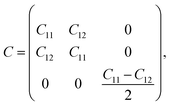 | (5) |
 | (6) |
 | (7) |
A uniaxial in-plane strain can induce both the in-plane and out-of-plane piezoelectric responses (e11/d11 ≠ 0 and e31/d31 ≠ 0), while a biaxial in-plane strain can only produce an out-of-plane piezoelectric response (e11/d11 = 0 but e31/d31 ≠ 0). Solving equation eik = dijCjk can derive the independent d11 and d31:
 | (8) |
Piezoelectric stress, strain and elastic tensors of MAZ3H MLs can be obtained from eqn (5)–(8) using the orthorhombic supercell (Fig. 1(a)), as listed in Table 2. Compared to MA2Z4 MLs, the Janus MAZ3H MLs break the reflection symmetry with respect to the central Mo atom due to the two different surface atoms in the vertical direction, leading to the non-zero e31/d31.
| C 11 | C 12 | e 11 | d 11 | e 31 | d 31 | |
|---|---|---|---|---|---|---|
| MoSiN3H | 375.96 | 120.89 | 4.146 | 1.622 | 0.290 | 0.058 |
| MoSiP3H | 159.70 | 44.38 | 7.583 | 6.576 | 0.257 | 0.126 |
| MoSiAs3H | 130.42 | 43.16 | 6.884 | 7.890 | 0.440 | 0.254 |
| MoGeN3H | 282.03 | 104.55 | 4.112 | 2.317 | 0.267 | 0.069 |
| MoGeP3H | 149.76 | 46.82 | 7.080 | 6.877 | 0.227 | 0.115 |
| MoGeAs3H | 128.56 | 42.15 | 7.429 | 8.598 | 0.418 | 0.325 |
| MoSi2N424 | — | — | 4.395 | 1.144 | — | — |
| MoGe2N424 | — | — | 4.218 | 1.050 | — | — |
| MoSiGeN424 | — | — | 5.116 | 1.494 | 0.087 | 0.014 |
It is firstly found that the piezoelectric coefficients e11/e31 of the MoSiN3H and MoGeN3H MLs are about 4.146/0.290 and 4.112/0.267 10−10 C m−1, respectively. Evidently, the two e11 coefficients are comparable to that of MoSi2N4 (MoGe2N4) ML (4.395 (4.218) 10−10 C m−1), while significantly smaller than that of MoSiGeN4 ML (5.116 10−10 C m−1).24 Apart from the smaller e11 of the MoSiAs3H ML than that of the MoGeAs3H ML, the MoSiZ3H MLs have larger e11 values than the MoGeZ3H systems. The size order of e11 is MoSiP3H > MoSiAs3H > MoSiN3H in the MoSiZ3H MLs, whereas the e11 of the MoGeZ3H ML increases with the increasing mass of Z element. The maximum e11 is 7.583 10−10 C m−1 for the MoSiP3H ML. The MoSiZ3H MLs have a slightly larger e31 than the MoGeZ3H systems, and the e31 values of the MoAN3H MLs are slightly larger than those of the MoAP3H MLs, while much smaller than those of the MoAAs3H MLs. In the e11/e31 of MoAN3H system, the electronic contribution has the opposite sign to the ionic contribution, while the electronic and ionic contributions dominate e11 and e31, respectively, as shown in Fig. 6(a) and (b), respectively. However, for the MoAP3H and MoAAs3H MLs, the electronic and ionic contributions have the same signs in e11/e31. This may be why the e11/e31 of the MoAN3H systems are smaller.
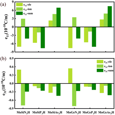 | ||
| Fig. 6 Ionic and electronic contributions of the piezoelectric coefficients (a) e11 and (b) e31 in the MoAZ3H ML, respectively. | ||
As discussed in previous research,30 the elastic constant of the MoAN3H ML is the largest in all of the MoAZ3H MLs, mostly larger than twice those of the other MoAZ3H MLs, and the MoAP3H ML has a slightly larger elastic constant than the MoAAs3H ML. Consequently, the values of C11 + C12 and C11 − C12 are decreasing with increasing atomic mass of A or Z element for the MoAZ3H ML. The piezoelectric coefficients d11/d31 are 1.62/0.058 pm V−1 for the MoSiN3H ML and 2.32/0.069 pm V−1 for the MoGeN3H ML, respectively, both much larger than that of the Janus MoSiGeN4 ML (1.49/0.014 pm V−1).24 In particular, the MoSiN3H and MoGeN3H MLs have larger d11 than the MoSi2N4 (1.14 pm V−1) and MoGe2N4 (1.05 pm V−1) MLs.24 As the atomic mass of A or Z element increases, the d11 value gets larger mainly because of the decreasing C11 − C12, on which changing the element Z has a greater effect. Hence, the MoGeAs3H ML has the maximum d11 of 8.60 pm V−1. Furthermore, for MoAZ3H MLs, increasing the atomic mass of Z element can greatly enhance the out-of-plane piezoelectric coefficient d31, mainly resulting from the decreasing C11 + C12. Increasing the atomic number of the A element can increase the d31 for the MoAN3H and MoAAs3H MLs whereas slightly reduce it for the MoAP3H ML. The maximun d31 is 0.325 pm V−1 for the MoGeAs3H ML.
The above discussion fully demonstrates that for MoA2Z4 MLs, forming MoAZ3H Janus MLs is beneficial for improving the in-plane piezoelectric response d11 values and also for inducing larger out-of-plane piezoelectric responses, larger than forming MoSiGeN4 Janus MLs.
3.3 Strain effect
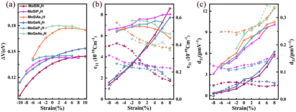
Strain is an effective way to control the electronic properties of 2D materials because they can withstand large strain due to the unique crystal structure.47 Below, we will investigate the strain effect on the spin-valley coupling and piezoelectric properties of Janus MoAZ3H MLs. Because this work only focuses on the semiconducting characteristics of the MoAZ3H MLs, it excludes the MoAZ3H MLs transforming to metals under strain. Table 1 reveals that the increasing atomic number of element A or Z in the MoAZ3H ML can gradually decrease the band gap, which would also narrow the strain range of maintaining the semiconducting properties. Thus, different strain ranges are considered for the MoAZ3H MLs with different components. In addition, it was revealed that Janus MoAZ3H MLs under zero strain exhibit good dynamic stability due to no imaginary frequency in the phonon spectra.30 We also calculate the phonon spectra of strained MoAZ3H MLs, and find that the phonon spectra have no imaginary frequency under the considered tensile strain and are prone to showing imaginary frequencies under large compressive strain. Fig. S4 (ESI†) presents the phonon spectra of the MoSiN3H, MoSiAs3H and MoGeN3H MLs under the tensile strain of 10%, in which there are no imaginary frequencies. This means that MoAZ3H MLs can sustain a larger tensile strain, whereas the compressive stress has a greater destructive force on the systems.Fig. 7(a) shows the strain tunable spin-valley coupling of the highest valence bands at the K/K′ points of MoAZ3H MLs. There is little change in the spin-valley couplings of the MoGeAs3H and MoGeP3H MLs under strain. Besides, for the other four MoAZ3H MLs, the spin-valley coupling is enhanced by the tensile strain, while weakened by the compressive strain, which indicates that strain can easily regulate spin-valley coupling strength, having potential applications in valleytronic devices. Fig. 7(b) and (c) present the responses of the piezoelectric coefficients to strain for the MoAZ3H MLs, which obviously illustrates that the piezoelectric coefficients can be easily tailored by strain. Overall, among the four piezoelectric coefficients, the most strain-regulated is d11, which basically increases and decreases with increasing tensile and compressive strains, respectively. The same strain regulation rule is followed by the e11 of the MoAN3H and MoAP3H MLs, whereas that of the MoAN3H MLs changes more significantly with strain. The e11 of the MoSiAs3H ML always reduces with both tensile and compressive strains, and that of the MoGeAs3H ML gradually decreases with strain from −2% to 8%. The e31 of the MoSiN3H ML gradually decreases with increasing tensile strain, and increases with increasing compressive strain until it reaches −6% and then decreases. For the MoGeN3H ML, the e31 has a maximum under the strain of −2%, decreasing with the strain from −2% to 8%. For the MoAP3H and MoAAs3H MLs, the e31 increases and decreases with the compressive and tensile strains, respectively, while the d31 is the opposite. In addition, the fluctuation range of d31 under strain for the six MoAZ3H MLs is not too large.
It is worth emphasizing that for the MoZ2 MLs with poor stability, the H atoms or the AZ layer passivating can make the system more stable.48,49 More importantly, this means that this can transform the system into a semiconductor with valleytronic characteristics. Thus, we propose to construct stable Janus MoAZ3H MLs by passivating the two surface Z atoms of MoZ2 MLs with one AZ layer and one H atomic layer, respectively, which endows the systems with the unique nature induced by asymmetry of the surface atoms other than the semiconducting and valley properties, such as photovoltaic properties and piezoelectricity.
4. Conclusions
To sum up, using first-principles calculations, we find that valleytronic and piezoelectric properties coexist in Janus MoAZ3H ML materials. The unique valleytronic properties arise from broken inversion symmetry and strong SOC effects, which brings about non-zero Berry curvatures with opposite signs at the K and K′ valleys and the valley Hall effects. In addition, the in-plane piezoelectric responses of Janus MoAZ3H MLs are stronger than those of the corresponding MoA2Z4 MLs. Surprisingly, the unique Janus structure induces obvious out-of-plane piezoelectric responses, and the out-of-plane piezoelectric coefficients e31/d31 are high up to 0.418 × 10⁻¹⁰ C m−1/0.325 pm V−1. More importantly, strain can tailor both the spin-valley coupling and piezoelectricity of MoAZ3H MLs. The coexisting valleytronic and piezoelectric properties win a wide application space in the valleytronics and energy conversion fields for the MoAZ3H MLs.Conflicts of interest
There are no conflicts of interest to declare.Acknowledgements
This work was supported partly by the National Natural Science Foundation of China (Grant No. 11804082, 12074102 and 11774078), and by the Doctoral Foundation of Henan Polytechnic University (B2018-37). All the calculations were carried out at the Center for High Performance Computing of Henan Polytechnic University.References
- D. Xiao, G.-B. Liu, W. Feng, X. Xu and W. Yao, Phys. Rev. Lett., 2012, 108(19), 196802 CrossRef PubMed.
- A. H. Castro Neto, F. Guinea, N. M. R. Peres, K. S. Novoselov and A. K. Geim, Rev. Mod. Phys., 2009, 81, 109–162 CrossRef CAS.
- J. R. Schaibley, H. Yu, G. Clark, P. Rivera, J. S. Ross, K. L. Seyler, W. Yao and X. Xu, Nat. Rev. Mater., 2016, 1, 16055 CrossRef CAS.
- B. Urbaszek and X. Marie, Nat. Phys., 2015, 11, 94–95 Search PubMed.
- F. Amet and G. Finkelstein, Nat. Phys., 2015, 11, 989–990 Search PubMed.
- X. Li and G. Moody, Nat. Phys., 2017, 13, 9–10 Search PubMed.
- H. Yu and W. Yao, Nat. Mater., 2017, 16, 876–877 CrossRef CAS PubMed.
- F. Zhang, Nat. Phys., 2018, 14, 111–113 Search PubMed.
- L. Cao, G. Zhou, Q. Wang, L. K. Ang and Y. S. Ang, Appl. Phys. Lett., 2021, 118, 013116 Search PubMed.
- B. Liu, Natl. Sci. Rev., 2020, 7, 1841–1842 CrossRef PubMed.
- S. Li, W. Wu, X. Feng, S. Guan, W. Feng, Y. Yao and S. Yang, Phys. Rev. B, 2020, 102, 235435 CrossRef CAS.
- K. Mak, C. Lee, J. Hone, J. Shan and T. Heinz, Phys. Rev. Lett., 2010, 105, 136805 CrossRef PubMed.
- K. F. Mak, K. L. McGill, J. Park and P. L. McEuen, Science, 2014, 344, 1489–1492 CrossRef CAS PubMed.
- Y. Shao, Y. Fang, T. Li, Q. Wang, Q. Dong, Y. Deng, Y. Yuan, H. Wei, M. Wang, A. Gruverman, J. Shield and J. Huang, Energy Environ. Sci., 2016, 9, 1752–1759 RSC.
- C. Yang, Z. Song, X. Sun and J. Lu, Phys. Rev. B, 2021, 103, 035308 CrossRef CAS.
- J.-S. Yang, L. Zhao, S.-Q. Li, H. Liu, L. Wang, M. Chen, J. Gao and J. Zhao, Nanoscale, 2021, 13, 5479–5488 RSC.
- X. Y. Feng, X. L. Xu, Z. L. He, R. Peng, Y. Dai, B. B. Huang and Y. D. Ma, Phys. Rev. B, 2021, 104, 075421 CrossRef CAS.
- Q. R. Cui, Y. M. Zhu, J. H. Liang, P. Cui and H. X. Yang, Phys. Rev. B, 2021, 103, 085421 CrossRef CAS.
- Y. Duan, X. Zhao, M. Sun and H. Hao, Ind. Eng. Chem. Res., 2021, 60, 1071–1095 CrossRef CAS.
- V. T. T. Vi, T. P. T. Linh, C. Q. Nguyen and N. N. Hieu, Adv. Theory Simul., 2022, 5, 2200499 CrossRef CAS.
- Y. Yu, J. Zhou, Z. Guo and Z. Sun, ACS Appl. Mater. Interfaces, 2021, 13, 28090–28097 CrossRef CAS PubMed.
- M.-Y. Liu, Y. He, X. Li and K. Xiong, Phys. Chem. Chem. Phys., 2023, 25, 7278–7288 RSC.
- L. Wu, W. Zhou, D. Zhang and F. Ouyang, J. Phys.: Conf. Ser., 2022, 2263, 012014 CrossRef.
- S.-D. Guo, W.-Q. Mu, Y.-T. Zhu, R.-Y. Han and W.-C. Ren, J. Mater. Chem. C, 2021, 9, 2464–2473 RSC.
- S. Sheoran, A. Phutela, R. Moulik and S. Bhattacharya, J. Phys. Chem. C, 2023, 127, 11396–11406 CrossRef CAS.
- S.-D. Guo, W.-Q. Mu, J.-H. Wang, Y.-X. Yang, B. Wang and Y.-S. Ang, Phys. Rev. B, 2022, 106, 064416 CrossRef CAS.
- Y. Li, M. Lan, S. Wang, T. Huang, Y. Chen, H. Wu, F. Li and Y. Pu, Phys. Chem. Chem. Phys., 2023, 25, 15676–15682 RSC.
- R. T. Sibatov, R. M. Meftakhutdinov and A. I. Kochaev, Appl. Surf. Sci., 2022, 585, 152465 CrossRef CAS.
- P. T. L. Tran, N. V. Hieu, H. Bui D, Q. N. Cuong and N. N. Hieu, Nanoscale Adv., 2023, 5, 3104–3113 RSC.
- X. Cai, G. Chen, R. Li, W. Yu, X. Yang and Y. Jia, Phys. Chem. Chem. Phys., 2023, 25, 29594–29602 RSC.
- G. Kresse and J. Hafner, Phys. Rev. B: Condens. Matter Mater. Phys., 1993, 47, 558–561 CrossRef CAS PubMed.
- P. Hohenberg and W. Kohn, Phys. Rev., 1964, 136, B864–B871 CrossRef.
- J. P. Perdew, K. Burke and M. Ernzerhof, Phys. Rev. Lett., 1996, 77, 3865–3868 CrossRef CAS PubMed.
- J. Heyd, G. E. Scuseria and M. Ernzerhof, J. Chem. Phys., 2003, 118, 8207–8215 CrossRef CAS.
- N. Marzari, A. A. Mostofi, J. R. Yates, I. Souza and D. Vanderbilt, Rev. Mod. Phys., 2012, 84, 1419–1475 CrossRef CAS.
- T. Fukui, Y. Hatsugai and H. Suzuki, J. Phys. Soc. Japan., 2005, 74, 1674–1677 CrossRef CAS.
- V. Wang, N. Xu, J.-C. Liu, G. Tang and W.-T. Geng, Comput. Phys. Commun., 2021, 267, 108033 CrossRef CAS.
- H. Ai, D. Liu, J. Geng, S. Wang, K. H. Lo and H. Pan, Phys. Chem. Chem. Phys., 2021, 23, 3144–3151 RSC.
- X. Feng, X. Xu, Z. He, R. Peng, Y. Dai, B. Huang and Y. Ma, Phys. Rev. B, 2021, 104, 075421 CrossRef CAS.
- Y. Xu, H. Liu, Y. Dai, B. Huang and W. Wei, Appl. Phys. Lett., 2023, 122, 242404 CrossRef CAS.
- Y. Ma, L. Kou, A. Du, B. Huang, Y. Dai and T. Heine, Phys. Rev. B, 2018, 97, 035444 CrossRef CAS.
- M. K. Mohanta and A. De Sarkar, Phys. Rev. B, 2020, 102, 125414 CrossRef CAS.
- D. J. Thouless, M. Kohmoto, M. P. Nightingale and M. den Nijs, Phys. Rev. Lett., 1982, 49, 405–408 CrossRef CAS.
- D. Xiao, G.-B. Liu, W. Feng, X. Xu and W. Yao, Phys. Rev. Lett., 2012, 108, 196802 CrossRef PubMed.
- D. Xiao, M.-C. Chang and Q. Niu, Rev. Mod. Phys., 2010, 82, 1959–2007 CrossRef CAS.
- M. Blonsky, H. L. Zhuang, A. K. Singh and R. G. Hennig, ACS Nano, 2015, 9(10), 9885–9891 CrossRef CAS PubMed.
- X. H. Peng, Q. Wei and A. Copple, Phys. Rev. B: Condens. Matter Mater. Phys., 2014, 90, 085402 CrossRef CAS.
- J. Yuan, Q. Wei, M. Sun, X. Yan, Y. Cai, L. Shen and U. Schwingenschlgl, Phys. Rev. B, 2022, 105, 195151 CrossRef CAS.
- Y. Wang and Y. Ding, J. Mater. Chem. C, 2016, 4, 7485–7493 RSC.
Footnote |
| † Electronic supplementary information (ESI) available. See DOI: https://doi.org/10.1039/d4tc00188e |
| This journal is © The Royal Society of Chemistry 2024 |


