 Open Access Article
Adjustable 1D ferroelectricity and ferrielectricity in faceted GeSe nanotubes†
Shixin
Song
,
Churen
Gui
,
Shuai
Dong
 ,
Dan
Liu
 * and
Jie
Guan
 *
*
Key Laboratory of Quantum Materials and Devices of Ministry of Education, School of Physics, Southeast University, Nanjing, 211189, China. E-mail: liudan2@seu.edu.cn; guanjie@seu.edu.cn
First published on 5th April 2024
Abstract
Dimensionality reduction of ferroelectric (FE) materials is a pressing task at present due to the increasingly urgent need for miniaturized devices. Here, a set of unprecedented stable one-dimensional (1D) faceted GeSe nanotubes (GNTs) was explored and predicted to be synthesizable within carbon nanotubes. All the GNTs exhibit an axial FE polarization induced by broken inversion symmetry and the polarization intensity can be adjusted by altering their radial dimensions. Both the polarization intensity and Curie temperature can be enhanced by forming double-walled (DW) GNT structures. Different stacking configurations enable DW GNTs to exhibit switchable FE and ferrielectric charge orders. Our results enrich the family of 1D FE systems and provide new insights into the manipulation of 1D FEs.
1 Introduction
Ferroelectric (FE) materials, characterized by two or more spontaneously polarized states that can be switched by an external electric field, have been widely explored to design functional devices, such as field-effect transistors (FETs), nonvolatile memories, sensors, and optoelectronic devices.1–4 With the rapid development of nanotechnology, there is an increasingly urgent need for miniaturized devices and low-dimensional materials. However, dimensionality reduction usually suppresses the ferroelectricity of FE materials due to the enhanced depolarization field as well as the increased presence of dangling bonds and surface reconstructions.5–8Over the past decade, the rapid emergence of van der Waals (vdW) layered two-dimensional (2D) materials has facilitated the extensive exploration of inherent atomic-thin FE materials, leading to significant breakthroughs in their applications in low-dimensional devices.9–15 Compared to 2D materials, one-dimensional (1D) structures are constrained in two radial dimensions and only extend along the axial direction. The weak inter-chain coupling allows each individual 1D chain to function as an independent electric polarization unit, indicating promising applications of 1D FE arrays in high-density memories and high-resolution sensors.16,17 However, the exploration of 1D FEs is currently significantly less extensive than that of 2D systems.
Numerous efforts have been devoted to the fabrication of the 1D limit for traditional bulk FE materials in experiments, including nanowires, nanorods, nanobelts, and nanotubes.16,18–20 However, these 1D structures are usually larger than 10 nm in radial size and are susceptible to the depolarization field and surface states. Theoretically, several atomic-scale 1D FE structures isolated from vdW crystals made of 1D building blocks have been discussed,17,21–23 yet the exfoliation of 1D structures remains a challenge in experiments.
Recently, diverse 1D atomic-scale materials have been successfully achieved using carbon nanotubes (CNTs) as confining templates.24–28 In particular, 1D group-IV monochalcogenides, such as SnSe and SnTe, were synthesized inside CNTs and the structures can be regulated by changing the diameter of template CNTs.26–28 Inspired by experimental works, the FE performance of 1D group-IV monochalcogenides (MX, M = Si, Ge, and Sn and X = S, Se, and Te) and their isoelectric structures has been investigated and the rocksalt-like nanowire structures were found to be promising for nanoscale FE applications.29–31 On the other hand, due to the competition between covalent and ionic atomic bonding, group-IV monochalcogenides can form a variety of 2D FE structural phases, including non-collinear ferrielectric (FiE) and antiferroelectric (AFE) structures.9,32–36 The present studies on the application of this family in 1D ferroelectrics, however, are still in their infancy. Exploring additional structural possibilities and modulation approaches in 1D FE materials remains a pressing task at present and will greatly contribute to the development of nanoscale FE devices with broad applications.
In this work, through comprehensive density functional theory (DFT) calculations, we explored a set of unprecedented 1D faceted GeSe nanotubes (GNTs). The stability of the GNTs was confirmed through calculated cohesive energy, phonon spectra, and ab initio molecular dynamics (AIMD) simulations. An axial FE polarization was found to be induced by the inversion symmetry broken in the ground state of the GNTs. The net electric polarization, energy barrier for the phase transition, and Curie temperature (TC) were estimated for the selected GNTs. Furthermore, double-walled (DW) GNT structures were also constructed and predicted to have both FE and FiE stacking configurations, resulting in multiple stable phases and variable net polarizations. The adjustable FE polarization, semiconducting feature, and potential synthesis with CNT templates make both single-walled (SW) and DW GNTs highly promising and feasible for applications in nanoscale FE devices.
2 Computational techniques
To understand the structural, electronic, and polar properties of GeSe, we performed ab initio DFT calculations based on the projector augmented wave (PAW) pseudopotentials and the Perdew–Burke–Ernzerhof (PBE) format, as implemented in the Vienna ab initio Simulation Package (VASP) code.37–39 For 1D systems, a vacuum region with 20 Å thickness along two radial directions was adopted to avoid the interactions between periodic images. All the structures were fully relaxed by using the conjugate-gradient method until the Hellman–Feynman force on each atom was smaller than 0.01 eV Å−1.40 The electronic wave function was expanded on a plane-wave basis set with a cutoff energy of 500 eV. The reciprocal space was sampled by a fine grid of 1 × 1 × 6 k points in the Brillouin zone, employing the scheme introduced by Monkhorst–Pack.41 The vdW correction of the DFT-D2 method was considered when dealing with the combination of layers or nanotubes.42The phonon spectra were calculated using the density functional perturbation theory approach,43–45 as implemented in the PHONOPY code.46 Canonical AIMD simulations with the NVT ensemble at different temperatures were performed and each simulation lasted longer than 15 ps with a time step of 3 fs for a 1 × 1 × 4 supercell, which included more than 96 atoms. The symmetry analysis was performed based on the PHONOPY package and Bilbao crystallographic server.47–49
3 Results and discussion
3.1 Structure and stability
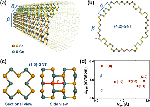
Unlike ordinary nanotubes formed by rolling up the corresponding monolayers, the faceted GNT structures presented in this study are constructed by laterally connecting the different stable allotropes of layered GeSe, namely, β-GeSe34 and δ-GeSe.35 As presented in Fig. S1 (ESI†), the monolayers of β- and δ-GeSe share the underlying hexagonal lattice, allowing them to be connected in a single layer with little deformation.A typical GNT is formed by connecting laterally β- and δ-GeSe nanoribbons along their armchair edges, shown in Fig. 1a. The obtained nanotube has a C4 symmetry and an octagonal cross-section, shown in Fig. 1b. Either β- or δ-GeSe nanoribbons in the four identical 90° segments may have a different width, giving rise to a number of different structures, as presented in Fig. S2 (ESI†). Since the width of the nanoribbons can be decided by W = N|![[a with combining right harpoon above (vector)]](https://www.rsc.org/images/entities/i_char_0061_20d1.gif) 2|, we may characterize a GNT as (m,n)-GNT, where N can be a positive integer or zero,
2|, we may characterize a GNT as (m,n)-GNT, where N can be a positive integer or zero, ![[a with combining right harpoon above (vector)]](https://www.rsc.org/images/entities/i_char_0061_20d1.gif) 2 is the lattice vector along the zigzag direction in 2D β- or δ-GeSe (shown in Fig. S1, ESI†), and m/n is the value of N for β-/δ-GeSe nanoribbons. In this way, the nanotube in shown Fig. 1a and b can be identified as a (4,2)-GNT. Notably, the narrowest GNT with a square of 4 atoms in the cross-section, which has been discussed in previous works as the rocksalt-like nanowire,27,29,31 can be identified as a (0,0)-GNT (Fig. S2a, ESI†).
2 is the lattice vector along the zigzag direction in 2D β- or δ-GeSe (shown in Fig. S1, ESI†), and m/n is the value of N for β-/δ-GeSe nanoribbons. In this way, the nanotube in shown Fig. 1a and b can be identified as a (4,2)-GNT. Notably, the narrowest GNT with a square of 4 atoms in the cross-section, which has been discussed in previous works as the rocksalt-like nanowire,27,29,31 can be identified as a (0,0)-GNT (Fig. S2a, ESI†).
Ordinary rolled-up nanotubes usually have large strain energy when the radii are small, according to continuum elasticity theory.50 In contrast, the GNTs here are much more stable since virtually no deformation is required to form a faceted nanotube. The cohesive energies of the five narrowest GNTs were calculated to investigate their stability and the results are shown in Fig. 1d. Our cohesive energy here is defined as Ecoh = EGNT − NGeEGe − NSeESe, where EGNT, EGe, and ESe represent the total energies of the GNT structure per formula unit (f.u.), the isolated Ge atom, the isolated Se atom and NGe and NSe represent the number of Ge and Se atoms in one f.u. of the GNT, respectively.
We find that cohesive energies of all the GNTs proposed in this study are more negative than those of the experimentally realized rocksalt-like nanowires, i.e., (0,0)-GNTs, indicating a higher stability. As expected, the values of Ecoh for the GNTs are nearly independent of the radius and fall within the range delimited by the Ecoh of the pure planar components β- and δ-GeSe monolayers, suggesting negligible strain energy for these faceted nanotubes. The specific values of Ecoh for the selected structures are listed in Table 1.
| Structure | c (Å) | E coh (eV per f.u.) | λ (Å)−1 | P 1 (10−19 C) | P 2 (pC cm−1) | P 3 (C m−2) |
|---|---|---|---|---|---|---|
| (0,0) | 5.82 | −6.860 | 1.37 | 1.48 | 2.00 | 4.33 |
| (1,0) | 5.79 | −7.024 | 4.14 | 4.72 | 2.49 | 1.75 |
| (2,0) | 5.84 | −7.017 | 6.85 | 6.75 | 2.04 | 0.83 |
| (3,0) | 5.84 | −7.012 | 9.58 | 9.21 | 1.93 | 0.57 |
| (1,1) | 5.81 | −7.067 | 9.64 | 10.58 | 2.52 | 0.86 |
| β | 5.84 | −7.088 | — | — | 1.50 | 0.77 |
| δ | 5.76 | −6.994 | — | — | 2.49 | 0.93 |
The relatively high energetic stability of the GNTs indicates a reasonable prospect for their preparation in appropriate confining templates such as suitable CNTs. The stability of the GNTs is also confirmed by phonon spectrum calculations and AIMD simulations for selected structures, which will be discussed later.
3.2 Ferroelectricity
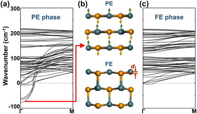
Since the 1D GNTs share the same structural morphology, we take (1,0)-GNTs, shown in Fig. 1c, as an example to investigate their ferroelectric characters. The FE phase (1,0)-GNT with an axial polarization can be derived from the non-polarized paraelectric (PE) phase, as shown in Fig. 2b. The phonon dispersion of both the PE and FE phases was calculated and the results are plotted in Fig. 2a and c. We find that imaginary frequencies exist at the Γ point in the Brillouin zone of the PE phase. The vibration mode of the lowest imaginary frequency refers to the distortion with opposite displacements of Ge and Se atoms along the axial direction, as shown by the arrows in the upper panel of Fig. 2b. These opposite displacements break the spatial inversion symmetry along the axial direction of the PE phase and lead to the FE phase (1,0)-GNT (lower panel of Fig. 2b). When taking the sublattice of all the Se atoms as a reference, the Ge atom sublattice exhibits a unified displacement (d) along the axial direction in the FE phase. Irreducible representation (irrep) analysis shows that the space group of the PE phase is P42/mcm(132) and the Γ3− irrep at the Γ point corresponds to FE distortion. When the Γ3− mode condenses, the PE phase transitions to the FE phase with a space group of P42cm(101).Besides the largest imaginary frequency, all the other modes with smaller imaginary frequencies in the PE phase refer to a mixture of AFE and FE distortions along the axial direction. In the phonon spectra of the FE phase, essentially no imaginary frequencies are found, indicating the dynamic stability of (1,0)-GNTs. We should note that the tiny “U” shape dispersion (smaller than −4.31 cm−1) near the Γ point here is common among low-dimensional systems.51
The electric polarizations of all the five narrowest GNTs were calculated by the Berry phase method. In Fig. 3a–c, we have shown the obtained values of linear polarization (P1), when considering the GNTs as 1D systems, areal polarization (P2), when considering them as deformed 2D systems, and bulk polarization (P3), when considering them as 3D systems. We find that the values of P1 are typically directly proportional to the linear density of the atomic number (λ). The values of P2 are almost independent of λ and close to those for their 2D counterparts, β- and δ-GeSe. The values of P3, however, are inversely proportional to λ due to the lower bulk atomic density in the wider GNTs. Notably, the smallest value of P3 for (3,0)-GNTs (0.57 C m−2) here is still larger than the experimental value of bulk BaTiO3 (0.26 C m−2).52 The detailed results of electric polarizations are listed in Table 1.
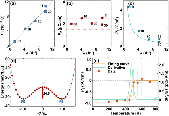 | ||
| Fig. 3 The (a) linear polarization P1, (b) areal polarization P2, and (c) bulk polarization P3 of the selected GNTs as a function of the line density of atoms λ. (d) Total energy as a function of the relative value of atomic displacement d, which is shown in Fig. 2(b), for (1,0)-GNTs. (e) The areal polarization P2 (left axis) and pyroelectric response dP2/dT (right axis) as a function of temperature based on ab initio molecular dynamics (AIMD) simulations. | ||
To examine the phase transition of FE GNTs, we depict in Fig. 3d the energy curve of interpolated structures for (1,0)-GNT with different relative atomic displacements. The two valleys in the double-well-shape curve correspond to the FE and FE′ phases with opposite polarizations, and the local maximum in the middle corresponds to the PE phase. The energy barrier between the two degenerated FE phases is 24.5 meV per f.u., which is comparable to the corresponding values (23.6 meV per f.u.) for the (0,0)-GNT.31 This value is closely related to the transition temperature between the FE and PE phase.
AIMD simulations were carried out at temperatures ranging from 200 K to 700 K to investigate the phase transition of (1,0)-GNT and the areal polarization P2 calculated using the point charge model as a function of temperature is plotted in Fig. 3e. We find that the FE polarization is maintained up to 450 K and the value of TC is around 475 K, indicating the robust ferroelectricity at room temperature. The pyroelectric response dP2/dT was also calculated and a peak value of 2 pC k−1 m−1 was found near 475 K. AIMD simulations were also carried out for other GNT structures at room temperature and the results are shown in Fig. S3 (ESI†). We find that all the selected GNTs exhibit structural thermodynamic stability at 300 K. However, the FE polarization is only maintained in (0,0)- and (1,1)-GNTs but not in (2,0)- and (3,0)-GNTs, indicating that the TC value is above 300 K for (0,0)- and (1,1)-GNTs and below 300 K for the other two.
3.3 Double-wall nanotubes
It is known that in most cases, a carbon nanotube exists in the form of a multi-walled nanotube, which is a concentric arrangement of two or more SW nanotubes.53 Similarly, nested SW GNTs with different sizes can also form a multi-walled GNT. Here we constructed four DW GNT structures including (0,0)@(2,0)-, (0,0)@(3,0)-, (0,0)@(1,1)-, and (1,0)@(3,0)-GNTs, as shown in Fig. 4. We find that all the selected DW GNTs have FE-stacking ground states with both inner and outer tubes exhibiting polarizations in the same direction. In addition, the three (m,n)@(m + 2,n)-GNTs also have meta-stable FiE states with the inner and outer tubes exhibiting polarizations in opposite directions.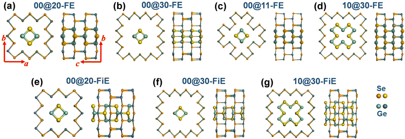 | ||
| Fig. 4 Equilibrium structures of DW-GNTs with (a)–(d) FE stacking and (e)–(g) FiE stacking. The FiE-stacking (0,0)@(1,1)-GNT configuration is not stable. | ||
The binding energy (Eb), defined by the total energy of a DW GNT minus the sum of the total energies for the inner and outer SW GNTs, was calculated and is summarized in Table 2. We find that all the calculated Eb values are negative, indicating the energetic stability of DW GNTs. For (0,0)@(2,0)- and (1,0)@(3,0)-GNTs, the FE-stacking configurations have more negative Eb than the FiE-stacking ones. The Eb values for FE- and FiE-stacking in (0,0)@(3,0)-GNTs exhibit no difference and are both significantly smaller in absolute value than the other DW GNTs. This is due to their large inter-wall distance and consequently weak inter-wall interaction. The Eb values around −0.1 eV per f.u. for the DW GNTs except for (0,0)@(3,0)-GNTs are close to the binding energies for the bilayers of 2D β- (−0.153 eV per f.u.) and δ-GeSe (−0.114 eV per f.u.). These specific types of DW GNTs, including (m,n)@(m + 2,n)- and (m,n)@(m + 1,n+1)-GNTs, also exhibit the most negative binding energy achievable.
| Structure | c (Å) | E b (eV per f.u.) | P 1 (10−19 C) | |
|---|---|---|---|---|
| (0,0)@(2,0) | FE | 5.77 | −0.111 | 9.24 |
| FiE | 5.88 | −0.096 | 6.50 | |
| (0,0)@(3,0) | FE | 5.82 | −0.034 | 10.37 |
| FiE | 5.83 | −0.034 | 7.29 | |
| (0,0)@(1,1) | FE | 5.74 | −0.106 | 11.88 |
| (1,0)@(3,0) | FE | 5.75 | −0.132 | 15.31 |
| FiE | 5.89 | −0.122 | 6.51 |
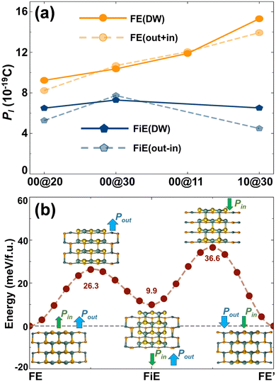
The net electric polarizations of the selected DW GNTs were calculated and are shown in Fig. 5a. We find that the total linear polarization P1 for FE-stacking DW GNTs approximates the summation of P1 for the isolated outer and inner SW tubes, while for the FiE-stacking ones, it approximates the difference of P1 between the isolated outer and inner tubes. The direction of the net polarization for an FiE-stacking DW GNT is the same as that of the outer tube since the outer tube has larger values of λ and P1 in comparison to the inner tube. The detailed values of P1 are also listed in Table 2. The polarization characters of the DW GNTs are significantly different from those of multi-layer 2D FE systems with in-plane polarizations. For instance, the in-plane net polarization in the α phase of 2D MXs disappears in even-number-layer structures due to the restored inversion symmetry in the AFE-stacking configuration.9
To examine the durability of DW GNTs, we also conducted AIMD simulations on the selected DW GNTs, as shown in Fig. S4 (ESI†). We find that all the calculated DW GNTs exhibit structural thermodynamic stability at 300 K. More interestingly, unlike SW (2,0)- and (3,0)-GNTs which exhibit a PE character, the FE-stacking (0,0)@(2,0)-GNTs and (1,0)@(3,0)-GNTs maintain the FE polarizations at 300 K. For the FiE-stacking phase at 300 K, (1,0)@(3,0)-GNTs can maintain the FiE polarization while (0,0)@(2,0)-GNTs will transition to the FE-stacking configuration. Nevertheless, the FiE-stacking (0,0)@(2,0)-GNTs can still maintain the configuration at 200 K. The results indicate that the inter-wall interaction in a DW GNT can effectively suppress the thermal disturbance. The superposable polarization and enhanced thermal stability make the DW GNTs a more promising prospect in applications compared to the SW GNTs.
In comparison to conventional FE materials, the DW GNTs with both FE and FiE phases can provide extra stable charge orders, including FE, FE′, FiE, and FiE′ phases, corresponding to different information storage states. This distinctive feature enables DW GNT-based memories to achieve higher storage density and superior performance. In Fig. 5b, we take (1,0)@(3,0)-GNTs as an example to illustrate the potential transition passway between the FiE and FE phases. The FiE phase can be achieved from the FE phase by flipping the polarization of the inner tube with an energy barrier of 26.3 meV per f.u. or from the FE' phase by flipping the polarization of the outer tube with a barrier of 36.6 meV per f.u. The FiE′ phase can also be obtained through a similar process.
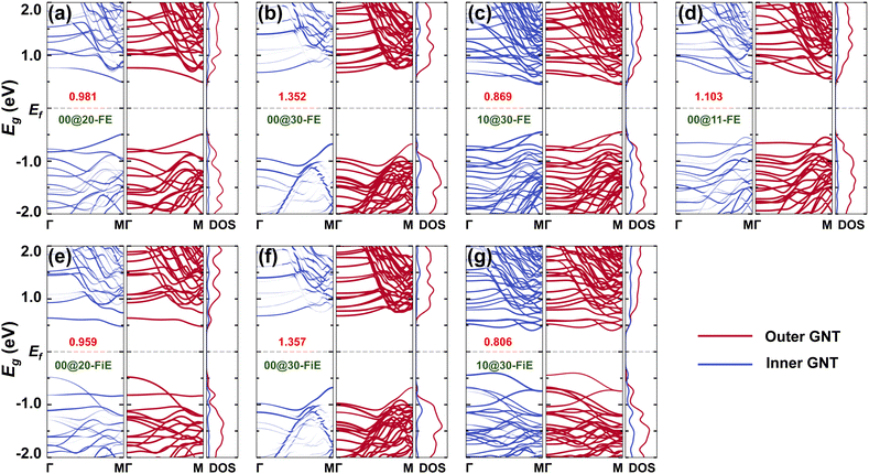
Electronic structures were investigated for the selected GNTs. The DFT-PBE band structure and the associated density of states (DOS) are shown in Fig. 6 and Fig. S5 (ESI†). It is found that all the GNTs are semiconducting. The DW GNTs exhibit larger band gaps in the FE-stacking phase than in the FiE-stacking phase and all the DW GNTs exhibit narrower band gaps in comparison to their isolated SW counterparts. The shrinkage of band gaps is mainly due to the inter-wall interaction present in the DW GNTs. The inter-wall interaction can also be distinguished in the differential charge density distribution observed in the combined DW GNTs (Fig. S6, ESI†), where significant charge accumulations are found in between the walls. The appropriate band gaps allow the switching of polarizations in the SW and DW GNTs through the application of an external electric field.
To better investigate the band alignment in the DW GNTs, the band structure and DOS were projected onto the inner and outer tubes, respectively, as shown in Fig. 6. We observe significant band overlap at the band edges between the inner and outer components in the DW GNTs, due to the inter-wall interaction (Fig. S6, ESI†). In particular, both FE- and FiE-stacking (0,0)@(3,0)-GNTs, which have relatively weak inter-wall interactions, exhibit a typical type II heterojunction with the valence band maximum (VBM) dominated by the inner tube and the conduction band minimum (CBM) dominated by the outer tube.
3.4 Preparation with CNT templates
Encouraged by the successful structural regulation of 1D group-IV monochalcogenides inside CNTs, including rocksalt-like nanowires of SnSe26 and SnTe27 which share the same structure as (0,0)-GNTs, GNTs with different sizes are considered highly promising for synthesis within CNT templates of varying diameters. In Fig. 7, we take (1,0)-GNTs as a representative example to investigate the GNT@CNT coaxial heterostructures. Structures with a (1,0)-GNT inside (10,10)-, (11,11)-, and (12,12)-CNTs were constructed, yielding corresponding binding energies of 53, −134, and −108 meV per atom, respectively. The most negative value of binding energy indicates that the (11,11)-CNT with a diameter of 14.94 Å is a suitable template for synthesizing the 1D (1,0)-GNT structure.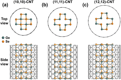 | ||
| Fig. 7 Equilibrium structures of the coaxial heterostructures with (1,0)-GNTs inside (a) (10,10)-, (b) (11,11)-, and (c) (12,12)-CNTs in both top and side views. | ||
4 Conclusion
In conclusion, we have proposed a novel class of 1D FE materials, named faceted GeSe nanotubes, by laterally joining the β and δ phases of GeSe nanoribbons. Our ab initio DFT calculations show that the formed GNTs are nearly as stable as the pure planar components, due to the negligible strain energy caused by the structural deformations. Axial FE polarizations exist in all the calculated GNTs and the linear polarizations can be adjusted by varying the size of the tubes. The renormalized areal polarizations ranging from 1.93–2.52 pC cm−1 are determined by the Berry phase method in the calculated GNTs, which are comparable to those of the 2D GeSe structures. For (1,0)-GNTs, an energy barrier of 24.5 meV per f.u. is found for the phase transition between degenerated FE phases and the corresponding TC from the FE to the PE phase is 475 K based on AIMD simulations.The GNTs can also exist in the form of DW nanotubes with an FE- or FiE-stacking configuration and exhibit different net polarizations. The DW GNTs featuring both FE and FiE phases provide extra information storage states and achieve higher density when applied in memories. The semiconducting properties of GNTs enable polarization switching through external electric fields. Finally, there is a strong likelihood that GNTs of different sizes could be synthesized within CNT templates of varying diameters. Our work has significantly enriched the family of 1D FE materials and provided new insights into the manipulation of 1D FEs.
Conflicts of interest
There are no conflicts to declare.Acknowledgements
This study was supported by the National Natural Science Foundation of China (grant no. 62274028 and 12204095), the Natural Science Foundation of Jiangsu Province (grant no. BK20210198), the High Level Personnel Project of Jiangsu Province (grant no. JSSCBS20220120), and the Zhishan Foundation of Southeast University (grant no. 2242023R10006). We thank the Big Data Computing Center of Southeast University for providing facility support for performing calculations.Notes and references
- K. M. Rabe, C. H. Ahn and F. M. Triscone, Physics of Ferroelectrics: A Modern Perspective, Spinger, 2007 Search PubMed.
- S. Mathews, R. Ramesh, T. Venkatesan and J. Benedetto, Science, 1997, 276, 238–240 CrossRef CAS PubMed.
- J. F. Scott, Science, 2007, 315, 954–959 CrossRef CAS PubMed.
- A. Q. Jiang, C. Wang, K. J. Jin, X. B. Liu, J. F. Scott, C. S. Hwang, T. A. Tang, H. B. Lu and G. Z. Yang, Adv. Mater., 2011, 23, 1277–1281 CrossRef CAS PubMed.
- J. Junquera and P. Ghosez, Nature, 2003, 422, 506–509 CrossRef CAS PubMed.
- D. D. Fong, G. B. Stephenson, S. K. Streiffer, J. A. Eastman, O. Auciello, P. H. Fuoss and C. Thompson, Science, 2004, 304, 1650–1653 CrossRef CAS PubMed.
- C. H. Ahn, K. M. Rabe and J.-M. Triscone, Science, 2004, 303, 488–491 CrossRef CAS PubMed.
- D. Lee, H. Lu, Y. Gu, S.-Y. Choi, S.-D. Li, S. Ryu, T. R. Paudel, K. Song, E. Mikheev, S. Lee, S. Stemmer, D. A. Tenne, S. H. Oh, E. Y. Tsymbal, X. Wu, L.-Q. Chen, A. Gruverman and C. B. Eom, Science, 2015, 349, 1314–1317 CrossRef CAS.
- R. Fei, W. Kang and L. Yang, Phys. Rev. Lett., 2016, 117, 097601 CrossRef PubMed.
- K. Chang, J. Liu, H. Lin, N. Wang, K. Zhao, A. Zhang, F. Jin, Y. Zhong, X. Hu, W. Duan, Q. Zhang, L. Fu, Q.-K. Xue, X. Chen and S.-H. Ji, Science, 2016, 353, 274–278 CrossRef CAS PubMed.
- L. You, F. Liu, H. Li, Y. Hu, S. Zhou, L. Chang, Y. Zhou, Q. Fu, G. Yuan, S. Dong, H. J. Fan, A. Gruverman, Z. Liu and J. Wang, Adv. Mater., 2018, 30, 1803249 CrossRef PubMed.
- W. Ding, J. Zhu, Z. Wang, Y. Gao, D. Xiao, Y. Gu, Z. Zhang and W. Zhu, Nat. Commun., 2017, 8, 14956 CrossRef CAS PubMed.
- J. Y. Yang, M. J. Yeom, Y. Park, J. Heo and G. Yoo, Adv. Electron. Mater., 2021, 7, 2100306 CrossRef CAS.
- L. Qi, S. Ruan and Y.-J. Zeng, Adv. Mater., 2021, 33, 2005098 CrossRef CAS PubMed.
- Z. Guan, H. Hu, X. Shen, P. Xiang, N. Zhong, J. Chu and C. Duan, Adv. Electron. Mater., 2020, 6, 1900818 CrossRef CAS.
- Z. Hu, M. Tian, B. Nysten and A. M. Jonas, Nat. Mater., 2009, 8, 62–67 CrossRef CAS PubMed.
- L. Zhang, C. Tang, S. Sanvito and A. Du, npj Comput. Mater., 2021, 7, 135 CrossRef CAS.
- J. H. Jung, C.-Y. Chen, B. K. Yun, N. Lee, Y. Zhou, W. Jo, L.-J. Chou and Z. L. Wang, Nanotechnology, 2012, 23, 375401 CrossRef PubMed.
- Y. Hu, F. Florio, Z. Chen, W. A. Phelan, M. A. Siegler, Z. Zhou, Y. Guo, R. Hawks, J. Jiang, J. Feng, L. Zhang, B. Wang, Y. Wang, D. Gall, E. F. Palermo, Z. Lu, X. Sun, T.-M. Lu, H. Zhou, Y. Ren, E. Wertz, R. Sundararaman and J. Shi, Sci. Adv., 2020, 6, eaay4213 CrossRef CAS PubMed.
- L. Liang, X. Kang, Y. Sang and H. Liu, Adv. Sci., 2016, 3, 1500358 CrossRef PubMed.
- L.-F. Lin, Y. Zhang, A. Moreo, E. Dagotto and S. Dong, Phys. Rev. Mater., 2019, 3, 111401 CrossRef CAS.
- F. Zhang, W. Chen, Y. Zhang and H. Yin, Phys. Chem. Chem. Phys., 2023, 25, 6112–6120 RSC.
- W. Sun, N. Ding, J. Chen, H.-P. You, J. Peng, S.-S. Wang and S. Dong, Phys. Rev. Mater., 2022, 6, 104404 CrossRef CAS.
- J. Zhang, C. Fu, S. Song, H. Du, D. Zhao, H. Huang, L. Zhang, J. Guan, Y. Zhang, X. Zhao, C. Ma, C.-L. Jia and D. Tománek, Nano Lett., 2020, 20, 1280–1285 CrossRef CAS.
- R. J. Kashtiban, M. G. Burdanova, A. Vasylenko, J. Wynn, P. V. C. Medeiros, Q. Ramasse, A. J. Morris, D. Quigley, J. Lloyd-Hughes and J. Sloan, ACS Nano, 2021, 15, 13389–13398 CrossRef CAS PubMed.
- C. A. Slade, A. M. Sanchez and J. Sloan, Nano Lett., 2019, 19, 2979–2984 CrossRef CAS.
- A. Vasylenko, S. Marks, J. M. Wynn, P. V. C. Medeiros, Q. M. Ramasse, A. J. Morris, J. Sloan and D. Quigley, ACS Nano, 2018, 12, 6023–6031 CrossRef CAS PubMed.
- E. Faulques, N. Kalashnyk, C. A. Slade, A. M. Sanchez, J. Sloan and V. G. Ivanov, Synth. Met., 2022, 284, 116968 CrossRef CAS.
- J.-J. Zhang, J. Guan, S. Dong and B. I. Yakobson, J. Am. Chem. Soc., 2019, 141, 15040–15045 CrossRef CAS.
- C. Yang, M. Chen, S. Li, X. Zhang, C. Hua, H. Bai, C. Xiao, S. A. Yang, P. He, Z.-A. Xu and Y. Lu, ACS Appl. Mater. Interfaces, 2021, 13, 13517–13523 CrossRef CAS.
- J. Guo, X. Li, H. Wang, C. Zhong, X. Zheng, Y. Chen, D. Yang, S. Xie and C. Li, Appl. Surf. Sci., 2023, 608, 155160 CrossRef CAS.
- M. Wu and X. C. Zeng, Nano Lett., 2016, 16, 3236–3241 CrossRef CAS PubMed.
- H. Yin, C. Liu, G.-P. Zheng, Y. Wang and F. Ren, Appl. Phys. Lett., 2019, 114, 192903 CrossRef.
- Y. Xu, H. Zhang, H. Shao, G. Ni, J. Li, H. Lu, R. Zhang, B. Peng, Y. Zhu, H. Zhu and C. M. Soukoulis, Phys. Rev. B, 2017, 96, 245421 CrossRef.
- S. Song, Y. Zhang, J. Guan and S. Dong, Phys. Rev. B, 2021, 103, L140104 CrossRef CAS.
- M. Cheng and J. Guan, Phys. Rev. Mater., 2021, 5, 054005 CrossRef CAS.
- G. Kresse and D. Joubert, Phys. Rev. B: Condens. Matter Mater. Phys., 1999, 59, 1758–1775 CrossRef CAS.
- P. E. Blöchl, Phys. Rev. B: Condens. Matter Mater. Phys., 1994, 50, 17953–17979 CrossRef PubMed.
- J. P. Perdew, K. Burke and M. Ernzerhof, Phys. Rev. Lett., 1996, 77, 3865–3868 CrossRef CAS PubMed.
- M. R. Hestenes and E. Stiefel, J. Res. Natl. Bur. Stand., 1952, 49, 409–436 CrossRef.
- H. J. Monkhorst and J. D. Pack, Phys. Rev. B: Condens. Matter Mater. Phys., 1976, 13, 5188–5192 CrossRef.
- S. Grimme, J. Comput. Chem., 2006, 27, 1787–1799 CrossRef CAS PubMed.
- S. Baroni, P. Giannozzi and A. Testa, Phys. Rev. Lett., 1987, 58, 1861–1864 CrossRef CAS PubMed.
- X. Gonze, Phys. Rev. A: At., Mol., Opt. Phys., 1995, 52, 1096–1114 CrossRef CAS PubMed.
- X. Gonze, Phys. Rev. A: At., Mol., Opt. Phys., 1995, 52, 1086–1095 CrossRef PubMed.
- A. Togo and I. Tanaka, Scr. Mater., 2015, 108, 1–5 CrossRef CAS.
- M. Aroyo, J. Perez-Mato, D. Orobengoa, E. Tasci, G. De La Flor and A. Kirov, Bulg. Chem. Commun., 2011, 43, 183–197 CAS.
- M. I. Aroyo, J. M. Perez-Mato, C. Capillas, E. Kroumova, S. Ivantchev, G. Madariaga, A. Kirov and H. Wondratschek, Z. Krist.-Cryst. Mater., 2006, 221, 15–27 CrossRef CAS.
- M. I. Aroyo, A. Kirov, C. Capillas, J. M. Perez-Mato and H. Wondratschek, Acta Crystallogr., Sect. A: Found. Crystallogr., 2006, 62, 115–128 CrossRef PubMed.
- D. Tomanek, W. Zhong and E. Krastev, Phys. Rev. B: Condens. Matter Mater. Phys., 1993, 48, 15461–15464 CrossRef CAS PubMed.
- V. Zólyomi, N. D. Drummond and V. I. Fal'ko, Phys. Rev. B: Condens. Matter Mater. Phys., 2014, 89, 205416 CrossRef.
- H. H. Wieder, Phys. Rev., 1955, 99, 1161–1165 CrossRef CAS.
- S. Iijima, Nature, 1991, 354, 56–58 CrossRef CAS.
Footnote |
| † Electronic supplementary information (ESI) available. See DOI: https://doi.org/10.1039/d4tc00631c |
| This journal is © The Royal Society of Chemistry 2024 |

