Silicon-based peripheral steric donor modifications for a high-efficiency multi-resonance thermally activated delayed fluorescence emitter†
Hai-Tian
Yuan‡
ab,
Yue-Jian
Yang‡
ab,
Zhe-Hong
Yu
ab,
Qi
Zheng
ab,
Hong-Yan
Yan
ab,
Yu
Wang
ab,
Dong-Ying
Zhou
 *ab,
Liang-Sheng
Liao
 abc and
Zuo-Quan
Jiang
 *ab
*ab
aInstitute of Functional Nano & Soft Materials (FUNSOM), Joint International Research Laboratory of Carbon-Based Functional Materials and Devices, Soochow University, Suzhou, 215123, Jiangsu, P. R. China
bJiangsu Key Laboratory for Carbon-Based Functional Materials & Devices, Soochow University, Suzhou, 215123, Jiangsu, P. R. China
cMacao Institute of Materials Science and Engineering Macau University of Science and Technology, 999078 Taipa, Macau SAR, China
First published on 11th October 2024
Abstract
Multi-resonance thermally activated delayed fluorescence (MR-TADF) emitters have broad applications in organic light-emitting diodes (OLEDs). However, their device performance is often limited by the large conjugated planarity that makes them easily aggregate in the form of π–π stacking, resulting in aggregation-caused quenching (ACQ) and the formation of excimers, which reduce exciton utilization efficiency and color purity. To address these issues, large shielding units can be incorporated to prevent interchromophore interactions. In this study, we introduced 10,10-diphenyl-5,10-dihydro-dibenzo[b,e][1,4]azasiline (DPPASi), which contains a silicon atom, at the para-carbon position of a B-substituted phenyl ring as a steric group to synthesize the emitter BNSi. This modification successfully achieved a narrow-band blue emission at high doping ratios with a maximum external quantum efficiency (EQEmax) of 34.8% in the corresponding OLED device. Even at luminance levels of 1000 cd m−2, an impressive EQE of nearly 20% was maintained. This study provides valuable insights for designing efficient narrow band blue emitters by utilizing the steric effect.
Introduction
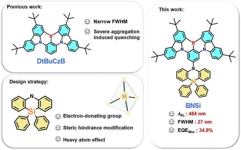
Thermally activated delayed fluorescence (TADF) emitters have garnered significant attention and increasingly widespread use in organic light-emitting diodes (OLEDs).1–4 Theoretically, TADF materials can achieve 100% internal quantum efficiency (IQE) without using precious metals, as they can harvest both singlet (S1) and triplet (T1) excitons owing to a small energy gap (ΔEST) between the S1 and T1 excited states, which can effectively promote the rate of the reverse intersystem crossing (RISC) process. By introducing spatially twisted electron donor (D) and acceptor (A) groups, the ΔEST value can be minimized, thereby separating the highest occupied molecular orbital (HOMO) and the lowest unoccupied molecular orbital (LUMO) of traditional TADF materials.5–10 However, TADF materials with conventional D–A type structures exhibit significant structural relaxation due to the spatial separation of charge transfer (CT) excited states, resulting in wide Stokes shifts and large full width at half maximum (FWHM). This broad band emission hinders the current pursuit of high color purity and makes meeting the National Television System Committee (NTSC) and BT.2020 ultra-high-definition display standards challenging.In 2016, Hatakeyama et al. proposed the concept of multi-resonance thermally activated delayed fluorescence (MR-TADF) molecules, which utilize the opposite resonance effects of nitrogen and boron atoms.11 By arranging the distribution of HOMO and LUMO at the atomic level, MR-TADF emitters based on a rigid polycyclic aromatic hydrocarbon framework can achieve both rapid radiative transitions and narrow band emissions.12–19 Recently, a promising strategy to achieving high-performance blue OLEDs has been through the use of MR-TADF emitters containing boron/nitrogen (B/N). Among these MR-TADF emitters, DtBuCzB stands out as a prominent candidate due to its remarkably simple molecular structure, which is conducive to cost-effective large-scale production.20 However, the relatively planar configuration of DtBuCzB can lead to significant π–π stacking interactions, resulting in aggregation-caused quenching (ACQ) effects. Therefore, DtBuCzB has a tendency to form excimers even at very low doping concentrations (≤1 wt%), leading to emission bands with markedly reduced energy and intensity. These excimers offer a vital pathway for exciton quenching, resulting in an increase in the full width at half maximum (FWHM) and subsequently deteriorating device performance.21–23
To address this problem, introducing steric hindrance into the DtBuCzB is being investigated to improve the performance. In 2021, Yang et al. compared the impact of methyl and phenyl-substituted pyridine donors on MR-TADF characteristics.24 By incorporating larger peripheral groups via phenyl pendant groups, the external quantum efficiency (EQE) can reach approximately 28%, effectively decreasing efficiency roll-off. Recently, Zhang et al. introduced 10H-spiro[acridine-9,2′-adamantane] (a-DMAc) in various connection modes at the periphery to achieve diverse conformation distributions, aiming to reduce ACQ effects at elevated concentrations.25 Even with a high doping ratio of 30%, the peak external quantum efficiency can still be maintained at 23.8%. While these substituents have demonstrated value, our objective is to introduce a novel substituent strategy that not only enhances steric hindrance but also improves the photophysical properties of the molecule.
In this study, we designed a blue TADF emitter BNSi by selecting a typical MR-TADF skeleton known as DtBuCzB, and 10,10-diphenyl-5,10-dihydro-dibenzo[b,e][1,4]azasiline (DPPASi) as a peripheral group substituted at the para-position of the boron atom (Fig. 1). DPPASi successfully weakened the electron-withdrawing ability of the boron atom as a weak and stable electron-donating group, allowing the spectrum to maintain a blue emission.26,27 The silicon atom also effectively enhanced the RISC process of the emitter as a heavy atom. More importantly, the DPPASi group, as a bulky substituent, has successfully weakened the π–π interactions between the DtBuCzB segment, thereby suppressing the aggregation-caused quenching (ACQ) effect at high concentrations. Consequently, this material exhibited excellent device performance: the maximum EQE (EQEmax) of the BNSi device reached 33.9% under 15 wt%, with an emission wavelength of 484 nm and an FWHM of 27 nm. Using tris (2-phenylpyridinato-C2, N) iridium(III) (FIrpic) as the sensitizer, the TADF-sensitized fluorescent (TSF) OLED device of BNSi achieved an EQEmax of 34.8%. This exploration is significant for the future development of efficient silicon-substituted narrow-spectrum blue emitters.
Results and discussion
Molecular design and synthesis
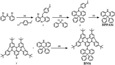
The synthetic scheme of the new blue-emitting material BNSi is illustrated in Scheme 1. The amino group in bis(2-bromophenylamine) was blocked by 4-methoxybenzyl to obtain intermediate 1. Cyclization was then carried out via nucleophilic substitution, and after a one-step deprotection to get DPPASi, the final product BNSi was obtained through Buchwald–Hartwig coupling. After column chromatography and recrystallization, the final products were further purified by temperature gradient sublimation at 360 °C under a high vacuum (<10−4 Pa) to obtain pure materials for characterization and OLED evaluation. The chemical structure was fully characterized by 1H-NMR and 13C-NMR, mass spectrometry (MALDI-TOF), and single-crystal X-ray diffraction analysis. Detailed synthesis procedures and characterization data are provided in the ESI.†Single crystal analysis and theoretical calculation
To characterize the impact of the DPPASi group on molecular conformation and stacking behavior, single crystals of BNSi were grown through gradual diffusion of ethanol in a dichloromethane solution. The molecular structure was determined by single-crystal X-ray diffraction (XRD) analysis. As shown in Fig. 2a and b, BNSi exhibits a rigid orthogonal structure in the single crystal, with a dihedral angle of 80.8° between the acridine plane and the DtBuCzB plane. The DPPASi group effectively reduces the overlap area of the luminescent fragments of the rigid planar structure and enables BNSi to present a J-aggregation stacking mode with an intermolecular distance of 3.52 Å (Fig. S1, ESI†).28–30 Additionally, the steric hindrance of peripheral modification groups tends to dominate the interaction force between DPPASi and the luminescent fragment (DtBuCzB), effectively decreasing the π–π interaction between luminescent planes.31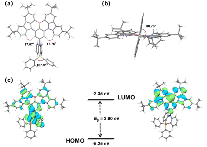 | ||
| Fig. 2 Front view (a) and top view (b) single-crystal structures of BNSi; HOMO and LUMO electron density distribution and energy levels of orbitals of BNSi (c). | ||
To further investigate the MR-TADF properties of the emitter, density functional theory (DFT) calculations of BNSi were performed at the B3LYP/6-31G(d,p) level for ground states (Fig. 2c).32–34 As expected, the LUMO remains distributed on the DtBuCzB segment, while the HOMO of BNSi extends to the DPPASi segment. The HOMO distribution of BNSi indicates that the DPPASi group, acting as a donor attached at the para position of the boron atom, weakens the electron-withdrawing ability of the boron atom, resulting in a shallower HOMO energy level for BNSi. Additionally, to investigate the properties of the emissive state of BNSi, the geometries of the S1 and the T1 of both conformers of BNSi and DtBuCzB have also been optimized with time-dependent DFT (TDDFT) at the B3LYP/6-31G(d,p) level (Fig. 3). The electron–hole analysis shows that both S1 and T1 states of BNSi possess significant π–π* transition characteristics.35 The SOC constants of the S1 and T1 states of the BNSi molecule were further calculated (Fig. 3), for comparison, the same calculations were performed on the DtBuCzB fragment (Fig. S2, ESI†). Results show that the SOC constants (S1|ĤSOC|T1 = 0.31 cm−1) of BNSi were significantly increased compared with the result of DtBuCzB (S1|ĤSOC|T1 = 0.05 cm−1), proving that the heavy atom effect of the silicon atom successfully enhances the spin–orbit coupling of the S1 and T1 states of the BNSi molecule, greatly promoting the RISC process of the molecule.36–39
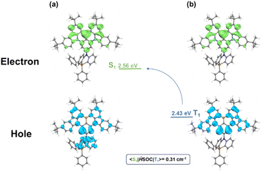 | ||
| Fig. 3 The analysis for the distribution of the hole and electron for the singlet excited states (a) and triplet excited state (b) of BNSi. | ||
Photophysical properties
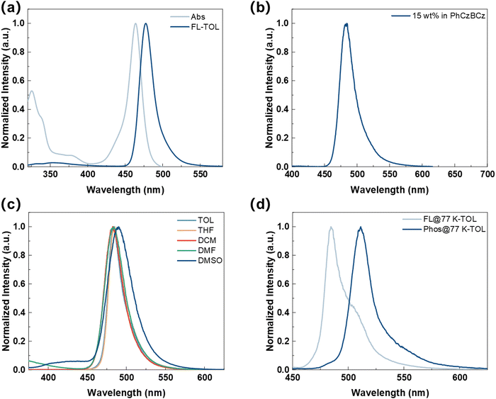
To systematically understand the underlying principles of peripheral DPPASi modification, we conducted a comprehensive study of the photophysical properties of BNSi (Fig. 4). The UV-vis absorption and photoluminescence (PL) spectra of BNSi in toluene solution are shown in Fig. 4a, with key data summarized in Table 1. The results were further compared with the corresponding parent molecule DtBuCzB (for detailed solution photophysical data, please refer to the ESI†). The absorption band below 400 nm in the emitter is attributed to the π–π* transitions of the conjugated structure.35 Due to the short-range intramolecular charge transfer (ICT) characteristics of its chromophore, the absorption spectrum of BNSi shows a maximum peak at 464 nm. The PL spectrum of BNSi also exhibits a narrow emission peak at 477 nm. The small Stokes shift of 13 nm indicates suppressed structural relaxation and low reorganization energy between the S0 and S1 states in the emitter, which also lead to a minimal FWHM of 22 nm. Compared with DtBuCzB, the small bandgap and blue-shifted PL spectrum of BNSi can be attributed to the inherent electron-donating properties of DPPASi. Furthermore, a change in solvent polarity from weak (toluene) to strong (dimethyl sulfoxide) causes a slight red shift and gradual broadening of the BNSi spectrum (Fig. 4c), indicating the presence of CT characteristics in the molecule's lowest excited state S1.40| Compound | λ Abs (nm) | λ PL (nm) | FWHMa (nm) | S1/T1b (eV) | ΔESTc (eV) | E g (eV) | HOMOe/LUMOf (eV) | T d (°C) |
|---|---|---|---|---|---|---|---|---|
| a Absorption and fluorescence peak wavelengths, FWHM, Stokes shift in toluene solutions at room temperature. b Estimated from the short-wavelength onset of the fluorescence/phosphorescence spectra at 77 K in frozen toluene. c ΔEST = ES − ET. d The optical bandgaps (Eg) calculated from the onset of the absorption spectra. e HOMO levels were determined from cyclic voltammetry measurements. f LUMO = HOMO + Eg. g Decomposition temperature corresponding to 5% weight loss from TGA measurements. | ||||||||
| BNSi | 464 | 477 | 22 | 2.56/2.43 | 0.13 | 2.9 | −5.25/−2.35 | 465 |
| DtBuCzB20 | 467 | 481 | 22 | 2.66/2.53 | 0.13 | 2.55 | −5.40/−2.85 | 445 |
Subsequently, we further studied the photophysical properties of BNSi by incorporating it into a 15% concentration 9H-carbazole, 3-(2-[3,9′-bi-9H-carbazol]-9-ylphenyl)-9-phenyl (PhCzBCz) film. BNSi exhibits blue light emission (λ = 484 nm, FWHM = 28 nm). Compared to the dilute solution in toluene, the spectrum shows a slight red shift and broadening due to the host–guest interaction of MR-TADF materials. Additionally, because the PhCzBCz film effectively restricts the intramolecular vibrational energy loss of BNSi, its PLQY increased from 85% in toluene solution to 99%. Based on the PLQY and the fitting transient PL decay curves, the dynamic rate constants of the excited state were calculated and summarized in Table S2 (ESI†). The prompt lifetime (τP) and delayed lifetime (τD) were derived to be 8.5 ns and 90 μs, respectively. The radiative transition rate constant (kr) of the singlet state for the BNSi-doped thin film was calculated to be 1.17 × 10⁷ s−1. More importantly, the RISC rate (kRISC) for BNSi was calculated to be 1.01 × 10⁵ s−1. Consistent with our supposition, BNSi exhibits high kRISC and PLQYs, and thus will enable OLED devices based on BNSi to have high EQE and narrow spectral emission under high doping ratios.
Thermal gravimetric analysis (TGA) was conducted in a nitrogen atmosphere to investigate the thermal stability of BNSi. The results, as shown in Fig. S4 (ESI†), indicate that BNSi has good stability, demonstrated by a high decomposition temperature (Td) of 465 °C (corresponding to 5% weight loss), which may be attributed to its rigid molecular structure and substantial molecular weight. Furthermore, cyclic voltammetry (CV) was employed to evaluate the electrochemical properties of BNSi, the analysis reveals reversible oxidation/reduction behavior for BNSi. The HOMO and LUMO energy levels of BNSi (Table 1) are calculated to be −5.25 and −2.35 eV, respectively, consistent with simulation results.
Electroluminescent performance and device optimization
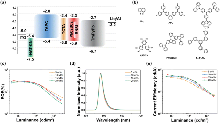
First, the electroluminescent performance of BNSi in vacuum-deposited devices was investigated. The device was fabricated with the structure of ITO/HAT-CN (10 nm)/TAPC (40 nm)/TCTA (10 nm)/PhCzBCz: x wt% emitter (20 nm)/TmPyPB (40 nm)/Liq (2 nm)/Al (80 nm). In this configuration, indium tin oxide (ITO) and aluminum (Al) served as the anode and cathode respectively. HAT-CN (1,4,5,8,9,11-hexaazatriphenylenehexacarbonitrile) and Liq acted as the hole injection layer and electron injection layer, respectively; TAPC (1,1-bis[(di-4-tolylamino)phenyl]cyclohexane) and TmPyPB (1,3,5-tri[(3-pyridyl)phen-3-yl]benzene) functioned as the hole transport layer and electron transport layer, respectively; TCTA and PhCzBCz were the exciton blocking layer and host material, respectively. Fig. 5a and b depict the electronic energy levels and chemical structures of the relevant compounds, and the electroluminescent performance parameters are shown in Fig. 5c–e and summarized in Table 2. The doped OLED exhibits a low turn-on voltage of approximately 3.0 V. Devices based on BNSi achieved blue emission at doping concentrations of 5 to 20 wt%, with an EQEmax of 33.9% at 15% doping concentration. Furthermore, the EQE remained around 30% at other high doping ratios (5, 10, 20 wt%). Notably, with increasing doping concentration, the EL emission peak redshifted slightly from 480 to 484 nm, with almost no broadening of the FWHM (26 to 27 nm). These trends suggest that connecting the DPPASi unit to the MR-TADF core effectively prevents dopant aggregation. In comparison, the OLED device based on DtBuCzB (15 wt%) with the same structure was fabricated, and the data are summarized in Fig. S6 and Table S5 (ESI†). Consistent with our predictions, analysis reveals that at the same high doping ratio (15 wt%), the DtBuCzB devices exhibit a 10 nm red shift in the EL peak and the FWHM has broadened to 36 nm. The comparison results demonstrate that the introduction of the DPPASi group effectively reduces the interaction of conjugated planes and suppresses the ACQ effect between the DtBuCzB segments.| Emitters | X (wt%) | V on (V) | FWHMb (nm) | λ EL (nm) | CEd (cd A−1) | EQEe (%) |
|---|---|---|---|---|---|---|
| a Onset voltages at the current density of 0.01 mA cm−2. b Full width at half maximum. c Electroluminescence peak wavelength. d Maximum current efficiency. e Maximum external quantum efficiency and values at 100 and 1000 cd m−2. | ||||||
| BNSi/PhCzBCz | 5 | 3.1 | 26 | 480 | 40.1 | 29.4/24.0/7.0 |
| 10 | 3.1 | 27 | 484 | 40.5 | 31.1/24.5/8.7 | |
| 15 | 3.1 | 27 | 484 | 51.3 | 33.9/23.6/6.5 | |
| 20 | 3.0 | 27 | 484 | 41.5 | 26.5/21.0/5.1 | |
| BNSi/PhCzBCz/FIrpic | 15 | 3.0 | 28 | 484 | 53.2 | 34.8/29.6/19.4 |
To further improve device efficiency, FIrpic was used as a sensitizer to assist exciton recycling at a doping rate of 15 wt% (Fig. S7, ESI† and Table 2). The sensitized OLED device based on BNSi maintained a narrow spectrum blue emission with an FWHM of 28 nm (λEL = 484 nm), achieved an EQEmax of 34.8%, and reduced efficiency roll-off to 44.2% through sensitization techniques.
Conclusions
In summary, we propose a strategy of attaching a DPPASi group to the MR framework to develop the blue MR-TADF emitter BNSi. In addition to inheriting the MR framework of DtBuCzB, this work introduced DPPASi, which contains a silicon atom, as a weak donor unit at the para-position of the boron atom. This modification allows BNSi to achieve narrow band emission at 480 nm with an FWHM of 26 nm approximately. Furthermore, the introduction of DPPASi as a bulky steric hindrance group effectively weakens the π–π interactions between the emitting planes, enabling OLED devices based on BNSi to achieve narrow band blue emission with high efficiency at high doping ratios. The EQEmax reached 34.8% when using FIrpic as the sensitizer. Our research highlights the potential role of large steric hindrance weak donor groups in MR-TADF emitters, which is crucial for designing blue MR-TADF emitters by leveraging the steric hindrance effect. We believe that our proposed design strategy will enrich the exploration of molecular design and high-performance MR-TADF emitters.Data availability
The authors confirm that the data supporting the findings of this study are available within the article [and/or] its ESI.†Conflicts of interest
There are no conflicts to declare.Acknowledgements
The authors acknowledge financial findings from the National Natural Science Foundation of China (No. 62375193, 22175124, and 62175171) and the Natural Science Foundation of Jiangsu Province of China (BK20220057). This work is also supported by Suzhou Key Laboratory of Functional Nano & Soft Materials, Collaborative Innovation Center of Suzhou Nano Science & Technology, the 111 Project, and Joint International Research Laboratory of Carbon-Based Functional Materials and Devices.Notes and references
- G. Hong, X. Gan, C. Leonhardt, Z. Zhang, J. Seibert, J. M. Busch and S. Brase, Adv. Mater., 2021, 33, 2005630 CrossRef CAS.
- S. Hirata, Y. Sakai, K. Masui, H. Tanaka, S. Y. Lee, H. Nomura, N. Nakamura, M. Yasumatsu, H. Nakanotani, Q. Zhang, K. Shizu, H. Miyazaki and C. Adachi, Nat. Mater., 2015, 14, 330 CrossRef CAS.
- H. Uoyama, K. Goushi, K. Shizu, H. Nomura and C. Adachi, Nature, 2012, 492, 234 CrossRef CAS.
- Y. L. Zhang, S. Y. Yang, Z. Q. Feng, Y. K. Qu, D. Y. Zhou, C. Zhong, L. S. Liao and Z. Q. Jiang, Sci. China: Chem., 2022, 65, 2219 CAS.
- Y. Tao, K. Yuan, T. Chen, P. Xu, H. Li, R. Chen, C. Zheng, L. Zhang and W. Huang, Adv. Mater., 2014, 26, 7931 CrossRef CAS.
- Q. Zhang, B. Li, S. Huang, H. Nomura, H. Tanaka and C. Adachi, Nat. Photonics, 2014, 8, 326 CrossRef CAS.
- X. Tang, L.-S. Cui, H.-C. Li, A. J. Gillett, F. Auras, Y.-K. Qu, C. Zhong, S. T. E. Jones, Z. Q. Jiang, R. H. Friend and L.-S. Liao, Nat. Mater., 2020, 19, 1332 CrossRef CAS.
- K. Goushi, K. Yoshida, K. Sato and C. Adachi, Nat. Photonics, 2012, 6, 253 CrossRef CAS.
- W. Yuan, M. Zhang, X. Zhang, X. Cao, N. Sun, S. Wan and Y. Tao, Dyes Pigm., 2018, 159, 151 CrossRef CAS.
- L. S. Cui, H. Nomura, Y. Geng, J. U. Kim, H. Nakanotani and C. Adachi, Angew. Chem., Int. Ed., 2017, 56, 1571 CrossRef CAS.
- T. Hatakeyama, K. Shiren, K. Nakajima, S. Nomura, S. Nakatsuka, K. Kinoshita, J. Ni, Y. Ono and T. Ikuta, Adv. Mater., 2016, 28, 2777 CrossRef CAS.
- C. Y. Chan, S. Madayanad Suresh, Y. T. Lee, Y. Tsuchiya, T. Matulaitis, D. Hall, A. M. Z. Slawin, S. Warriner, D. Beljonne, Y. Olivier, C. Adachi and E. Zysman-Colman, Chem. Commun., 2022, 58, 9377 RSC.
- S. Madayanad Suresh, D. Hall, D. Beljonne, Y. Olivier and E. Zysman-Colman, Adv. Funct. Mater., 2020, 30, 1908677 CrossRef CAS.
- J. M. Teng, Y. F. Wang and C. F. Chen, J. Mater. Chem. C, 2020, 8, 11340 RSC.
- H. J. Kim and T. Yasuda, Adv. Opt. Mater., 2022, 10, 2201714 CrossRef CAS.
- R. K. Konidena and K. R. Naveen, Adv. Photon. Res., 2022, 3, 2200201 CrossRef CAS.
- T. Hua, J. Miao, H. Xia, Z. Huang, X. Cao, N. Li and C. Yang, Adv. Funct. Mater., 2022, 32, 2201032 CrossRef CAS.
- Y. T. Lee, C. Y. Chan, M. Tanaka, M. Mamada, K. Goushi, X. Tang, Y. Tsuchiya, H. Nakanotani and C. Adachi, Adv. Opt. Mater., 2022, 10, 2200682 CrossRef CAS.
- S. Y. Yang, Q. S. Tian, X. J. Liao, Z. G. Wu, W. S. Shen, Y. J. Yu, Z. Q. Feng, Y. X. Zheng, Z. Q. Jiang and L. S. Liao, J. Mater. Chem. C, 2022, 10, 4393 RSC.
- Y. Xu, Z. Cheng, Z. Li, B. Liang, J. Wang, J. Wei, Z. Zhang and Y. Wang, Adv. Opt. Mater., 2020, 8, 1902142 CrossRef CAS.
- Z. Yang, G. X. Yang, S. Jiang, M. Li, W. Qiu, X. Peng, C. Shen, Y. Gan, K. Liu, D. Li and S. J. Su, Adv. Opt. Mater., 2024, 12, 2301711 CrossRef CAS.
- D. Li, M. Li, D. Liu, J. Yang, W. Li, H. Yang, H. Yuan, S. Jiang, X. Peng, G. X. Yang, W. Xie, W. Qiu, Y. Gan, K. Liu and S. J. Su, Adv. Opt. Mater., 2023, 11, 2301084 CrossRef CAS.
- Y. K. Qu, D. Y. Zhou, F. C. Kong, Q. Zheng, X. Tang, Y. H. Zhu, C. C. Huang, Z. Q. Feng, J. Fan, C. Adachi, L. S. Liao and Z. Q. Jiang, Angew. Chem., Int. Ed., 2022, 134, e202201886 CrossRef.
- P. Jiang, L. Zhan, X. Cao, X. Lv, S. Gong, Z. Chen, C. Zhou, Z. Huang, F. Ni, Y. Zou and C. Yang, Adv. Opt. Mater., 2021, 9, 2100825 CrossRef CAS.
- H. Wu, Y. Z. Shi, M. Y. Li, X. C. Fan, F. Huang, K. Wang, J. Yu and X. H. Zhang, Chem. Eng. J., 2024, 480, 147977 CrossRef CAS.
- K. Matsuo and T. Yasuda, Adv. Opt. Mater., 2022, 10, 2102568 CrossRef.
- S. J. Woo, Y. Kim, S. K. Kwon, Y. H. Kim and J. J. Kim, ACS Appl. Mater. Interfaces, 2019, 11, 7199 CrossRef CAS PubMed.
- M. Kasha, H. R. Rawls and M. A. El-Bayoumi, Pure Appl. Chem., 1965, 11, 371 CAS.
- T. Förster, Discuss. Faraday Soc., 1959, 27, 7 RSC.
- Z. Xie, B. Yang, Y. Ma and J. Shen, Chin. J. Polym. Sci., 2007, 25, 9 CrossRef CAS.
- Y. J. Yu, Z. Q. Feng, X. Y. Meng, L. Chen, F. M. Liu, S. Y. Yang, D. Y. Zhou, L. S. Liao and Z. Q. Jiang, Angew. Chem., Int. Ed., 2023, 62, e202310047 CrossRef CAS PubMed.
- A. Dreuw and M. Head-Gordon, Chem. Rev., 2005, 105, 4009 CrossRef CAS PubMed.
- P. J. Stephens, F. J. Devlin, C. F. Chabalowski and M. J. Frisch, J. Phys. Chem., 2002, 98, 11623 CrossRef.
- E. Runge and E. K. U. Gross, Phys. Rev. Lett., 1984, 52, 997 CrossRef CAS.
- H. Lee, R. Braveenth and S. Muruganantham, Nat. Commun., 2023, 14, 419 CrossRef CAS PubMed.
- M. A. El-Sayed, Acc. Chem. Res., 1968, 1, 8 CrossRef CAS.
- M. A. El-Sayed, J. Chem. Phys., 1963, 38, 2834 CrossRef CAS.
- M. K. Etherington, J. Gibson, H. F. Higginbotham, T. J. Penfold and A. P. Monkman, Nat. Commun., 2016, 7, 13680 CrossRef CAS.
- J. Gibson, A. P. Monkman and T. J. Penfold, ChemPhysChem, 2016, 17, 2956 CrossRef CAS.
- D. Karthik, Y. H. Jung, H. Lee, S. Hwang, B. M. Seo, J. Y. Kim, C. W. Han and J. H. Kwon, Adv. Mater., 2021, 33, 2007724 CrossRef CAS.
Footnotes |
| † Electronic supplementary information (ESI) available. CCDC 2369645. For ESI and crystallographic data in CIF or other electronic format see DOI: https://doi.org/10.1039/d4tc04002c |
| ‡ These authors contributed equally to this work. |
| This journal is © The Royal Society of Chemistry 2024 |

