 Open Access Article
Creative Commons Attribution 3.0 Unported Licence
Dry reforming of steelworks off-gases in a pilot plant integrated into a steel mill: influence of operating parameters†
Philipp
Blanck
 a,
Gilles
Kass
b,
Klaus Peter
Kinzel
b and
Olaf
Deutschmann
 *a
*a
aInstitute for Chemical Technology and Polymer Chemistry, Karlsruhe Institute of Technology (KIT), 76131 Karlsruhe, Germany. E-mail: deutschmann@kit.edu
bPaul Wurth S.A., L-1122 Luxembourg, Luxembourg
First published on 26th October 2023
Abstract
A novel process is applied in a pilot plant integrated within a steel mill in Saarland, Germany, in which the greenhouse gases CO2 and CH4 are converted into synthesis gas, a mixture of H2 and CO, by homogeneous dry reforming. The process is based on heating a gas mixture of coke oven gas (COG) and blast furnace gas (BFG) to high temperatures in a regenerative heat exchanger, similar to the existing hot blast stoves used to heat the hot blast blown into the blast furnace. The resulting synthesis gas can be injected into the blast furnace at the level of the shaft and/or tuyere, reducing coke consumption in iron production, potentially leading to a reduction in global CO2 emissions of about 0.5%. After commissioning, the cyclic operating pilot plant was used to study a wide variation of operating parameters. At a maximum local peak temperature of over 1721 K during the synthesis gas production phase, an average conversion of about 97% for CH4 and over 94% for CO2 was achieved, which is close to the thermodynamic equilibrium of over 99% and about 98%, respectively. The scale-up process is accomplished by modeling and numerical simulation. The measured data obtained from the pilot plant agree well with the numerical simulations using a detailed elementary-step reaction mechanism.
Introduction
The industrial sector responsible for the largest carbon dioxide emissions is the iron and steel industry, accounting for about 31% of all industrial and 8% of the total global emissions.1,2 In the steelmaking industry, two main processes can be distinguished: primary and secondary steel production. Secondary steelmaking is the smelting of scrap and is limited by the amount of steel that can be recycled. Primary steelmaking is the most widespread and today there are two principal commercial processes of primary steelmaking. The first process is the blast furnace (BF) with a subsequent blast oxygen furnace (BOF), also called converter. The second process is the direct reduction of iron ore (DRI) in a shaft furnace with an additional electric arc furnace (EAF) for melting and cleaning the directly reduced iron.In direct reduction, the iron ore is brought into contact with a reducing gas containing carbon monoxide and hydrogen, resulting in directly reduced iron, also called sponge iron, with an iron content of 85–95%.3 Recent technological developments envisage iron reduction only in the presence of hydrogen obtained from renewable technologies.4 The overall share of the DRI/EAF route is between 5% and 6% worldwide, but it is growing.5,6 However, due to the high investment costs for DRI plants, retrofitting existing steel mills is a promising transitional solution to reduce CO2 emissions in this highly emitting industrial sector. Of these two process routes in primary steelmaking, the BF/BOF route currently dominates the iron and steel industry, accounting for over 70% of global steel production.4,6,7 In this process, the reduction of iron ore causes a very high specific energy consumption, which in practice accounts for more than half of the energy consumed in steel works. For many decades this basic chemical process was accomplished exclusively in the blast furnace, for which coke was available as the sole energy source. This coke is produced from coal in the coke oven by pyrolysis. The global chemical reactions of coke with oxygen to provide energy (eqn (1)), the Boudouard reaction to produce the reducing agent (eqn (2)) and the subsequent reaction of carbon monoxide to reduce iron ore (eqn (3)) in the blast furnace proceed as follows:
 | (1) |
 | (2) |
 | (3) |
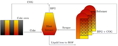
The process is based on heating a gas mixture of coke oven gas (COG) and blast furnace gas (BFG) to high temperatures in a regenerative heat exchanger. Both gases vary in their composition over time due to natural fluctuations within the steel mill. Table 1 shows typical ranges for these gases that were used in the pilot plant. In addition, these gases contain impurities such as sulfur compounds and suspended particles.
| Feed name | COG [vol%] | BFG [vol%] |
|---|---|---|
| CO | 7.7–8.8 | 22.1–25.7 |
| O2 | 0.7–1.2 | — |
| CO2 | 1.9–2.9 | 19.9–24.4 |
| CH4 | 18.3–20.6 | — |
| H2 | 53.1–59.8 | 3.7–6.9 |
| H2O | 0.1–0.5 | 2.0–3.7 |
| N2 | 6.4–11.7 | 39.3–52.3 |
| Cx>1Hy | 2.2–2.8 | — |
In eqn (4), the target endothermic chemical reaction of dry reforming (DR) is given; carbon dioxide from the BFG is used to treat hydrocarbons (here mainly CH4) from the COG to produce syngas.
 | (4) |
Due to the highly endothermic nature of dry reforming, energy is required in the form of heat. This large amount of required heat energy can be provided by blast furnace gas. Since BFG makes up the largest share of all metallurgical waste gases, it can be used in this process both thermally to provide the required thermal energy for the dry reforming reaction and chemically as a reactant.
In addition to the dry reforming reaction, a variety of endothermic and exothermic side reactions take place (eqn (5)–(9)):
 | (5) |
 | (6) |
 | (7) |
 | (8) |
 | (9) |
Experimental set-up and operating conditions
The heart of the test plant is a horizontal, refractory-lined channel that can be divided into four main sections, as shown in Scheme 2. The checker chamber, highlighted in yellow, is the largest part and can be divided into 20 sections, which are all lined with the so-called checker bricks. The checker bricks are alumina-based refractory bricks with small channels through which the gas flows. These checker bricks are also an important component of the cowpers, which store the thermal energy to provide the hot blast for the blast furnace process. The hot blast is obtained by heating fresh air over the heat storage bricks in the cowpers, which are previously heated by burning enriched blast furnace gas. The hot blast is then fed into the blast furnace at a temperature of around 1573 K.In the pilot plant, this heat retaining lining is actively heated by burner exhaust gases during the heating phase and transfers the stored thermal energy to the incoming gas stream, which is converted into synthesis gas in the production phase. At the outer end of the burner chamber, the burner is installed in which the waste gas for heating the checker chamber is generated. In the pilot plant, this heat is generated by burning coke oven gas with air, which distinguishes it from an integrated industrial plant. The exhaust gas evacuation system is installed at the other end of the checker chamber. Before the exhaust gas is released into the atmosphere via a stack, it is cooled with air. The syngas main is the part of the duct that discharges the produced syngas into the flare stack and is connected to the system via a tee. The syngas is cooled with nitrogen before being burned in the flare and released into the atmosphere. An important function for maintaining the cyclic operation of the pilot plant, is that the burner chamber can be separated from the rest of the set-up by two water-cooled slide valves. The separation prevents that the synthesis gas generated in the production phase enters the burner chamber.
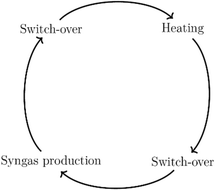
The pilot plant is designed to operate fully automatically and continuously. The operating mode is cyclic and is divided into four phases, which are illustrated in Scheme 3. The pilot plant is automated to a degree that these cycles are running completely autonomously. The plant is designed to meet the following characteristics: a syngas flow rate of between 100 N m3 h−1 to 200 N m3 h−1, a maximal operating pressure up to 6 barg and a maximum operating temperature of about 1823 K.
The first phase is the heating phase, in which the checker chamber is heated by burning coke oven gas with air in the burner chamber, highlighted red in Scheme 2. The hot flue gas flows through the holes in the checker bricks and heats the refractory lining to the preset operating temperature. The checker bricks store the energy during the heating phase. In addition, potential soot deposits are burned and discharged with the gas stream. The formation of these deposits occurs through several reactions that are favored under current conditions. The most important reactions, are Boudouard (eqn (2)), CO and CO2 reduction (eqn (7) and (8)), and CH4 cracking (eqn (9)). This burnout is important to ensure proper heat and mass transfer through the checker bricks. At the end of the checker chamber, in the exhaust gas evacuation (marked brown), the flue gas is released. Since the temperature of the flue gas can reach 1273 K or more at the outlet during the heating phase, an ambient air cooling system is connected upstream of the fan. Air from the atmosphere is sucked in by the negative pressure upstream of the fan. At the very end, the cooled gas is discharged via a stack downstream of the fan.
The switch-over phases ensure safe transitions between the heating and syngas production phase. Inerting with nitrogen takes place in order to avoid any contact between the oxygen-rich burner waste gas and the flammable synthesis gas.
After heating-up to preset temperature, the test plant is ready to start the syngas production. After the gas mixture is introduced, it is gradually heated by heat transfer (convection and radiation) from the hot checker bricks to the gas mixture. When the mixture reaches a sufficient temperature level, chemical reactions occur. The energy consumed to heat the incoming gas mixture and the energy required for the endothermic chemical reaction result in a progressive decrease of the temperature of the checker bricks. When the temperature is no longer sufficient for chemical conversion, the production phase is stopped and a new heating phase is initiated after an in-between switch-over phase.
Model approach
The DETCHEM software package was used as a simulation tool in this work. It performs kinetic calculations and is specifically designed for the modelling and simulation of reactive flows, including surface reactions, particular for heterogeneous systems, including the coupling of a variety of reactor models with the consideration of detailed chemical kinetic models.12 Elementary step-based reaction mechanisms or global reaction kinetics can be used for these calculations. To simulate the dry reforming process in the novel plant reactor, the DETCHEMCHANNEL code is used, modelling a two-dimensional gas flow through the cylindrical channel. It enables the consideration of both surface and gas-phase reactions.13A very suitable chemical reaction mechanism describing the oxidation and pyrolysis of methane is the PolyMech polygeneration mechanism, which is used without modification in this work for all simulations of the dry reforming process. PolyMech consists of 558 elementary reactions between 83 gaseous species and was also developed to describe extremely rich reaction conditions for polygeneration processes.14 The mechanism includes not only reactions for the main products, but also for a number of species such as C2H6, C2H4, C2H2 and C6H6, which are used as indicators of the tendency to form carbon.15 Their inclusion is of great interest, as the possible formation of carbonaceous deposits can lead to technical problems in industrial plants. PolyMech contains three sub-mechanisms. The mechanism includes the reaction kinetics of methane provided by Hidaka et al.,16 the reaction kinetics for the combustion of dimethylether (DME) by Zhao et al.,17 and the oxidation kinetics for the C1–C4 species by Heghes.18 The mechanism PolyMech was validated against experimental data before and performed well.14,19
The CaRMeN (catalytic reaction mechanism network) software, a tool that supports the comparison of modelled and experimental results, was used to evaluate the reaction mechanism with the associated rate expressions and the numerical simulations of the reactor including the pilot plant specific parameters. CaRMeN works as an automation and graphical representation tool between simulation and measurement points and acts as an interface between user and the DETCHEM program package.20,21
Results and discussion
During commissioning and for investigation purpose, many cycles of syngas generation were evaluated, and simulations were performed using the measured composition of the incoming gas mixture. The composition of the incoming gas mixture and the synthesis gas produced is measured with a gas analyzer connected to two sampling ports on the reforming channel. A total of eight species can be detected: H2, O2, CO, CO2, H2O, CH4, C2H4 and C2H6. The temperature profile is measured with 19 temperature sensors along the reaction channel (highlighted in yellow in Scheme 2) in each section. An exemplary course of temperatures during cyclic operation is shown in Fig. 1.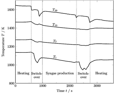 | ||
| Fig. 1 Temperature development over time in cyclic operation for 4 chosen temperature sensors along the reforming channel. | ||
For graphical illustration of the developing temperature profiles, the temperature in the first section T1, two temperatures in the middle of the reformer T7 and T13 and the last temperature of the reactor chamber T19 were chosen. After heating up to a preset operating value, the first switch-over phase takes place including inertization with nitrogen. The cold nitrogen causes a drop in temperature. After inertization, the temperatures rise again due to the heat stored in the bricks and synthesis gas production begins. In the production phase, there is continuous cooling due to the heating of the gas mixture, losses due to the endothermic reaction and also convection. The most significant temperature decrease during synthesis gas generation is observed in the first section, T1, caused by the heating of the cold inserted gas mixture, and in the last section, T19, where the maximum conversion occurs. When the conversion is no longer sufficient, a second inertization takes place and heating starts again. The temperature sensors in the middle of the channel show less variations during inertization because the nitrogen upstream is already heated before reaching these sensors. The last temperature sensor T19 is strongly influenced by the colder, less or not actively heated syngas channel. After the production phase, the pressure in the duct is released via the flare and inertization starts at low pressure. The significant temperature drop of T19 can be explained by a backflow of cold gas from the syngas main towards the checker chamber at low pressure level.
As shown in Fig. 1, the temperature profile changes not only between the different phases of each cycle, but also during synthesis gas generation. An example of an evolving temperature profile from the end of the heating phase to the end of a production cycle is given in Fig. 2, including temperatures in the syngas main (right side of thin dotted line in Fig. 2).
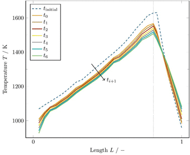 | ||
| Fig. 2 Measured temperature profiles in a production phase of about 25 minutes. The time discretization (ti − ti+1) used is set to 250 s. | ||
The time-dependent temperature profile along the channel is a function of the gas flow rate and the gas composition as well as the initial temperature of the checker bricks. The first temperature profile tinitial is measured when the heating phase ends and the switch-over phase begins. In this phase, inertization with nitrogen takes place, which has a great influence on the cooling of the refractory material. The temperature profile t0 is measured when the mixed gas line is opened and the gas mixture is introduced in the checker chamber.
The following 6 profiles, t1–t6, reveal the development of the temperature every 250 s. The CH4 conversion rate at t0 was calculated to be 82.7% decreasing to 66.4% at t6. The maximum temperature of the profile at the end of the checker chamber drops from 1561 K (t0) to 1508 K (t6) within 25 min. This clearly reveals the strong dependence of the conversion rate on the temperature profile. Therefore, the temperature profiles of each simulation must be re-implemented at appropriate time intervals to consider the dynamic operating conditions in the kinetic calculations.
The part of the channel where the checker bricks are located (part up to peak temperature in Fig. 2), the temperature drops continuously during synthesis gas production. In the section where the syngas is released (after the thin gray dotted line in Fig. 2) and which is not actively heated during the heating phase, the temperature increases due to the hot synthesis gas flowing to the flare. Four hutches can be distinguished in the evolving temperature profiles, located in the 3rd, 8th, 13th, and 18th sections of the checker chamber. The insulation in these sections is made of a specific refractory material, indicating a lower conductivity of the materials used in the area of the hutches. The improved insulation in these 4 sections can also be confirmed by the shell temperature of the reactor, which is about 10–12 K lower compared to the other sections, which indicates reduced heat loss through convection to the atmosphere.
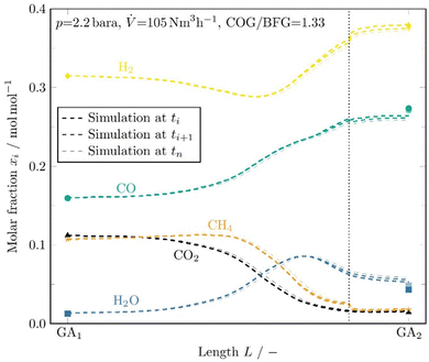
An example evaluation of the data from the gas analysis, inlet and outlet measurements (symbols), and comparison with the kinetic simulation (dashed lines) is shown in Fig. 3. Due to the decreasing temperature profile during synthesis gas production, a suitable time discretization had to be selected in each case because only one profile per simulation can be included in the code. Since this profile is highly time dependent over the syngas production, appropriate time steps must be created with individual simulations for each temperature profile respectively. This allows the evolution of the syngas composition over time to be observed.
In the evaluation shown in Fig. 3, a discretization of 3 time intervals was chosen, resulting in 3 slightly different simulation and gas analysis results. The thick dashed line is the first interval, the thinnest dashed line is the last. Two simulations are performed for each time interval. The first one up to the end of the checker chamber and the second for the syngas main to the sampling point on which the gas analyzer is connected. In the second simulation, a different geometry and thus gas velocity must be implemented in the model because of the missing checker bricks in the syngas main.
In the illustrated example cycle evaluation, a volumetric flow rate of 105 N m3 h−1 was set at a pressure of about 2.2 bara and a COG/BFG ratio of 1.33. The main reforming takes place between the middle section, where the gas mixture reaches sufficiently high temperatures, and the end of the checker chamber, where the highest temperatures prevail. After the dotted vertical line, a kink can be seen, especially for H2 and CH4. This behaviour is caused by the drop in gas velocity and the related increase in residence time in the first part of the syngas duct, where high temperatures are still measured.
Fig. 4 shows the pressure dependence of the conversion rate evolution for a COG/BFG ratio of 1.5, close to a hydrocarbon to oxidant ratio of 1. It is important to note that for a fixed volume flow of 100 N m3 h−1, as in this case, the velocity decreases and thus the residence time increases as the pressure is raised. Therefore, different residence times must automatically be considered when comparing the pressures. From Fig. 4, a clear pressure and thus residence time dependence of the conversion can be seen, whereby the residence time has a greater influence and pushes the reaction towards thermodynamic equilibrium. At high temperatures, residence time does not affect the conversion of CH4 and CO2 as much as in the lower temperature range. Especially in the temperature range between 1000 K and 1400 K, higher pressures and thus longer residence times shift the conversion of the main species towards their thermodynamic equilibrium. For temperatures between 1000 K to around 1350 K, the fraction of CH4 is predicted to increase and only at a temperature above 1350 K conversion of CH4 occurs. The conversion of H2O starts at temperatures above 1550 K and increases at higher pressures and thus longer residence times.
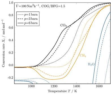 | ||
| Fig. 4 Simulated conversion rates as function of temperature at three different pressure levels predicted by DETCHEMCHANNEL. | ||
The CH4 conversion rate determined from numerous individual cycles is shown in Fig. 5 and compared with the maximum average temperature Tmax reached inside the reforming unit during a syngas production phase. Tmax is the average peak value of a temperature profile during syngas production.
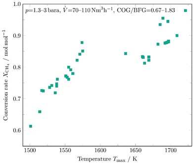 | ||
| Fig. 5 Conversion rate of CH4 of several syngas production phases as a function of the maximum average temperature in the reforming channel. | ||
The operating conditions in the evaluated cycles varied in the following ranges: pressure p = 1.3–3 bara, volumetric flow rate ![[V with combining dot above]](https://www.rsc.org/images/entities/i_char_0056_0307.gif) = 70–110 N m3 h−1, and a COG/BFG ratio of 0.67 to 1.83. The maximum temperature Tmax was always recorded in the last segments of the checker chamber. For technical reasons, the second sampling point of the gas analyser, where the composition of the synthesis gas produced is measured, was relocated during the measurements at high temperatures above 1600 K. Therefore, part of the further conversion in the hot syngas duct could not be further factored in. A dependence of the conversion rate on the maximum temperature reached is clearly evident and was expected before. It can also be seen that the methane conversion rates agree well with the kinetic model predictions, as shown in Fig. 4.
= 70–110 N m3 h−1, and a COG/BFG ratio of 0.67 to 1.83. The maximum temperature Tmax was always recorded in the last segments of the checker chamber. For technical reasons, the second sampling point of the gas analyser, where the composition of the synthesis gas produced is measured, was relocated during the measurements at high temperatures above 1600 K. Therefore, part of the further conversion in the hot syngas duct could not be further factored in. A dependence of the conversion rate on the maximum temperature reached is clearly evident and was expected before. It can also be seen that the methane conversion rates agree well with the kinetic model predictions, as shown in Fig. 4.
The dry reforming process has a high potential for soot formation due to the side reactions described above. The formation of soot was also observed in the previous laboratory tests by Angeli et al. especially in the cold parts of the reactor.11 However, this did not lead to problems in operation even with long test periods, and moreover, high temperatures were shown to suppress coke formation.11 For the performance of an industrial plant, operating conditions have been determined allowing to avoid operational problems in long periods of operation. Factors such as temperature and stoichiometric ratio have the main impact on these side reactions and suitable parameters could be obtained. The main side reactions that can lead to these undesirable deposits at low temperatures due to their exothermic nature are the Boudouard reaction (eqn (2)) and the hydrogenation of carbon monoxide (eqn (7)) and carbon dioxide (eqn (8)). Conversely, the decomposition of methane (eqn (9)) is endothermic and leads to increased soot formation as the temperature rises. The C2H4, C2H2 and C6H6 species can be considered as indicators of coke deposition.22 These coke precursors can be used to indicate the tendency to deposit carbon through surface reactions by prior condensation of small hydrocarbons to larger structures in the gas phase.15
Fig. 6 shows the evolution of the coke precursors simulated with DETCHEMCHANNEL for a wide range of continuous wall temperatures in the reaction tube. Three different gas ratios are chosen and the inlet gas flow is set to 100 N m3 h−1 at a pressure of 3 bara.
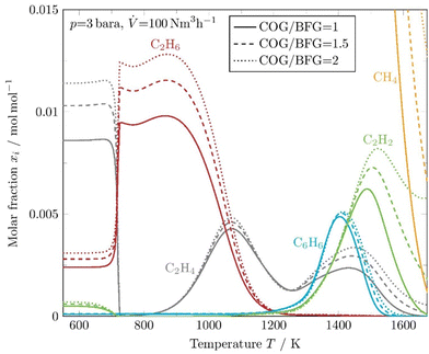 | ||
| Fig. 6 Kinetic simulation of coke precursors and methane at constant reactor wall temperatures for 3 different COG/BFG ratios. | ||
A temperature of about 700 K is required until the initial concentrations of C2H4 and C2H2 are shifted to a peak of C2H6. Methyl radicals ([CH3]˙) are mostly formed by H-abstraction from methane and rapidly recombine to form ethane (C2H6), which initiates a series of H-abstraction reactions to form stable species such as ethylene (C2H4) and acetylene (C2H2). When the temperature rises above 800 K, the concentration of C2H4 increases again and C2H6 decreases. Furthermore, it is apparent that the overall formation of coke precursors decreases as the initial concentration of higher hydrocarbons in the input stream decreases. Thus, the formation of carbonaceous deposits due to the Boudouard balance can be minimized if the process is operated with an excess of blast furnace gas. At a temperature of about 1200 K, the molar fraction of carbon precursors reaches a minimum. Carbon deposits are also expected at the regions where the temperature goes below 750 K due to the exothermic CO and CO2 reduction, and near the peak values of C2H4, C2H2, and C6H6.
Fig. 7 additionally shows the pressure and thus especially the residence time dependence of the development of the coke precursors for a fixed COG/BFG ratio of 1.5. It can be seen that the coke precursors occur in a higher molar fraction at high pressures and thus longer residence times, which was observed previously in thermodynamic equilibrium simulations. In particular, C2H2 stands out with a peak concentration of more than 2% at a temperature of about 1600 K and a pressure of 6 bara.
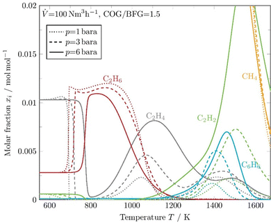 | ||
| Fig. 7 Kinetic simulation of coke precursors and methane at constant reactor wall temperatures at 3 different pressure levels. | ||
Coke formation was also observed in the pilot plant, but suitable parameters were found to avoid disturbances in operation. Since the plant is operated in a cyclic mode, the deposits are successfully burned off after each cycle, which will also be the mode of operation of a future industrial plant.
Conclusions
The integrated dry reforming process shows promising results and the possibility of reducing coke consumption by utilization of steel mill off-gases. Average conversions of 97% for CH4 and over 94% for CO2 were achieved at a maximum local peak temperature of over 1721 K during the synthesis gas production phase. The retrofitting of existing steel plants with an integrated dry reforming process offers the opportunity to cut greenhouse gas emissions in the steel industry, with a potential reduction in global CO2 emissions of about 0.5%.23 The adapted kinetic model shows reliable results for the dry reforming process. Based on the validation of the developed model, simulations can be performed to predict different scenarios with a variation of the operating parameters. Another important aspect of such a model is the possibility to change geometrical or operational parameters, which allows upscaling of the process and adaptation to different conditions.Conflicts of interest
The authors declare no conflict of interest.Acknowledgements
We acknowledge the very useful support by omegadot software & consulting GmbH for providing the software tools DETCHEM and CaRMeN.References
- M. Bui, C. S. Adjiman, A. Bardow, E. J. Anthony, A. Boston and S. Brown, et al., Carbon capture and storage (CCS): the way forward, Energy Environ. Sci., 2018, 11(5), 1062–1176 RSC.
- V. Vogl, M. Åhman and L. J. Nilsson, The making of green steel in the EU: a policy evaluation for the early commercialization phase, Clim. Policy, 2021, 21(1), 78–92 CrossRef.
- G. J. Lötter, A. A. van Niekerk and G. Farmer, Pig Iron Production (Post Blast Furnace Era), SSRN J., 2021 Search PubMed.
- N. McQueen, C. M. Woodall, P. Psarras and J. Wilcox, CCS in the Iron and Steel Industry, in Carbon Capture and Storage (Energy and Environment Series), ed. M. Bui and N. Mac Dowell, Royal Society of Chemistry, Cambridge, 2019, ch. 11 pp. 353–91 Search PubMed.
- A. Carpenter, CO2 abatement in the iron and steel industry, CCC193, IEA Clean Coal Centre, Londres, 2012 Search PubMed.
- Z. Fan and S. J. Friedmann, Low-carbon production of iron and steel: Technology options, economic assessment, and policy, Joule, 2021, 5(4), 829–862 CrossRef CAS.
- V. Shatokha, Environmental Sustainability of the Iron and Steel Industry: Towards Reaching the Climate Goals, Eur. J. Sustain. Dev., 2016, 5(4), 289–300 Search PubMed.
- CASTAGNOLA C, Via Franco Solimano 27/4, 16030 Sori (GE) (IT). MICHELETTI, Lorenzo, Via Campo alla capamna 216A, 57022 Castagneto Carducci (Livorno)(IT)., inventors. Method for operating a metallurgical furnace. PTC/EP2020/063342.
- KINZEL Klaus Peter – 5222 Sandweiler (Luxembourg), Anand Kumar-2611 Luxembourg (Luxembourg), inventor. Method for Producing a Synthesis Gas, in particular for use in Blast Furnace Operation. LU100453.
- Y. Yang, K. Raipala and L. Holappa, Ironmaking, Treatise on Process Metallurgy, Elsevier, 2014, pp. 2–88 Search PubMed.
- S. D. Angeli, S. Gossler, S. Lichtenberg, G. Kass, A. K. Agrawal and M. Valerius, et al., Reduction of CO2 Emission from Off-Gases of Steel Industry by Dry Reforming of Methane, Angew. Chem., Int. Ed., 2021, 60(21), 11852–11857 CrossRef CAS PubMed.
- O. Deutschmann, S. Tischer, S. Kleditzsch, V. Janardhanan, C. Correa and D. Chatterjee, et al., DETCHEM, 2020, Available from: URL: https://www.detchem.com Search PubMed.
- D. Chan, S. Tischer, J. Heck, C. Diehm and O. Deutschmann, Correlation between catalytic activity and catalytic surface area of a Pt/Al2O3 DOC: An experimental and microkinetic modeling study, Appl. Catal., B, 2014, 156–157, 153–165 CrossRef CAS.
- S. Porras, D. Kaczmarek, J. Herzler, S. Drost, M. Werler and T. Kasper, et al., An experimental and modeling study on the reactivity of extremely fuel-rich methane/dimethyl ether mixtures, Combust. Flame, 2020, 212, 107–122 CrossRef CAS.
- L. C. S. Kahle, T. Roussière, L. Maier, K. Herrera Delgado, G. Wasserschaff and S. A. Schunk, et al., Methane Dry Reforming at High Temperature and Elevated Pressure: Impact of Gas-Phase Reactions, Ind. Eng. Chem. Res., 2013, 52(34), 11920–11930 CrossRef CAS.
- Y. Hidaka, Shock-tube and modeling study of methane pyrolysis and oxidation, Combust. Flame, 1999, 118(3), 340–358 CrossRef CAS.
- Z. Zhao, M. Chaos, A. Kazakov and F. L. Dryer, Thermal decomposition reaction and a comprehensive kinetic model of dimethyl ether, Int. J. Chem. Kinet., 2008, 40(1), 1–18 CrossRef CAS.
- C. I. Heghes, C1–C4 Hydrocarbon Oxidation Mechanism [Dissertation], Rupertus Carola University of Heidelberg, Heidelberg, 2006 Search PubMed.
- S. C. Porras Seyler, Entwicklung von Reaktionsmechanismen für Systeme bei der Polygeneration, 2021 Search PubMed.
- H. Gossler, L. Maier, S. Angeli, S. Tischer and O. Deutschmann, CaRMeN: a tool for analysing and deriving kinetics in the real world, Phys. Chem. Chem. Phys., 2018, 20(16), 10857–10876 RSC.
- H. Gossler, L. Maier, S. Angeli, S. Tischer and O. Deutschmann, CaRMeN: An Improved Computer-Aided Method for Developing Catalytic Reaction Mechanisms, Catalysts, 2019, 9(3), 227 CrossRef.
- Soot Formation in Combustion: Mechanisms and Models, in Springer Series in Chemical Physics, ed. H. Bockhorn, Springer Berlin Heidelberg, Berlin, Heidelberg, 1994, vol 59 Search PubMed.
- Paul Wurth and the steel partners Dillinger and Saarstahl join forces on development of dry reforming technology; 2021 [cited 2023 Feb 2]. Available from: URL: https://www.paulwurth.com/en/paul-wurth-and-the-steel-partners-dillinger-and-saarstahl-join-forces-on-development-of-dry-reforming-technology/.
Footnote |
| † Electronic supplementary information (ESI) available. See DOI: https://doi.org/10.1039/d3ya00227f |
| This journal is © The Royal Society of Chemistry 2024 |

