 Open Access Article
Three-dimensional N, P, and O tri-doped porous carbon for multifunctional electrocatalytic reactions†
Lulu
Chen
a,
Yanan
Zhang
a,
Zhihui
Liu
b,
Liqiang
Hou
*a and
Xien
Liu
 *a
*a
aCollege of Chemical Engineering, Qingdao University of Science and Technology, Qingdao 266042, China. E-mail: houliqiang@qust.edu.cn; liuxien@qust.edu.cn
bLanzhou Petrochemical Research Center, Petrochemical Research Institute, PetroChina, Lanzhou 730060, China
First published on 4th December 2023
Abstract
With the gradual development of renewable energy technologies, developing metal-free carbon materials has attracted more attention as a new category of multifunctional electrocatalysts. Along with the deepening of the comprehension of the electrocatalytic nature, the electrocatalytic performance of carbon catalysts could be greatly regulated by embellishing with foreign atoms and pores. Herein, we synthesized a three dimensional N, P, O co-doped carbon framework (3D-NPOC) by using a simple annealing treatment with tannic acid as a precursor. Benefitting from the electronic structure optimization effect of foreign atoms and accelerated electrolyte transfer and gas diffusion derived from the interconnected 3D porous nanostructures, the obtained 3D-NPOC showed a relatively high ORR half-wave potential that is on a par with those of commercial Pt/C, delivered a comparable OER performance to IrO2, especially under high current densities, and also showcased comparatively good HER properties. More importantly, the obtained catalyst-based zinc–air batteries exhibited a comparable performance to Pt/C‖IrO2-based batteries.
1. Introduction
The gradually increasing non-renewable energy consumption will inevitably lead to global energy challenges and air pollution problems. To date, the great development of green renewable energy technologies, including fuel cells, rechargeable metal–air batteries, and water electrolyzes, has become a key strategy in energy development planning.1–4 However, the energy efficiency and practical application of these techniques are greatly limited by several important electrocatalytic reactions, such as the hydrogen evolution (HER), oxygen evolution reaction (OER), and oxidation–reduction reaction (ORR).5–8 In recent years, the widely accepted benchmark catalysts for these key reactions include Pt/C, RuO2, and IrO2. Nevertheless, their disadvantages, including exorbitant prices, low reserves, etc., significantly limit their large-scale application.9–12 Beyond that, such benchmark catalysts can’t catalyze various reactions alone, which would inevitably increase the overall cost of renewable energy equipment.13–15 Therefore, it is essential to develop effective multifunctional electrocatalysts with low cost that can greatly improve the kinetics of the reactions described above.As such, great efforts have been made to develop low-cost multifunctional catalysts for various electrochemical reactions. Among them, the non-precious metal and metal-free based electrocatalysts are gradually being widely studied.16–20 Of note, although the non-precious metal-based catalysts, including metal-related oxides, nitrides, etc., could present high activity for different reactions, they are still subject to some disadvantages, such as expensive cost, inferior stability, etc.21–24 Recently, our group gave an exhaustive review of the research of metal-free carbon-related catalysts for various green renewable energy technologies and provided a main challenge, which was developing more effective carbon-based catalysts relative to noble metals.25 In addition, Zhang et al. reported nitrogen, phosphorus, and fluorine tri-doped graphene, which could deliver high electrocatalytic activities for the ORR, OER, and HER.26 Hu et al. prepared unique N, S co-doped graphitic sheets with N, S dopants and a hierarchical porous structure, which was demonstrated to be an advanced multifunctional catalyst for the ORR/OER/HER.27 These studies all revealed that heteroatom doping can alter the electronic performance and the proper pore structure can promote electrolyte/reactant transport for metal-free carbon-based materials if with delicate design.
Herein, we report the development of a three-dimensional (3D) N, P, and O co-doped carbon framework with a porous nanostructure (3D-NPOC). The existence of the porous property of 3D-NPOC can not only provide a high surface area to sufficiently expose active sites,28,29 but also ensure effective pathways for electrolyte and gas transport toward electrocatalytic reactions.30,31 Moreover, many advanced research studies have confirmed that foreign atom doping with N, P, and O in the carbon skeleton could greatly modulate the electronic structure to further enhance its catalytic performance.32,33 Therefore, the obtained 3D-NPOC can act as an effective multifunctional catalyst for the ORR, OER, and HER. The 3D-NPOC showed a relatively high ORR half-wave potential (0.83 eV) that is on a par with those of commercial Pt/C (0.86 eV), delivered a comparable OER performance (360 mV at 10 mA cm−2, 559 mV at 100 mA cm−2) to IrO2 (334 mV at 10 mA cm−2, 614 mV at 100 mA cm−2), and also showcased comparatively good HER properties (552 mV at 100 mA cm−2, 148 mV dec−1). Moreover, such obtained catalyst-based zinc–air batteries could exhibit a comparable performance (332 mA h gZn−1 at 20 mA cm−2) to Pt/C‖IrO2-based batteries (317 mA h gZn−1 at 20 mA cm−2).
2. Materials and methods
2.1. Material synthesis
In a typical experiment, 0.4 g of tannic acid was added to 2 mL of deionized water to form a homogenous solution under continuous ultrasonic blending for 20 min. Then, 0.1 mmol of NiCl2·6H2O and 0.1 mmol of CoCl2·6H2O were added to the above solution. After ultrasonic blending for another 10 min, 0.8 g Na2HPO4 was further dissolved in the above solution, and ultrasound blending was continued for 30 min. In the end, a viscous solid product was formed. Afterward, the viscous solid product was transferred to a tube furnace and annealed at 900 °C for 2 h under an Ar atmosphere. When cooled to room temperature, the black products were collected and washed with 100 mL of 2 M HCl under refluxing at 95 °C for 24 h. After thoroughly rinsing with plenty of distilled water, the solid powder was dried by vacuum drying at 80 °C for 2 h. Finally, the solid powder was put into a tube furnace, and heated to 800 °C under Ar/NH3. When cooled to room temperature, the resultant 3D-NPOC catalyst was obtained.2.2. Material characterization
The powder X-ray diffraction of the prepared catalysts was measured with a D/Max200, Rigaku diffraction system using Cu-Kα radiation with a 2θ range of 10–80°. Scanning electron microscopy (SEM) images were collected with a Hitachi S4800 field-emission scanning electron microscope. Transmission electron microscopy (TEM) measurements were recorded with a JEOL JEM-2100F transmission electron microscope. An Escalabinstrument (Escalab 250 xi, Thermo Scientific, England) was used to measure the X-ray photoelectron spectroscopy (XPS) spectra that was calibrated against the carbon 1s photoelectron signal at 284.6 eV.2.3. Electrochemical measurements
The ORR performance of the prepared catalysts was obtained by the RRDE technique with a standard three-electrode electrochemical workstation (CHI760E, Chenhua Equipment Co., China). The cell was composed of a glassy carbon working electrode (GC electrode, 3 mm in diameter), a reversible hydrogen reference electrode, and a carbon rod counter electrode. The electrolytes were O2-saturated 0.1 M KOH. The catalytic ink was prepared by uniformly dispersing 2 mg of catalyst, and 40 μL of 5 wt% Nafion solution into 300 μl of a mixed solution of water/ethanol (Vwater![[thin space (1/6-em)]](https://www.rsc.org/images/entities/char_2009.gif) :
:![[thin space (1/6-em)]](https://www.rsc.org/images/entities/char_2009.gif) Vethanol = 1
Vethanol = 1![[thin space (1/6-em)]](https://www.rsc.org/images/entities/char_2009.gif) :
:![[thin space (1/6-em)]](https://www.rsc.org/images/entities/char_2009.gif) 2). The working electrodes were prepared by loading 5 μL of catalyst ink onto a glassy carbon (GC) electrode. The mass loading of the catalyst for the ORR is 0.416 mg cm−2. The polarization curves were obtained at a scan rate of 10 mV s−1 with different rotation speeds from 400 rpm to 1600 rpm. Chronoamperometry at a constant potential in 0.1 M O2 saturated KOH solution is used to emphasize the stress applied to the catalysts for stability evaluation.
2). The working electrodes were prepared by loading 5 μL of catalyst ink onto a glassy carbon (GC) electrode. The mass loading of the catalyst for the ORR is 0.416 mg cm−2. The polarization curves were obtained at a scan rate of 10 mV s−1 with different rotation speeds from 400 rpm to 1600 rpm. Chronoamperometry at a constant potential in 0.1 M O2 saturated KOH solution is used to emphasize the stress applied to the catalysts for stability evaluation.
The OER and HER activity of the as-prepared catalysts were investigated in a standard three-electrode test system using 1 M KOH as the electrolyte. A graphite rod and reversible hydrogen were used as counter electrodes and reference electrodes, respectively. The working electrode was modified with a catalyst layer by dropping 35 μL of catalyst ink on Ni foam (1 × 1 cm2). The mass loading of the catalyst for the OER and HER is 0.21 mg cm−2. All the LSV curves were obtained at a scan speed of 5 mV s−1 with iR (95%) compensation. The durability tests were conducted by a chronopotentiometry method at a constant potential. For comparison, the commercial Pt/C with 20 wt% Pt and matrix activated carbon as a support (Sigma Aldrich), and IrO2 with 99.9% metal basis (Ir ≥ 84.5%, Macklin) are employed as benchmark catalysts.
The air cathodes were made by coating a mixture of activated charcoal and PTFE (Wactivated![[thin space (1/6-em)]](https://www.rsc.org/images/entities/char_2009.gif) charcoal
charcoal![[thin space (1/6-em)]](https://www.rsc.org/images/entities/char_2009.gif) :
:![[thin space (1/6-em)]](https://www.rsc.org/images/entities/char_2009.gif) WPTFE = 7
WPTFE = 7![[thin space (1/6-em)]](https://www.rsc.org/images/entities/char_2009.gif) :
:![[thin space (1/6-em)]](https://www.rsc.org/images/entities/char_2009.gif) 3) on the nickel foam, and the thickness of each air cathode was fixed at about 700 μm by an electrode pressing machine. 10 mg NiCo/NPC powder was dispersed in 250 mL ethanol isopropanol and 200 μL 5 wt% Nafion solution, and the mixed solution was subsequently sonicated for 30 min. 200 μL of ink was dropped onto the above air cathode and kept in a vacuum container for 30 min, followed by a mild pressing procedure. The prepared air cathodes were used to assemble primary and rechargeable zinc–air batteries. A zinc plate was used as the anode that was separated by a nylon polymer membrane with the cathode and a 6 M KOH electrolyte was filled between the cathode and anode, and nickel foam was used as a current collector.
3) on the nickel foam, and the thickness of each air cathode was fixed at about 700 μm by an electrode pressing machine. 10 mg NiCo/NPC powder was dispersed in 250 mL ethanol isopropanol and 200 μL 5 wt% Nafion solution, and the mixed solution was subsequently sonicated for 30 min. 200 μL of ink was dropped onto the above air cathode and kept in a vacuum container for 30 min, followed by a mild pressing procedure. The prepared air cathodes were used to assemble primary and rechargeable zinc–air batteries. A zinc plate was used as the anode that was separated by a nylon polymer membrane with the cathode and a 6 M KOH electrolyte was filled between the cathode and anode, and nickel foam was used as a current collector.
Calculation of electron transfer number (n) and % HO2− for the oxygen reduction reaction:
The electron transfer numbers (n) per O2 involved in the ORR were calculated from the slopes of the Koutecky–Levich plots according to the following equations:
where n is electron transfer number per oxygen molecule, F is the Faraday constant (96
![[thin space (1/6-em)]](https://www.rsc.org/images/entities/char_2009.gif) 485 C mol−1), CO2 is the bulk concentration of O2 (7.8 × 10⁻⁷ mol cm−3), and υ is the kinetic viscosity of the electrolyte (0.01 cm2 S−1). DO2 is the diffusion coefficient of O2 in 0.1 M KOH (1.8 × 10⁻⁵ cm2 S−1).
485 C mol−1), CO2 is the bulk concentration of O2 (7.8 × 10⁻⁷ mol cm−3), and υ is the kinetic viscosity of the electrolyte (0.01 cm2 S−1). DO2 is the diffusion coefficient of O2 in 0.1 M KOH (1.8 × 10⁻⁵ cm2 S−1).
Hydrogen peroxide yields and the electron transfer number (n) were calculated by the following equations:
where Id is disk current, Ir is ring current, and the collection efficiency (N) was determined to be 0.40 by using 10 mM K3[Fe(CN)6].
3. Results and discussion
Typically, the three dimensional (3D) N, P, O co-doped carbon framework (3D-NPOC) was synthesized through a simple annealing treatment. Note that the formation of the 3D feature is due to the chelation of precursor tannic acid. The phase and morphology of 3D-NPOC are analyzed by X-ray diffraction (XRD), scanning electron microscopy (SEM), and transmission electron microscopy (TEM). As shown in Fig. 1a, the XRD pattern indicates that 3D-NPOC possesses the typical graphitic carbon characteristic peaks without any impurity characteristic peaks. The SEM image (Fig. 1b) shows the typical 3D nanostructure of 3D-NPOC. From the low-resolution TEM image as presented in Fig. 1c and d, the porous nanostructure (marked by white arrows) of 3D-NPOC can also be observed. From the high-resolution TEM image (Fig. 1e), we can observe many clear lattice fringes of carbon marked by white arrows, indicating the high crystalline degree of the obtained 3D-NPOC, which is beneficial to the electrocatalytic reactions.34,35 The interconnected honeycomb pore structure can be easily found in the dark field-scanning transmission electron microscopy (STEM) image (marked by yellow lines in Fig. 1f), which is in favor of the transport of electrolytes and liberation of gas to enhance the electrocatalytic activity.36,37 The corresponding elemental mapping of 3D-NPOC showcases that the C, N, O, and P elements are evenly distributed in the whole framework of 3D-NPOC (Fig. 1g), well consistent with the XPS spectrogram results, which also indicates the successful preparation of the N, P, O co-doped carbon material.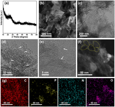 | ||
| Fig. 1 (a) XRD pattern, (b) SEM image, (c)–(e) TEM images, (f) STEM image, and (g) corresponding elemental mappings of 3D-NPOC. | ||
X-Ray photoelectron spectroscopy (XPS) is further performed to study the detailed chemical environments of the 3D-NPOC surface. The full-XPS spectrum of 3D-NPOC as shown in Fig. 2a indicating the co-existence of C, N, O, and P elements in such a carbon material, which is coincident with the analysis result of elemental mapping. The C 1s spectrum for 3D-NPOC (Fig. 2b) presents peaks at 284.8 eV, 285.8 eV, 286.8 eV, and 289.8 eV, which are assigned to the C–C, C–P, C–N, and O–C![[double bond, length as m-dash]](https://www.rsc.org/images/entities/char_e001.gif) O, respectively.38 Among them, the C–C peak corresponds to the graphitic carbon formed from the carbonization of tannic acid, and the presence of C–P, C–N, and O–C
O, respectively.38 Among them, the C–C peak corresponds to the graphitic carbon formed from the carbonization of tannic acid, and the presence of C–P, C–N, and O–C![[double bond, length as m-dash]](https://www.rsc.org/images/entities/char_e001.gif) O bonds indicates that elements P, N, and O are successfully doped into the carbon material. Fig. 2c shows the N 1s XPS spectrum of 3D-NPOC, in which nitrogen species can mainly be fitted into four forms: pyridine nitrogen (42.6%), pyrrole nitrogen (36.35%), graphite nitrogen (12.48%), and oxidized nitrogen (8.57%), which locate at 398.3 eV, 400.1 eV, 402.5 eV, and 405.5 eV, respectively, further revealing that the N element is successfully doped into the carbon skeleton.39 In Fig. 2d, we can see that there are two forms of oxygen at 531.5 eV and 532.8 eV, mainly along with the phenol-O and ether-O species, respectively.40 As presented in Fig. 2e of the P 2p XPS spectrum, there are P–O–C, P–C, and P–O species at 128.4 eV, 132.5 eV, and 136.1 eV, respectively, which further proves that the P element is successfully incorporated into the carbon skeleton.41 Moreover, the signal of Co and Ni atoms can’t be observed from the Co 2p and Ni 2p XPS spectra (Fig. S1, ESI†), indicating no residual Ni and Co in the 3D-NPOC. Of note, the foreign atom dopant can greatly optimize the electronic structure of the carbon skeleton to enhance its electrocatalytic performance.18,25,28,42 All in all, the obtained 3D-NPOC possesses interconnected 3D porous nanostructures with the configuration of N, P, and O species, thus being considered to be an active electrocatalyst for the HER, OER, and ORR.
O bonds indicates that elements P, N, and O are successfully doped into the carbon material. Fig. 2c shows the N 1s XPS spectrum of 3D-NPOC, in which nitrogen species can mainly be fitted into four forms: pyridine nitrogen (42.6%), pyrrole nitrogen (36.35%), graphite nitrogen (12.48%), and oxidized nitrogen (8.57%), which locate at 398.3 eV, 400.1 eV, 402.5 eV, and 405.5 eV, respectively, further revealing that the N element is successfully doped into the carbon skeleton.39 In Fig. 2d, we can see that there are two forms of oxygen at 531.5 eV and 532.8 eV, mainly along with the phenol-O and ether-O species, respectively.40 As presented in Fig. 2e of the P 2p XPS spectrum, there are P–O–C, P–C, and P–O species at 128.4 eV, 132.5 eV, and 136.1 eV, respectively, which further proves that the P element is successfully incorporated into the carbon skeleton.41 Moreover, the signal of Co and Ni atoms can’t be observed from the Co 2p and Ni 2p XPS spectra (Fig. S1, ESI†), indicating no residual Ni and Co in the 3D-NPOC. Of note, the foreign atom dopant can greatly optimize the electronic structure of the carbon skeleton to enhance its electrocatalytic performance.18,25,28,42 All in all, the obtained 3D-NPOC possesses interconnected 3D porous nanostructures with the configuration of N, P, and O species, thus being considered to be an active electrocatalyst for the HER, OER, and ORR.
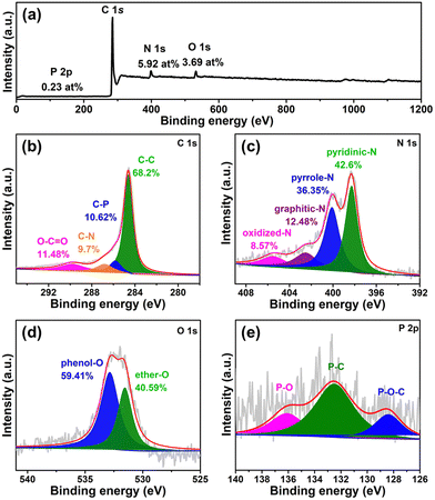 | ||
| Fig. 2 (a) XPS survey spectrum of 3D-NPOC. High-resolution XPS spectra of (b) C 1s, (c) N 1s, (d) O 1s, and (e) P 2p for 3D-NPOC. | ||
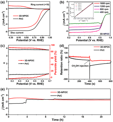
The catalytic performance for the ORR of 3D-NPOC and commercial benchmark Pt/C are evaluated by polarization curve (LSV) in 0.1 M KOH solution. As shown in Fig. 3a, the half-wave potential (E1/2) and limiting current density of 3D-NPOC are 0.83 eV and 5.1 mA cm−2, respectively, which are on par with those of the Pt/C catalyst (0.86 eV). To understand the reaction path of the 3D-NPOC catalyst, the various LSV curves under different rotation speeds are further tested (Fig. 3b), and five different potentials from 0.25 to 0.45 V are selected in the platform area. The fitting results show that the five straight-line slopes are nearly coincident (inset in Fig. 3b), indicating that 3D-NPOC is the first-order kinetic process. In addition, according to the Koutecky–Levich (K–L) equation, the average electron transfer number (n) is about 4.0 (Fig. 3c), revealing the ideal four-electron reaction pathway of 3D-NPOC for the ORR.43 Moreover, the peroxide yield for the 3D-NPOC is always less than 10%, much below benchmark Pt/C, which significantly confirms its superior catalytic efficiency for the ORR (Fig. 3c). To analyze the methanol toxicity resistance of 3D-NPOC, the current change curve of adding 3 M CH3OH methanol to 0.1 M KOH saturated with O2 is recorded, as shown in Fig. 3d. Note that the current of 3D-NPOC drops to 74% relative to the initial current after testing for 400 s, much higher than 47% of Pt/C. In addition, the recorded curve of 3D-NPOC shows a relatively small current fluctuation after adding methanol in comparison with commercial benchmark Pt/C, greatly revealing the high oxidation resistance of 3D-NPOC. The long-term durability of 3D-NPOC and Pt/C are also investigated as presented in Fig. 3e, greatly demonstrating that the electrocatalytic stability of 3D-NPOC is much better than that of Pt/C.
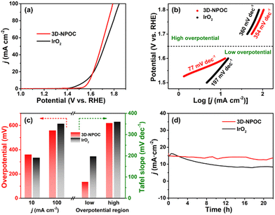
The OER performance of 3D-NPOC in 1 M KOH solution is also studied by the classical three-electrode system. The results are shown in Fig. 4a, c and Fig. S2 (ESI†), where 3D-NPOC has an overpotential of 360 mV at 10 mA cm−2 current density, slightly inferior to commercial IrO2 (334 mV), but better than that of nickel form (NF). Note that the catalytic activity of 3D-NPOC will suppress the commercial IrO2 when the current density exceeds 18 mA cm−2. At a high current density of 100 mA cm−2, the overpotential of 3D-NPOC is 559 mV, much smaller than that of commercial IrO2 (614 mV). Furthermore, their corresponding Tafel curves in the low- and high-overpotential areas are analyzed (Fig. 4b and c).44 At the low overpotential area from 1.5 to 1.6 V vs. RHE, the Tafel slope of 3D-NPOC is 77 mV dec−1, much smaller than that of commercial IrO2 (197 mV dec−1). At the high overpotential area from 1.7 to 1.8 V vs. RHE, the Tafel slope of 3D-NPOC is 354 mV dec−1, also lower than that of commercial IrO2 (360 mV dec−1). These results reveal that the OER reaction kinetics of 3D-NPOC is higher than that of commercial IrO2 whether at low or high current densities, indicating its potential practical application value. Fig. 4d is the time–current density curve of 3D-NPOC and commercial IrO2. It can be seen that after 20 h of continuous testing, the current attenuation degree of 3D-NPOC is less than that of commercial IrO2. Therefore, the above results indicate that the OER performance of 3D-NPOC is superior to commercial IrO2. The electrochemical surface areas (ECSA) are tested by a cyclic voltammetry method in non-faradaic regions (Fig. S3, ESI†), suggesting that 3D-NPOC has a higher intrinsic active surface area than the IrO2 benchmark. Moreover, the Nyquist plot indicates that 3D-NPOC possesses a faster charge transfer rate (Fig. S4, ESI†).
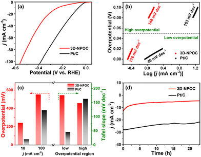
Furthermore, the alkaline HER performance of 3D-NPOC is also investigated by using the typical three-electrode cell. At different current densities (10 and 100 mA cm−2), the 3D-NPOC can exhibit reasonably good catalytic activities (241 and 552 mV) in comparison with commercial Pt/C (63 and 380 mV) for the HER in 1.0 M KOH (Fig. 5a, c and Fig. S5, ESI†). More notably, as shown in Fig. 5b and c, 3D-NPOC possesses a higher Tafel slope of 176 mV dec−1 than that of benchmark Pt/C (46 mV dec−1) at the low overpotential region from 0 to 50 mV. While at the high overpotential region from 50 to 100 mV, 3D-NPOC can deliver a lower Tafel slope of 148 mV dec−1 relative to benchmark Pt/C (163 mV dec−1), indicating superior reaction kinetics of 3D-NPOC for the alkaline HER. In addition, 3D-NPOC can also exhibit comparative long-term stability compared to commercial Pt/C as presented in Fig. 5d. The above analysis results imply that the obtained 3D-NPOC has a high potential for commercial application, especially under high current densities.
Benefitting from excellent bifunctional catalytic activities for the ORR and OER, we assembled the 3D-NPOC into the cathodes in zinc–air batteries as illustrated in Fig. 6a to evaluate their performance under practical operation conditions, as well as Pt/C + IrO2 used as the reference, in which 6.0 M KOH and zinc acetate dissolved in 6.0 M KOH are used as the electrolyte for primary zinc–air and rechargeable batteries, respectively.45 As shown in Fig. 6b, 3D-NPOC-based batteries show voltage plateaus of ≈1.2 V at a current density of 20 mA cm−2, which are similar to Pt/C-based batteries. Moreover, the 3D-NPOC-based batteries can deliver a high specific capacity of 332 mA h gZn−1 at 20 mA cm−2, better than that of Pt/C‖IrO2-based batteries (317 mA h gZn−1). For rechargeable zinc–air batteries (Fig. 6c), at the initial stage, the sum of discharge and charge potentials of the Pt/C‖IrO2-based battery is smaller than that of the 3D-NPOC-based batteries at a current density of 20 mA cm−2, indicating the poor rechargeable properties of our catalysts relative to Pt/C‖IrO2-based batteries in this stage. Encouragingly, with extended cycle testing, the performance of the 3D-NPOC-based battery becomes good, and the sum of its discharge and charge potentials is smaller than those of the Pt/C-based battery, suggesting that the 3D-NPOC-based battery is more active under practical operating conditions. Furthermore, the 3D-NPOC-based overall water splitting in 1 M KOH delivers a low overpotential of 1.56 V at 10 mA cm−2 (Fig. S6, ESI†).
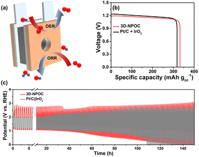 | ||
| Fig. 6 (a) The schematic diagram of a homemade zinc–air battery. (b) Specific capacities, and (c) battery cycling test of 3D-NPOC and Pt/C + IrO2-based batteries. | ||
4. Conclusions
All in all, a three dimensional N, P, O co-doped carbon framework (3D-NPOC) was prepared by using a simple annealing treatment with tannic acid as a precursor. Owing to the electronic structure optimization effect of foreign atoms and accelerated electrolyte transfer and gas diffusion derived from the interconnected 3D porous nanostructures, the obtained 3D-NPOC showed reasonable electrocatalytic performances for the ORR, OER, and HER relative to commercial benchmark Pt/C and IrO2. More importantly, the assembled zinc–air batteries with 3D-NPOC as the cathode electrode delivered a better performance than that of Pt/C‖IrO2-assembled batteries. Hence, this work may extend the scope of inexpensive metal-free multifunctional catalysts to promote the evolution of low-carbon and sustainable technologies.Author contributions
LC and YZ prepared materials and carried out experiments. ZL, LH and XL helped to analyze the experimental data. XL supervised the work. All authors contributed to revising the manuscript, approved the final version, and agreed to be accountable for all aspects of this work.Conflicts of interest
The authors declare that the research was conducted in the absence of any commercial or financial relationships that could be construed as a potential conflict of interest.Acknowledgements
We gratefully acknowledge the financial support from the Taishan Scholar Program of Shandong Province, China (ts201712045), the Natural Science Foundation of Shandong Province of China (ZR2022QB100), and the Science Foundation of Qingdao University of Science and Technology (12030430010936).Notes and references
- B. Rausch, M. D. Symes, G. Chisholm and L. Cronin, Science, 2014, 345, 1326–1330 CrossRef CAS.
- J. Zhang, Z. Zhao, Z. Xia and L. Dai, Nat. Nanotechnol., 2015, 10, 444 CrossRef CAS.
- C. Li, H. Jang, S. Liu, M. Kim, L. Hou, X. Liu and J. Cho, Adv. Energy Mater., 2022, 12, 2200029 CrossRef CAS.
- Q. Qin, H. Jang, L. Chen, G. Nam, X. Liu and J. Cho, Adv. Energy Mater., 2018, 8, 1801478 CrossRef.
- L. Hou, X. Gu, X. Cui, J. Tang, Z. Li, X. Liu and J. Cho, EES Catal., 2023, 1, 619–644 RSC.
- Z. Chen, J. Wen, C. Wang and X. Kang, Small, 2022, 18, 2204255 CrossRef CAS.
- S. Gong, M. Sun, Y. Lee, N. Becknell, J. Zhang, Z. Wang, L. Zhang and Z. Niu, Angew. Chem., Int. Ed., 2023, 62, e202214516 CrossRef CAS PubMed.
- Y. Zhang, Z. Li, L. Hou and X. Liu, Adv. Funct. Mater., 2023, 33, 2213976 CrossRef CAS.
- C. Li, H. Jang, M. Kim, L. Hou, X. Liu and J. Cho, Appl. Catal., B, 2022, 307, 121204 CrossRef CAS.
- Q. Qin, H. Jang, P. Li, B. Yuan, X. Liu and J. Cho, Adv. Energy Mater., 2019, 9, 1803312 CrossRef.
- S. Jo, M. Kim, K. B. Lee, H. Choi, L. Zhang and J. I. Sohn, Adv. Energy Mater., 2023, e2301420 CrossRef.
- X. Jiang, H. Jang, S. Liu, Z. Li, M. G. Kim, C. Li, Q. Qin, X. Liu and J. Cho, Angew. Chem., Int. Ed., 2021, 60, 4110 CrossRef CAS PubMed.
- K. Huang, J. Xia, Y. Lu, B. Zhang, W. Shi, X. Cao, X. Zhang, L. M. Woods, C. Han, C. Chen, T. Wang, J. Wu and Y. Huang, Adv. Sci., 2023, 10, 2300094 CrossRef CAS PubMed.
- C. Zhou, S. Zhao, H. Meng, Y. Han, Q. Jiang, B. Wang, X. Shi, W. Zhang, L. Zhang and R. Zhang, Nano Lett., 2021, 21, 9633 CrossRef CAS.
- L. Hou, Z. Li, H. Jang, Y. wang, X. Cui, X. Gu, M. Kim, L. Feng, S. Liu and X. Liu, Adv. Energy Mater., 2023, 13, 2300177 CrossRef CAS.
- E. Luo, Y. Chu, J. Liu, Z. Shi, S. Zhu, L. Gong, J. Ge, C. H. Choi, C. Liu and W. Xing, Energy Environ. Sci., 2021, 14, 2158 RSC.
- J. Gao, H. Tao and B. Liu, Adv. Mater., 2021, 33, 2003786 CrossRef CAS PubMed.
- K. Gong, F. Du, Z. Xia, M. Durstock and L. Dai, Science, 2009, 323, 760 CrossRef CAS PubMed.
- J. Li, P. Hou, S. Zhao, C. Liu, D. Tang, M. Cheng, F. Zhang and H. Cheng, Energy Environ. Sci., 2016, 9, 3079 RSC.
- K. Qu, Y. Zheng, X. Zhang, K. Davey, S. Dai and S. Qiao, ACS Nano, 2017, 11, 7293 CrossRef CAS.
- L. Zhang, J. Xiao, H. Wang and M. Shao, ACS Catal., 2017, 7, 7855 CrossRef CAS.
- S. Huang, Y. Meng, Y. Cao, S. He, X. Li, S. Tong and M. Wu, Appl. Catal., B, 2019, 248, 239 CrossRef CAS.
- X. Zhou, Y. Mo, F. Yu, L. Liao, X. Yong, F. Zhang, D. Li, Q. Zhou, T. Sheng and H. Zhou, Adv. Funct. Mater., 2022, 33, 2209465 CrossRef.
- X. Yue, X. Qin, Y. Chen, Y. Peng, C. Liang, M. Feng, X. Qiu, M. Shao and S. Huang, Adv. Sci., 2021, 8, 2101653 CrossRef CAS PubMed.
- X. Liu and L. Dai, Nat. Rev. Mater., 2016, 1, 16064 CrossRef CAS.
- J. Zhang and L. Dai, Angew. Chem., Int. Ed., 2016, 55, 13296 CrossRef CAS.
- C. Hu and L. Dai, Adv. Mater., 2017, 29, 1604942 CrossRef.
- L. M. Dai, Y. H. Xue, L. T. Qu, H.-J. Choi and J.-B. Baek, Chem. Rev., 2015, 115, 4823 CrossRef CAS PubMed.
- Y. Ito, W. T. Cong, T. Fujita, Z. Tang and M. W. Chen, Angew. Chem., 2015, 12, 2159 CrossRef.
- L. Hou, W. Yang, Y. Li, P. Wang, B. Jiang, C. Xu, C. Zhang, G. Huang, F. Yang and Y. Li, Chem. Eng. J., 2021, 417, 129289 CrossRef CAS.
- L. Hou, W. Yang, B. Jiang, P. Wang, L. Yan, C. Zhang, G. Huang, F. Yang and Y. Li, Carbon, 2021, 183, 176 CrossRef CAS.
- L. M. Dai, Acc. Chem. Res., 2013, 46, 31 CrossRef CAS PubMed.
- Y. Jiao, Y. Zheng, M. Jaroniec and S. Z. Qiao, Chem. Soc. Rev., 2015, 44, 2060 RSC.
- L. Dai, Y. Xue, L. Qu, H. Choi and J. Baek, Chem. Rev., 2015, 115, 4823 CrossRef CAS.
- K. Gao, B. Wang, L. Tao, B. V. Cunning, Z. Zhang, S. Wang, R. S. Ruoff and L. Qu, Adv. Mater., 2019, 31, 1805121 CrossRef PubMed.
- X. Xiao, Z. Li, Y. Xiong and Y. Yang, J. Am. Chem. Soc., 2023, 145, 16548–16556 CrossRef CAS PubMed.
- Z. Tian, W. Wang, C. Dong, X. Deng and G. Wang, ACS Nano, 2023, 17, 3889 CrossRef CAS PubMed.
- F. Xiao, Z. Chen, H. Wu, Y. Wang, E. Cao, X. Lu, Y. Wu and Z. Ren, Nanoscale, 2019, 11, 23027 RSC.
- X. Li, W. Zhang, J. Cai, H. Yan, M. Cui, G. Wu and M. Li, Nano Energy, 2019, 62, 239 CrossRef CAS.
- Y. Zhang, L. Chen, L. Hou and X. Liu, Catal. Sci. Technol., 2023, 13, 910 RSC.
- S. Lu, Y. Shi, W. Zhou, Z. Zhang, F. Wu and B. Zhang, J. Am. Chem. Soc., 2022, 144, 3250 CrossRef CAS PubMed.
- J. Zhang and L. Dai, ACS Catal., 2015, 5, 7244 CrossRef CAS.
- Y. Nie, L. Li and Z. Wei, Chem. Soc. Rev., 2015, 44, 2168 RSC.
- H. Fu, M. Zhou, P. Liu, P. Liu, H. Yin, K. Sun, H. Yang, M. Al-Mamun, P. Hu, H. Wang and H. Zhao, J. Am. Chem. Soc., 2022, 144, 6028 CrossRef CAS.
- X. Liu, Y. Yuan, J. Liu, B. Liu, X. Chen, J. Ding, X. Han, Y. Deng, C. Zhong and W. Hu, Nat. Commun., 2019, 10, 4767 CrossRef PubMed.
Footnote |
| † Electronic supplementary information (ESI) available: SEM, TEM, XPS, ORR, OER, and HER performances. See DOI: https://doi.org/10.1039/d3ya00493g |
| This journal is © The Royal Society of Chemistry 2024 |


