 Open Access Article
Carbon fiber composite electrodes derived from metal organic polyhedra-18 and matrimid for hybrid supercapacitors†
Syed Fahad Bin
Haque
 ,
Yafen
Tian
 ,
Daniel W.
Tague
,
Kenneth J.
Balkus
Jr.
,
Daniel W.
Tague
,
Kenneth J.
Balkus
Jr.
 and
John P.
Ferraris
 *
*
Department of Chemistry and Biochemistry, The University of Texas at Dallas, Richardson, TX 75080-3021, USA. E-mail: ferraris@utdallas.edu
First published on 26th March 2024
Abstract
Matrimid and metal–organic polyhedra–18 (MOP-18) electrospun composite nanofibers were utilized to fabricate free-standing, electrically conducting, and high-energy density hybrid supercapacitor electrodes. Electrospinning multiple compositions of Matrimid and MOP-18 mixture followed by carbonization and activation with CO2 resulted in C/Cu/Cu2O nanocomposite fibers that exhibited an energy density of up to 12.69 W h kg−1 and a specific capacitance of 253.4 F g−1 at 1 A g−1 current density in 6 M KOH electrolyte. The high energy density of the material can be attributed to the uniform dispersion of redox-active metal/metal oxide particles facilitated by the high solubility of the MOP-18 precursor. The thermal decomposition of MOP-18 during carbonization produced volatile species that increase the surface area and porosity of the resultant carbon allowing for better access of electrolyte ions during charging/discharging. Furthermore, MOP-18 carbonization lowered the ID/IG of the composite electrodes, consistent with increased graphitization.
Introduction
The need for efficient and cost-effective electrical energy storage systems is projected to increase in the near future as a result of a shift toward renewable energy and electric transportation.1,2 A synergistic combination of electrochemical double-layer capacitors (EDLC) and pseudocapacitors (PC) known as hybrid supercapacitors promises to be a viable alternative for current and future energy storage needs. They are relatively safe, low-cost, long-lasting, and sustainable electrical energy storage systems compared to other available methods.3–5 Li-ion batteries, currently the most widely used energy storage for consumer electronics and electric vehicles, have been significantly improved in recent years, particularly in terms of energy density and associated cost.6–9 Nevertheless, the operating temperature range, low power density, relatively short cyclability, and significant fire hazard compared to other storage methods have inspired efforts to develop alternatives.10–13 EDLCs have been studied for this purpose as they have higher power density and longer cycle life compared to Li-ion batteries but their energy density is lower by several orders of magnitude.14–18 PCs based on conducting polymers and redox-active metal oxides have also been studied because they have better energy density than EDLCs. However, PCs have poor cyclability or low electrical conductivity which limits their utility.16,19–22 Hybrid supercapacitors have the potential to bring a well-balanced synergistic combination of both EDLC and pseudocapacitors to simultaneously afford superior energy density, power density, and cyclability.23–29Hybrid supercapacitor electrodes generally consist of a composite/physical mixture of carbon-based EDLC components along with a metal/metal oxide or conducting polymer pseudocapacitive component.30–35 The EDLC part of the electrode mainly contributes conductivity and power density while pseudocapacitive materials add energy density.4 Combining EDLCs and PCs in a way that enhances the other is the major challenge in designing hybrid supercapacitor electrodes. The interface between these two components plays an important role in dictating the performance and usability of the electrode material.36 Redox-active pseudocapacitive materials need high effective surface area, access to the electrolyte, and sufficient electrical conductivity to perform at full potential.37 A physical mixture of carbon and redox-active materials often fails to provide the redox-active species with all these necessities. Special structures like core–shell, 1D and 2D hybrids, intimate contact composites, and superior mixing techniques like in situ dispersion are necessary for both components to work efficiently and effectively.38–41
Numerous metal nanoparticles and metal oxides including copper have been incorporated into hybrid supercapacitors to improve energy density.42–46 The problem of dispersion of redox particles, control of particle size, and prevention of side reactions like crosslinking between carbon and metal phases has slowed the advancement of this approach. Additionally, the introduction of redox particles often reduces the available surface area of the carbon counterpart which hinders overall performance. To achieve high energy density through pseudocapacitance in carbon-based supercapacitor electrodes CuO,47–49 CuS,50 and other copper compounds and complexes have been previously studied.51,52 The difficulty of controlling particle size, especially for copper metal nanoparticles, dispersion, and integration of redox-active species has limited the desired outcome from these electrode systems. Often metal–organic frameworks (MOF) have been studied to solve this issue, but MOFs lack solubility for uniform particle dispersion.53 Metal–organic polyhedra (MOP) with long carbon chains attached to their outer shell are soluble in organic solvents and hence they can be utilized to disperse redox active metal nanoparticles.54 Additionally, thermal decomposition of MOP structures creates porosity in the electrode enhancing the surface area and electrolyte accessibility after carbonization. Metal–organic polyhedra-18 (MOP-18) was used in this study as a PC precursor and to the best of our knowledge, this work presents the first hybrid supercapacitor based on a metal–organic polyhedra derived PC component. In the outer shell, MOP-18 contains 24 dodecyl alkane chains, and in the inner core, it consists of 24 copper atoms in 12 paddle-wheel units.55,56 The long carbon chains attached to the structure render MOP-18 highly soluble in a variety of organic solvents which aided mixing with Matrimid polymer during electrospinning. MOP-18 was uniformly dispersed in the composite nanofiber, which afforded small copper and copper oxide nanoparticles after carbonization. The metal–organic structure of MOP-18 ensured a composite of Cu/Cu2O with low internal resistance. While carbonizing the electrode, the MOP-18 structure decomposed to introduce micropores which increased the electrolyte accessibility of the redox particle as well. The carbonized and CO2 activated composite of Matrimid and MOP-18 at a current density of 1 A g−1 delivers a specific capacitance of 253.3 F g−1 and an energy density of 12.69 W h kg−1 in a 6 M KOH electrolyte solution.
Experimental
Materials
Matrimid 5218 was sourced and used without further purification from Ciba Specialty Chemicals. Potassium hydroxide was purchased from Fisher Scientific. Sodium bicarbonate, 5-hydroxyisophthalic acid, 1-iodododecane, ethyl acetate, acetonitrile, methanol, copper acetate monohydrate, tetrachloroethane, and chloroform for MOP-18 synthesis were purchased and used without farther purification from Sigma-Aldrich with more than 97% purity. Dimethylformamide (DMF) and dimethylacetamide (DMAc) solvents of 99.8% purity were purchased from Sigma-Aldrich and Millipore Corporation, respectively.MOP-18 synthesis
A published procedure was used to synthesize MOP-18.55 5-Dodecoxyisophthalic acid, the linker for MOP-18 synthesis was prepared by esterification of 5-hydroxyisophthalic with ethanol, alkylating the diester's hydroxyl group followed by hydrolysis. 2.7 g of the synthesized linker were dissolved in 100 mL of DMF at 80 °C while stirring until the solution was clear. 1.5 g of copper acetate was dissolved at room temperature in 50 mL of DMF. The two solutions were mixed, and 100 mL of methanol was added to initiate precipitation. The solid precipitate was left to crystallize for 24 h at room temperature and then washed repeatedly with methanol at room temperature.56 The blue solid was dried at 60 °C for 24 h. The product MOP-18 crystals were characterized by powder XRD (Fig. S1, ESI†).MOP-18 and matrimid fiber preparation
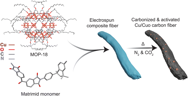
Matrimid (0.6 g) was dissolved in 3.63 mL of DMAc at room temperature to produce a 15% solution by weight. Separate solutions of MOP-18 were prepared by dissolving 0.3 g, 0.6 g, and 1.2 g of MOP-18 in 1.7 mL, 3.4 mL, and 6.8 mL of DMAc respectively at room temperature to obtain a 15 wt% solution of MOP-18. Then the Matrimid solution and MOP-18 solution were mixed to produce 2![[thin space (1/6-em)]](https://www.rsc.org/images/entities/char_2009.gif) :
:![[thin space (1/6-em)]](https://www.rsc.org/images/entities/char_2009.gif) 1, 1
1, 1![[thin space (1/6-em)]](https://www.rsc.org/images/entities/char_2009.gif) :
:![[thin space (1/6-em)]](https://www.rsc.org/images/entities/char_2009.gif) 1, and 1
1, and 1![[thin space (1/6-em)]](https://www.rsc.org/images/entities/char_2009.gif) :
:![[thin space (1/6-em)]](https://www.rsc.org/images/entities/char_2009.gif) 2 dry w/w ratios of Matrimid/MOP-18. The mixtures were stirred for 24 hours at room temperature to ensure uniformity. The resulting solution was then electrospun using a custom-built electrospinning setup. The uniformly mixed polymer solution was charged at a rate of 0.5 mL h−1. The 20 Ga blunt tip needle connected to the 10 mL syringe had a positive potential of 20 kV and had a translation motion during spinning. A rotating collecting drum covered with aluminium foil had a negative potential of 5 kV and was rotated at 300 rpm. The distance between the needle tip to the collector was maintained at 15 cm. As-spun fibers were collected and dried under vacuum at 150 °C for 24 h. To carbonize and activate the e-spun fibers, the mat was heated at 800 °C using a 5 °C min−1 heating rate and held there for 60 min under a constant N2(g) flow rate of 200 SCCM. Then CO2(g) was passed over the fibers for an additional 30 min at 800 °C in a 3
2 dry w/w ratios of Matrimid/MOP-18. The mixtures were stirred for 24 hours at room temperature to ensure uniformity. The resulting solution was then electrospun using a custom-built electrospinning setup. The uniformly mixed polymer solution was charged at a rate of 0.5 mL h−1. The 20 Ga blunt tip needle connected to the 10 mL syringe had a positive potential of 20 kV and had a translation motion during spinning. A rotating collecting drum covered with aluminium foil had a negative potential of 5 kV and was rotated at 300 rpm. The distance between the needle tip to the collector was maintained at 15 cm. As-spun fibers were collected and dried under vacuum at 150 °C for 24 h. To carbonize and activate the e-spun fibers, the mat was heated at 800 °C using a 5 °C min−1 heating rate and held there for 60 min under a constant N2(g) flow rate of 200 SCCM. Then CO2(g) was passed over the fibers for an additional 30 min at 800 °C in a 3![[thin space (1/6-em)]](https://www.rsc.org/images/entities/char_2009.gif) :
:![[thin space (1/6-em)]](https://www.rsc.org/images/entities/char_2009.gif) 1 N2 to CO2 ratio at a constant flow rate of 240 SCCM to activate the fibers (Fig. 1).
1 N2 to CO2 ratio at a constant flow rate of 240 SCCM to activate the fibers (Fig. 1).
Characterization
Numerous characterization techniques were utilized to understand the physical structure and electrochemical performance of the synthesized Matrimid/MOP-18 hybrid electrodes. The Powder X-ray diffraction patterns were collected using a Rigaku Ultima IV diffractometer (Cu Kα radiation). A Thermo Scientific DXR Raman microscope with a laser excitation wavelength of 532 nm was used to obtain the Raman spectra. X-ray photoelectron spectroscopy (XPS) measurements using a PHI Versa Probe II determined the composition of the surface elements. A monochromatic Al Kα radiation (hv = 1486.6 eV) was used to generate the photoelectrons and the spectra were collected in a hemispherical analyzer at 0.2 eV step size and a pass energy of 11 eV for survey and 23.5 eV for analysis. Fiber morphology after carbonization and activation was characterized by high-resolution transmission electron microscopy (HRTEM) JEOL JEM-2100 TEM at 200 kV. A Zeiss SUPRA 40 SEM instrument was used to collect micrographs of carbonized samples. Micromeritics ASAP 2020 was used to collect nitrogen and carbon dioxide adsorption–desorption isotherms at 77 K and 273 K respectively. The Brunauer–Emmett–Teller (BET) method was used to determine the specific surface area after carbonization and activation. The two-dimensional nonlinear density functional theory (2D NLDFT) method was used to determine the pore size distribution from the gas adsorption–desorption isotherm.57 The conductivity of carbonized and activated composite electrode materials was measured using a DP03 Alessi 4-point probe instrument paired with a QuadTech LR2000 digital milliohmmeter.Results and discussion
The SEM images in Fig. 2 show the Matrimid/MOP-18 composite fibers after carbonization and activation. Carbonized Matrimid fibers in Fig. 2(a) have a relatively smooth surface with an average diameter of about 300 nm. Copper nanoparticles are visible in Fig. 2(b–d) on the surface of the carbonized fibers that contained MOP-18. Upon carbonization, MOP-18 decomposes, producing metallic copper particles. During CO2 activation the trace amounts of oxidizing gases produced from decomposing polymer chains create an oxide layer on a portion of the particles preventing their melting and recrystallization. On the other hand, unoxidized particles undergo Ostwald ripening during the high-temperature carbonization process and grow. The 2![[thin space (1/6-em)]](https://www.rsc.org/images/entities/char_2009.gif) :
:![[thin space (1/6-em)]](https://www.rsc.org/images/entities/char_2009.gif) 1 Matrimid/MOP-18 composite in Fig. 2(b) shows a particle-decorated carbon fiber that has a fiber diameter of around 400 nm with particles on the surface that are around 100 nm. Additionally, from SEM of 1
1 Matrimid/MOP-18 composite in Fig. 2(b) shows a particle-decorated carbon fiber that has a fiber diameter of around 400 nm with particles on the surface that are around 100 nm. Additionally, from SEM of 1![[thin space (1/6-em)]](https://www.rsc.org/images/entities/char_2009.gif) :
:![[thin space (1/6-em)]](https://www.rsc.org/images/entities/char_2009.gif) 1 and 1
1 and 1![[thin space (1/6-em)]](https://www.rsc.org/images/entities/char_2009.gif) :
:![[thin space (1/6-em)]](https://www.rsc.org/images/entities/char_2009.gif) 2 Matrimid/MOP-18 samples in Fig. 2(c) and (d) respectively, redox-active copper and copper(I) oxide particles are visible indicating electrolyte accessibility.
2 Matrimid/MOP-18 samples in Fig. 2(c) and (d) respectively, redox-active copper and copper(I) oxide particles are visible indicating electrolyte accessibility.
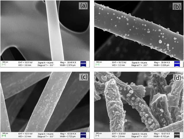 | ||
Fig. 2 SEM images of carbonized fiber from (a) Matrimid (b) 2![[thin space (1/6-em)]](https://www.rsc.org/images/entities/char_2009.gif) : :![[thin space (1/6-em)]](https://www.rsc.org/images/entities/char_2009.gif) 1 Matrimid/MOP-18 (c) 1 1 Matrimid/MOP-18 (c) 1![[thin space (1/6-em)]](https://www.rsc.org/images/entities/char_2009.gif) : :![[thin space (1/6-em)]](https://www.rsc.org/images/entities/char_2009.gif) 1 Matrimid/MOP-18 and (d) 1 1 Matrimid/MOP-18 and (d) 1![[thin space (1/6-em)]](https://www.rsc.org/images/entities/char_2009.gif) : :![[thin space (1/6-em)]](https://www.rsc.org/images/entities/char_2009.gif) 2 Matrimid/MOP-18. 2 Matrimid/MOP-18. | ||
The TEM images in Fig. 3 of carbonized composite fibers show a bimodal distribution of Cu and Cu2O particles. A histogram of particle size distribution is also presented in the ESI† in Fig. S3. More than 80% of the particles are 5–20 nm in size among which more than 60% are 10–15 nm. Particles greater than 40 nm in size account for less than 2%. All three carbonized fibers of varying composition in Fig. 3 show that both sets of particles are well dispersed in carbon.
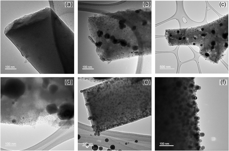 | ||
Fig. 3 TEM images of carbonized fiber from (a) Matrimid (b) 2![[thin space (1/6-em)]](https://www.rsc.org/images/entities/char_2009.gif) : :![[thin space (1/6-em)]](https://www.rsc.org/images/entities/char_2009.gif) 1 Matrimid/MOP-18 (c) and (d) 1 1 Matrimid/MOP-18 (c) and (d) 1![[thin space (1/6-em)]](https://www.rsc.org/images/entities/char_2009.gif) : :![[thin space (1/6-em)]](https://www.rsc.org/images/entities/char_2009.gif) 1 Matrimid/MOP-18 and (e) and (f) 1 1 Matrimid/MOP-18 and (e) and (f) 1![[thin space (1/6-em)]](https://www.rsc.org/images/entities/char_2009.gif) : :![[thin space (1/6-em)]](https://www.rsc.org/images/entities/char_2009.gif) 2 Matrimid/MOP-18. 2 Matrimid/MOP-18. | ||
HRTEM images of carbonized 1![[thin space (1/6-em)]](https://www.rsc.org/images/entities/char_2009.gif) :
:![[thin space (1/6-em)]](https://www.rsc.org/images/entities/char_2009.gif) 1 Matrimid/MOP-18 composites are shown in Fig. 4(a–c). The presence of particles ranging from 10 nm in diameter to 100 nm with their corresponding lattice fringes is visible in the HRTEM images. The D-spacing of 0.38 nm of carbon (002) plane in Fig. 4(a) shows the graphite has a slightly expanded interlayer spacing due to the presence of turbostratic disorder.58 Additionally, the D-spacing of 0.21 nm of copper (111) plane and 0.24 nm of copper(I) oxide (111) plane is visible from HRTEM images in Fig. 4(b) and (c) respectively.59,60 HRTEM reveals the presence of both copper and copper(I) oxide particles in the system with an indication of particles close to 10 nm in size predominantly being copper(I) oxide.
1 Matrimid/MOP-18 composites are shown in Fig. 4(a–c). The presence of particles ranging from 10 nm in diameter to 100 nm with their corresponding lattice fringes is visible in the HRTEM images. The D-spacing of 0.38 nm of carbon (002) plane in Fig. 4(a) shows the graphite has a slightly expanded interlayer spacing due to the presence of turbostratic disorder.58 Additionally, the D-spacing of 0.21 nm of copper (111) plane and 0.24 nm of copper(I) oxide (111) plane is visible from HRTEM images in Fig. 4(b) and (c) respectively.59,60 HRTEM reveals the presence of both copper and copper(I) oxide particles in the system with an indication of particles close to 10 nm in size predominantly being copper(I) oxide.
The X-ray diffraction (XRD) patterns of the carbonized Matrimid/MOP-18 composites show peaks associated with both Cu and Cu2O after carbonization and activation at 800 °C. Fig. 5 shows copper metal particles exhibiting peaks at 43.5°, 50.4°, and 74.2° which are associated with the (111), (200), and (220) planes (JCPDS No. 003–1018).61 For the Cu2O crystals, peaks shown at 36.3°, 42.4°, and 61.6° correspond to the (111), (200), and (220) peaks (JCPDS No. 05-0667).62 Partially crystalline carbon exhibited a broad peak around 24° corresponding to the (002) plane of graphene which is slightly shifted from the ideal graphite peak at 26.1° due to a turbostratic disorder.63,64 Peaks associated with Cu2O are significantly broader than peaks associated with Cu planes indicating oxide particles are smaller than metal particles.
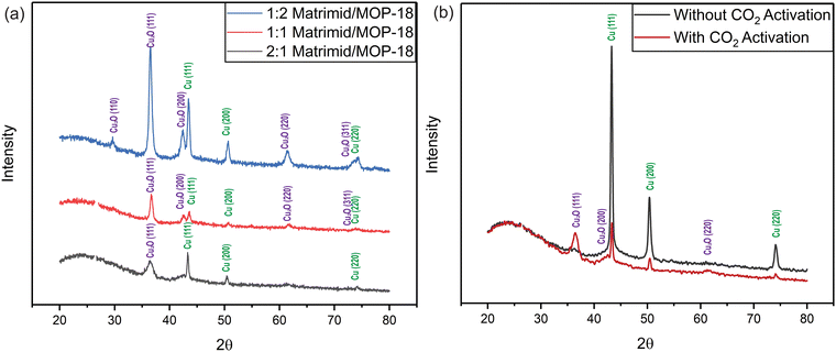 | ||
Fig. 5 (a) XRD of carbonized and activated fiber from Matrimid/MOP-18 composites. (b) XRD pattern of CO2 activated and non-activated 1![[thin space (1/6-em)]](https://www.rsc.org/images/entities/char_2009.gif) : :![[thin space (1/6-em)]](https://www.rsc.org/images/entities/char_2009.gif) 1 carbonized Matrimid/MOP-18. 1 carbonized Matrimid/MOP-18. | ||
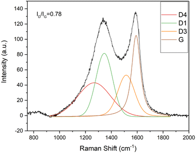
Raman spectroscopy was used to characterize the carbon component after the carbonization and activation procedure. Fig. 6 shows the fitted Raman spectrum of the carbon fibers obtained from 1![[thin space (1/6-em)]](https://www.rsc.org/images/entities/char_2009.gif) :
:![[thin space (1/6-em)]](https://www.rsc.org/images/entities/char_2009.gif) 1 Matrimid/MOP-18. The D1-band at 1350 cm−1 is associated with amorphous carbon materials and G-band at 1580 cm−1 represents graphitized carbon.65 The Raman spectra are deconvoluted into D1, D3, D4, and G band.66 Sp2–sp3 carbon bonds are represented by the D4 peak in the 1180–1290 region. The D3 peak is associated with the semicircle stretch of benzene rings in amorphous carbon.67 The deconvoluted ID/IG ratio by height is a representation of the degree of graphitization and is related to the conductivity of synthesized carbon. ID/IG ratios of carbonized and activated 2
1 Matrimid/MOP-18. The D1-band at 1350 cm−1 is associated with amorphous carbon materials and G-band at 1580 cm−1 represents graphitized carbon.65 The Raman spectra are deconvoluted into D1, D3, D4, and G band.66 Sp2–sp3 carbon bonds are represented by the D4 peak in the 1180–1290 region. The D3 peak is associated with the semicircle stretch of benzene rings in amorphous carbon.67 The deconvoluted ID/IG ratio by height is a representation of the degree of graphitization and is related to the conductivity of synthesized carbon. ID/IG ratios of carbonized and activated 2![[thin space (1/6-em)]](https://www.rsc.org/images/entities/char_2009.gif) :
:![[thin space (1/6-em)]](https://www.rsc.org/images/entities/char_2009.gif) 1, 1
1, 1![[thin space (1/6-em)]](https://www.rsc.org/images/entities/char_2009.gif) :
:![[thin space (1/6-em)]](https://www.rsc.org/images/entities/char_2009.gif) 1, and 1
1, and 1![[thin space (1/6-em)]](https://www.rsc.org/images/entities/char_2009.gif) :
:![[thin space (1/6-em)]](https://www.rsc.org/images/entities/char_2009.gif) 2 Matrimid/MOP-18 were 0.9, 0.78, and 0.86, respectively (Fig. S5 and S6, ESI†) whereas carbonized and activated Matrimid has an ID/IG ratio of 1.1 (Fig. S4, ESI†) which indicates enhanced graphitization due to the catalytic effect of present copper nanoparticles.68,69
2 Matrimid/MOP-18 were 0.9, 0.78, and 0.86, respectively (Fig. S5 and S6, ESI†) whereas carbonized and activated Matrimid has an ID/IG ratio of 1.1 (Fig. S4, ESI†) which indicates enhanced graphitization due to the catalytic effect of present copper nanoparticles.68,69
Fig. 7(a) shows the deconvoluted XPS spectra of carbon in the carbonized 1![[thin space (1/6-em)]](https://www.rsc.org/images/entities/char_2009.gif) :
:![[thin space (1/6-em)]](https://www.rsc.org/images/entities/char_2009.gif) 1 Matrimid/MOP-18 composite. Peaks appear at 284.5, 285.2, 286.3, 288.4, and 291 eV representing C
1 Matrimid/MOP-18 composite. Peaks appear at 284.5, 285.2, 286.3, 288.4, and 291 eV representing C![[double bond, length as m-dash]](https://www.rsc.org/images/entities/char_e001.gif) C, C–C, C–O–C, C
C, C–C, C–O–C, C![[double bond, length as m-dash]](https://www.rsc.org/images/entities/char_e001.gif) O, and the carbon π–π* satellite, respectively. The presence of the π–π* satellite peak indicates electrically conducting graphitic carbon materials as it arises from delocalized π-bond electrons. XPS spectra of copper show the presence of copper (0) and copper (I) 2p3/2 and 2p1/2 peaks at 932.6 and 952.5 eV.61,70,71 The absence of any strong satellite peak indicates that no CuO is present in the system.72
O, and the carbon π–π* satellite, respectively. The presence of the π–π* satellite peak indicates electrically conducting graphitic carbon materials as it arises from delocalized π-bond electrons. XPS spectra of copper show the presence of copper (0) and copper (I) 2p3/2 and 2p1/2 peaks at 932.6 and 952.5 eV.61,70,71 The absence of any strong satellite peak indicates that no CuO is present in the system.72
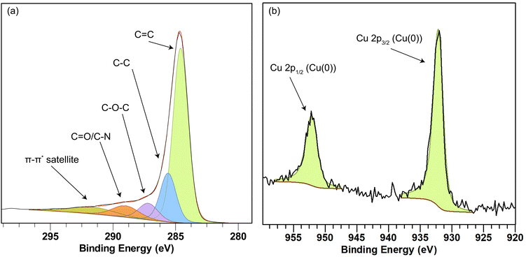 | ||
Fig. 7 XPS spectra of carbon (a) and copper (b) present in carbonized 1![[thin space (1/6-em)]](https://www.rsc.org/images/entities/char_2009.gif) : :![[thin space (1/6-em)]](https://www.rsc.org/images/entities/char_2009.gif) 1 Matrimid/MOP-18 composite. 1 Matrimid/MOP-18 composite. | ||
Fig. 8(a) shows the N2 adsorption–desorption isotherm of carbonized Matrimid and three Matrimid/MOP-18 composites. The isotherms show a type IV hysteresis with substantial gas adsorption in the low-pressure region indicating the presence of both mesopores and micropores. The CO2 adsorption isotherm was also collected for all the samples as shown in ESI† Fig. S7. The corresponding pore size distribution obtained by the 2D NLDFT method combining both the N2 and CO2 adsorption–desorption isotherms is shown in Fig. 8(b). There is mesoporosity in the samples but most of the porosity for all the composites lies in the microporous region (≤20 Å). The specific surface area of carbonized and activated Matrimid was found to be 377 m2 g−1 which increased with the addition of MOP-18 to 444 m2 g−1 in the case of 1![[thin space (1/6-em)]](https://www.rsc.org/images/entities/char_2009.gif) :
:![[thin space (1/6-em)]](https://www.rsc.org/images/entities/char_2009.gif) 1 Matrimid/MOP-18. The surface area of the electrode materials increased after adding MOP-18 due to porosity generated by the decomposition of MOP-18 at high temperatures.56,73–75 The surface areas for 2
1 Matrimid/MOP-18. The surface area of the electrode materials increased after adding MOP-18 due to porosity generated by the decomposition of MOP-18 at high temperatures.56,73–75 The surface areas for 2![[thin space (1/6-em)]](https://www.rsc.org/images/entities/char_2009.gif) :
:![[thin space (1/6-em)]](https://www.rsc.org/images/entities/char_2009.gif) 1 and 1
1 and 1![[thin space (1/6-em)]](https://www.rsc.org/images/entities/char_2009.gif) :
:![[thin space (1/6-em)]](https://www.rsc.org/images/entities/char_2009.gif) 2 carbonized and activated Matrimid/MOP-18 were 268 m2 g−1 and 564 m2 g−1, respectively. Fig. 8(b) shows the total amount of microporosity increases with the increasing amount of MOP-18 in the composite. The pore size distribution shows a set of pores at 3.8 Å and another set of pores at 5.6 Å. Carbonized Matrimid had the smallest amount of porosity at 3.8 Å and did not have any at 5.6 Å. The increase in the surface area and microporosity demonstrates the benefit of adding redox particles in the form of metal–organic polyhedral precursors. The pore sizes and distribution in the synthesized composites are compatible with the smaller sized electrolyte ions present in aqueous KOH solution.76
2 carbonized and activated Matrimid/MOP-18 were 268 m2 g−1 and 564 m2 g−1, respectively. Fig. 8(b) shows the total amount of microporosity increases with the increasing amount of MOP-18 in the composite. The pore size distribution shows a set of pores at 3.8 Å and another set of pores at 5.6 Å. Carbonized Matrimid had the smallest amount of porosity at 3.8 Å and did not have any at 5.6 Å. The increase in the surface area and microporosity demonstrates the benefit of adding redox particles in the form of metal–organic polyhedral precursors. The pore sizes and distribution in the synthesized composites are compatible with the smaller sized electrolyte ions present in aqueous KOH solution.76
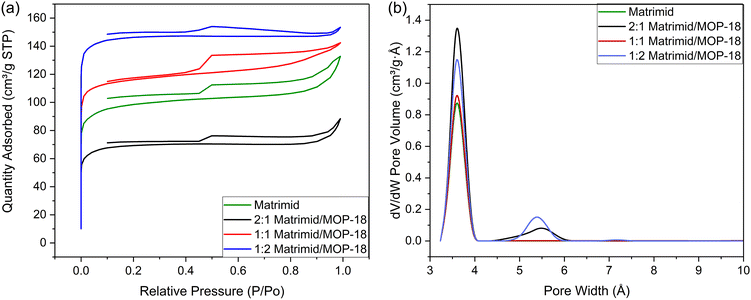 | ||
| Fig. 8 (a) N2 adsorption–desorption isotherm and (b) pore size distribution of synthesized Matrimid and Matrimid/MOP-18 carbonized fibers. | ||
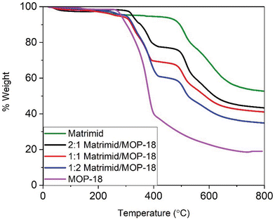
Fig. 9 shows the thermogravimetric analysis (TGA) of Matrimid and Matrimid/MOP-18 composites fibers under nitrogen gas. MOP-18 starts to degrade around 300 °C and Matrimid starts to lose mass around 450 °C. Matrimid carbonizes completely before 900 °C after losing 45% of its mass. As MOP-18 loses about 80% of its mass before reaching 500 °C, the char yield of composite fibers is less than Matrimid-only fibers. The carbonized mass of the composite fibers is 55%, 42%, 39%, and 33.5% of the original mass of Matrimid and 2![[thin space (1/6-em)]](https://www.rsc.org/images/entities/char_2009.gif) :
:![[thin space (1/6-em)]](https://www.rsc.org/images/entities/char_2009.gif) 1, 1
1, 1![[thin space (1/6-em)]](https://www.rsc.org/images/entities/char_2009.gif) :
:![[thin space (1/6-em)]](https://www.rsc.org/images/entities/char_2009.gif) 1, and 1
1, and 1![[thin space (1/6-em)]](https://www.rsc.org/images/entities/char_2009.gif) :
:![[thin space (1/6-em)]](https://www.rsc.org/images/entities/char_2009.gif) 2 Matrimid/MOP composite fibers, respectively after heating them to 800 °C under N2.
2 Matrimid/MOP composite fibers, respectively after heating them to 800 °C under N2.
All the electrode materials are characterized in electrochemical tests by fabricating T-cells where Matrimid/MOP-18 composite electrode materials are used as a working electrode. A carbonized and CO2-activated 4![[thin space (1/6-em)]](https://www.rsc.org/images/entities/char_2009.gif) :
:![[thin space (1/6-em)]](https://www.rsc.org/images/entities/char_2009.gif) 1 PAN/PMMA fiber mat was used as the counter electrode to fabricate asymmetric cells. 6 M KOH was used as an electrolyte and a PTFE membrane was used as the separator during cell fabrication. Fig. 10 shows that the 1
1 PAN/PMMA fiber mat was used as the counter electrode to fabricate asymmetric cells. 6 M KOH was used as an electrolyte and a PTFE membrane was used as the separator during cell fabrication. Fig. 10 shows that the 1![[thin space (1/6-em)]](https://www.rsc.org/images/entities/char_2009.gif) :
:![[thin space (1/6-em)]](https://www.rsc.org/images/entities/char_2009.gif) 1 Matrimid/MOP-18 shows the highest energy density versus power density. Carbonized Matrimid shows the lowest performance among all the composites in most test conditions except 1
1 Matrimid/MOP-18 shows the highest energy density versus power density. Carbonized Matrimid shows the lowest performance among all the composites in most test conditions except 1![[thin space (1/6-em)]](https://www.rsc.org/images/entities/char_2009.gif) :
:![[thin space (1/6-em)]](https://www.rsc.org/images/entities/char_2009.gif) 2 Matrimid/MOP-18 composite at higher power density.
2 Matrimid/MOP-18 composite at higher power density.
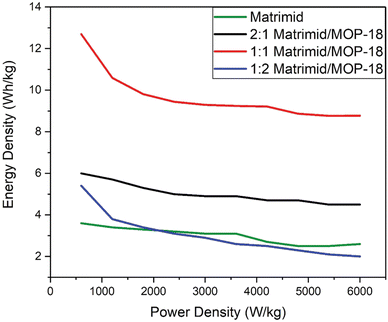 | ||
Fig. 10 Power density vs energy density graph from two electrode galvanostatic charge–discharge experiment of carbonized and activated Matrimid and 2![[thin space (1/6-em)]](https://www.rsc.org/images/entities/char_2009.gif) : :![[thin space (1/6-em)]](https://www.rsc.org/images/entities/char_2009.gif) 1, 1 1, 1![[thin space (1/6-em)]](https://www.rsc.org/images/entities/char_2009.gif) : :![[thin space (1/6-em)]](https://www.rsc.org/images/entities/char_2009.gif) 1 and 1 1 and 1![[thin space (1/6-em)]](https://www.rsc.org/images/entities/char_2009.gif) : :![[thin space (1/6-em)]](https://www.rsc.org/images/entities/char_2009.gif) 2 Matrimid/MOP-18 composites. 2 Matrimid/MOP-18 composites. | ||
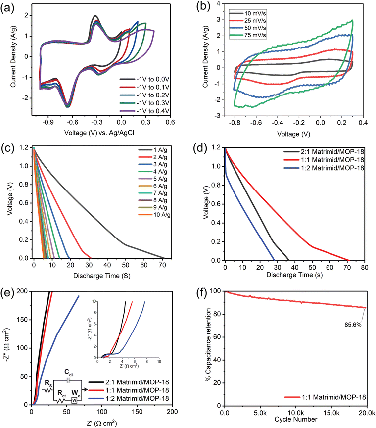
Fig. 11(a) shows multiple scanning starting from a potential of –1 V to a higher potential of 0 V to 0.5 V successively in a three-electrode setup where the reference electrode is Ag/AgCl in a saturated KCl solution. The purpose of the study was to find where the redox activity occurs and how many oxidation-state changes the redox-active particles are going through during each cycle. It shows the neutral copper particles oxidize to a (+1) oxidation state at −0.3 V and further oxidize to a (+2) oxidation state at 0.15 V. During the reversed cycling potential, the particles reduce back to (+1) at a voltage of −0.3 V and further reduce to an oxidation state of (0) at −0.65 V. Metal particles go through these successive faradaic transitions according to the mechanism presented in reference No. 55.77,78
Fig. 11(b) shows a two-electrode cyclic voltammogram of 1![[thin space (1/6-em)]](https://www.rsc.org/images/entities/char_2009.gif) :
:![[thin space (1/6-em)]](https://www.rsc.org/images/entities/char_2009.gif) 1 Matrimid/MOP-18 at scan rates of 10, 25, 50, and 75 mV s−1. The voltammograms display a nearly box-like shape overlaid with broad peaks from redox activity. Three-electrode cyclic voltammogram in Fig. 11(a) shows the redox active particles present in the electrode participate in faradaic reaction at a negative potential vs. Ag/AgCl reference electrode. Hence, the redox-active working electrode is used as the negative electrode in the experiment, and a mostly negative potential window is chosen to allow them to contribute to the current response.79 Since peaks resulting from redox activity visible in the CVs complicate the calculation of capacitance, energy density, and power density, galvanostatic charge–discharge experiments were utilized to calculate these performance metrics.
1 Matrimid/MOP-18 at scan rates of 10, 25, 50, and 75 mV s−1. The voltammograms display a nearly box-like shape overlaid with broad peaks from redox activity. Three-electrode cyclic voltammogram in Fig. 11(a) shows the redox active particles present in the electrode participate in faradaic reaction at a negative potential vs. Ag/AgCl reference electrode. Hence, the redox-active working electrode is used as the negative electrode in the experiment, and a mostly negative potential window is chosen to allow them to contribute to the current response.79 Since peaks resulting from redox activity visible in the CVs complicate the calculation of capacitance, energy density, and power density, galvanostatic charge–discharge experiments were utilized to calculate these performance metrics.
Fig. 11(c) shows a 2-electrode galvanostatic charge–discharge (GCD) of 1![[thin space (1/6-em)]](https://www.rsc.org/images/entities/char_2009.gif) :
:![[thin space (1/6-em)]](https://www.rsc.org/images/entities/char_2009.gif) 1 Matrimid/MOP-18 from 1–10 A g−1 current density. The working electrode was used as a negative electrode in an asymmetric cell to allow redox reactions in the negative potential region evident from CV. The GCD shows deviation from linearity caused by redox activity at low current density in the low voltage region. Voltage drop in the GCD is relatively low compared to other reported copper metal and oxide and carbon-based electrodes except 1
1 Matrimid/MOP-18 from 1–10 A g−1 current density. The working electrode was used as a negative electrode in an asymmetric cell to allow redox reactions in the negative potential region evident from CV. The GCD shows deviation from linearity caused by redox activity at low current density in the low voltage region. Voltage drop in the GCD is relatively low compared to other reported copper metal and oxide and carbon-based electrodes except 1![[thin space (1/6-em)]](https://www.rsc.org/images/entities/char_2009.gif) :
:![[thin space (1/6-em)]](https://www.rsc.org/images/entities/char_2009.gif) 2 carbonized Matrimid/MOP-18 composite.80,81
2 carbonized Matrimid/MOP-18 composite.80,81
Fig. 11(d) shows a comparison of galvanostatic discharge between all three composites at 1 A g−1 current density. From this study, it is seen that the 1![[thin space (1/6-em)]](https://www.rsc.org/images/entities/char_2009.gif) :
:![[thin space (1/6-em)]](https://www.rsc.org/images/entities/char_2009.gif) 1 Matrimid/MOP-18 composite holds the most amount of charge at this current density, taking the longest time to discharge from 1.2 V to 0 V at 1 A g−1 current density. The 2
1 Matrimid/MOP-18 composite holds the most amount of charge at this current density, taking the longest time to discharge from 1.2 V to 0 V at 1 A g−1 current density. The 2![[thin space (1/6-em)]](https://www.rsc.org/images/entities/char_2009.gif) :
:![[thin space (1/6-em)]](https://www.rsc.org/images/entities/char_2009.gif) 1 Matrimid/MOP-18 discharges twice as fast since it does not have as much redox capability as the 1
1 Matrimid/MOP-18 discharges twice as fast since it does not have as much redox capability as the 1![[thin space (1/6-em)]](https://www.rsc.org/images/entities/char_2009.gif) :
:![[thin space (1/6-em)]](https://www.rsc.org/images/entities/char_2009.gif) 1 composite. Even though the 1
1 composite. Even though the 1![[thin space (1/6-em)]](https://www.rsc.org/images/entities/char_2009.gif) :
:![[thin space (1/6-em)]](https://www.rsc.org/images/entities/char_2009.gif) 2 Matrimid/MOP-18 should have the highest amount of redox capability, its high impedance visible from EIS limits its electrochemical performance.
2 Matrimid/MOP-18 should have the highest amount of redox capability, its high impedance visible from EIS limits its electrochemical performance.
Its higher resistance is also evident from the IR drop visible in the galvanostatic charge–discharge experiment. At 1 A g−1, the 1![[thin space (1/6-em)]](https://www.rsc.org/images/entities/char_2009.gif) :
:![[thin space (1/6-em)]](https://www.rsc.org/images/entities/char_2009.gif) 1 Matrimid/MOP-18 composite shows a specific capacitance of 253.3 F g−1, an energy density of 12.69 W h kg−1, and a power density of 600 W kg−1. 1
1 Matrimid/MOP-18 composite shows a specific capacitance of 253.3 F g−1, an energy density of 12.69 W h kg−1, and a power density of 600 W kg−1. 1![[thin space (1/6-em)]](https://www.rsc.org/images/entities/char_2009.gif) :
:![[thin space (1/6-em)]](https://www.rsc.org/images/entities/char_2009.gif) 2 Matrimid/MOP-18 composite however at the same condition shows a capacitance of 108.2 F g−1 and an energy density of 5.4 at a power density of 600 W kg−1. 2
2 Matrimid/MOP-18 composite however at the same condition shows a capacitance of 108.2 F g−1 and an energy density of 5.4 at a power density of 600 W kg−1. 2![[thin space (1/6-em)]](https://www.rsc.org/images/entities/char_2009.gif) :
:![[thin space (1/6-em)]](https://www.rsc.org/images/entities/char_2009.gif) 1 Matrimid/MOP-18, on the other hand, shows a specific capacitance of 120.5 F g−1 and an energy density of 6 W h kg−1 at a power density of 600 W kg−1.
1 Matrimid/MOP-18, on the other hand, shows a specific capacitance of 120.5 F g−1 and an energy density of 6 W h kg−1 at a power density of 600 W kg−1.
Electrochemical impedance spectroscopy (EIS) overlays of all three composites are shown in Fig. 11(e) from 100 kHz to 0.01 Hz frequency with a focused high-frequency region in the inset. The Randles Cell circuit model was employed to fit the impedance spectra of the electrode composites, incorporating an equivalent resistance or solution resistance (Rs), a double-layer capacitor (Cdl), a charge-transfer resistance (Rct) which is proportional to the diameter of the semicircle at the intermediate frequency region on a Nyquist plot, and a Warburg component, which represents the diffusion driven impedance for faradaic processes. The Rs, Cdl, and Rct values of all three carbonized and activated Matrimid/MOP-18 composites are given in Table 2.
The 1![[thin space (1/6-em)]](https://www.rsc.org/images/entities/char_2009.gif) :
:![[thin space (1/6-em)]](https://www.rsc.org/images/entities/char_2009.gif) 1 Matrimid/MOP-18 composite exhibited the smallest semicircle on the Nyquist plot and had the lowest Rct value. In contrast, the 1
1 Matrimid/MOP-18 composite exhibited the smallest semicircle on the Nyquist plot and had the lowest Rct value. In contrast, the 1![[thin space (1/6-em)]](https://www.rsc.org/images/entities/char_2009.gif) :
:![[thin space (1/6-em)]](https://www.rsc.org/images/entities/char_2009.gif) 2 Matrimid/MOP-18 composite demonstrated both the highest Rs and Rct values. Consequently, despite having the highest relative amounts of redox-active particles by mass, its performance was inferior to the 1
2 Matrimid/MOP-18 composite demonstrated both the highest Rs and Rct values. Consequently, despite having the highest relative amounts of redox-active particles by mass, its performance was inferior to the 1![[thin space (1/6-em)]](https://www.rsc.org/images/entities/char_2009.gif) :
:![[thin space (1/6-em)]](https://www.rsc.org/images/entities/char_2009.gif) 1 Matrimid/MOP-18 composite. This observation underscores the importance of optimizing the ratio of components in the composite to achieve superior performance.
1 Matrimid/MOP-18 composite. This observation underscores the importance of optimizing the ratio of components in the composite to achieve superior performance.
Fig. 11(f) shows capacitance retention with cycle numbers for the 1![[thin space (1/6-em)]](https://www.rsc.org/images/entities/char_2009.gif) :
:![[thin space (1/6-em)]](https://www.rsc.org/images/entities/char_2009.gif) 1 Matrimid/MOP-18 composite. The experiment was done at 5 A g−1 current density and the cell was charged and discharged between 1.2 V to 0.6 V repeatedly. The cycling stability test shows the 1
1 Matrimid/MOP-18 composite. The experiment was done at 5 A g−1 current density and the cell was charged and discharged between 1.2 V to 0.6 V repeatedly. The cycling stability test shows the 1![[thin space (1/6-em)]](https://www.rsc.org/images/entities/char_2009.gif) :
:![[thin space (1/6-em)]](https://www.rsc.org/images/entities/char_2009.gif) 1 composite has a retention of more than 85% capacitance after 20
1 composite has a retention of more than 85% capacitance after 20![[thin space (1/6-em)]](https://www.rsc.org/images/entities/char_2009.gif) 000 cycles. The electrode material shows higher cyclability compared to relevant other studies referred to here.69,80,81,87 A comparison of electrochemical performance metrics between previously reported similar composite electrodes and those of this work for hybrid supercapacitors is presented in Table 1.88,89 Two-electrode and three-electrode cyclic voltammograms and galvanostatic charge–discharge plots of studied composites and Matrimid electrodes after carbonization and activation are also presented in Fig. S9–S15 with performance metrics in Tables S1–S4 (ESI†).
000 cycles. The electrode material shows higher cyclability compared to relevant other studies referred to here.69,80,81,87 A comparison of electrochemical performance metrics between previously reported similar composite electrodes and those of this work for hybrid supercapacitors is presented in Table 1.88,89 Two-electrode and three-electrode cyclic voltammograms and galvanostatic charge–discharge plots of studied composites and Matrimid electrodes after carbonization and activation are also presented in Fig. S9–S15 with performance metrics in Tables S1–S4 (ESI†).
![[thin space (1/6-em)]](https://www.rsc.org/images/entities/char_2009.gif) :
:![[thin space (1/6-em)]](https://www.rsc.org/images/entities/char_2009.gif) 1 Matrimid/MOP-18 supercapacitor electrodes with other reported studies
1 Matrimid/MOP-18 supercapacitor electrodes with other reported studies
| Material | Electrolyte | Specific capacitance | Voltage window | Energy density (W h kg−1) | Power density (W kg−1) | Cyclic stability | Ref. |
|---|---|---|---|---|---|---|---|
| ZIF-8/PAN | PVA: 1 M H2SO4 | 64.0 F g−1 at 1 A g−1 | 0–1.0 | 7.9 | 219 | 90% (10![[thin space (1/6-em)]](https://www.rsc.org/images/entities/char_2009.gif) 000) 000) |
82 |
| ZIF-8, BDBA | 6 M KOH | 242 F g−1 at 1 A g−1 | 0–1.0 | 8.4 | 500 | 99.7% (8000) | 83 |
| CNF/Ni-CAT | 2 M KOH | 68.58 F g−1 at 0.5 A g−1 | 0–1.4 | 18.67 | 297.12 | 106% (5000) | 84 |
| ZIF-67/thiourea | PVA: 1 M H2SO4 | 103 F g−1 at 0.5 A g−1 | 0–1.0 | 14.3 | 250 | 107% (3000) | 85 |
| Co3O4 | 2 M KOH | 150 F g at 1 A g−1 | 0–0.5 | — | — | 106% (3000) | 86 |
| MOP-18/CNF | 6 M KOH | 253.4 F g−1 at 1 A g−1 | 0–1.2 | 12.69 | 600 | 85.6% (20![[thin space (1/6-em)]](https://www.rsc.org/images/entities/char_2009.gif) 000) 000) |
This work |
2![[thin space (1/6-em)]](https://www.rsc.org/images/entities/char_2009.gif) : :![[thin space (1/6-em)]](https://www.rsc.org/images/entities/char_2009.gif) 1 Matrimid/MOP-18 1 Matrimid/MOP-18 |
1![[thin space (1/6-em)]](https://www.rsc.org/images/entities/char_2009.gif) : :![[thin space (1/6-em)]](https://www.rsc.org/images/entities/char_2009.gif) 1 Matrimid/MOP-18 1 Matrimid/MOP-18 |
1![[thin space (1/6-em)]](https://www.rsc.org/images/entities/char_2009.gif) : :![[thin space (1/6-em)]](https://www.rsc.org/images/entities/char_2009.gif) 2 Matrimid/MOP-18 2 Matrimid/MOP-18 |
|
|---|---|---|---|
| R s | 0.43445 | 0.69 | 0.98 |
| C dl | 2.86 × 10⁻⁶ | 6.02 × 10⁻⁵ | 5.83 × 10⁻⁶ |
| R ct | 0.81955 | 0.27571 | 1.32158 |
Conclusions
In summary, C/Cu/Cu2O nanofiber composites were synthesized by electrospinning and carbonizing Matrimid/MOP-18 solutions. CO2 activation was used to increase the surface area of synthesized electrode materials. Using MOP-18 instead of other copper precursors helped to ensure uniform dispersion of nanoparticles of small dimensions. This aided in the enhanced utilization of present redox particles in the electrode materials. Also, MOP-18 helped to improve the surface area of the composite as its thermal decomposition introduces pores in the composite for better electrolyte accessibility. The energy density of 12.69 W h kg−1 at a current density of 1 A g−1 was achieved in the study in a 6 M KOH electrolyte. The method used in the study successfully illustrates the potential of materials like metal–organic polyhedra as precursors for redox-active particles to be used in electrical energy storage.Author contributions
Formal analysis, investigation, methodology software, visualization and writing – original draft, Syed Fahad Bin Haque. Conceptualization, data curation, project administration, resources, supervision and writing – review and editing, John P. Ferraris, Kenneth J. Balkus Jr; formal analysis, Yafen Tian and Daniel W. Tague.Conflicts of interest
The authors disclose that they have no conflicting financial interests.References
- P. Simon and Y. Gogotsi, Nat. Mater., 2020, 19, 1151–1163 CrossRef CAS PubMed.
- H. Sun, Y. Zhang, J. Zhang, X. Sun and H. Peng, Nat. Rev. Mater., 2017, 2, 1–12 CAS.
- M. F. El-Kady, Y. Shao and R. B. Kaner, Nat. Rev. Mater., 2016, 1, 1–14 Search PubMed.
- L. Kouchachvili, W. Yaïci and E. Entchev, J. Power Sources, 2018, 374, 237–248 CrossRef CAS.
- M. P. Down, S. J. Rowley-Neale, G. C. Smith and C. E. Banks, ACS Appl. Energy Mater., 2018, 1, 707–714 CrossRef CAS.
- S. Goriparti, E. Miele, F. De Angelis, E. Di Fabrizio, R. P. Zaccaria and C. Capiglia, J. Power Sources, 2014, 257, 421–443 CrossRef CAS.
- M. Wakihara, Mater. Sci. Eng., R, 2001, 33, 109–134 CrossRef.
- K. Striebel, J. Shim, A. Sierra, H. Yang, X. Song, R. Kostecki and K. McCarthy, J. Power Sources, 2005, 146, 33–38 CrossRef CAS.
- L. Yaqoob, T. Noor and N. Iqbal, ACS Omega, 2022, 7, 13403–13435 CrossRef CAS PubMed.
- Z. Yu, H. Shan, Y. Zhong, X. Zhang and G. Hong, ACS Energy Lett., 2022, 3151–3176 CrossRef CAS.
- P. Simon, Y. Gogotsi and B. Dunn, Science, 2014, 343, 1210–1211 CrossRef CAS PubMed.
- V.-P. Vu, V.-D. Mai, D. C. T. Nguyen and S.-H. Lee, ACS Appl. Energy Mater., 2022, 5, 2211–2220 CrossRef CAS.
- P. G. Campbell, M. D. Merrill, B. C. Wood, E. Montalvo, M. A. Worsley, T. F. Baumann and J. Biener, J. Mater. Chem. A, 2014, 2, 17764–17770 RSC.
- H. Shao, Y. C. Wu, Z. Lin, P. L. Taberna and P. Simon, Chem. Soc. Rev., 2020, 49, 3005–3039 RSC.
- Y. A. Maletin, N. G. Stryzhakova, S. O. Zelinskyi and S. I. Chernukhin, Theor. Exp. Chem., 2022, 1–14 Search PubMed.
- A. Muzaffar, M. B. Ahamed, K. Deshmukh and J. Thirumalai, Renewable Sustainable Energy Rev., 2019, 101, 123–145 CrossRef CAS.
- E. Adhamash, R. Pathak, Q. Qiao, Y. Zhou and R. McTaggart, RSC Adv., 2020, 10, 29910–29917 RSC.
- Z. Ayaganov, V. Pavlenko, S. F. Bin Haque, A. Tanybayeva, J. Ferraris, A. Zakhidov, Z. Mansurov, Z. Bakenov and A. Ng, J. Energy Storage, 2024, 78, 110035 CrossRef.
- N. Chen, L. Ni, J. Zhou, G. Zhu, Q. Kang, Y. Zhang, S. Chen, W. Zhou, C. Lu and J. Chen, ACS Appl. Energy Mater., 2018, 1, 5189–5197 CAS.
- Q. Lu, J. G. Chen and J. Q. Xiao, Angew. Chem., Int. Ed., 2013, 52, 1882–1889 CrossRef CAS PubMed.
- T. Liu, L. Finn, M. Yu, H. Wang, T. Zhai, X. Lu, Y. Tong and Y. Li, Nano Lett., 2014, 14, 2522–2527 CrossRef CAS PubMed.
- I. Shown, A. Ganguly, L. Chen and K. Chen, Energy Sci. Eng., 2015, 3, 2–26 CrossRef CAS.
- S. Malekpour, K. J. Balkus and J. P. Ferraris, Nanotechnology, 2021, 32, 325401 CrossRef CAS PubMed.
- A. T. Brown, V. S. Agrawal, M. A. Wunch, J. Lin, M. C. Thomas, J. P. Ferraris, Y. J. Chabal and K. J. Balkus Jr, ACS Appl. Energy Mater, 2021, 4, 12499–12507 CrossRef CAS.
- S. Bhoyate, P. K. Kahol, B. Sapkota, S. R. Mishra, F. Perez and R. M. Gupta, Surf. Coat. Technol., 2018, 345, 113–122 CrossRef CAS.
- I. Shaukat, N. Iqbal, T. Noor, M. Raza and R. Ahmad, Energy Fuels, 2023, 37, 16150–16159 CrossRef CAS.
- S. Liu, L. Kang, J. Hu, E. Jung, J. Zhang, S. C. Jun and Y. Yamauchi, ACS Energy Lett., 2021, 6, 3011–3019 CrossRef CAS.
- Y. Yan, J. Lin, T. Xu, B. Liu, K. Huang, L. Qiao, S. Liu, J. Cao, S. C. Jun, Y. Yamauchi and J. Qi, Adv. Energy Mater., 2022, 12, 2200434 CrossRef CAS.
- Y. Tian, M. Abbas, S. F. Bin Haque, X. Zhu, J. P. Ferraris and K. J. Balkus Jr, Next Mater., 2024, 3, 100112 CrossRef.
- T. Kshetri, D. T. Tran, D. C. Nguyen, N. H. Kim, K. Lau and J. H. Lee, Chem. Eng. J., 2020, 380, 122543 CrossRef CAS.
- R. Ahmad, N. Iqbal, T. Noor, S. K. Nemani, L. Zhu and B. Anasori, ACS Appl. Nano Mater., 2024, 7, 253–266 CrossRef CAS.
- R. Ahmad, N. Iqbal and T. Noor, Materials, 2019, 12, 2940 CrossRef CAS PubMed.
- U. A. Khan, N. Iqbal, T. Noor, R. Ahmad, A. Ahmad, J. Gao, Z. Amjad and A. Wahab, J. Energy Storage, 2021, 41, 102999 CrossRef.
- M. A. Raza, A. Wahab, A. H. U. Bhatti, A. Ahmad, R. Ahmad, N. Iqbal and G. Ali, Electrochim. Acta, 2022, 407, 139914 CrossRef CAS.
- Y. Tian, M. Abbas, S. F. Bin Haque, S. Tian, X. Zhu, G. Xiong, J. P. Ferraris and K. J. Balkus Jr, ACS Appl. Nano Mater., 2023, 6, 22720–22729 CrossRef CAS.
- B. E. Conway, Electrochemical supercapacitors: scientific fundamentals and technological applications, Springer Science & Business Media, 2013 Search PubMed.
- M. Okubo, A. Sugahara, S. Kajiyama and A. Yamada, Acc. Chem. Res., 2018, 51, 591–599 CrossRef CAS PubMed.
- M. Abbas, S. F. Bin Haque, Y. Tian, J. P. Ferraris and K. J. Balkus Jr, Hybrid Nanomaterials: Biomedical, Environmental and Energy Applications, Springer, 2022, pp. 359–383 Search PubMed.
- S. Saha, K. Arole, M. Radovic, J. L. Lutkenhaus and M. J. Green, Nanoscale, 2021, 13, 16543–16553 RSC.
- J. C. Varela, K. Sankar, A. Hino, X. Lin, W. Chang, D. Coker and M. Grinstaff, Chem. Commun., 2018, 54, 5590–5593 RSC.
- Y. Yan, J. Lin, K. Huang, X. Zheng, L. Qiao, S. Liu, J. Cao, S. C. Jun, Y. Yamauchi and J. Qi, J. Am. Chem. Soc., 2023, 145, 24218–24229 CrossRef CAS PubMed.
- J. S. Shaikh, R. C. Pawar, A. V. Moholkar, J. H. Kim and P. S. Patil, Appl. Surf. Sci., 2011, 257, 4389–4397 CrossRef CAS.
- S. J. Patil, R. B. Pujari, T.-F. Hou and D.-W. Lee, New J. Chem., 2020, 44, 18489–18495 RSC.
- S. Xiong, S. Jiang, J. Wang, H. Lin, M. Lin, S. Weng, S. Liu, Y. Jiao, Y. Xu and J. Chen, Electrochim. Acta, 2020, 340, 135956 CrossRef CAS.
- H. Wang, M. Wang and Y. Tang, Energy Storage Mater., 2018, 13, 1–7 CrossRef CAS.
- A. Zakharov, A. Tukesheva, S. F. Bin Haque, J. Ferraris, A. Zakhidov, T. Tazhibayeva, T. Bazarbayeva and V. Pavlenko, B. Univ. Karaganda – Phys., 2023, 111, 16–33 CrossRef PubMed.
- M. Singh Yadav, N. Singh and S. M. Bobade, Mater. Today Proc., 2020, 28, 366–374 CrossRef CAS.
- Y. N. Sudhakar, H. Hemant, S. S. Nitinkumar, P. Poornesh and M. Selvakumar, Ionics, 2017, 23, 1267–1276 CrossRef CAS.
- K. K. Purushothaman, B. Saravanakumar, I. M. Babu, B. Sethuraman and G. Muralidharan, RSC Adv., 2014, 4, 23485–23491 RSC.
- Z. Tian, H. Dou, B. Zhang, W. Fan and X. Wang, Electrochim. Acta, 2017, 237, 109–118 CrossRef CAS.
- H. Chen, X. Q. Qi, M. Kuang, F. Dong and Y. X. Zhang, Electrochim. Acta, 2016, 212, 671–677 CrossRef CAS.
- S. Katuwal, N.-A.-S. Rafsan, A. J. Ashworth and P. Kolar, BioResources, 2023, 18, 3961 CAS.
- D. G. Wang, Z. Liang, S. Gao, C. Qu and R. Zou, Coord. Chem. Rev., 2020, 404, 213093 CrossRef CAS.
- W. K. Cosey, K. J. Balkus Jr, J. P. Ferraris and I. H. Musselman, Ind. Eng. Chem. Res., 2021, 60, 9962–9970 CrossRef CAS.
- H. Furukawa, J. Kim, K. E. Plass and O. M. Yaghi, J. Am. Chem. Soc., 2006, 128, 8398–8399 CrossRef CAS PubMed.
- M. Tajik, S. F. Bin Haque, E. V. Perez, J. P. Vizuet, H. R. Firouzi, K. J. Balkus Jr, I. H. Musselman and J. P. Ferraris, Nanomaterials, 2023, 13, 2291 CrossRef CAS PubMed.
- J. Jagiello, J. Kenvin, A. Celzard and V. Fierro, Carbon, 2019, 144, 206–215 CrossRef CAS.
- H. Richter, H. Voss, N. Kaltenborn, S. Kämnitz, A. Wollbrink, A. Feldhoff, J. Caro, S. Roitsch and I. Voigt, Angew. Chem., Int. Ed., 2017, 56, 7760–7763 CrossRef CAS PubMed.
- M. Fernández-Arias, M. Boutinguiza, J. del Val, A. Riveiro, D. Rodríguez, F. Arias-González, J. Gil and J. Pou, Nanomaterials, 2020, 10, 300 CrossRef PubMed.
- Y. Zhai, Y. Ji, G. Wang, Y. Zhu, H. Liu, Z. Zhong and F. Su, RSC Adv., 2015, 5, 73011–73019 RSC.
- C. Wan, Y. Jiao and J. Li, J. Mater. Chem. A, 2017, 5, 17267–17278 RSC.
- Z. Zhang and P. Wang, J. Mater. Chem., 2012, 22, 2456–2464 RSC.
- T. A. O. Zheng and J. R. Dahn, Carbon Mater. Adv. Technol., 1999, 341–388 CAS.
- P. Bairi, S. Maji, J. P. Hill, J. H. Kim, K. Ariga and L. K. Shrestha, J. Mater. Chem. A, 2019, 7, 12654–12660 RSC.
- Y. Tian, X. Zhu, M. Abbas, D. W. Tague, M. A. Wunch, J. P. Ferraris and K. J. Balkus, ACS Appl. Energy Mater., 2022, 5, 6805–6813 CrossRef CAS.
- A. C. Ferrari and J. Robertson, Phys. Rev. B: Condens. Matter Mater. Phys., 2000, 61, 14095 CrossRef CAS.
- J. Schwan, S. Ulrich, V. Batori, H. Ehrhardt and S. R. P. Silva, J. Appl. Phys., 1996, 80, 440–447 CrossRef CAS.
- S. Bhaviripudi, X. Jia, M. S. Dresselhaus and J. Kong, Nano Lett., 2010, 10, 4128–4133 CrossRef CAS PubMed.
- X. Li, W. Cai, J. An, S. Kim, J. Nah, D. Yang, R. Piner, A. Velamakanni, I. Jung and E. Tutuc, Science, 2009, 324, 1312–1314 CrossRef CAS PubMed.
- Z. Zhang and P. Wang, J. Mater. Chem., 2012, 22, 2456–2464 RSC.
- A. N. Mansour, Surf. Sci. Spectra, 1994, 3, 202–210 CrossRef CAS.
- C.-K. Wu, M. Yin, S. O’Brien and J. T. Koberstein, Chem. Mater., 2006, 18, 6054–6058 CrossRef CAS.
- S. D. Panangala, C. Karunaweera, R. Jayawickramage, K. J. Balkus Jr and J. P. Ferraris, ACS Appl. Polym. Mater., 2019, 1, 3203–3209 CrossRef CAS.
- H. Wang, H. Wang, F. Ruan, Q. Feng, Y. Wei and J. Fang, Mater. Chem. Phys., 2023, 293, 126896 CrossRef CAS.
- E. Samuel, H. S. Jo, B. Joshi, H. G. Park, Y. Il Kim, S. An, M. T. Swihart, J. M. Yun, K. H. Kim and S. S. Yoon, Appl. Surf. Sci., 2017, 423, 210–218 CrossRef CAS.
- F. Béguin, V. Presser, A. Balducci and E. Frackowiak, Adv. Mater., 2014, 26, 2219–2251 CrossRef PubMed.
- D. Hernandez, C. R. Cabrera, L. Mendez, M. Diaz-Serrano, O. Vega, B. R. Weiner and L. G. Rosa, Appl. Surf. Sci., 2015, 346, 415–422 CrossRef CAS.
- J. Wang, M. Rao, C. Ye, Y. Qiu, W. Su, S. R. Zheng, J. Fan, S. L. Cai and W. G. Zhang, RSC Adv., 2020, 10, 4621–4629 RSC.
- L. E. Helseth, J. Energy Storage, 2021, 35, 102304 CrossRef.
- J. H. Han, H. W. Kang and W. Lee, Composites, Part B, 2019, 178, 107464 CrossRef.
- K. Samdhyan, P. Chand, H. Anand and S. Saini, J. Energy Storage, 2022, 46, 103886 CrossRef.
- Y. Gong, R. Chen, H. Xu, C. Yu, X. Zhao, Y. Sun, Z. Hui, J. Zhou, J. An and Z. Du, Nanoscale, 2019, 11, 2492–2500 RSC.
- Q. Li, M. Wu, J. Zhao, Q. Lü, L. Han and R. Liu, J. Electron. Mater., 2019, 48, 3050–3058 CrossRef CAS.
- S. Zhao, H. Wu, Y. Li, Q. Li, J. Zhou, X. Yu, H. Chen, K. Tao and L. Han, Inorg. Chem. Front., 2019, 6, 1824–1830 RSC.
- Y. Li, G. Zhu, H. Huang, M. Xu, T. Lu and L. Pan, J. Mater. Chem. A, 2019, 7, 9040–9050 RSC.
- F. Meng, Z. Fang, Z. Li, W. Xu, M. Wang, Y. Liu, J. Zhang, W. Wang, D. Zhao and X. Guo, J. Mater. Chem. A, 2013, 1, 7235–7241 RSC.
- B. K. Singh, A. Shaikh, R. O. Dusane and S. Parida, J. Energy Storage, 2020, 31, 101631 CrossRef.
- M. Singh, A. Gupta, P. Saharan, C. Kumar, S. Sundriyal, R. Padhye, T. Daeneke, N. R. Choudhary and S. R. Dhakate, J. Energy Storage, 2023, 67, 107617 CrossRef.
- L. Yaqoob, T. Noor and N. Iqbal, Int. J. Energy Res., 2022, 46, 3939–3982 CrossRef CAS.
Footnote |
| † Electronic supplementary information (ESI) available. See DOI: https://doi.org/10.1039/d3ya00537b |
| This journal is © The Royal Society of Chemistry 2024 |

