 Open Access Article
Passivation of silicon nanowires with Ni particles and a PEDOT/MnOX composite for high-performance aqueous supercapacitors†
Pengwei
Liu
,
Shouyan
Sun
,
Tongfei
Wang
,
Xiaojuan
Shen
 * and
Maiyong
Zhu
 *
*
Research School of Polymeric Materials, School of Materials Science & Engineering, Jiangsu University, Zhenjiang, Jiangsu Province 212013, China. E-mail: maiyongzhu@ujs.edu.cn; xiaojuanshen@ujs.edu.cn
First published on 16th April 2024
Abstract
Considering its integration with other electronics, three-dimensional (3D) silicon with a large surface area is an attractive electrode substrate for supercapacitors (SCs). However, the poor silicon surface stability as well as the corresponding complicated and expensive protective fabrication process impede the practical applications of silicon-based SCs. In this work, a novel electrode was developed with a simple and facile solution method, where electrodeposited Ni particles served as the current collector layer (CC-layer) and the composite of poly(3,4-ethylenedioxythiophene) (PEDOT) and manganese dioxide (MnOx) prepared via the one-step co-electrodeposition method worked as active materials. The compact layer generated from Ni particles and PM was tightly wrapped around SiNWs, protecting the silicon surface from oxidation/corrosion. The deposition time of the Ni particles and PM was investigated. To further improve the electrochemical performance of the electrode, Pt nanoparticles (NPs) were introduced into the PM layer. The NP introduction not only enhanced the conductivity of the electrode but also made the surface become more hydrophilic, favoring the ion/charge transport. Benefiting from the large surface areas of SiNWs, the high conductivity of the CC-layer generated from the Ni particles, the high-capacity of PM and the hydrophilic surface resulting from Pt decoration, the synthesized NSi@PM–Pt electrode demonstrates a high areal specific capacitance of 207.43 mF cm−2 at 1 mA cm−2. The symmetric device delivers a maximum energy density of 0.006 mW cm−2 with a good stability retention up to 94.6% over 5000 cycles. The results afford a promising solution strategy to prepare high-performance silicon-based SCs with a simple, facile and cost-effective method.
Introduction
Supercapacitors (SCs) have been considered one of the most attractive energy storage devices owing to their high power density, rapid charge/discharge rate, robust lifetimes and safe operation.1,2 Because the key component of SCs is their electrode, various materials have been designed and explored as SC electrodes to achieve high-performance SCs.3–5 Usually, carbon materials deliver low specific capacitance and metal oxides (except RuO2-based materials) show poor conductivity, making both of them unfavorable as electrode materials. In this context, conductive polymers have been recognized as some of the potential SC electrode materials because of their high electro-activity, high conductivity and facile synthesis.6,7 Nevertheless, a pure conductive polymer suffers from structural pulverization and capacitance degradation during the long-time charging/discharging process, resulting in poor cycling stability and low rate capability of the electrodes. To overcome these problems, one promising method is to deposit/graft polymers onto conductive substrates or combine them with other materials.8–11Due to its low mass density, nontoxic nature and low cost, silicon is a fundamental element in microelectronics.12,13 Taking into account the integration with other electronics, silicon is an attractive electrode substrate for SCs. Moreover, three-dimensional (3D) silicons with controlled morphology, which could afford a large surface area for depositing active materials and a high contact area with the electrolyte, particularly silicon nanowire arrays (SiNWs), can be prepared through a simple solution method. Presently, many research efforts have been devoted to depositing capacitive materials (such as metal oxides,14,15 conductive polymers16–18 and carbon-based materials19) around 3D silicon to prepare high-performance silicon-based SCs. Nevertheless, an insulating layer of SiOX is easily formed on the silicon surface, especially in an aqueous electrolyte, which could impede the charge transfer between silicon and other materials, limiting the application of 3D silicon for electrodes. Moreover, silicon may be corroded when contacting with the electrolyte. To protect the silicon-based electrodes, one approach is to fabricate the silicon-based SCs with a nonaqueous electrolyte. Nevertheless, the properties of these nonaqueous electrolytes, including the lower ionic conductivity, toxicity and high cost, hinder the development of the SCs.20–22 Another approach is to decorate silicon with a high conductive layer, such as graphene,23,24 Ti,25 and In2O3 film,26 but the film fabrication process not only requires complicated and expensive manufacturing technologies (CVD or ALD), but also requires a high manufacturing temperature, greatly increasing the manufacturing cost.
Recently, our research group has developed a novel silicon-based electrode structure, wherein the top current collection layer (CC-layer) of the electrodes consists of a hydrophilic and highly conductive PEDOT:PSS layer deposited above the 3D silicon decorated with capacitive materials.27–30 In these electrodes, 3D silicon only serves as the framework, and there is no need to consider the oxidization/corrosion of the 3D silicon. However, the conductivity of the PEOOT:PSS layer, as well as its contact resistance between the active materials, limit the resultant electrode performances. For some capacitive materials, it is hard to attach/deposit a uniform layer of PEDOT:PSS onto the materials. As an alternative, highly conductive and low-cost metal particles, which can be prepared by the simple and facile electrodeposition method, can modify 3D silicon to act as the CC-layer.
Based on the above discussion, we introduced Ni particles directly electrodeposited onto SiNWs (NSi), serving as the CC-layer of the electrode. Poly(3,4-ethylenedioxythiophene) (PEDOT) and manganese dioxide (MnOx) composite (PM) synthesized around (NSi@PM) by the one-step co-electrodeposition method worked as the active materials to produce the 3D core–shell electrode of NSi@PM. The electrodeposition time of the Ni particles and PM was investigated. To further improve the electrochemical performance of the electrode, Pt particles were incorporated into the PM layer. The prepared NSi@PM–Pt electrode demonstrated a high areal specific capacitance of 207.43 mF cm−2 at 1 mA cm−2. The symmetric device delivered a maximum energy density of 0.006 mW cm−2 with a good stability retention up to 94.6% over 5000 cycles.
Experimental section
Materials used
N-type silicon (100) wafers (1–10 Ω cm) were obtained from Jolywood (Suzhou) Sunwatt Co., Ltd. Hydrofluoric acid (HF > 40%), silver nitrate (AgNO3), nitric acid (HNO3), sodium sulfate (Na2SO4), manganese sulfate (MnSO4), nickel sulfate (NiSO4), sodium dodecyl sulfate (SDS), tetramethylammonium hydroxide (TMAH), chloroplatinic acid hexahydrate (H2PtCl6·6H2O), and 3,4-ethylenedioxythiophene (EDOT) were purchased from Aladdin Corporation. All reagents and materials were used as received.Materials synthesis
SiNWs were prepared according to previous reports, where the cleaned SG silicon substrate was etched by the metal-assisted chemical etching method, and then treated with the TMAH solution.30,31 NSi samples were synthesized by electrodeposited Ni particles on SiNWs in a two-electrode system at a constant current of 0.003 A, where SiNWs and the platinum (Pt) sheet were used as the working electrode and counter electrode, respectively. The 30 mL aqueous electrolyte contained NiSO4 (1.58 g), NH4Cl (8 mg) and SDS (29 mg). NSi@PM was prepared by co-deposition of PM on the above synthesized NSi substrates with a constant potential of 2 V, where the electrolyte contained EDOT (0.14 g), Na2SO4 (0.71 g), SDS (0.36 g) and MnSO4 (3.38 g) in 50 mL deionized water. For comparison, the PEDOT-decorated NSi composite (NSi@P) was also prepared, which was synthesized without MnSO4 in the electrolyte. In some electrodes, Pt nanoparticles (PtNPs) were decorated (NSi@PM–Pt) by immersing NSi@PM samples in the ethanol solution containing 2.5 mg mL−1 H2PtCl6 for 1 min, followed by annealing at 180 °C for 30 min in vacuum.To find the optimized deposition condition of PM, the deposition time of the Ni particles (as well as that of PM on the NSi@PM electrodes) was investigated. With a deposition time of PM for 10 min, NSi@PMs were synthesized by different deposition time (8, 12 and 16 min) of Ni particles, which were named as N8, N12, and N16, respectively. Similarly, NSi@PM prepared by depositing Ni for 12 min and different deposition times of PM were denoted as PM-X, where X means the deposition time for PM. The deposition areas for NSi and NSi@PM were 1 × 1.5 cm and 1 cm × 1 cm, respectively. By the deposition time of 20 min, the areal mass loadings of the PM with and without Pt particles decoration on NSi were ∼1.3 mg cm−2.
The symmetric SC (SSC) was fabricated with NSi@PM–Pt as the electrode and 1 M Na2SO4 as the aqueous electrolyte, respectively. The active surface of each electrode was 1 × 1 cm2.
Materials characterization
The microstructures of these samples were studied and analyzed using field emission scanning electron microscopy (FESEM, NovaNano450) and transmission electron microscopy (TEM, JEM-2100 (HR)). The crystal structures of these composites were analyzed using an X-ray diffractometer (XRD, D8 ADVANCE). The intrinsic structural information of all samples was examined using laser Raman spectroscopy (Raman, DXR). X-ray photoelectron spectroscopy (XPS) was performed using a Thermo Scientific K-Alpha instrument.The performance of the electrodes was studied by using a three-electrode system in 1 M Na2SO4 solution, where the Pt sheet and silver chloride (Ag/AgCl) were used as the reference electrodes, respectively. The surface capacitance Ca (mF cm−2) of the electrodes was calculated from the charge/discharge (GCD) curves with eqn (1).
 | (1) |
In the two-electrode system, the energy and power density of SCs were calculated based on eqn (2) and (3), respectively.
 | (2) |
 | (3) |
Results and discussion
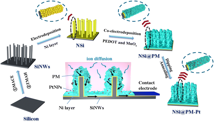
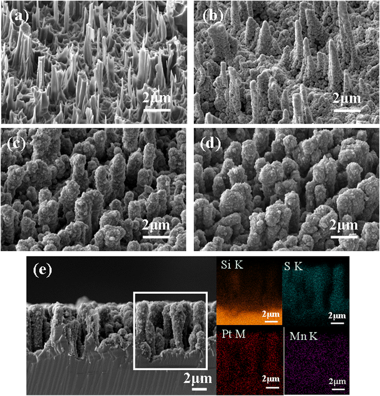
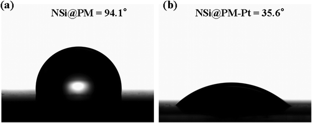
Scheme 1 illustrates the preparation process of the NSi@PM–Pt electrodes. Initially, SiNWs were obtained via a facile two-step process, where the cleaned silicon wafer was etched by the MACE method and then treated with the TMAH solution. Subsequently, Ni particles were decorated around SiNWs (NSi) via the in situ electrodeposition method. To form the core–shell structure of NSi@PM, PMs were co-electrodeposited by using the NSi samples as the framework. Finally, NSi@PM–Pt was prepared by immersing NSi@PM in the ethanol solution of H2PtCl6 and annealing it in vacuum. In our electrode, SiNWs provide a large surface area for loading more active materials of PM. The compact hybrid layers generated from PM and Ni particles could passivate the silicon surface and prevent it from air/electrolyte corrosion. Due to the high conductivity, the Ni layer generated from the Ni particles could be worked as the CC-layer in our electrode. Therefore, the electrodes can be prepared using any type of silicon wafer without needing to consider its conductivity and purity, largely decreasing the cost of the silicon wafer.The representative SEM images of SiNWs, NSi, NSi@PM and NSi@PM–Pt are shown in Fig. 1. It can be observed that vertical nanowire arrays with large gaps are prepared on the silicon wafer (Fig. 1a). The length of SiNWs is ∼6 μm (Fig. S1, ESI†). After electrodeposition, Ni particles were homogeneously wrapped around SiNWs, connecting with each other and forming a CC-layer (Fig. 1b). Moreover, PM particles are tightly coated on NSi (Fig. 1c), resulting in a core–shell structure of NSi@PM with the close contact between the current collector (NSi) and active materials (PM). Interestingly, after modifying with PtNPs, the morphology of NSi@PM–Pt (Fig. 1d) exhibits slight changes compared to that of NSi@PM, although the corresponding EDS mappings illustrate that the Pt element homogeneously appears in the whole surface area of NSi@PM–Pt (Fig. 1e). Additionally, as shown in Fig. 2, the contact angles of NSi@PM and NSi@PM–Pt are 94.1° and 35.6°, respectively. The different contact angles suggest that the surface property of the electrode is changed after PtNPs decoration. The decreased contact angle of NSi@PM–Pt demonstrates that the surface of NSi@PM–Pt is more hydrophilic, which is conducive to the fast ion/electrolyte penetration. Both the EDS mappings and the contact angle test results reveal that PtNPs were successfully synthesized around NSi@PM. The TEM image of NSi@PM–Pt is illustrated in Fig. S2 (ESI†), which further confirms that the Ni particles and PM are uniformly deposited around the nanowires and formed a compact core–shell structure of NSi@PM–Pt. It is known that the silicon surface is easily corroded/oxidized in the electrolyte. Here, the compact composite layers resulting from the PM and Ni particles could physically prevent the contact between the SiNWs and electrolyte, greatly improving the stability of SiNWs, as well as the corresponding synthesized electrodes. However, the PtNPs still cannot be observed. The reason can be ascribed to the tiny size of the PtNPs.
To further study the structure and the composition of the samples, a series of characterizations were carried out. For comparison, the NSi@P sample was also prepared. Fig. 3a presents the Raman spectra of the NSi, NSi@P and NSi@PM composites. Due to the decoration of the highly magnetic Ni particles, there is no characteristic peak in the Raman spectrum of NSi. As observed in the NSi@P spectrum, the peak at 575 cm−1 is assigned to the C–O–C bond deformation, while the bands at 699 cm−1 and 857 cm−1 are associated with the C–S–C bond stretching.32 The peaks at 990 cm−1 and 1256 cm−1 are attributed to the oxyethylene ring deformation and thiophene C–C inter-ring stretching in-plane modes, respectively.33 Additionally, the observed peaks at 1367, 1424 and 1507 cm−1 correspond to the C–C stretching in-plane mode. All of the peaks indicate that PEDOT was successfully prepared around NSi by the electrodeposition method. In addition to these characteristic peaks of PEDOT, the band located at 520 cm−1 in NSi@PM is close to that of a cryptomelane-type MnO2.34Fig. 3b depicts the XRD patterns of the NSi, NSi@P and NSi@PM composites. NSi has a pair of strong Ni characteristic peaks at 44° and 55° (PDF#04-0850), and no other impurity peaks are observed, which indicates that a single metal Ni layer is successfully prepared on the surface of SiNWs. The NSi@P composite has a broad peak around 25°, indicating the amorphous nature of the synthesized PEDOT. Moreover, the decreased intensity of the Ni characteristic peaks in NSi@P also proved that PEDOT was coated on the surface of NSi.35 In addition to the above peaks, the characteristic peaks at 32° and 38° in the XRD line of the NSi@PM composite, which correspond to the (222) and (400) planes of Mn2O3 (PDF#24-0508), respectively, can also be observed. The elemental composition and chemical state of the NSi@PM composite electrode were characterized by X-ray photoelectron spectroscopy (XPS). The presence of S, O, C and Mn elements in the survey spectrum verify the co-existence of PEDOT and MnOX in the composite (Fig. 3c). The Mn 2p signal was analyzed by XPS high-resolution spectrum, where the characteristic peaks at 653.7 and 642.1 eV correspond to Mn 2p1/2 and Mn 2p3/2, respectively (Fig. 3d). The two main peaks of Mn 2p1/2 and Mn 2p3/2 exhibit a spin-energy separation of 11.6 eV, which is consistent with previous literature reports.36,37 All of the XRD, Roman and XPS results indicate that PEDOT and MnOX were successfully synthesized.
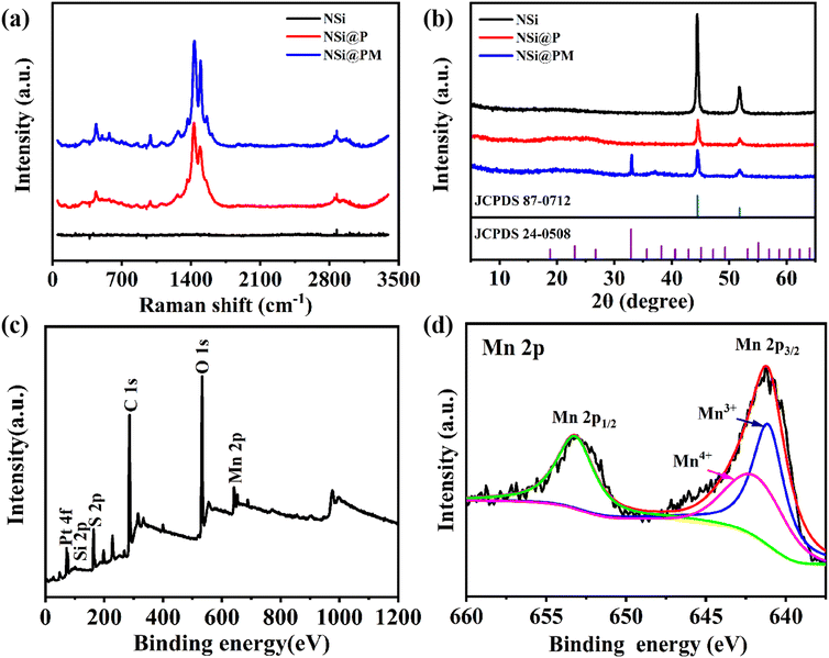 | ||
| Fig. 3 (a) Raman spectra and (b) XRD patterns of NSi, NSi@P and NSi@PM. (c) X-ray photoelectron spectroscopy (XPS) survey spectrum and (d) Mn 2p spectra for NSi@PM composites. | ||
The results presented in this section verify that Ni particles can form the continuous layer around SiNWs, which can act as the 3D current collector of the electrode, and that the composite of PM can be successfully synthesized around NSi by the co-electrodeposition method. The compact composite layer of PM and Ni particles generates a close core–shell structure of NSi@PM, which could prevent SiNWs from corrosion and oxidation in the electrolyte. Moreover, due to the high surface area of SiNWs with large gaps, the synthesized electrode still can retain the 3D core–shell structure of the CC-layer and active materials, affording a lot of active sites and large contact area with the electrolyte.
Electrochemical investigation
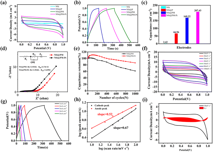
The electrochemical properties of the samples were analyzed in a three-electrode cell with 1 M Na2SO4 solution. Initially, the influence of the deposition time of Ni particles on the electrochemical performance of the NSi@PM electrodes was investigated. As shown in Fig. S3a (ESI†), for the same deposition time of PM, along with the increased deposition time of the Ni particles, the sheet resistance (Rs) and charge transfer resistance (Rct) of the electrode decreased. The best electrochemical performance of the electrode is prepared with 12 min of Ni particles (Fig. S3b and c, ESI†), which can attain 123.73 mF cm−2 at 1 mA cm−2. The SEM images of the corresponding framework (NSi) of the electrodes are shown in Fig. S4 (ESI†). As can be seen, the shorter deposition time of the Ni particles generates a porous and discontinuous Ni layer, which could reduce the conductivity of the current layer, resulting in the higher resistance of the electrode.38 On further increasing the deposition time, a thicker Ni layer is formed around SiNWs, which could decrease the surface area of the active materials and reduce the contact area between the active material and electrolyte, lowing the electrochemical performance of the electrode. Subsequently, the optimized deposition time of the active materials of PM was also investigated. Increasing the deposition time would result in a high mass-loading of PM, but it would also have an adverse effect on increasing the ion/charge transfer resistance. As shown in Fig. S5 (ESI†), the optimized deposition time of PM for NSi@PM is 20 min. According to the above results, NSi@PM with the optimized electrochemical performance was prepared with the deposition times of 12 and 20 min for the Ni layer and PM, respectively.Fig. 4a and b compare the electrochemical performance of NSi, NSi@P, NSi@PM and NSi@PM–Pt with the optimized deposition time of 12 min for the Ni particle and 20 min for the active materials. The corresponding calculated areal capacitance values of these samples at 1 mA cm−2 are shown in Fig. 4c, which are 2.42, 66.96, 169.22 and 207.43 mF cm−2 for NSi, NSi@P, NSi@PM and NSi@PM–Pt, respectively. Comparing the areal capacitance value of NSi with those of other electrodes decorated with active materials, the much smaller value of NSi demonstrates that the substrate of NSi has a slight contribution to the capacity. Thus, we conclude that the primary effect of NSi is to serve as the framework to provide a larger surface area for loading more active materials, and to work as the built-in 3D CC-layer for the electrode. After incorporation with MnOx, the areal capacitance of the electrode largely improved from 66.96 mF cm−2 of NSi@P to 169.22 mF cm−2 of NSi@PM. Obviously, the NSi@PM–Pt electrode displays the highest areal acceptance value, which is 207.43 mF cm−2 at 1 mA cm−2. Decorating active materials with metal nanoparticles could enhance the conductivity of the electrode. Here, after modifying with PtNPs, as shown in Fig. 3, the surface of NSi@PM became more hydrophilic, benefiting the fast ion diffusion during the electrode.38 Both of them contribute to the higher capacitance value of NSi@PM–Pt compared to that of NSi@PM.34 To gain more information about the electrochemical kinetics, EIS measurements were performed and the Nyquist curves are presented in Fig. 4d. Both curves displayed a semicircle in a high-frequency region representing the charge-transfer resistance (Rct) and a straight line in a low-frequency region associated with the diffusion-limited process. Apparently, the line slope of NSi@PM–Pt was larger than that of NSi@PM, signifying its faster ion diffusion ability. Due to the increased conductivity and more hydrophilic surface, the fitted Rct and Rs values for NSi@PM–Pt were much smaller than those of NSi@PM, indicating that the Pt particles decoration could decrease the ion diffusion resistance and improve the electron transport capacity of the electrode. Moreover, as shown in Fig. 4e, after 1000 cycles at 100 mV s−1, NSi@PM–Pt still could retain 87% of the initial capacitance value, much larger than 60% of NSi@PM. The electrode with PtNPs decoration (NSi@PM–Pt) exhibits higher electrochemical performances, such as increased capacitance value, reduced Rs, and improved stability, than those of the electrode without PtNPs (NSi@PM). The result is consistent with previous reports.39–41
Fig. 4f shows the CV curves of NSi@PM–Pt at the scan rates ranging from 10 to 100 mV s−1. It can be observed that all of these curves demonstrate an almost rectangular shape even at the high scan rate of 100 mV s−1, and that the current density increases along the increased scan rates, suggesting the fast ion penetration of the electrolyte during the active materials and excellent conductivity of the electrode. Fig. 4g displays the GCD curves of NSi@PM–Pt at various current densities from 1 to 5 mA cm−2. All of the GCD curves present approximate symmetric triangles with small IR drops. At 5 mA cm−2, the electrode still can achieve an areal capacitance value of 125 mF cm−2, indicating excellent reversibility of the electrode. The capacitive behavior of the electrode is analyzed by the power law:
| i = aνb | (4) |
| i = k1ν + k2ν1/2 | (5) |
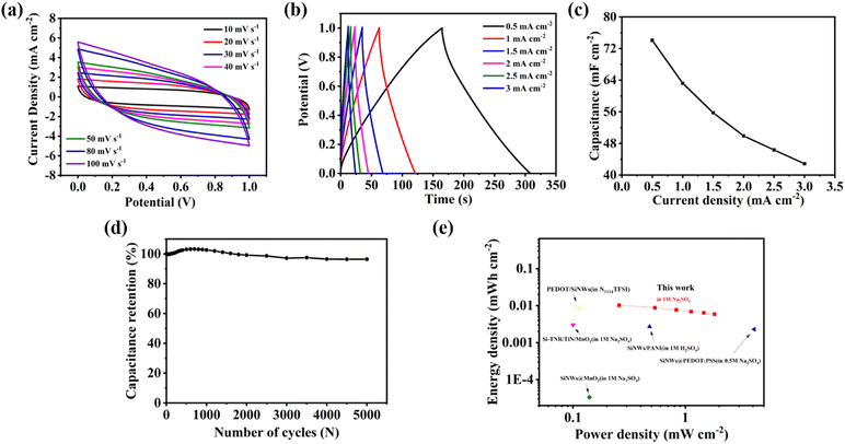
To further confirm the practical application value of the NSi@PM–Pt electrode, we assembled a symmetric supercapacitor (SSC) with NSi@PM–Pt as the electrodes in the electrolyte containing 1 M Na2SO4. Fig. 5a and b presents the CV at the different scan rates and GCD curves at various current densities of the SSC. It can be seen that all of the CV curves maintain a quasi-symmetric shape and all GCD curves show a typical isosceles triangle in shape, indicating the good electrochemical reversibility of SSC. As shown in Fig. 5c, the areal capacitance of the SSC was 74.07 mF cm−2 at 0.5 mA cm−2, which was reduced to 42.88 mF cm−2 at 3 mA cm−2. These values are much higher than those of other reported SSCs prepared with silicon-based electrodes, such as SiNWs/MnO2 (2.21 mF cm−2 at 0.04 mA cm−2),43 SiNWs/PEDOT@PPy (46.05 mF cm−2 at 0.5 mA cm−2),44 SiNWs/D/PEDOT (9.5 mF cm−2 at 0.1 mA cm−2),45 and Si/PM/rGO-PsAg (24.7 mF cm−2 at 0.1 mA cm−2).39 The lifetime is important for the practical SCs. As shown in Fig. 5d, after 5000 cycles, there is only ∼5% degradation in the capacitance for the device, suggesting that NSi@PM–Pt is a highly stable electrode for SCs. According to the Ragone plot in Fig. 5e, the device exhibits energy and power energy densities ranging from 0.006 to 0.0103 mW cm−2 and 0.2503 to 1.5115 mW h cm−2, respectively.
Conclusions
In summary, a large surface area of NSi was prepared with a simple and cost-effective solution method, where Ni particles connected with each other, generating a highly conductive layer. PM can be successfully deposited around NSi by the one-step co-electrodeposition method. The composite layer generated from PM and Ni particles could prevent silicon from oxidation/corrosion, largely improving the stability of SiNWs and the electrode. After decoration with Pt NPs, the conductivity of the electrode was improved and the surface became more hydrophilic. After optimization, the prepared NSi@PM–Pt electrode demonstrated a high areal specific capacitance of 207.43 mF cm−2 at 1 mA cm−2. The symmetric device delivered a maximum energy density of 0.006 mW cm−2 with good stability retention of up to 94.6% over 5000 cycles. The results afford a promising solution strategy to prepare high-performance silicon-based SCs with a simple, facile and cost-effective method.Author contributions
Xiaojuan Shen and Maiyong Zhu conceived and designed the experiments; Penwei Liu performed the experiments and wrote the paper; Shouyan Sun and Tongfei Wang contributed to formal analysis.Conflicts of interest
There are no conflicts to declare.References
- Q. Zhu, D. Zhao, M. Cheng, J. Zhou, K. A. Owusu, L. Mai and Y. Yu, A new view of supercapacitors: integrated supercapacitors, Advanced Energy, Materials, 2019, 9, 1901081 Search PubMed.
- N. Wu, X. Bai, D. Pan, B. Dong, R. Wei, N. Naik, R. R. Patil and Z. Guo, Recent advances of asymmetric supercapacitors, Adv. Mater. Interfaces, 2021, 8, 2001710 CrossRef CAS.
- D. P. Chatterjee and A. K. Nandi, A review on the recent advances in hybrid supercapacitors, J. Mater. Chem. A, 2021, 9, 15880–15918 RSC.
- L. Liu, H. Zhao and Y. Lei, Advances on three-dimensional electrodes for micro-supercapacitors, InfoMat, 2019, 1, 74–84 CrossRef CAS.
- Y. Z. Tetard, L. Zhai and L. Thomas, Supercapacitor electrode materials: nanostructures from 0 to 3 dimensions, Energy Environ. Sci., 2015, 8, 702–730 RSC.
- Q. Zhu, D. Zhao, M. Cheng, J. Zhou, K. A. Owusu, L. Mai and Y. Yu, A new view of supercapacitors: integrated supercapacitors, Advanced Energy, Materials, 2019, 9, 1901081 Search PubMed.
- N. Wu, X. Bai, D. Pan, B. Dong, R. Wei, N. Naik, R. R. Patil and Z. Guo, Recent advances of asymmetric supercapacitors, Adv. Mater. Interfaces, 2021, 8, 2001710 CrossRef CAS.
- D. P. Chatterjee and A. K. Nandi, A review on the recent advances in hybrid supercapacitors, J. Mater. Chem. A, 2021, 9, 15880–15918 RSC.
- P. Y. Yao, Z. Li, J. C. Zhu, X. X. Ran, Z. C. Shi and J. L. Zhu, Controllable synthesis of NiCo-LDH/Co(OH)2@PPY composite via electrodeposition at high deposition voltages for high-performance supercapacitors, J. Alloys Compd., 2021, 875, 160042 CrossRef CAS.
- Nilesh R. Chodankar, Indrajit V. Bagal, Sang-Wan Ryu and Do-Heyoung Kim, Hybrid material passivation approach to stabilize the silicon nanowires in aqueous electrolyte for high-energy efficient supercapacitor, Chem. Eng. J., 2019, 362, 609–618 CrossRef CAS.
- X. X. Li, X. H. Deng, Q. J. Li, S. Huang, K. ao, Z. Q. Liu and Y. Tong, Hierarchical double-shelled poly (3, 4-ethylenedioxythiophene) and MnO2 decorated Ni nanotube arrays for durable and enhanced energy storage in supercapacitors, Electrochim. Acta, 2018, 264, 46–52 CrossRef CAS.
- Y. Ding, Z. Q. Wang, X. L. Duan and R. Y. Liu, Flexible photo-charging power sources for wearable electronics, Materials Today, Energy, 2023, 33, 101276 Search PubMed.
- M. Y. Lin, H. J. Hu, S. Zhou and S. Xu, Soft wearable devices for deep-tissue sensing, Nature Review, Materials, 2022, 7, 870 Search PubMed.
- Z. Li, F. Wang and X. Wang, Hierarchical branched vanadium oxide nanorod@ Si nanowire architecture for high performance supercapacitors, Small, 2017, 13, 1603076 CrossRef PubMed.
- B. B. Shao, C. F. Xing and Y. H. Song, Boosting electrical output of nanostructured silicon hydrovoltaic device via cobalt oxide enabled electrode surface contact, Nano Energy, 2023, 106, 108081 CrossRef CAS.
- D. Sadki. Aradilla and S. G. Bidan, Beyond conventional supercapacitors: Hierarchically conducting polymer-coated 3D nanostructures for integrated on-chip micro-supercapacitors employing ionic liquid electrolytes, Synth. Met., 2019, 247, 131–143 CrossRef.
- C. Y. Zhang, M. X. Wang and C. H. Jiang, Highly adhesive and self-healing γ-PGA/PEDOT:PSS conductive hydrogels enabled by multiple hydrogen bonding for wearable electronics, Nano Energy, 2022, 95, 106991 CrossRef CAS.
- R. Y. Liu, J. Wang and T. Sun, Silicon Nanowire/Polymer Hybrid Solar Cell-Supercapacitor: A Self-Charging Power Unit with a Total Efficiency of 10.5%, Nano Lett., 2017, 17, 4240–4247 CrossRef CAS PubMed.
- D. R. Reddy, S. Sabine, C. Yannick and B. Rabah, Glucose-Derived Porous Carbon-Coated Silicon Nanowires as Efficient Electrodes for Aqueous Micro-Supercapacitors, ACS Appl. Mater. Interfaces, 2016, 8, 4298–4302 CrossRef PubMed.
- T. Lé, P. Gentile, G. Bidan and D. Aradilla, New electrolyte mixture of propylene carbonate and butyltrimethylammonium bis (trifluoromethylsulfonyl) imide (N1114 TFSI) for high performance silicon nanowire (SiNW)-based supercapacitor applications, Electrochim. Acta, 2017, 254, 368–374 CrossRef.
- D. Aradilla, D. Gaboriau, G. Bidan, P. Gentile, M. Boniface, D. Dubal and S. Sadki, An innovative 3-D nanoforest heterostructure made of polypyrrole coated silicon nanotrees for new high performance hybrid micro-supercapacitors, J. Mater. Chem. A, 2015, 3, 13978–13985 RSC.
- X. Shen, C. Liu, X. Zhang, J. Li and S. Zhao, High capacitive PEDOT-coated SiNWs electrode for micro-supercapacitors with facile preparation, J. Inorg. Organomet. Polym. Mater., 2020, 30, 3722–3734 CrossRef CAS.
- S. Hussain, R. Amade, A. Boyd, A. Musheghyan-Avetisyan, I. Alshaikh, J. Martí-Gonzalez and E. Bertran-Serra, Three-dimensional Si/vertically oriented graphene nanowalls composite for supercapacitor applications, Ceram. Int., 2021, 47, 21751–21758 CrossRef CAS.
- T. H. Wu, C. T. Chang, C. C. Wang, S. Parwaiz, C. C. Lai, Y. Z. Chen and Y. L. Chueh, Few-layer graphene sheet-passivated porous silicon toward excellent electrochemical double-layer supercapacitor electrode, Nanoscale Res. Lett., 2018, 13, 1–9 CrossRef CAS PubMed.
- B. Wei, H. Liang, Q. Z. Zhang, D. Shen, H. Hu and W. Wang, Construction of 3D Si@Ti@TiN thin film arrays for aqueous symmetric supercapacitors, Chem. Commun., 2019, 55, 1402–1405 RSC.
- B. Zhu, X. Wu, W. J. Liu, H. L. Lu, D. W. Zhang, Z. Fan and S. J. Ding, High-performance on-chip supercapacitors based on mesoporous silicon coated with ultrathin atomic layer-deposited In2O3 films, ACS Appl. Mater. Interfaces, 2018, 11, 747–752 CrossRef PubMed.
- X. Shen, X. Wei, T. Wang, S. Li and H. Li, Solution-processable hierarchical SiNW/PEDOT/MnOx electrodes for high-performance supercapacitors, Mater. Chem. Front., 2022, 6, 2894–2904 RSC.
- X. Shen, X. Wei, T. Wang and S. Li, Facile synthesis of metal oxide and conductive polymers around silicon nanowire arrays for a high-performance aqueous supercapacitor, ACS Appl. Energy Mater., 2022, 5, 2596–2605 CrossRef CAS.
- X. Zhang, T. Wang, S. Li and X. Shen, Electrodeposition polyaniline nanofiber on the PEDOT: PSS-coated SiNWs for high performance supercapacitors, J. Inorg. Organomet. Polym. Mater., 2021, 31, 4260–4271 CrossRef CAS.
- X. Shen, X. Zhang and T. Wang, et al., A novel 3D porous electrode of polyaniline and PEDOT: PSS coated SiNWs for low-cost and high-performance supercapacitors, Mater. Chem. Front., 2021, 5, 6114–6124 RSC.
- G. A. Bowmaker, W. W. Chiu, R. P. Cooney and J. Trava-Sejdi, Studies of dopant effects in poly(3,4-ethylenedi-oxythiophene) using Raman spectroscopy, J. Raman Spectrosc., 2006, 37, 1354–1361 CrossRef.
- T. Gao, M. Glerup, F. Krumeich, R. Nesper, H. Fjellvåg and P. Norby, Microstructures and spectroscopic properties of cryptomelane-type manganese dioxide nanofibers, J. Phys. Chem. C, 2008, 112, 13134–13140 CrossRef CAS.
- M. S. Mulla, A. I. Torvi, L. C. Poulose and M. Y. Kariduraganavar, Development of novel PVA-TEOS-MnO2 and its PANI incorporated flexible membrane electrodes and evaluation of their supercapacitor performance, Electrochim. Acta, 2023, 470, 143260 CrossRef CAS.
- J. Li, E. Fiset, J. Yang, P. Yuan, X. Ling, D. Hulicova-Jurcakova and L. Wang, Formation of graphitic tubules from ordered mesoporous carbon and their effect on supercapacitive energy storage, J. Mater. Chem., 2012, 22, 21472–21480 RSC.
- A. H. Feng, J. Wang, H. Lai and M. Lu, MnO2 nanotube and nanowire arrays by electrochemical deposition for supercapacitors, J. Power Sources, 2010, 195, 4410–4413 CrossRef.
- X. Shen, X. Wei, T. Wang, S. Li and H. Li, Polypyrrole embedded in nickel-cobalt sulfide nanosheets grown on nickel particles passivated silicon nanowire arrays for high-performance supercapacitors, Chem. Eng. J., 2023, 461, 141745 CrossRef CAS.
- R. Sha and S. Badhulika, Binder free platinum nanoparticles decorated graphene-polyaniline composite film for high performance supercapacitor application, Electrochim. Acta, 2017, 251, 505–512 CrossRef CAS.
- X. Guo, T. Wang, T. X. Zheng, C. Xu, J. Zhang, Y. X. Zhang and F. Dong, Quasi-parallel arrays with a 2D-on-2D structure for electrochemical supercapacitors, J. Mater. Chem. A, 2018, 6, 24717–24727 RSC.
- A. Soam, K. Parida, R. Kumar and R. O. Dusane, Silicon-MnO2 core-shell nanowires as electrodes for micro-supercapacitor application, Ceram. Int., 2019, 45, 18914–18923 CrossRef CAS.
- J. Wang, Y. Guan, Q. Zhang, H. Zhu, X. Li, Y. Li and Y. Cong, Well-dispersed ultrafine Pt nanoparticles anchored on oxygen-rich surface of V2CTx (MXene) for boosting hydrogen evolution reaction, Appl. Surf. Sci., 2022, 582, 152481 CrossRef CAS.
- L. Que, L. Zhang, C. Wu, Y. Zhang, C. Pei and F. Nie, Pt-decorated graphene network materials for supercapacitors with enhanced power density, Carbon, 2019, 145, 281–289 CrossRef CAS.
- X. Guo. Wang, T. X. Zheng, C. Xu, J. Zhang, Y. X. Zhang and F. Dong, Quasi-parallel arrays with a 2D-on-2D structure for electrochemical supercapacitors, J. Mater. Chem. A, 2018, 6, 24717–24727 RSC.
- A. Soam, K. Parida, R. Kumar and R. O. Dusane, Silicon-MnO2 core-shell nanowires as electrodes for micro-supercapacitor application, Ceram. Int., 2019, 45, 18914–18923 CrossRef CAS.
- Q. Zhou, Y. Zhou, M. Bao and X. Ni, Modified silicon nanowires@ polypyrrole core-shell nanostructures by poly(3,4-ethylenedioxythiophene) for high performance on-chip micro-supercapacitors, Appl. Surf. Sci., 2019, 487, 236–243 CrossRef CAS.
- D. Aradilla, F. Gao, G. Lewes-Malandrakis, W. Müller-Sebert, P. Gentile and M. Bidan, Boniface, GDesigning 3D multihierarchical heteronanostructures for high-performance on-chip hybrid supercapacitors: poly(3,4-(ethylenedioxy) thiophene)-coated diamond/silicon nanowire electrodes in an aprotic ionic liquid, ACS Appl. Mater. Interfaces, 2016, 8, 18069–18077 CrossRef CAS PubMed.
Footnote |
| † Electronic supplementary information (ESI) available. See DOI: https://doi.org/10.1039/d3ya00594a |
| This journal is © The Royal Society of Chemistry 2024 |

