 Open Access Article
Creative Commons Attribution 3.0 Unported Licence
Redox reaction by thermal excitation carriers in semiconductors: semiconductor-sensitized thermal cell
Sachiko
Matsushita
 ab
ab
aDepartment of Materials Science and Engineering, Institute of Science Tokyo, J2Bldg. 1410, 4259 Nagatsuta, Midori-ku, Kanagawa 226-8503, Japan. E-mail: matsushita.s.ab@m.titech.ac.jp
belleThermo, Ltd, INDEST 3F, Institute of Science Tokyo, Shibaura 3-3-6, Minato-ku, Tokyo 108-0023, Japan
First published on 11th March 2025
Abstract
The semiconductor-sensitized thermal cell (STC) is a groundbreaking thermal energy conversion technology capable of converting low-temperature heat (<200 °C) directly into electricity. It is based on the concept of a dye-sensitized solar cell (DSSC), but instead of photoexcited carriers in a dye, STC depends on the redox reaction of electrolyte ions initiated by thermally excited carriers in a semiconductor. One of the most appealing features of an STC is that once it reaches discharge termination, power generation can be restored by turning off the switch and leaving the STC in the heat source. This paper is the first comprehensive review in English of STCs, which have previously been used to enable Bluetooth communication with asphalt heat and to charge lithium-ion batteries with geothermal heat in Mexico.
Introduction
Heat is often regarded as “low-quality” energy. However, when the sun stops generating heat in 4 billion years, Earth will become extremely cold and human beings will become extinct—unless science and technology advance or humans evolve. In other words, heat is an enormous energy source that can sustain life.When we examine the density of various forms of environmental energy around us (Table 1), we find that heat has large energy density.
| Energy type | Energy density |
|---|---|
| a For vibration power generation, frequency-dependent energy density is described because power cannot be extracted unless the frequency of shaking in the installation environment of the device matches the resonant frequency of the device. | |
| Light (outside) | 100 mW cm−2 |
| Light (inside) | 100 μW cm−2 |
| Vibrationa (machine) | 1 G@50 kHz |
| Vibrationa (human) | 0.1 G@1 kHz |
| Heat (machine) | 100 mW cm−2 |
| Heat (human) | 20 mW cm−2 |
| Electromagnetic wave (mobile phone) | ∼0.3 μW cm−2 |
Geothermal power generation1,2 and Seebeck thermoelectricity3–5 are popular technologies that use thermal energy to generate power. Geothermal power generation requires detecting a heat source and mining to confirm a water source in the preliminary investigation stage. Although a heat source can be accurately detected in the preliminary investigation, the presence of a sufficient water source to turn the turbine remains uncertain until mining is performed, resulting in unnecessary expenditures. Primarily, the number of countries with abundant water sources is limited, making this technology difficult to implement. In the Seebeck-type power generation method, voltage is generated due to the difference in the number of electric charges generated in semiconductors and metals exposed to high and low temperatures. This method relies on a temperature gradient, which complicates the module. Therefore, in Seebeck-type thermoelectricity, it is not possible to obtain electricity by fully embedding the device in a heat source.
Extracting electricity directly from a heat source at a constant temperature will have promising applications in electronic equipment, geothermal energy systems, as well as on the human body. This would complement the applications of Seebeck-type thermoelectricity, such as recovery of waste heat in factories, the utilization of heat from automobile exhaust gases, and space exploration.
Non-equilibrium thermodynamics
The method of extracting electricity directly from a heat source at a constant temperature is considered a Type 2 perpetual motion engine. A Type 2 perpetual motion engine a hypothetical device that operates by performing work using the heat supplied, generating heat from the work done, and continues to work indefinitely by reusing the heat generated. This process repeats in a closed system with a thermal energy conversion efficiency of 100%.In fact, this Type 2 perpetual motion engine, troublingly, is not disproven. Even more troubling is the fact that many people in science have only studied thermodynamics, which is a closed system.
Let us consider about our skin for a moment. Your skin acts as a barrier that separates your body from external environment. Why was that skin(barrier) formed? Is the formation of that skin consistent with the law of increasing entropy?
Yes. It is—when the skin can no longer retain its shape; that is, after death. After death, the skin of everyone reading this will become sloppy, if left unattended. It will ultimately decompose, confirming the law of increasing entropy.
Does living contradict the law of increasing entropy? No. You eat and drink to live. You are breaking up water and food, thereby increasing the entropy elsewhere. This increase in entropy continues as long as we live. That is why we are alive (except when we are nourished and wastes in our body are expelled, externally by the intervention of medical science).
This academic theory that states that form is born and can be maintained in the entropy flow is called the theory of dissipative structure,6,7 constructed by Dr Ilya Prigogine,8 who was awarded the Nobel Prize in Chemistry in 1977.9 It is also called non-equilibrium thermodynamics10,11 or the thermodynamics of open systems.12,13
From this point onward, we will introduce the concept of power generation at isothermal temperatures. However, it is crucial to note that there is a continuous flow of energy, which should be discussed in the thermodynamics of open systems as is the case with other renewable energy sources. For example, a wind turbine is an open system that rotates because of the wind. Solar cells are open systems that generate electricity because of light, and Seebeck-type thermoelectricity is an open system that produces electricity because of heat flow.
Fundamentally, it is defined that entropy increases if electricity is flowing.
Power generation at isothermal temperature
In recent years, numerous isothermal power generation technologies have been introduced one after another. Far-infrared solar cells, which generate electricity by harnessing radiant heat (that exists as electromagnetic waves), similar to solar cells, have existed for a long time. However, in recent years, there have been numerous new technologies, particularly those involving the term “thermophotovoltaic energy conversion”,14–16 plasmon-induced infrared power generation,17 near-field thermophotovoltaic devices that effectively utilize the wavelength selectivity of photonic crystals18,19 and other advancements.A metamaterial is placed on one side of a Seebeck-type thermoelectric element to absorb thermal radiation, resulting in a temperature gradient in the thermoelectric element to generate electricity.20 Organic molecular thermoelectricity depends on charge separation at organic donor/acceptor interfaces.21 A tertiary battery22,23 generates electricity by taking advantage of temperature fluctuations in the installation environment. Electricity can be generated through electron hopping in a nanoparticle fluid at high temperatures.24 Another example is the semiconductor-sensitized thermal cell introduced in this paper. Several other power generating principles await further study, such as an open circuit voltage has been reported without any corresponding discharge current.25,26 The temperature and maximum power generation of each are plotted in Fig. 1, which gives insights into the progress toward direct thermal power generation.
From dye-sensitized solar cell to semiconductor-sensitized thermal cell
Let us take a short break from thermal power generation and introduce a chemical-based solar cell called a dye-sensitized solar cell (DSSC).27,28 This solar cell, commonly called as “Grätzel cell,” was proposed in 1991 by Michael Grätzel et al. at the Lausanne University of Technology in Switzerland. The Grätzel solar cell is thin, light in weight and has a high efficiency. It can be red or green in color. It has a simple structure consisting of three parts: a working electrode covered with dyes, a counter electrode, and an electrolyte and is used in science experiments for elementary school students.In a DSSC, electrons in the dye on the working electrode are excited by light. The excited electrons move to the electron transport layer to which the dye is attached (the combination of the dye and electron transport layer serves as the working electrode) and then to the counter electrode. The electrons reduce electrolyte ions at the counter electrode/electrolyte interface. The reduced electrolyte ions are oxidized by the holes remaining in the dye. In this way, excited electrons move between the working electrode, counter electrode, and electrolyte, generating an electric current. Quantum-dot-sensitized solar cells that use inorganic quantum dots instead of organic dyes that tend to degrade, have also been reported.29
If the photoexcitation of the dye is replaced with thermal excitation of the semiconductor, the excited electrons will probably move through the working electrode, counter electrode, and electrolyte in the same way. In other words, electricity can be generated when heat is applied (Fig. 2). The effect of excited carriers on the redox reaction is identical, whether they are photoexcited or thermally excited. In both scenarios, the energy levels of carriers remain unchanged when transferred to the electron transport material. The electron does not retain any memory of whether it was excited by light or heat.
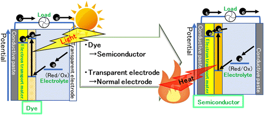 | ||
| Fig. 2 Schematic image of a dye-sensitized solar cell and a semiconductor-sensitized thermal cell. Mater.: material. | ||
Thermal excitation carriers in semiconductors
Heat is often considered a small, poor-quality energy compared to light, and that it cannot produce large amounts of energy. Indeed, at room temperature, air molecules have a kinetic energy of only 0.038 eV. However, when a semiconductor is heated, the atoms that compose the bands vibrate in the lattice, generating thermal excitation carriers with energy corresponding to the band30 (Fig. 3). As the position of the band depends on the arrangement of the atoms, the potential of the carriers is independent of the magnitude of the thermal energy. In fact, Mizuguchi et al. reported that polycarbonate is oxidized by thermally excited holes in the valence band of titanium dioxide, a well-known photocatalyst.31The number of thermal excitation carriers in a semiconductor follows the Fermi–Dirac equation. For example, 2.4 × 10¹³ carriers are generated in a 1 cm3 Ge semiconductor at 80 °C, which is more than the number of photons, 4 × 1011 cm−2 (calculated as 555 nm monochromatic light) at 1 lux in a room. Furthermore, the number of excited carriers is comparable to that of a solar cell because, unlike light excitation, which occurs at the irradiation “surface,” thermal excitation spreads through the entire “body” via thermal conduction.
In summary, both thermal and light excitation have a sufficient number of excited carriers, and when the carriers move within the material after excitation, they are in the same state. Oxidation by thermally excited holes has also been confirmed. Then in the DSSC system, the redox reaction is possible using the thermal excitation carriers of the semiconductor instead of the light excitation carriers of the dye; i.e., electricity can be generated by heat. We named this new thermal energy conversion technology a “semiconductor-sensitized thermal cell (STC),” inspired by dye-sensitized solar cells. We did not call it a thermal cell to prevent confusion with a thermoelectrochemical cells.32,33
Proof of concept of STC
Redox reaction by thermal excitation carriers
A semiconductor with many thermal excitation carriers n is suitable for STC. Here, n can be defined using energy bandgap width Eg, temperature T, density of states at conduction and valence bands, Nc, Nv, respectively, given by the following equation:Here, Eg is neither too large nor too small. A too large energy band gap, Eg leads to lower n and too small Eg leads to lower acquisition voltage when made in an STC.
The first semiconductor chosen for STCs was β-FeSi2, which garnered attention as a thermoelectric material in 2015. It has a band gap of 0.7 eV, making it suitable for using heat below 200 °C. It does not use rare metals, giving it a material cost advantage. For the electron transport layer, n-Si was selected, which is often used in combination with β-FeSi2 as a light-emitting device. Copper ions were selected as electrolyte ions because their redox potential is almost same with that of the valence band of β-FeSi2. A solid electrolyte, the Cu-ion super conductor called CUSICON, was selected as the copper ion conductor.
The long-term power generation by the STC was confirmed at 600 °C, where Cu-ion conduction occurs in the CUSICON, under an air atmosphere and N2 gas. X-ray photoelectron spectroscopy (XPS) analysis of the CUSICON interface in contact with the working electrode and the counter electrode, respectively, after long-term discharge showed oxidation of copper ions on the working electrode side and reduction of copper ions on the counter electrode side. In other words, it was confirmed that the redox reaction of ions can be induced by thermal excitation carriers; this was the first study on STC.34 The higher purity of β-FeSi2 gave better electric power generation.35
Later, in an STC using germanium as the semiconductor and a polymer containing copper ions as the electrolyte, it was observed that the color of the electrolyte on the semiconductor side oxidizes to brown and the color of the electrolyte on the counter electrode side reduces to white. This was confirmed by tracking the color change before, during, and after discharge, taking advantage of the fact that the divalent copper ion is brown and the monovalent copper ion is white.36
Both light- and heat-excited power generation
After confirming the redox potential of thermally excited carriers, we decided to check whether a semiconductor-sensitized cell could generate electricity either by light or by heat. The semiconductor materials used were organic perovskite (CH3NH3PbI3)37,38 and silver sulfide,39 both semiconductors that have been used in dye-sensitized solar cells.40,41 Thus, power generation was confirmed for both materials, both by light and by heat (Fig. 4).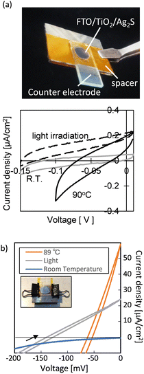 | ||
| Fig. 4 The outlook and cyclic voltammogram of an Ag2S-sensitized thermal cell39 (a) and a perovskite-sensitized thermal cell37 (b) (Copyright © 2019 American Chemical Society). | ||
Furthermore, two major differences were identified.
(1) The open circuit voltage (Voc) in thermal excitation is smaller than that in light excitation.
(2) In light excitation, electricity is generated all the time during light irradiation, but in thermal excitation, electricity generation stops at a certain temperature (even though there is always a heat inflow to keep the temperature at a certain level). After the discharge ends, it can be switched off and left in the heat source to reset, making it ready for discharge again in heat.
The difference in Voc in point (1) is due to the quasi-Fermi level and the Fermi level (Fig. 5). When a semiconductor is exposed to light, more electrons and holes are produced than in thermal equilibrium.42 To describe the behavior of the large amount of photoexcited charge produced, the Fermi level of electrons and holes is set to the quasi-Fermi level. The quasi-Fermi level is lower than the Fermi level, resulting in a smaller open circuit voltage for thermal excitation than that for light excitation. The relationship between the Fermi level and the Voc of STC was carefully examined by adjusting the Fermi level of the entire semiconductor electrode by varying the doping amount of n-Si, which acts as the electron transport layer.43
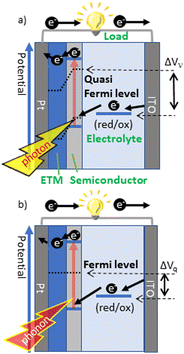 | ||
| Fig. 5 Schematic image of the output potential by (a) photoexcitation and (b) thermal excitation. ETM: electron transport material43 (Copyright © 2020 The Chemical Society of Japan). | ||
Later, STC power generation using CuFeS2 was reported, suggesting its broad applicability.44 The STC power generation temperature was confirmed to be in the range of 20–600 °C, close to the reported temperature of Seebeck thermoelectrics (the cooling part was −100 °C and the heating part was 600 °C). STCs generate electricity even though they are small. The cost of producing output power may be lower than that of Seebeck thermoelectrics, which require a temperature gradient and typically occupy a larger volume. Of course, the STC output relies on the thermal energy density in the space. The most suitable STC applications are in large spaces with abundant heat sources, such as geothermal energy sites, abandoned mines, and data centers.
Power generation recovery
To confirm the long-term discharge behavior of STCs, we needed an electrolyte that can easily transfer ions at relatively low temperatures, has low volatility, and remains stable over long periods. Therefore, we focused on polyelectrolytes, especially polyethylene glycol (PEG)—a well-known, chemically-stable polyelectrolyte solvent. Here, a Ge semiconductor was used. Sealing is very important in Ge–PEG systems as both Ge semiconductors and PEG are denatured by water and oxygen.Fig. 6a shows voltage change behavior during termination and recovery of power generation.45 If the STC is discharged at a certain temperature, the discharge will eventually stop. After the device is turned off and left in the heat source for a while, it will be ready to be discharged again. The longer the switch is turned off, the longer the subsequent discharge time, though it gradually reaches saturation. Fitting analysis indicates that this discharge is not an electric double-layer discharge. In addition, inductively coupled plasma (ICP) elemental analysis of the electrolyte after long-term discharge confirms that this discharge is NOT caused by the dissolution of the semiconductor electrode.
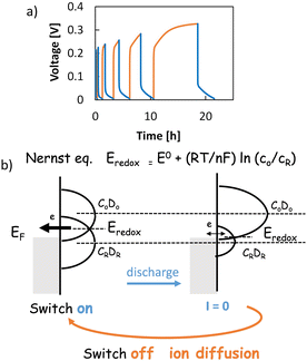 | ||
| Fig. 6 Voltage behaviour of n-Si/Ge/copper ionic electrolyte/FTO at 80 °C, 100 nA discharge and recovery (a);45 conceptual diagram of Nernst's equation (b); blue: discharge (switch on), orange: recovery (switch off). EF: Fermi level. E0: standard redox potential. co, cR: concentration of oxidized and reduced elements. DO, DR: density of states of oxidized and reduced ions (Copyright © 2019 Royal Society of Chemistry). | ||
The discharge terminates for two reasons. (i) There is not enough reactant at the interface. (ii) Equilibrium is reached. We will delve a little deeper into this “equilibrium state at the set temperature.”
When the Fermi level EF of the electrode is different from the redox level Eredox, Eredox becomes equal to EF by Nernst's equation as the reaction proceeds,46 and the acquired current is apparently zero (Fig. 4b, right).
| Eredox = E0 + (RT/nF)ln(co/cR) |
In STC, the equilibrium state A at which the discharge ends is considered to be when Eredox = EF is reached.
This is precisely the difference between light and heat. As mentioned above, in the case of light, there is no cessation of the reaction according to the Nernst equation, because Voc is generated from the quasi-Fermi level of the electrons (macroscopically, it can be understood that light introduces a non-equilibrium state into the system). With heat, however, only Fermi levels are formed. At a constant temperature, the equilibrium state A will be reached at some time and power generation will be terminated.
When turned off, no chemical reaction occurs at the counter electrode interface; at Eredox = EF, many oxidized ions accumulate at the semiconductor electrode/electrolyte interface, and many reduced ions accumulate at the counter electrode/electrolyte interface, resulting in non-uniform ion concentration.
To resolve this non-uniformity, the oxidized and reduced ions diffuse during the switch-off period. Thus, the system moves far from the equilibrium state A and will be ready to be discharged again.
The above is considered to be the principle of the recovery phenomena by switching on and off. This phenomenon was clarified by carefully changing the distance between electrodes and taking into account the ion diffusion length obtained from electrochemical impedance measurements.47 Obviously, the ionic conductivity of the polymer electrolyte plays an essential role in obtaining high currents and reducing the recovery time.
Conclusions
The above gives a brief description of the power generation and recovery behavior of STCs. STCs are often compared to Seebeck thermoelectrics. However, the significant difference is that STCs do not require a temperature gradient at the installation site (although they do need something to create heat flow in the overall system just as wind power requires wind).Recently, a study of STCs using gel electrolytes has been published, and the scope of research is moving from theoretical studies to practical applications.48 In theory, an STC tends to have a large voltage but a small current. Therefore, it is important to increase the specific surface area of the electrode, the ion concentration, and the ionic conductivity. Semiconductors with high thermal excitation charge will be ideal for STCs. For an electrolyte, it is preferable to choose one where the redox reaction occurs smoothly within the electrolyte. An example of this would be the electrolyte used in redox flow batteries. The biggest hurdle to the practical application of STCs is likely to be the soaring price of semiconductors. In this regard, it is necessary to develop inexpensive semiconductors that remain affordable throughout the process, including sourcing raw materials and fabrication scaling from the basic research level to commercial level.
For humans, it makes a big difference whether electricity is generated by light or heat. It is not the energy source that dictates electron movement, but rather the quantity of electrons involved.
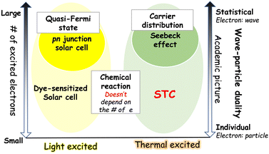
In p–n junction solar cells, a large number of photoexcited carriers is generated, establishing a quasi-Fermi level and resulting in electricity. Seebeck thermoelectrics, which generate electricity from temperature differences, also generate electricity due to the concentration gradient created as a result of high number of electrons. In these cases, electrons can be expressed as a statistic and treated as a wave. On the other hand, DSSCs and STCs generate electricity when there is at least one reactive electron and one reactive substance, respectively. In such chemically reactive power generation, electrons are represented as particles (Fig. 7).
The emergence of STC will help us further explore these four energy conversion technologies: p–n junction solar cells, DSSCs, Seebeck thermoelectrics, and STCs, from the perspective of the “number of excited charges” and will further deepen our understanding of each type of energy conversion.
Data availability
No primary research results, software or code have been included and no new data were generated or analyzed as part of this review.Conflicts of interest
There are no conflicts to declare.Acknowledgements
This work was technically supported by Materials Analysis Division, Core Facility Center, Science Tokyo, Japan; Prof. Akihiro Matsutani, Science Tokyo, Japan; Prof. Takashi Ubukata, Yokohama National University, Japan, and financially supported by JSPS KAKENHI Grant Number 21H02041, Sanoh Co., Tohnic Co., Sakata INX Co. The author expresses sincere thanks to all students and staff members who have developed the STC research.References
- J. W. Lund and A. N. Toth, Geothermics, 2021, 90, 101915 CrossRef.
- R. Rohit, D. C. Kiplangat, R. Veena, R. Jose, A. Pradeepkumar and K. S. Kumar, Renewable Sustainable Energy Rev., 2023, 184, 113531 Search PubMed.
- A. Nozariasbmarz, H. Collins, K. Dsouza, M. H. Polash, M. Hosseini, M. Hyland, J. Liu, A. Malhotra, F. M. Ortiz, F. Mohaddes, V. P. Ramesh, Y. Sargolzaeiaval, N. Snouwaert, M. C. Özturk and D. Vashaee, Appl. Energy, 2020, 258, 114069 Search PubMed.
- T. Matsuo, K. Kawabata and K. Takimiya, Bull. Chem. Soc. Jpn., 2022, 95, 1047–1053 CAS.
- M. Hase, D. Tanisawa, K. Kohashi, R. Kamemura, S. Miyake and M. Takashiri, Sci. Rep., 2023, 13, 13463 CAS.
- I. Prigogine and G. Nicolis, J. Chem. Phys., 1967, 46, 3542–3550 CAS.
- I. Prigogine and R. Lefever, J. Chem. Phys., 1968, 48, 1695–1700 Search PubMed.
- M. Ramage, K. Shipp, M. Ramage and K. Shipp, Syst. Thinkers, 2020, 235–244 Search PubMed.
- I. Procaccia and J. Ross, Science, 1977, 198, 716–717 CAS.
- S. R. De Groot and P. Mazur, Non-equilibrium thermodynamics, Courier Corporation, 2013 Search PubMed.
- D. del Olmo, M. Pavelka and J. Kosek, J. Non-Equilib. Thermodyn., 2021, 46, 91–108 Search PubMed.
- F. Fidaleo and S. Viaggiu, Phys. A, 2017, 468, 677–690 Search PubMed.
- A. Colla and H.-P. Breuer, Phys. Rev. A, 2022, 105, 052216 CrossRef CAS.
- R. Mittapally, A. Majumder, P. Reddy and E. Meyhofer, Phys. Rev. Appl., 2023, 19, 037002 CrossRef CAS.
- A. LaPotin, K. L. Schulte, M. A. Steiner, K. Buznitsky, C. C. Kelsall, D. J. Friedman, E. J. Tervo, R. M. France, M. R. Young and A. Rohskopf, Nature, 2022, 604, 287–291 CrossRef CAS PubMed.
- B. D. Wedlock, Proc. IEEE Inst. Electr. Electron. Eng., 1963, 51, 694–698 Search PubMed.
- Z. Lian, Y. Kobayashi, J. J. M. Vequizo, C. S. K. Ranasinghe, A. Yamakata, T. Nagai, K. Kimoto, K. Kobayashi, K. Tanaka, T. Teranishi and M. Sakamoto, Nat. Sustainability, 2022, 5, 1092–1099 CrossRef.
- P. Nagpal, S. E. Han, A. Stein and D. J. Norris, Nano Lett., 2008, 8, 3238–3243 CrossRef CAS PubMed.
- Y. Nam, Y. X. Yeng, A. Lenert, P. Bermel, I. Celanovic, M. Soljačić and E. N. Wang, Sol. Energy Mater. Sol. Cells, 2014, 122, 287–296 CrossRef CAS.
- N. Kawamura, T. Tanaka and W. Kubo, ACS Photonics, 2024, 11(3), 1221–1227 CrossRef CAS.
- S. Kondo, M. Kameyama, K. Imaoka, Y. Shimoi, F. Mathevet, T. Fujihara, H. Goto, H. Nakanotani, M. Yahiro and C. Adachi, Nat. Commun., 2024, 15, 8115 CrossRef CAS PubMed.
- I. Nagai, Y. Shimaura, T. Shibata and Y. Moritomo, Appl. Phys. Exp., 2021, 14, 094004 CrossRef CAS.
- E. Ozaki, T. Shibata, I. Nagai, H. Ohnuki and Y. Moritomo, AIP Adv., 2024, 14, 055004 CrossRef CAS.
- H. M. Nguyen, J. Lu, H. Goto and R. Maeda, Nano Energy, 2018, 49, 172–178 CrossRef CAS.
- K. Yamasoto, Y. Osakabe, S. Adachi, S. Munetoh and O. Furukimi, MRS Adv., 2016, 1, 3941–3946 CrossRef CAS.
- Y. Osakabe, S. Tatsumi, Y. Kotsubo, J. Iwanaga, K. Yamasoto, S. Munetoh, O. Furukimi and K. Nakashima, J. Electron. Mater., 2018, 47, 3273–3276 CrossRef CAS.
- M. K. Nazeeruddin, E. Baranoff and M. Grätzel, Sol. Energy, 2011, 85, 1172–1178 CrossRef CAS.
- S. Rahman, A. Haleem, M. Siddiq, M. K. Hussain, S. Qamar, S. Hameed and M. Waris, RSC Adv., 2023, 13, 19508–19529 RSC.
- A. Sahu, A. Garg and A. Dixit, Sol. Energy, 2020, 203, 210–239 CrossRef CAS.
- J. P. Wolfe, Phys. Today, 1982, 35, 46–54 CrossRef CAS.
- J. Mizuguchi and T. Shinbara, J. Appl. Phys., 2004, 96, 3514–3519 CrossRef CAS.
- M. Dupont, D. MacFarlane and J. Pringle, Chem. Commun., 2017, 53, 6288–6302 RSC.
- Y. Liu, M. Cui, W. Ling, L. Cheng, H. Lei, W. Li and Y. Huang, Energy Environ. Sci., 2022, 15, 3670–3687 RSC.
- S. Matsushita, A. Tsuruoka, E. Kobayashi, T. Isobe and A. Nakajima, Mater. Horiz., 2017, 4, 649–656 RSC.
- S. Matsushita, A. Tsuruoka, Y. Kimura, T. Isobe and A. Nakajima, Solid-State Electron., 2019, 158, 70–74 CrossRef CAS.
- Y. Hida, T. Isobe, A. Nakajima and S. Matsushita, Bull. Chem. Soc. Jpn, 2022, 95, 813–818 CrossRef CAS.
- S. Matsushita, S. Sugawara, T. Isobe and A. Nakajima, ACS Appl. Energy Mater., 2019, 2, 13–18 CrossRef CAS.
- S. Sugawara, T. Sato, T. Takahashi, T. Isobe, A. Nakajima and S. Matsushita, Mater. Res. Innov., 2017, 1–4, DOI:10.1080/14328917.2017.1376783.
- Y. Inagawa, T. Isobe, A. Nakajima and S. Matsushita, J. Phys. Chem. C, 2019, 123, 12135–12141 CrossRef CAS.
- A. Kojima, K. Teshima, Y. Shirai and T. Miyasaka, J. Am. Chem. Soc., 2009, 131, 6050–6051 CrossRef CAS PubMed.
- A. Tubtimtae, K.-Y. Cheng and M.-W. Lee, J. Solid State Electrochem., 2014, 18, 1627–1633 CrossRef CAS.
- P. Caprioglio, M. Stolterfoht, C. M. Wolff, T. Unold, B. Rech, S. Albrecht and D. Neher, Adv. Energy Mater., 2019, 9, 1901631 CrossRef.
- S. Matsushita, S. Sugawara, T. Ikeda, T. Araki, H. Sekiya, H. Kohata, T. Isobe and A. Nakajima, Chem. Lett., 2020, 49, 1013–1016 CrossRef CAS.
- H. Sekiya, T. Isobe, A. Nakajima and S. Matsushita, Mater. Today Energy, 2020, 17, 100469 CrossRef.
- S. Matsushita, T. Araki, B. Mei, S. Sugawara, Y. Inagawa, J. Nishiyama, T. Isobe and A. Nakajima, J. Mater. Chem. A, 2019, 7, 18249–18256 RSC.
- A.-S. Feiner and A. McEvoy, J. Chem. Educ., 1994, 71, 493 CrossRef CAS.
- H. Kohata, B. Mei, Y. Wang, K. Mizukoshi, T. Isobe, A. Nakajima and S. Matsushita, Energy Fuels, 2022, 36, 11619–11626 CrossRef CAS.
- Y. Chai and S. Matsushita, Polymers, 2024, 16, 1732 CrossRef CAS PubMed.
| This journal is © The Royal Society of Chemistry 2025 |


