
 Open Access Article
 This Open Access Article is licensed under a
 Creative Commons Attribution 3.0 Unported Licence
Theoretical investigation of the A1Π–X1Σ+, B1Σ+–X1Σ+, C1Σ+–X1Σ+, and E1Π–X1Σ+ transitions of the CO molecule†
Malathe
Khalil
a,
Salman
Mahmoud
b,
Ryan P.
Brady
 c,
Mubarak
Almehairbi
d,
Marko
Gacesa
b,
Sergei N.
Yurchenko
c,
Jonathan
Tennyson
*c,
Amal
Al Ghaferi
f and
Nayla
El-Kork
*be
c,
Mubarak
Almehairbi
d,
Marko
Gacesa
b,
Sergei N.
Yurchenko
c,
Jonathan
Tennyson
*c,
Amal
Al Ghaferi
f and
Nayla
El-Kork
*be
aDepartment of Mechanical Engineering, Khalifa University, Abu-Dhabi, United Arab Emirates
bPhysics Department, Khalifa University, Abu-Dhabi, United Arab Emirates
cDepartment of Physics and Astronomy, University College London, London, WC1E 6BT, UK. E-mail: j.tennyson@ucl.ac.uk
dChemistry Department, Khalifa University, Abu-Dhabi, United Arab Emirates
ePlanetary Science Center, Khalifa University, Abu-Dhabi, United Arab Emirates. E-mail: nayla.elkork@ku.ac.ae
fRabdan Academy, Abu Dhabi, United Arab Emirates. E-mail: aalghafri@ra.ac.ae
First published on 27th December 2024
Abstract
The spectrum of carbon monoxide is important for astrophysical media, such as planetary atmospheres, interstellar space, exoplanetary and stellar atmospheres; it also important in plasma physics, laser physics and combustion. Interpreting its spectral signature requires a deep and thorough understanding of its absorption and emission properties. A new accurate spectroscopic model for the ground and electronically-excited states of the CO molecule computed at the aug-cc-pV5Z ab initio CASSCF/MRCI+Q level is reported. Detailed investigation of the A1Π–X1Σ+, B1Σ+–X1Σ+, C1Σ+–X1Σ+, and E1Π–X1Σ+ band systems is presented consisting of calculated potential energy curves as well as permanent and transition dipole moment curves. The B1Σ+ and C1Σ+ states are characterized by having multiple avoided crossings which are diabatized to obtain an accurate electronic structure model. The results are validated by comparing our computed spectra with various high-resolution spectroscopy experiments. To the best of our knowledge, this is the first systematic theoretical spectroscopic study of highly excited states of the CO molecule.
1 Introduction
After hydrogen, carbon monoxide is the second most abundant molecule in the Universe.1,2 It has been detected in Earth's atmosphere,3 comets,4,5 planetary atmospheres of Venus and Mars,6,7 interstellar clouds,8 circumstellar envelopes,9 and exoplanets,10 including HD 189733b11 and HD 209458b.12 CO is a common component of cool stars including the Sun.13 Studying the spectral signatures of the CO molecule can contribute to a deeper understanding of the chemical and structural composition of planetary and exoplanetary atmospheres as well as their evolution and approximate age.10,14 Electronic spectra of CO also have important signatures which are well-studied in plasma physics;15–17 indeed the names for several of the bands are named after their signature in plasmas. CO is also an important intermediary in combustion.For these applications, developing an accurate theoretical spectroscopic model for CO is essential and allows analyses of specific emission and absorption bands involving its excited electronic states.18 For example, the fourth positive band system (A1Π–X1Σ+) and the Hopfield-Birge system (B1Σ+–X1Σ+ and C1Σ+–X1Σ+) are the main components of carbon monoxide's ultraviolet (UV) absorption spectrum.4 Moreover, the A1Π–X1Σ+ transition is commonly observed in plasmas16 and has been observed in Mars’ atmospheric spectrum19 and the red rectangle Nebula,20 while the B1Σ+–X1Σ+ and C1Σ+–X1Σ+ transitions have been observed in cometary comae, including Comet C/2001 A2 (LINEAR).5 The Rydberg series lying energetically above the CO dissociation limit are crucial for photodissociation studies, particularly the B1Σ+ and C1Σ+ states.21 The D′1Σ+ state also plays a vital role in the photodissociation of CO, with possible direct consequences on the escape of carbon from the Martian atmosphere, where photodissociation has been identified as the key exothermal production channel of atomic carbon.22–24
Developing accurate theoretical models to generate synthetic spectra and photodissociation requires precise calculations of excited electronic and rovibrational states. The electronic and rovibronic energy levels and line lists for CO are crucial in forward modeling for the characterization of the atmospheric emissions in the FUV region and enable the development of theoretical investigations of the planetary atmospheres.25 At conditions found in solar and stellar atmospheres, producing high-resolution spectra that account for highly excited vibrational and rotational (rovibrational) levels tailored to the temperature and pressure of the gas is vital. Available databases, such as the high-temperature molecular spectroscopic database (HITEMP),26 an extension of the high-resolution transmission molecular absorption database (HITRAN),27 and ExoMol28 include extensive and reliable line lists for rovibrational spectrum of CO which are regularly updated,29 but do not include ones for the excited electronic states of CO, in contrast, for example with NO for which good rovibronic line lists are available.30,31 Therefore, there is a pressing need to bridge these data and understanding gaps.
The theoretical investigation of CO electronic spectra goes back to 1981 when Cooper and Langhoff32 used self-consistent-field (SCF) and configuration-interaction (CI) methods to calculate the molecule's potential energy curves, with a large Slater basis set that was augmented with diffuse functions. In their calculations, the second and third 1Σ+ states were denoted the B1Σ+ and C1Σ+ states. They also predicted a fourth 1Σ+ state that crosses them. Subsequently, Cooper and Kirby33–35 calculated the adiabatic potential energy curves of CO using a Slater-type basis sets using a multi-configuration (MC)-SCF-CI method. They found that the B1Σ+ Rydberg state mentioned by Cooper and Langhoff32 actually belongs to a 21Σ+ state, which has, in reality, a characteristic double-minimum potential. The inner well represents the B1Σ+ state, while the outer well corresponds to the D′1Σ+ valence state. The B1Σ+ state has been extensively investigated by Eidelsberg et al.36 in terms of band spectra. The D′ state had been studied both experimentally37 and theoretically.38 Similarly, they characterized the state 31Σ+ with a double minimum, the inner well being represented by the Rydberg C1Σ+ state and the outer one by a C′1Σ+ state.33 Cooper and Kirby35 also found a slightly visible avoided crossing between the 21Σ+ and the 31Σ+ around 1.32 Å. Like Cooper and Kirby,33,34 Tchang-Brillet et al.39 later noted that the B1Σ+ state correlates adiabatically with D′1Σ+ giving rise to a double minimum adiabatic potential that they called the “BD′” potential. They stated that the double minimum detected by Cooper and Kirby results from “an avoided crossing between the diabatic potential curves of Rydberg and valence character”, and investigated the predissociation interaction between them, using a nonperturbative spectroscopic model based on a diabatic Rydberg–Klein–Rees (RKR) potential generated from the experimental spectroscopic constants. The diabatic representation also includes a crossing of the D′ state with both the B1Σ+ and C1Σ+ Rydberg states.
Fig. 1 and 2 give an overview of the singlet and triplet states of CO considered here. These states undergo a complicated set of avoided crossings, as mentioned above, in particular, between the second, third, and fourth 1Σ+ states. We have denoted the first two as 21Σ+ and 31Σ+, as per Cooper and Kirby,33,34 while at the same time referring to the B1Σ+ and D′1Σ+ sections and C1Σ+ and C′1Σ+ sections with different colours, as per Tchang-Brillet et al.39 notation. For example, the legend reads 21Σ+(B) for the portion of the 21Σ+ state which refers to the Rydberg B1Σ+ state, while 21Σ+(D′) refers to the valence D′1Σ+ region of the same state. Also, in the following sections of this work, a reference to the BD′ system implicitly means the 21Σ+ state, while the CC′ system refers to the 31Σ+ state.
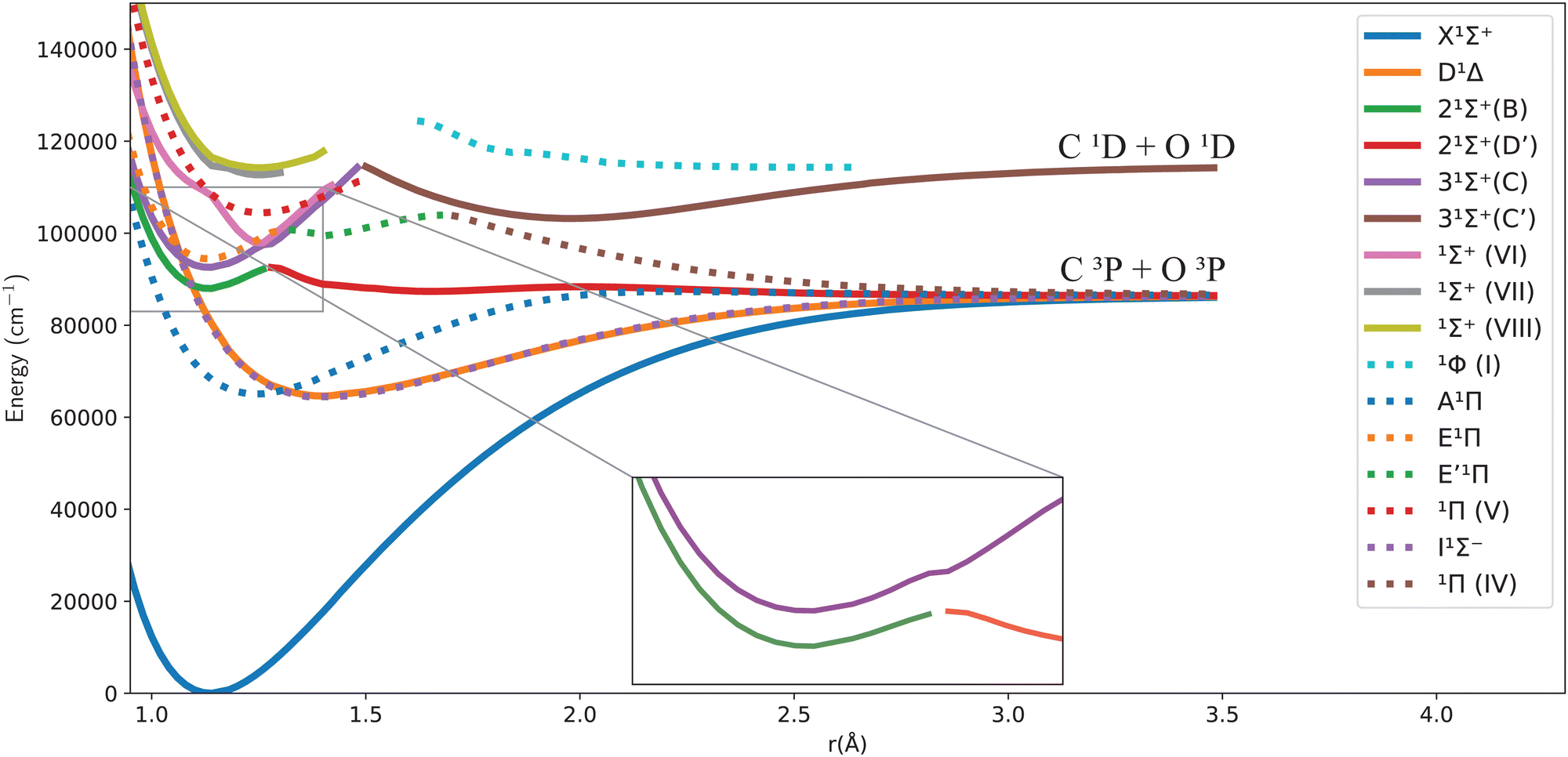 | ||
| Fig. 1 Potential energy curves for the singlet states of CO in the adiabatic representation. | ||
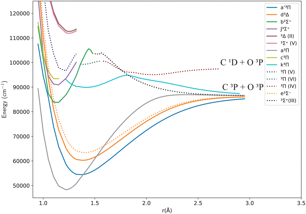 | ||
| Fig. 2 Potential energy curves for the triplet states of CO in the adiabatic representation. | ||
One can notice from Fig. 1 that the potential barrier of the 21Σ+ (or BD′) state is itself avoiding the upper 31Σ+ (or CC′) state in the adiabatic representation. The 31Σ+ state also undergoes an avoided crossing with the 1Σ+(VI) state, located at even higher energy. Given this complicated system, treating the avoided crossings correctly represents an important part of constructing a robust spectroscopic model. More discussion about them and their diabatization is presented below.
It is worth noting that Vázquez et al.40 used the SCF MRSD-CI method with the aug-cc-pVQZ basis set to calculate the potential energy curves of CO; they found an energy difference between the minima of the C1Σ+ and D′1Σ+ states of around 4748 cm−1; they also reported a literature value for the experimentally obtained energy difference of 2476 cm−1. Furthermore, they reported the potential barrier of D′ to be 1048 cm−1 above the dissociation limit C(3P) + O(3P) at 1.980 Å. They suggest that this feature occurs due to an avoided crossing with a (1Σ+) bound state that converges to the C(1D) + O(1D) asymptotic limit or to C(3P) + O(3P) without specifying the exact state. They also calculated Te for the C′1Σ+ valence state of 104![[thin space (1/6-em)]](https://www.rsc.org/images/entities/char_2009.gif) 127 cm−1 compared to the experimental Te value of 102207 cm−1.41
127 cm−1 compared to the experimental Te value of 102207 cm−1.41
The first 1Σ+ valence state (D′1Σ+) causes strong predissociation and perturbations in the Rydberg states (1Σ+).42 The perturbations happen in the (nsσ) Rydberg states of the CO molecule and manifest as an energy shift in the lowest vibrational levels. In particular, the ν = 2 vibrational level of the B1Σ+ state is strongly affected by this perturbation due to electrostatic interaction with the D′1Σ+ valence state.42 The D′1Σ+ state has a weakly bound repulsive part that causes large changes in the vibrational and rotational parameters upon interaction with the B1Σ+ state, as well as significantly increased predissociation rates of the ν = 2 and ν = 3 vibrational energy levels. Strong coupling between the B1Σ+ and D′1Σ+ states leads to a 1Σ+ resonance in the absorption spectra. In general, the strength of the interaction varies as n−3/2, where n is the index of the state within the nsσ series.41 Some vibrational levels of the C′1Σ+ state are accessible from the ν = 0 vibrational level of the ground state at higher energies due to the interaction of the C′1Σ+ state with the B1Σ+ Rydberg state.41 The ν = 0 and ν = 1 levels of the B1Σ+ states have longer lifetimes than the higher vibrational levels and give rise to fluorescence to the A1Π state and the ground state.
The (2–0) B1Σ+–X1Σ+ band has a rotational bandwidth of around 1 to 2 cm−1 (FWHM),43 while the (3–0) band is diffuse, and the higher bands are even broader.39,43 Also, above 100000 cm−1, the absorption of CO is complicated because the molecule undergoes photodissociation.41 Finally, the E1Π state is the second 1Π state and the first 1Π Rydberg state of the CO molecule. It has an experimentally determined minimum energy of 92903 cm−1, which lies above that of the C1Σ+ state.44 It undergoes an avoided crossing with E′1Π at around 1.25 Å.42
In 2004 Eidelsberg et al.41 updated the diabatic potential energy curves published in 1992: the C′1Σ+ state minimum at 1.8 Å is obtained at 107600 cm−1 above the ground state's minimum. Their ab initio calculations underestimate the well depth of the C′1Σ+ state by 5400 cm−1.41
Lu et al.45 calculated the low-lying states of CO in 2012, along with other singlet and triplet states converging to the first dissociation limit, using the cc-pV5Z and aug-cc-pV5Z basis sets and the CASSCF/MRCI+Q (complete active space self-consistent field/multi-reference configuration interaction + Davidson correction) method. They obtained an energy for the lowest vibrational level (v = 0) of the A1Π state of 756.5 cm−1, 3 cm−1 higher than the experimental value (753.5 cm−1). A synthetic spectrum for the A1Π–X1Σ+ band system was calculated by Cheng et al.,46 for which they used MRCI+Q with an aug-cc-pV5Z basis set to calculate the potential energy curves. The authors reported that they did not use a theoretical transition dipole moment (TDM), but instead used an indirect method based on experimental laser-induced fluorescence, to determine an empirical TDM function. Forty vibrational levels were calculated for the ground state (ν′′ = 0–39), and twenty-four levels for the A1Π state (ν′ = 0–23).
Recently, Zhang and Shi14 used the icMRCI+Q method to study selected states of the CO molecule. The B1Σ+ state obtained has one barrier at 1.3 Å, and the potential energy is 6400 cm−1 higher than the dissociation limit at this internuclear distance.
For the ground state, Meshkov et al.29 recently made a semi-empirical function for the ground state permanent dipole moment of CO to construct a new line list. The authors recalculated the intensities of CO isotopologues using new potential energy and dipole moment functions for five vibrational bands within the ground electronic state. They found a deviation in the third and fifth overtones by 1%, and that deviation in the 5–0 band is not significant due to the large uncertainty in the experimental data. Subsequent combined experimental and theoretical work47,48 has provided high accuracy intensities for the (3–0) and (7–0) bands.
This article presents a spectroscopic model of the CO molecule's electronic states. We concentrate on highly excited states, where the adiabatic potential energy and transition dipole moment curves are calculated, followed by diabatization, to produce accurate diabatic potential energy and transition dipole moment curves for the B1Σ+–X1Σ+ and C1Σ+–X1Σ+ transition bands. Synthetic spectra for the A1Π–X1Σ+, B1Σ+–X1Σ+, C1Σ+–X1Σ+, D′1Σ+–X1Σ+ and E1Π–X1Σ+ transitions are computed and compared with the literature.
Additionally, a comparison is made between a diabatic representation with/without diabatic couplings (DCs) and an adiabatic representation without non-adiabatic couplings (NACs), mainly showing an important effect of the diabatic couplings on the line positions. The article is organized as follows: following the introduction given in Section 1, the computational methodology is presented in Section 2. Section 3 is dedicated to the results and discussion, encompassing the electronic structure, diabatization technique, rovibrational calculations, and the impact of the diabatic couplings on the synthetic spectra. The conclusions are given in Section 4.
2 Computational methodology
2.1 Ab initio calculations
The potential energy curves (PECs) and transition dipole moment curves (TDMCs) of the CO molecule were calculated using the MOLPRO 2022.1.2 package,49 using the C2v group symmetry. The MOLPRO code provides an accurate description of the electronic correlation problem.49,50 The calculations of the ground and excited states were investigated using the complete active space self-consistent field (CASSCF) method, followed by an internally contracted MRCI+Q calculation, as done in previous work.51–53 One well-know issue with this methodology is obtaining smooth curves (both PECS and TDMCs) as these often show artificial features due to orbital swapping as a function of bondlength.54As done in previous work,54,55 an augmented triple-ζ correlation-consistent polarized basis (aug-cc-pVTZ)56–58 was used for the carbon and oxygen atoms. Only the spd functions were adopted to decrease computational cost and reduce orbital swapping for smoother-shaped curves. Although not optimal, the truncation of the f functions and the neglect of the higher-level (g, etc.) functions in basis sets used to describe CO-containing complexes has already been tested and has been proven to have little effect on the main physical properties of the molecules.59 Twelve molecular active orbitals were considered, labeled as [6a1, 3b1, 3b2, 0a2] in the C2v point group, resulting from 6σ and three pairs of π orbitals mainly built from C: 2s, 2p, 3s, 3p and O: 2s, 2p shells. The C 1s and O 1s orbitals are kept doubly occupied in all configurations. In the CAS-SCF calculation, the ten CO valence electrons were distributed into the twelve valence molecular orbitals hence, this active space is referred to as CAS (10, 12). The four inner electrons were placed into the two closed-shell orbitals, which included only two a1 symmetry molecular orbitals, corresponding to the 1σ and 2σ molecular orbitals in the CO molecule. There was no change in the total orbital space in the subsequent MRCI calculations.
Using the notation [A1,B1,B2,A2], the number of states in the irreducible representations of the C2v point group considered in the CASSCF calculations is [8,3,3,2] which means 8 A1, 3 B1, 3 B2 and 2 A2. This [8,3,3,2] states model was used to compute potential energy curves and transition dipole moments for the B1Σ+–X1Σ+, C1Σ+–X1Σ+, D′1Σ+–X1Σ+ and E1Π–X1Σ+ bands. However, a [6,3,3,2] states model was used to calculate potential energy curves and transition dipole moments for the A1Π–X1Σ+ band because the shape of the potential energy curve is slightly different around the minimum for the two CASSCF orbital sets. The choice of six A1 states gave more accurate line positions for A1Π–X1Σ+ transitions. Identical energy values for degenerate states were validated for all the calculated potential energy curves.
States with A1 and A2 symmetry were only considered in the MCSCF/CASSCF calculations in the region from 0.9 to 1.14 Å, for the singlet states, because of insufficient overlap in the configuration interaction (CI) for the higher states. Excellent agreement was obtained by superimposing the MRCI results from MCSCF/CASSCF calculations that includes only A1 and A2 and MCSCF/CASSCF calculations that includes A1, B1, B2, and A2, in the range from 1.18 to 3.4 Å, which allowed us to use the assumption as a valid extrapolation of the curves outside the 0.9 to 1.14 Å region. Many of the alternative models encountered issues with the active space adopted, such as avoided crossing sometimes moving according to the configuration used and configuration interaction calculations giving inefficient overlap error over the whole range of internuclear distances.
2.2 Diabatization
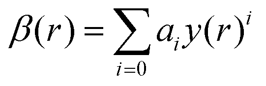
The ab initio PECs of CO shown in Fig. 1 and 2 are given in the so-called adiabatic representations. The adiabatic representation consists of a set potential energy curves, in which the electronic Hamiltonian is diagonal, a non-diagonal kinetic energy matrix consisting of non-adiabatic couplings (NACs) and diagonal Born–Oppenheimer corrections (DBOCs). It is common to omit the NAC terms and this has proven to be useful in predicting near equilibrium properties for many molecules.60 NACs arise between different electronic states of the same symmetry through action of the nuclear kinetic energy operator on the electronic wavefunctions and correspond to first derivative couplings. The associated PECs in the adiabatic representation are then characterized by avoided crossings near degeneracy,61 at which the NAC terms are strongest.62–65 In the region of the avoided crossing, the adiabatic PECs can have complex shapes, and the NACs are cusp-like. This is undesirable to treat computationally and represent analytically, especially as such topology can be sensitive to the quality of ab initio calculations. Conversely, a diabatic representation of the potential energy curves (as well as associated couplings) exists where NACs vanish simultaneously with the DBOC terms via a bond-length-dependent unitary transformation U(r), and is characterised by a set of PECs that cross at the cost of introducing diabatic couplings (DCs).66–68The diabatizing unitary matrix U(r) for the coupled two-electronic state system parametrically depends on the NACs through the mixing angle β(r) and is equivalent to the two-dimensional rotation matrix given by
 | (1) |
The mixing angle relates the diabatizing transformation to the NAC ϕ12(r) through its integral via
 is the NAC and β(r0) is chosen to ensure physical conditions on the adiabatic–diabatic transformation. |ψ1〉 represents the adiabatic lower energy electronic wavefunction and |ψ2〉 represents the adiabatic upper energy electronic wavefunction. The adiabatic representation of PECs for these two states is given by
where Va1(r) and Va2(r) are the adiabatic lower and upper PECs, respectively. The diabatic Hamiltonian is then calculated by applying the unitary matrix to the above adiabatic potential matrix, yielding
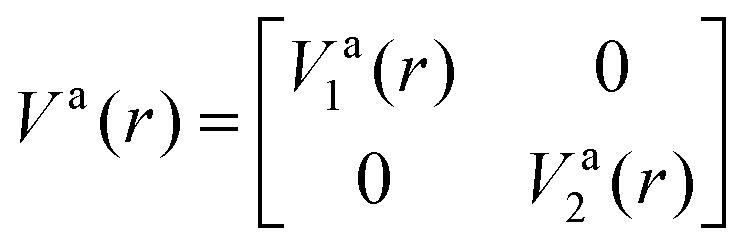
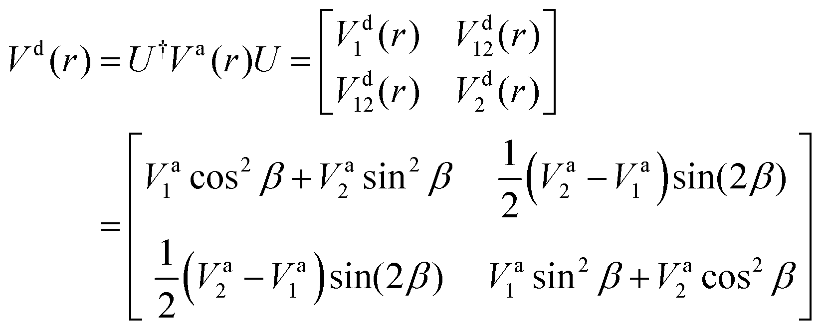
The superscript “d” refers to the diabatic basis and “a” refers to the adiabatic one, while the off-diagonal terms Vd12(r) are the DCs.
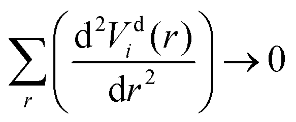
The diabatization method we adopt follows the approach extensively tested by Brady et al.69 where, instead, the diabatizing transformation and associated NACs are computed via a property-based method using the code presented by Brady et al.,70 as opposed to directly from the NACs. The result being smooth diabatic PECs that are easily parameterised. This method works by optimising a NAC that, when used to transform the ab initio adiabatic PECs to the diabatic representation, produces the smoothest diabatic PECs by minimising the following loss function
 | (2) |
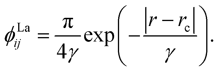
We chose to model the NACs by the combination of a Lorentzian and Laplacian function through the geometric average of their corresponding mixing angles (see Brady et al.70 and An and Baeck71 for details). The Lorentzian function tends to underestimate the NAC at the avoided crossing but overestimates them at large distances from the avoided crossing.71–73 Conversely, the Laplacian underestimates the NAC away from the avoided crossing and overestimates the NAC at the avoided crossing. Therefore, their combination ensures the functions’ undesirable properties are mitigated. The Lorentzian NAC curve is given by
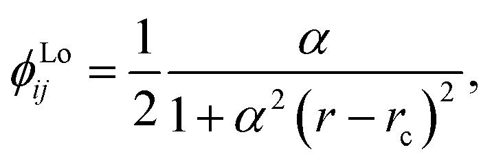 | (3) |
 | (4) |
In this work, we use the diabatic representation for the solution of the nuclear motion Schrödinger equation and calculate spectra of CO with the corresponding PECs and DCs computed using the property-based diabatization technique. More details on the diabatization procedure specific to the investigated CO system are given in Section 3.2. The diabatic curves obtained were used in generating the synthetic spectra discussed later on in Section 3.3.
2.3 Rovibrational calculations
Spectral calculations were performed using the Duo variational nuclear-motion program,74,75 which treats the rovibronic problem for open shell diatomic molecules by solving numerically the coupled Schrödinger equation. The main output from Duo is a molecular line list. In this paper, Duo is used to calculate line lists for the A1Π–X1Σ+, B1Σ+–X1Σ+, C1Σ+–X1Σ+, D′1Σ+–X1Σ+, and E1Π–X1Σ+ electronic band systems individually. A uniform grid of 501 points was set to solve the coupled Schrödinger equation using the sinc DVR (discrete variable representation) basis set. The calculations are done over a range from 1 to 3.5 Å for A1Π–X1Σ+, from 0.92 to 2 Å for the B1Σ+–X1Σ+, from 0.92 to 1.5 Å for C1Σ+–X1Σ+, from 0.88 to 1.26 Å for E1Π–X1Σ+, and from 0.75 to 2 Å for D′1Σ+–X1Σ+. The maximum energy limit was set to 130000 cm−1 in our model, and the maximum rotational quantum number J was set to 110.
The ground state X1Σ+ and excited A1Π state PECs were represented by the Extended Morse Oscillator (EMO) function.76 The EMO function is given by the following equation:74
| V(r) = Te + (Ae − Te)(1 − exp[−β(r)(r − re)])2 | (5) |
 | (6) |
| y(r) = (rp − rpe)/(rp + rpe). | (7) |
T e is the minimum electronic energy, Ae is the asymptotic limit, and re is the equilibrium separation. The initial values of the EMO expansion coefficients were obtained by fitting to the ab initio values using the CurveExpert software77 before being introduced in Duo in the form of grids. Following the fitting procedure, the PECs were shifted to align with the Te and re values taken from Huber and Herzberg.44 In more detail, the PEC of A1Π was shifted by 0.0105 Å and 27.24 cm−1 to assure this alignment. Similar matching of the Te and re values were used by Semenov et al.78 for the PN molecule. For the ab initio B1Σ+ and C1Σ+ PECs, a similar procedure was followed, where ninth-degree polynomials were used as fitted with ORIGIN.79 The ESI† contains the PEC grids (initial ab initio data and as introduced in Duo) and proposed fitting parameters.
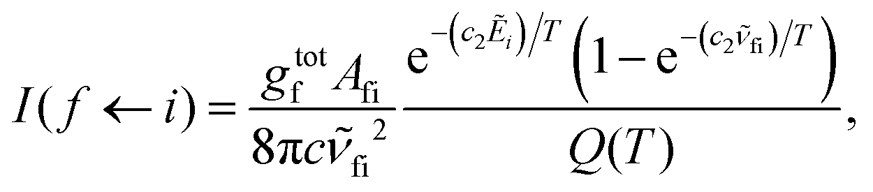
Absorption spectra for each band were simulated using the code ExoCross.80 ExoCross produces spectra and absorption cross-sections at pre-specified temperature using the line list in the ExoMol format81 generated by Duo as an input. For each comparison with the experiment, the experimental conditions of temperature and pressure are used as input. The line intensity (absorption coefficient, cm per molecule) is calculated using the following equation:80
 | (8) |
![[small nu, Greek, tilde]](https://www.rsc.org/images/entities/i_char_e0e1.gif) fi is the transition wavenumber (cm−1), Afi is the Einstein A coefficient (s−1), Ẽi = Ei/hc is the energy term value (cm−1), T is the temperature in K, c2 is the second radiation constant (c2 = hc/kB) in cm K, and Q(T) is the partition function
fi is the transition wavenumber (cm−1), Afi is the Einstein A coefficient (s−1), Ẽi = Ei/hc is the energy term value (cm−1), T is the temperature in K, c2 is the second radiation constant (c2 = hc/kB) in cm K, and Q(T) is the partition function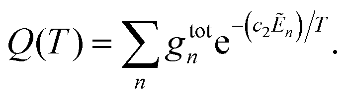
Here, gtotn is the total degeneracy gtotn = gns(2Jn + 1) that is a function of the nuclear-spin statistical weight factor (gns), which equals 1 for 12C16O, and the rotational quantum number of the nth level (Jn).80
3 Results and discussion
3.1 Electronic structure
Fig. 1 and 2 show the adiabatic potential energy curves for singlet and triplet states of the CO molecule, respectively, over a range of internuclear distances (0.95 to 3.5 Å). The asymptotic limit has been corrected to eliminate the numerical/computational error that caused its slight upward shift. A similar case is depicted as numerical noise by Brady et al.70 in their ab initio data for SO. The error resulted in a shift of approximately 0.27 to 0.33% in the corrected asymptote, and it has been rectified in our data. This problem occurs beyond 2.66 Å, a region that was not utilized to generate the synthetic spectrum. The lowest dissociation limits of the calculated low-lying electronic states of the CO molecule have been compared with the combination of atomic term values provided by the National Institute of Standards and Technology (NIST) Atomic Spectra Database,82 using the Wigner–Witmer correlation rules,83 to confirm that this correction is valid. The relative error for the asymptotic limit of the second singlet states C(1D) + O(1D) was calculated before and after correction. It was found that the relative error when compared to NIST values, decreased from 9% to 7%.The singlet states obtained show double-well structures in the adiabatic representation, such as in the case of BD′ and CC′ states. Some valence electronic states such as D′ and C′ have shallow wells due to overcoming the repulsive forces over the attractive ones within the range of the internuclear distances considered.50 The other low-lying states mostly have wells, except for the repulsive 1Π(IV) state. The depth of the potential energy curve indicates the bond strength and the stability of the molecule in the specified state.84
The D′1Σ+ state almost overlaps with the I1Σ− state as portrayed by the similarity of their spectroscopic constants. The difference in the minimum energy between them is approximately 293.8 cm−1 at their equilibrium bond length of 1.4 Å (see Table 2 below).
The B1Σ+ state is described as having the configuration (4σ25σ11π43sσ) while D′1Σ+ state was given as (4σ25σ21π32π). Most probably, the D′1Σ+ potential barrier at 2 Å results from an avoided crossing with C′1Σ+ that converges to the C(1D) + O(1D) asymptotic limit.40
The potential barrier in the BD′ state is calculated by Vázquez et al.40 to be at R = 1.32 Å, which is longer than our value by 0.04 Å and that obtained by Zhang and Shi14 using an icMRCI+Q calculation, by 0.02 Å.
Cooper and Kirby33 calculated adiabatic potential energy curves using Slater type basis set in MCSCF-CI calculations that are singly excited. The avoided crossing of the BD′ state with the C1Σ+ state is slightly visible in their calculation at around 1.32 Å. Li et al.21 conducted an adiabatic calculation for the B1Σ+ and C1Σ+ states using MRD-CI. They used non-adiabatic couplings and nuclear kinetic energy corrections to estimate the diabatic effects. The maximum calculated value of the NAC was close to 1.25a0−1 at 1.286 Å where the avoided crossing point is situated, which is close to the avoided crossing position value we obtain in our calculations.
Li et al.21 reported that the BD′ state consists of the B1Σ+ Rydberg state and D′1Σ+ valence state character (π3π*3),21 while C1Σ+ state is mixed between the Rydberg (2sσ) and (3pσ) and D′1Σ+ valence character. The same authors conclude that the BD′ state has an observed second energy well, which supports three vibrational levels,21 similar to the bound region of the D′1Σ+ state obtained in the present study.
The second adiabatic 1Π state has two avoided crossings. The first one is between E1Π and E′1Π, and the second one is between E′1Π and the unbound 1Π(IV) state40,42 that we obtain in our calculations.
The term values TvJ of a vibrating rotator can be expressed as a function of the minimum electronic energy Te, the vibrational constant ωe, the first, second and third order anharmonicity constants ωexe, ωeye, and ωeze, the vibrationally averaged rotational constant Bv, and the vibrationally averaged centrifugal distortion constant, Dv through the equation:83
 | (9) |
| Bν = Be − αe(ν + 1/2) + γe(ν + 1/2)2 + δe(ν + 1/2)3 + … | (10) |
| Be = h/(8π2cIe) | (11) |
Here, h is Planck's constant, Ie is the moment of inertia of the molecule at the equilibrium bond distance, and c is the speed of light. Similarly, Dv can be expressed in terms of the equilibrium centrifugal distortion constant De, and the first, second and third order vibration–rotation interaction constants βe,  and
and  as:
as:
 | (12) |
| De = 4Be3/ωe | (13) |
The spectroscopic constants of the electronic states of CO molecule obtained in this work were calculated using a polynomial fitting program. Their comparison with theoretical/experimental data from the literature is presented in Table 2. Our results show excellent agreement with the available results for most calculated states.
The calculated equilibrium internuclear distance Re and rotational constant Be for the ground state X1Σ+ of the CO molecule agree well with the ref. 33, 44, 45 and 85–88, with relative error of 0.07% ≤ ΔRe/Re ≤ 0.86% and 0.97% ≤ ΔBe/Be ≤ 1.75%. Also, the A1Π state has an equilibrium internuclear distance of 1.24 Å and Te value of 65036.27 cm−1 which corresponds to a relative error of 0.14% ≤ ΔRe/Re ≤ 0.87% and 0.06% ≤ ΔTe/Te ≤ 2.73%, with respect to the experimental values reported by Herzberg,44 O’Neil and Schaefer,89 as well as other theoretical studies by Vázquez et al.,40 Cooper and Kirby,33 Lu et al.,45 Chantranupong et al.,85 Shi et al.,86 Majumder et al.90
The adiabatic electronic excitation threshold (Te) of the Hopfield–Birge band states B1Σ+ and C1Σ+ is calculated to be 87964.43 and 92566.1 cm−1, respectively. The relative error for the B1Σ+ is 0.77% ≤ ΔTe/Te ≤ 1.190% and 0.1% ≤ ΔTe/Te ≤ 0.71% for the C1Σ+ state when compared to Huber and Herzberg,44 Vázquez et al.,40 Eidelsberg et al.,91 Eidelsberg and Rostas,92 respectively.
The valence state D′1Σ+ has a calculated equilibrium internuclear distance of 1.650 Å and Te value of 87338.05 cm−1 which corresponds to a relative error of 2.44% ≤ Δre/re ≤ 4.45% and −0.65% ≤ ΔTe/Te ≤ −2.35%, with respect to the experimental and theoretical values reported by Wolk and Rich,37 Vázquez et al.,40 respectively. The minimum energy of the E1Π state is 94408.3 cm−1 at 1.130 Å, which corresponds to a relative error of 0.82% ≤ Δre/re ≤ 1.44% and 1.62% ≤ ΔTe/Te ≤ 1.9%, with respect to the experimental and theoretical values reported by Vázquez et al.,40 Huber and Herzberg,44 respectively.
Fig. 3 shows our A1Π–X1Σ+ calculated transition dipole moment that is fitted to a ninth-degree polynomial with a standard deviation of the residuals 0.01 a.u. It shows good agreement with the curves extracted from literature.14,35,45,85,88
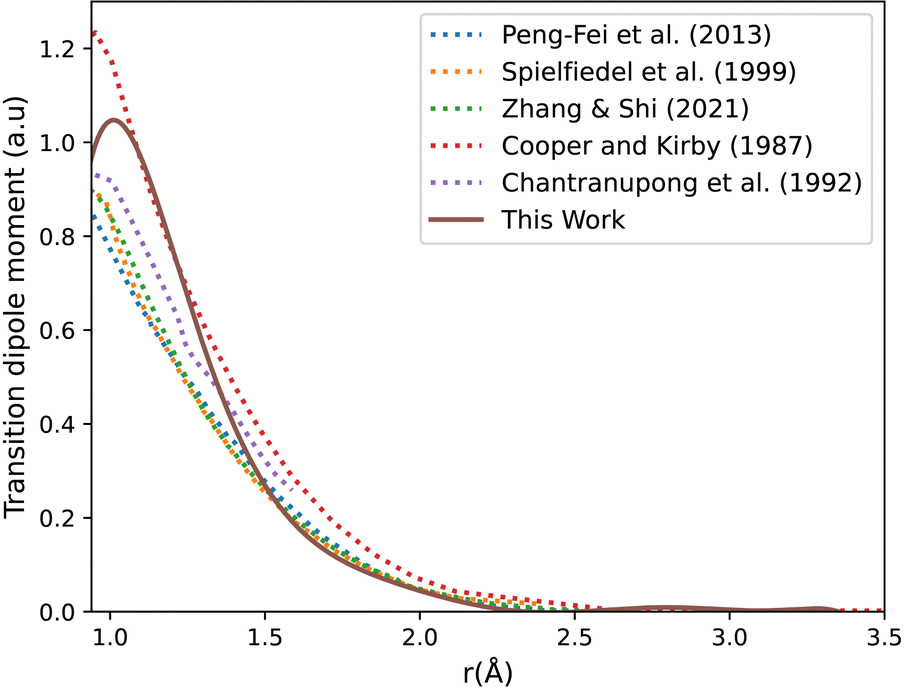 | ||
| Fig. 3 CO A1Π–X1Σ+ transition dipole moment curves: ours compared to literature curves.35,45,85,88 | ||
The adiabatic transition dipole moment curves (TDMCs) used in the calculations are shown in Fig. 4. The E1Π–X1Σ+ TDMC is calculated in the adiabatic representation (its diabatic representation is out of scope of this work), so only the portion before the avoided crossing of the transition dipole moment is considered for this state.
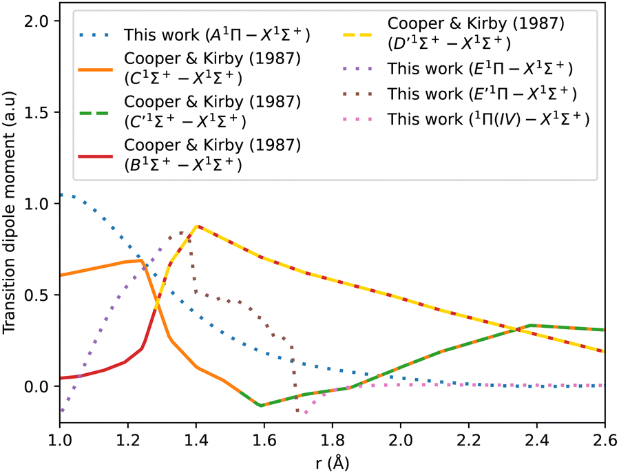 | ||
| Fig. 4 Transition dipole moment curves for A1Π–X1Σ+, B1Σ+–X1Σ+, C1Σ+–X1Σ+, E1Π–X1Σ+, E′1Π–X1Σ+, and 1Π(IV)–X1Σ+. | ||
As can be seen in Fig. 1, the adiabatic 1Π states E1Π, E′1Π and 1Π(IV) undergo avoided crossings between each other. Fig. 4 displays their TDMs for transitions with the X1Σ+ state. Different regions of the TDM are assigned for each state by different colours.
The electronic structure ab initio curves presented by Kirby and Cooper35 appear to closely resemble ours, with a slight difference in the region around the avoided crossing. The shift observed in our curves beyond 2.66 Å is typical in the excited states of CO as MOLPRO calculations become particularly noisy in this region due to orbital swapping.93
The diabatic transition dipole moment curves for the B1Σ+–X1Σ+ and C1Σ+–X1Σ+ systems were constructed from Kirby and Cooper's adiabatic transition dipole moment curves. In fact, the crossing point between the B1Σ+–X1Σ+ and C1Σ+–X1Σ+ TDM's in our data occurs at 1.40 Å, whereas in Kirby and Cooper35 data, it is at 1.28 Å. At the same time, Kirby and Cooper35's TDMs are smoother and show more consistency in the range investigated. Consequently, the diabatization procedure followed resulted in more conclusive results using their calculated TDMs than when our own dipole curves were used. All other transition dipole moment curves used in this paper are our calculated curves. It is worth mentioning that Kirby and Cooper35 potential energy curves are also shifted with respect to their transition dipole moment curves’ crossing point by 0.04 Å.
3.2 Diabatized potential energy and transition dipole moment curves
As stated in the introduction, the 21Σ+ (or BD′) state which is constituted by the Rydberg B1Σ+ and valence D′1Σ+ states, makes an avoided crossing with the upper 31Σ+ (or CC′) state in the C1Σ+ region of the curve, close to 1.28 Å. The CC′ state also makes another avoided crossing with the higher Σ+(IV) state. There is also an avoided crossing at about 2 Å between the D′1Σ+ and C′1Σ+ states but it is not considered here as it is distant from the 1.28 Å region. In this work, we simplify the complexity of the 3-level system constituted of the 21Σ+, 31Σ+ and Σ+(IV) states, and instead aim to produce a physically meaningful model of CO that gives a good spectroscopic model using initially a 2-level system which would be sequentially related to the remaining state, leading to a 3-levels system. We will first concentrate on the avoided crossings between the BD′ and C1Σ+ states (Section 3.2.1), then use the obtained results to make deductions about the avoided crossing between the C1Σ+ and Σ+(IV) states (Section 3.2.2).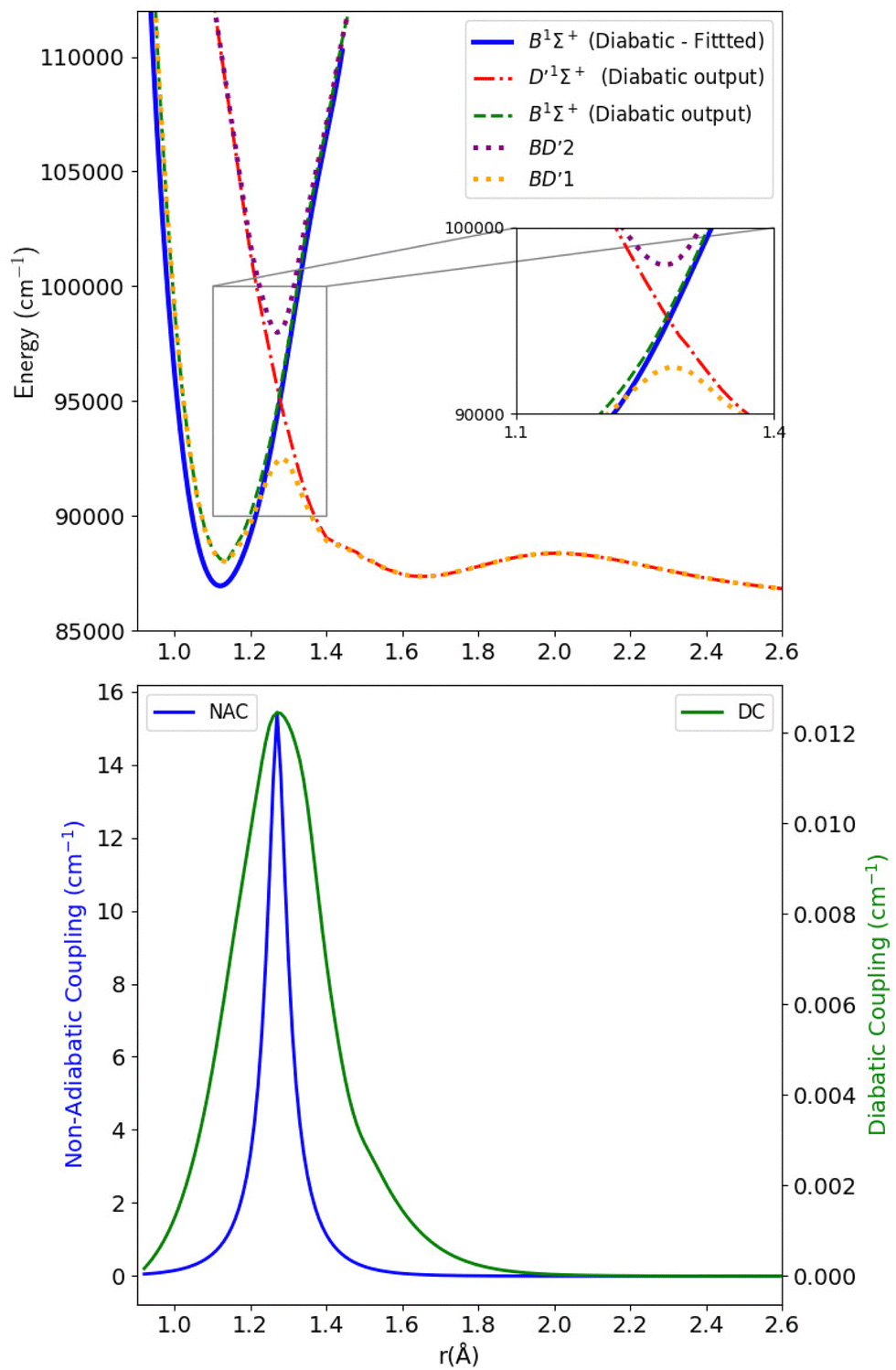 | ||
| Fig. 5 Upper panel: Adiabatic and diabatic potential energy curves for the BD′ system. Lower panel: The NACs and DCs of the BD′ system. | ||
The thick blue solid line represents the B1Σ+ state curve after fitting to the experimental Te and re spectroscopic constants values. The NACs for the BD′ system are very small, with a maximum value of 15.418 cm−1 at the crossing point (Fig. 5). The small value of NACs indicates weak interaction between the B1Σ+ and D′1Σ+ states at the crossing point.70 In addition, the maximum value of the diabatic couplings is minimal (0.013 cm−1). These were smoothed, before being introduced to Duo, with the Savitzky–Golay digital signal processing method with a value of standard deviation of residuals σr = 0.0000313 cm−1.
Fig. 6 shows the adiabatic and diabatic transition dipole moment curves used in the B1Σ+–X1Σ+ transition calculations. The dotted curves35 are adiabatic TDMs, corresponding to transitions to the ground state, for which the adiabatic C1Σ+ state fitted and extrapolated part is denoted as BD′2, and the adiabatic B1Σ+ state is denoted as BD′1. The solid lines represent the B1Σ+–X1Σ+ and the D′1Σ+–X1Σ+ diabatic TDMs.
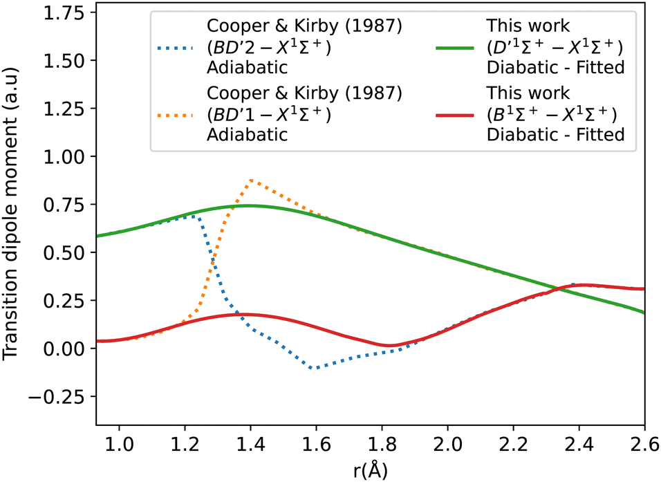 | ||
| Fig. 6 Adiabatic and diabatic B1Σ+–X1Σ+ transition dipole moment curves. | ||
The polarity in the diabatic B1Σ+–X1Σ+ curve was corrected by flipping its sign beyond 1.87 Å, allowing it to follow the polarity of the BD′2–X1Σ+ curve. This adjustment is akin to inducing two flips to account for the simplification of the 3-level system to a 2-level system. Both diabats are smoothed after the diabatization procedure because the ones obtained directly from the diabatization process exhibit a jump at the avoided crossing, also possibly due to numerical errors arising from the simplification of the 3-level system to a 2-level system. The B1Σ+–X1Σ+ TDM used in the calculation is smoothed using a Savitzky–Golay filter and cubic spline with 0.0037 a.u. value of residuals standard deviation (σr). The accuracy of the shape of the transition dipole was tested by comparing the intensity of the B–X (1–0) to B–X (0–0) bands. Our calculated relative intensity (RI) is 0.065, which agrees well with the experimental values of Imhof et al.94 (RI = 0.066), and Chan et al.95 (RI = 0.067). Furthermore, the quasi C1Σ+–X1Σ+ TDM not used in the calculations is also smoothed using an eighth-degree polynomial with σ = 0.033 a.u.
The diabatization smooths out the curves and eliminates the steep gradient caused by the avoided crossing in the adiabatic representation. The derivative of the dipole moment with respect to internuclear distance (r) affects the vibronic intensities. So, having diabatic curves will reduce the inaccuracy and errors in the spectral properties of the molecule because there is no sudden jump in the diabatic curves as in the case of the adiabatic ones.74
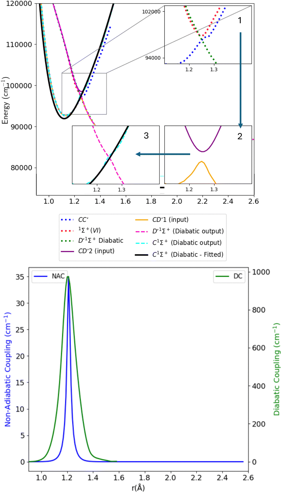 | ||
| Fig. 7 Upper panel: Adiabatic and diabatic potential energy curves for CD′ system. Lower panel: The NACs and DCs of the CD′ system. | ||
Table 1 provides values for the optimized NAC parameters α, γ, rc used to diabatize the BD′ and CD′ systems, which are visualised in Fig. 5 and 7.
| System | α | γ | r c (Å) |
|---|---|---|---|
| BD′ | 29.937 | 0.047 | 1.275 |
| CD′ | 72.458 | 0.019 | 1.246 |
| Ref. | State | r e (Å) | r e |RE%| | ω e (cm−1) | ω e |RE%| | ω e x e (cm−1) | ω e x e |RE%| | B e (cm−1) | B e |RE%| | T e (cm−1) | T e |RE%| |
|---|---|---|---|---|---|---|---|---|---|---|---|
| This work | X1Σ+ | 1.14 | 2125.45 | 12.29 | 1.90 | 0 | |||||
| 44* | X1Σ+ | 1.13 | 0.86 | 2169.81 | 2.04 | 13.29 | 7.53 | 1.93 | 1.75 | 0 | |
| 45 | X1Σ+ | 1.13 | 0.47 | 2141.70 | 0.76 | 12.34 | 0.43 | 1.92 | 0.97 | 0 | |
| 87 | X1Σ+ | 1.13 | 0.36 | 2000 | 6.27 | 0 | |||||
| 33 | X1Σ+ | 1.14 | 0.07 | 2151.60 | 1.22 | 12.90 | 4.75 | 0 | |||
| 85 | X1Σ+ | 1.13 | 0.67 | 2178 | 2.41 | 13.00 | 5.48 | 0 | |||
| 88 | X1Σ+ | 1.13 | 0.72 | 2170 | 2.05 | 13.90 | 11.60 | 0 | |||
| 86 | X1Σ+ | 1.13 | 0.83 | 2169.47 | 2.03 | 13.74 | 10.57 | 1.93 | 1.69 | 0 | |
| 89 | X1Σ+ | 1.24 | 8.22 | 1854 | 14.64 | 13.88 | 11.47 | 1.61 | 17.85 | 0 | |
| This work | a3Π | 1.22 | 1729.45 | 21.24 | 1.66 | 48247.09 |
|||||
| 98* | a3Π | 1.21 | 0.89 | 1738.26 | 0.51 | 14.25 | 49.03 | 48686.70 |
0.90 | ||
| 45 | a3Π | 1.21 | 0.49 | 1743.41 | 0.80 | 14.97 | 41.86 | 1.68 | 1.03 | 48796.40 |
1.13 |
| 86 | a3Π | 1.25 | 2.74 | 1748.12 | 1.07 | 14.39 | 47.58 | 1.69 | 1.81 | 48650 |
0.83 |
| 89 | a3Π | 1.33 | 8.54 | 1488 | 16.23 | 17.80 | 19.31 | 1.39 | 19.47 | 42102.10 |
14.60 |
| 89* | a3Π | 1.21 | 0.53 | 1743 | 0.78 | 14.50 | 46.46 | 1.69 | 1.74 | 48715.90 |
0.96 |
| This work | a′3Σ+ | 1.36 | 1177.20 | 29.61 | 1.33 | 54371.28 |
|||||
| 44* | a′3Σ+ | 1.35 | 0.59 | 1228.60 | 4.18 | 10.47 | 182.84 | 1.34 | 1.14 | 55825.40 |
2.60 |
| 45 | a′3Σ+ | 1.36 | 0.19 | 1214.10 | 3.04 | 9.27 | 219.56 | 1.33 | 0.21 | 55566.27 |
2.15 |
| 87 | a′3Σ+ | 1.35 | 1.13 | 1240 | 5.06 | 55540 |
2.10 | ||||
| 89 | a′3Σ+ | 1.48 | 8.09 | 1147 | 2.63 | 10.60 | 179.31 | 1.18 | 12.65 | 40811.60 |
33.23 |
| 89* | a′3Σ+ | 1.35 | 0.76 | 1231 | 4.37 | 11 | 169.16 | 1.35 | 1.54 | 55813.50 |
2.58 |
| This work | d3Δ | 1.38 | 1075.77 | 28.45 | 1.30 | 60226.69 |
|||||
| 44* | d3Δ | 1.37 | 0.47 | 1171.94 | 8.21 | 10.64 | 167.52 | 1.31 | 0.84 | 61120.10 |
1.46 |
| 45 | d3Δ | 1.37 | 0.15 | 1158.64 | 7.15 | 9.09 | 212.92 | 1.30 | 0.02 | 60881.80 |
1.08 |
| 86 | d3Δ | 1.37 | 0.49 | 1175 | 8.44 | 10.75 | 164.76 | 1.31 | 0.87 | 61147.60 |
1.51 |
| 89 | d3Δ | 1.50 | 8.26 | 1107 | 2.82 | 11.20 | 154.02 | 1.09 | 19.24 | 48877.20 |
23.22 |
| 89* | d3Δ | 1.37 | 0.44 | 1153 | 6.70 | 7.20 | 295.15 | 1.31 | 0.78 | 61136.80 |
1.49 |
| This work | e3Σ− | 1.40 | 1027.51 | 9.66 | 1.26 | 63375.71 |
|||||
| 44* | e3Σ− | 1.38 | 1.07 | 1117.70 | 8.07 | 10.69 | 9.63 | 1.28 | 2.08 | 64230.20 |
1.33 |
| 89 | e3Σ− | 1.51 | 7.36 | 1062 | 3.25 | 12.20 | 20.85 | 1.07 | 17.47 | 51458.10 |
23.16 |
| 89* | e3Σ− | 1.38 | 1.36 | 1114 | 7.76 | 9.60 | 0.59 | 1.28 | 1.80 | 64201.70 |
1.29 |
| 90 | e3Σ− | 1.39 | 0.63 | 1106.60 | 7.15 | 9.62 | 0.38 | 63747.90 |
0.58 | ||
| This work | I1Σ− | 1.40 | 1041.22 | 53.63 | 1.25 | 64366.6 |
|||||
| 44* | I1Σ− | 1.39 | 0.62 | 1092.22 | 4.67 | 10.70 | 1.27 | 1.33 | 65084.40 |
1.10 | |
| 45 | I1Σ− | 1.40 | 0.16 | 1058.71 | 1.65 | 9.79 | 1.25 | 0.28 | 65644.26 |
1.95 | |
| 86 | I1Σ− | 1.39 | 0.63 | 1094.75 | 4.89 | 10.71 | 1.27 | 1.34 | 65087.21 |
1.11 | |
| 89 | I1Σ− | 1.55 | 9.70 | 955 | 9.03 | 14.90 | 259.93 | 1.03 | 21.71 | 53716.50 |
19.83 |
| 89 | I1Σ− | 1.39 | 0.70 | 1092 | 4.65 | 10.80 | 396.57 | 1.27 | 1.29 | 65088.90 |
1.11 |
| This work | D1Δ | 1.40 | 1107.71 | 29.92 | 1.26 | 64660.4 |
|||||
| 44* | D1Δ | 1.40 | 0 | 1094 | 1.25 | 10.20 | 193.37 | 1.26 | 0.15 | 65928 |
1.92 |
| 89 | D1Δ | 1.56 | 10.32 | 905 | 22.40 | 12.40 | 141.32 | 1.01 | 24.27 | 54442.40 |
18.77 |
| 89* | D1Δ | 1.40 | 0.07 | 1080 | 2.57 | 10 | 199.24 | 1.26 | 0.39 | 65976.10 |
1.99 |
| This work | A1Π | 1.24 | 1497.22 | 15.12 | 1.59 | 65036.27 |
|||||
| 40 | A1Π | 1.24 | 0.59 | 1461.20 | 2.47 | 4.40 | 243.70 | 64755.70 |
0.43 | ||
| 44* | A1Π | 1.24 | 0.73 | 1518.20 | 1.38 | 19.40 | 22.05 | 1.61 | 1.54 | 65075.70 |
0.06 |
| 45 | A1Π | 1.24 | 0.29 | 1505.20 | 0.53 | 17.30 | 12.58 | 1.60 | 0.64 | 65125.50 |
0.14 |
| 33 | A1Π | 1.25 | 0.41 | 1475 | 1.51 | 18.90 | 19.98 | 66863.30 |
2.73 | ||
| 85 | A1Π | 1.24 | 0.14 | 1496 | 0.08 | 18.10 | 16.45 | 65653.50 |
0.94 | ||
| 88 | A1Π | 1.23 | 0.87 | 1514 | 1.11 | 18 | 15.98 | 65492.20 |
0.70 | ||
| 86 | A1Π | 1.23 | 0.77 | 1523.75 | 1.74 | 19.20 | 21.23 | 1.77 | 10.14 | 65116.30 |
0.12 |
| 89 | A1Π | 1.36 | 8.50 | 1357 | 10.33 | 22.80 | 33.67 | 1.33 | 19.30 | 57104 |
13.89 |
| 89* | A1Π | 1.24 | 0.35 | 1516 | 1.24 | 17.30 | 12.58 | 1.61 | 1.45 | 65072.80 |
0.06 |
| 90 | A1Π | 1.24 | 0.51 | 1509.50 | 0.81 | 17.50 | 13.58 | 65076.40 |
0.06 | ||
| This work | b3Σ+ | 1.11 | 3163.71 | 228.22 | 1.98 | 82912.24 |
|||||
| 44* | b3Σ+ | 1.11 | 0.03 | 2199.30 | 43.85 | 1.99 | 0.09 | 83814 |
1.08 | ||
| This work | 3Σ+(III) | 2.70 | 877.58 | 0 | 0.34 | 86774.02 |
|||||
| This work | D′1Σ+ | 1.65 | 551.77 | 30.68 | 0.90 | 87338.05 |
|||||
| 91* 92* | D′1Σ+ | 1.58 | 4.45 | 651.40 | 15.29 | 20.40 | 50.39 | 89438.40 |
2.35 | ||
| 40 | D′1Σ+ | 1.61 | 2.44 | 681.70 | 19.06 | 13.40 | 128.96 | 87912 |
0.65 | ||
| 37* | D′1Σ+ | 1.58 | 4.45 | 651.40 | 15.29 | 20.40 | 50.39 | 0.98 | 89438.40 |
2.35 | |
| This work | B1Σ+ | 1.13 | 2152.16 | 62.35 | 1.92 | 87964.43 |
|||||
| 91* 92* | B1Σ+ | 1.12 | 0.98 | 2161.70 | 0.44 | 39.80 | 56.66 | 86926.90 |
1.19 | ||
| 40 | B1Σ+ | 1.12 | 0.60 | 2093 | 2.83 | 15.70 | 297.14 | 87292.80 |
0.77 | ||
| 44* | B1Σ+ | 1.12 | 0.98 | 2112.70 | 1.87 | 15.20 | 310.21 | 1.96 | 2.02 | 86945.20 |
1.17 |
| This work | k3Π | 1.41 | 652.31 | 89916.37 |
|||||||
| 40 | k3Π | 1.33 | 5.60 | [882.7] | 90491.40 |
0.64 | |||||
| 99 | k3Π | 1.38 | 2.08 | 805.10 | 18.98 | −2.85 | 1514.73 | 91012.20 |
1.20 | ||
| This work | J3Σ+ | 1.13 | 2101.30 | 23.34 | 1.91 | 90837.12 |
|||||
| 44* | J3Σ+ | 1.14 | 0.89 | 2166 | 2.99 | 15 | 55.6 | 1.88 | 1.63 | 90975 |
0.15 |
| This work | C1Σ+ | 1.13 | 2119.10 | 35.63 | 1.92 | 92566.1 |
|||||
| 91* 92* | C1Σ+ | [1.1248] | 2189 | 3.19 | 17.33 | 105.61 | 91914 |
0.71 | |||
| 40 | C1Σ+ | 1.12 | 0.82 | 2183.12 | 2.93 | 16.18 | 120.23 | 92659.80 |
0.10 | ||
| 44* | C1Σ+ | 1.12 | 0.78 | 2175.90 | 2.61 | 14.70 | 142.40 | 1.95 | 91916.50 |
0.71 | |
| This work | E1Π | 1.13 | 2121.27 | 30.97 | 1.92 | 94408.3 |
|||||
| 44* | E1Π | 1.12 | 1.44 | 2153 | 1.47 | 42 | 26.26 | 1.98 | 2.88 | 92903 |
1.62 |
| 40 | E1Π | 1.12 | 0.82 | [2127.6] | 92649.40 |
1.90 | |||||
| 100* | E1Π | [1.1221] | [2152.9] | [92929.9] |
|||||||
| This work | c3Π | 1.13 | 2160.73 | 9.62 | 1.94 | 93131.07 |
|||||
| 101 | c3Π | [1.1203] | [2190] | [2190] | [92076.9] |
||||||
| 40 | c3Π | 1.12 | 0.82 | [1948.9] | 91948.50 |
1.29 | |||||
| This work | 3Π(IV) | 2.06 | 517.14 | 24.02 | 0.58 | 95043.20 |
|||||
| This work | 3Π(V) | 1.19 | 2607.62 | 53.10 | 1.74 | 96463.14 |
|||||
| This work | 1Σ+(VI) | 1.25 | 2927.28 | 64.51 | 1.57 | 98375.29 |
|||||
| This work | 3Π(VI) | 1.38 | 636.02 | 18208.16 |
1.26 | 99171.56 |
|||||
| This work | E′1Π | 1.41 | 1458.11 | 72.31 | 1.23 | 99636.64 |
|||||
| 40 | E′1Π | 1.31 | 7.74 | [750] | 98487.70 |
1.17 | |||||
| This work | C′1Σ+ | 1.98 | 647.96 | 7.81 | 0.63 | 103185.29 |
|||||
| 40 | C′1Σ+ | 1.94 | 2.31 | 709.30 | 8.65 | 46.70 | 83.27 | 104127.30 |
0.90 | ||
| This work | 1Π(V) | 1.25 | 1525.60 | 10.71 | 1.56 | 104403.73 |
|||||
| This work | 3Δ(II) | 1.27 | 2308.40 | 307.72 | 1.52 | 111628.07 |
|||||
| This work | 3Σ+(V) | 1.28 | 2736.69 | 399.45 | 1.51 | 112213.48 |
|||||
| This work | 1Σ+(VIII) | 1.26 | 1304.58 | 35.49 | 1.54 | 112784.96 |
|||||
| This work | 1Δ(II) | 2.45 | 329.40 | 10.34 | 0.41 | 113112.14 |
|||||
| This work | 1Φ(I) | 2.60 | 1078.95 | 567.06 | 0.36 | 114130.49 |
|||||
| This work | 1Σ+(IX) | 1.24 | 1175.79 | 36.48 | 1.61 | 114295.53 |
It might be useful to shift the Te value at the avoided crossings before the diabatization to improve the shape of the spectra; we leave this as a potential avenue for future work.
The transition dipole moment curves were constructed similarly to the potential energy curves (Fig. 8). The CD′1–X1Σ+ TDM associated with the lower diabat, is constructed using the adiabatic C1Σ+–X1Σ+ TDM from 0.9 to 1.24 Å, and from the adiabatic D′1Σ+–X1Σ+ TDM from 1.28 to 1.5 Å. Similarly, the CD′2–X1Σ+ TDM associated with the upper diabat, is constructed using the first diabatic D′1Σ+–X1Σ+ TDM from 0.9 to 1.24 Å and from the adiabatic 1Σ+(VI)–X1Σ+ TDM from 1.26 to 1.4 Å. The first diabatic D′1Σ+–X1Σ+ TDM is obtained from treating the BD′ system and denoted Diabat 1.
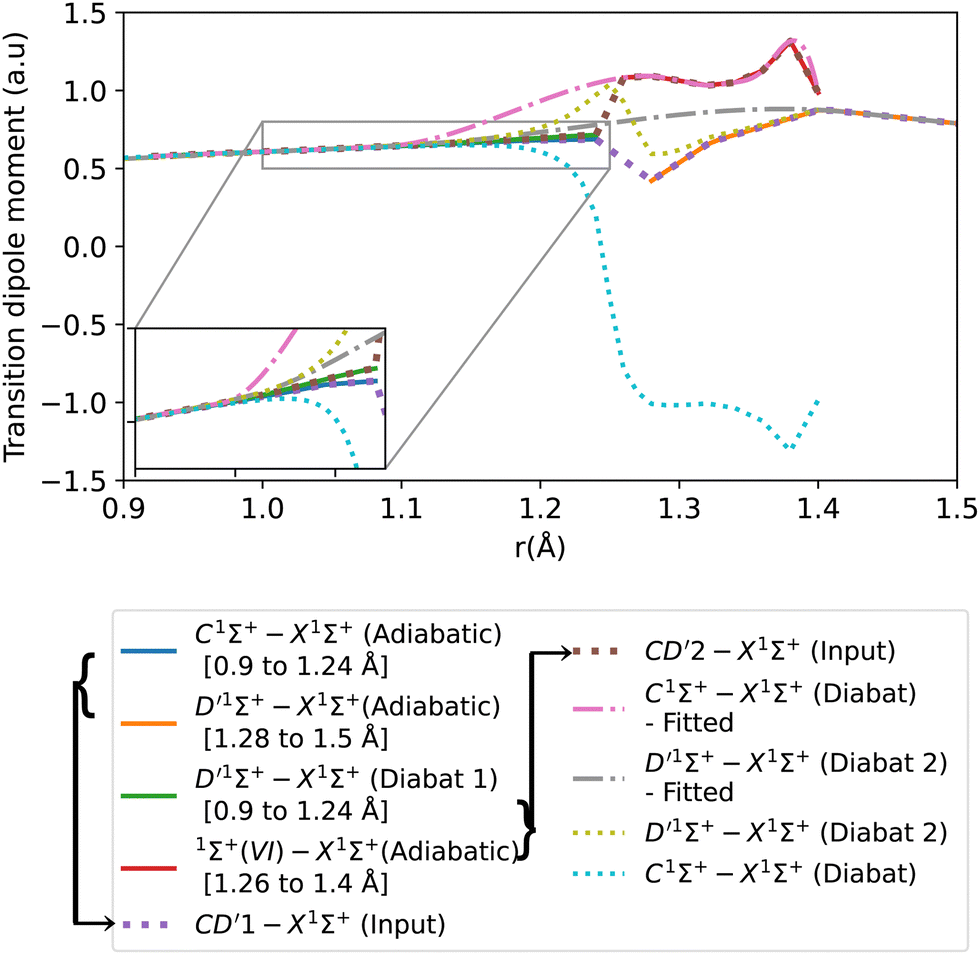 | ||
| Fig. 8 Adiabatic and diabatic C1Σ+–X1Σ+ transition dipole moment curves. D′1Σ+–X1Σ+ (Diabat 1) denotes the D′1Σ+–X1Σ+ diabatic curve obtained from treating BD′ system, and D′1Σ+–X1Σ+ (Diabat 2) denotes the D′1Σ+–X1Σ+ diabatic curve obtained from treating CD′ system. | ||
After the diabatization process, two diabatic TDMCs are obtained, C1Σ+–X1Σ+ and D′1Σ+–X1Σ+. The diabatized CD′ system is denoted Diabat 2. Here, the D′1Σ+ state was used as a tool to facilitate the diabatization process. The diabatic C1Σ+–X1Σ+ curve flipped polarity with respect to the CD′2–X1Σ+ input (associated with the upper diabat), while the D′1Σ+–X1Σ+ (Diabat 2) curve followed the same polarity as the CD′1–X1Σ+ input (associated with the lower diabat), as expected in the 2-level system. Similar behavior was noticed by Brady et al.70 Since we are dealing with a 3-level system (composed of D′1Σ+, C1Σ+ and 1Σ+(VI) states) in reality, we corrected the polarity of the diabatic C1Σ+–X1Σ+ curve by flipping its sign and allowing it to follow the polarity of the CD′2–X1Σ+ curve (associated with the upper diabat). Then the diabatic C1Σ+–X1Σ+ TDM used in the calculation is smoothed using cubic splines with σr = 0.096 a.u., after the diabatization procedure. Similarly to the previously discussed cases, the D′1Σ+–X1Σ+ curve (Diabat 2) obtained directly from the diabatization process exhibits a jump at the avoided crossing, possibly due to numerical errors arising from the simplification of the 3-level system to a 2-level system. Therefore, the curve was also smoothed out using cubic splines with σr = 0.067 a.u., denoted D′1Σ+–X1Σ+ (Diabat 2)-fitted. The relative intensity of the diabatic C1Σ+–X1Σ+ bands, which is the ratio of the first two bands intensities, is 0.034, which agrees well with the experimental values of Imhof et al.94 (RI = 0.029), and Chan et al.95 (RI = 0.031).
3.3 Rovibronic calculations
In this section, we evaluate the accuracy of the diabatic states and corresponding transitions obtained in the previous section, through spectral comparisons with the literature. At the same time, the CO total internal partition functions (TIPS) comparison with the values of Gamache et al.102 and Barklem and Collet103 with the absolute difference for each dataset [QThiswork–QRef], is shown in the ESI,† Section S1. Our data agree well with the TIPS values of Gamache et al.102 with a maximum relative error percentage of 1.328% at 9000 K, which corresponds to an absolute difference of −160.772. Barklem and Collet103 data also agreed well with our data with a maximum relative error percentage of 2.137% at 9000 K, corresponding to an absolute difference of −260.772.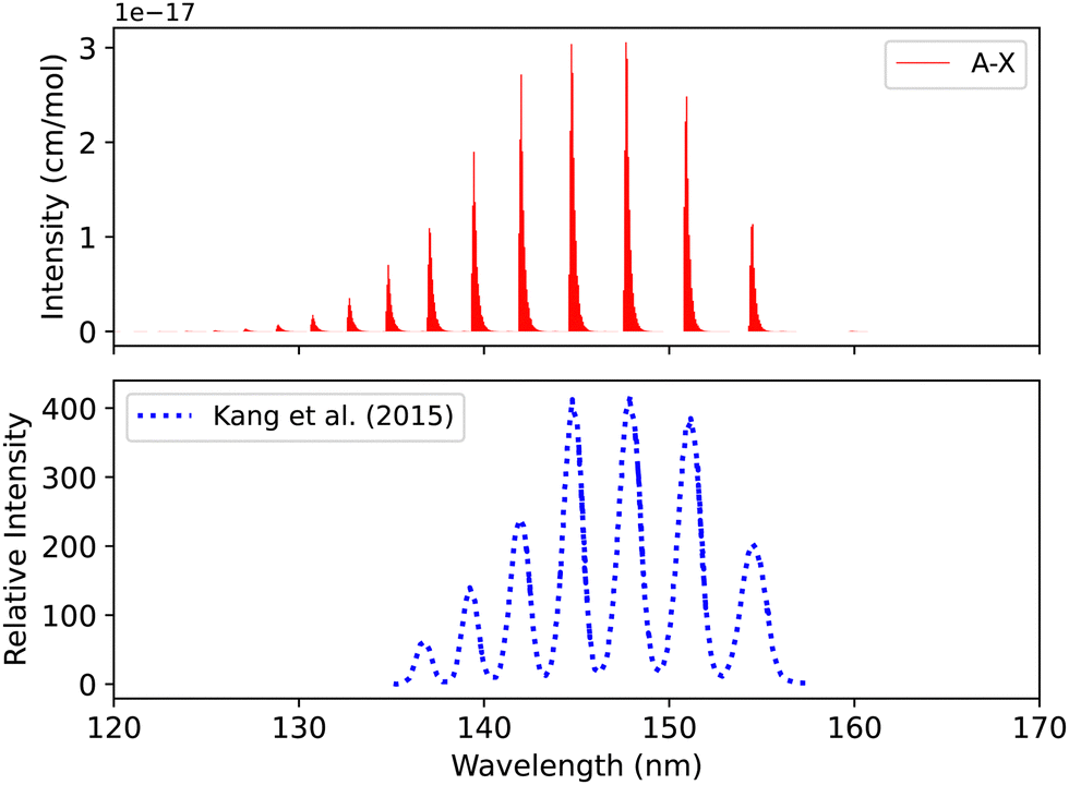 | ||
| Fig. 9 Spectrum of A1Π–X1Σ+ band: upper plot, our calculation; lower plot, experiment of Kang et al.104 | ||
The synthetic spectra obtained were also compared with the simulated normal-mode far ultraviolet spectra of the Mars airglow observed by MAVEN during a periapsis limb observation at 110 km tangent altitude. The normal mode was developed using imaging performance and radiometric response curves with atmospheric models to predict the instrument response,105 see Fig. 10. The first five bands coincide with the MAVEN IUVS peaks. The peak at 152.9 nm most probably corresponds to C II, while the one at 141.2 nm is likely associated with N I. This identification was made using NIST.82 Additionally, the 149.3, 146.3, and 145.2 nm peaks originate from C I emissions.18 The spectrum was calculated at 200 K and 0.008 bar (Fig. 10). There is good agreement with the observations regarding line position and intensity profile with a line position difference of (0.002 < Δλ < 0.25 nm) for the first five peaks for the simulated spectra.
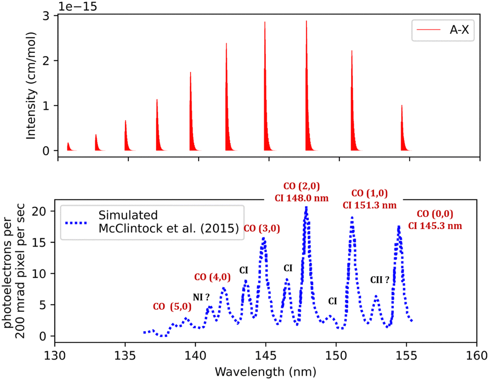 | ||
| Fig. 10 Fourth positive band system spectra of CO: upper plot, our simulation; lower plot, observed far ultraviolet spectrum of the Mars airglow observed by MAVEN during a periapsis limb observation with 110 km tangent altitude.105 | ||
Fig. 11 shows a total experimental spectrum measured by Ajello et al.,18 using electron-impact-fluorescence. The gas pressure was set to 9.066 × 10⁻⁹ bar and at a temperature of 300 K. The comparison was made with the spectrum generated at 30 eV electron energy. The experimental setup consists of Mars Atmosphere and Volatile EvolutioN (MAVEN) mission imaging ultraviolet spectrograph optical engineering unit and an electron gun inside a large vacuum chamber. The line position difference between the experimental and our simulation is (0.0007 < Δλ < 0.3 nm) for the first five peaks.
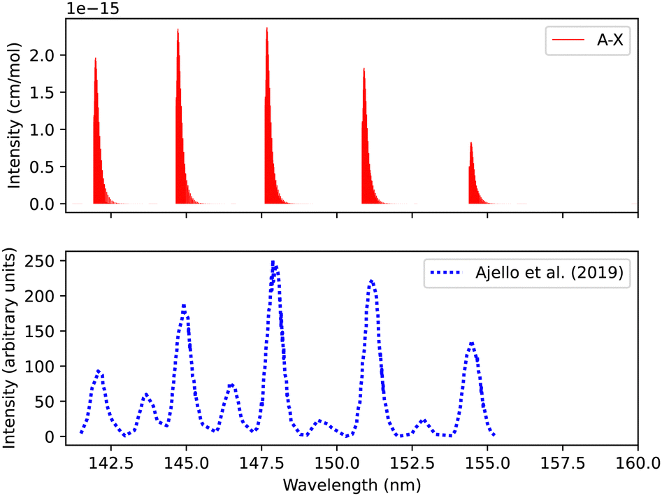 | ||
| Fig. 11 Spectrum of A1Π–X1Σ+ transition: upper plot, our calculations; lower plot, experiments due to Ajello et al.18 | ||
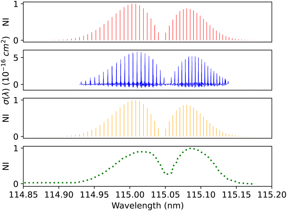 | ||
| Fig. 12 B1Σ+–X1Σ+ (0–0) spectrum: top panel, synthetic band calculated at Eidelsberg et al.41 experimental conditions. Second panel, calibration (0–0) band due to Eidelsberg et al.41 Third panel, synthetic band calculated at Federman et al.106 experimental conditions. Bottom panel, (0–0) band due to Federman et al.106 NI denotes normalized intensity. | ||
Federman et al.106 conducted an experiment using synchrotron radiation to measure the transmission spectra of the B1Σ+–X1Σ+ (0–0) and B1Σ+–X1Σ+ (1–0) bands. The average simulation temperature was set to 275 K because the temperature range in the experiment is between 250 K and 300 K. The pressure was set to 4 × 10⁻⁶ bar for the B1Σ+–X1Σ+ bands to match the experimental conditions. The uncertainty in pressure is (5%), and (1%) in the excitation temperature. The line position difference for the (0–0) band is (0.001 < Δλ < 0.018 nm) (Fig. 12), and (0.01 < Δλ < 0.017 nm) for (1–0) band (Fig. 13).
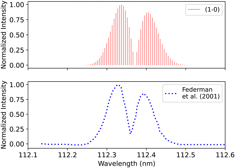 | ||
| Fig. 13 B1Σ+–X1Σ+ (1–0) spectrum: upper plot, synthetic band; lower plot, (1–0) band due to Federman et al.106 | ||
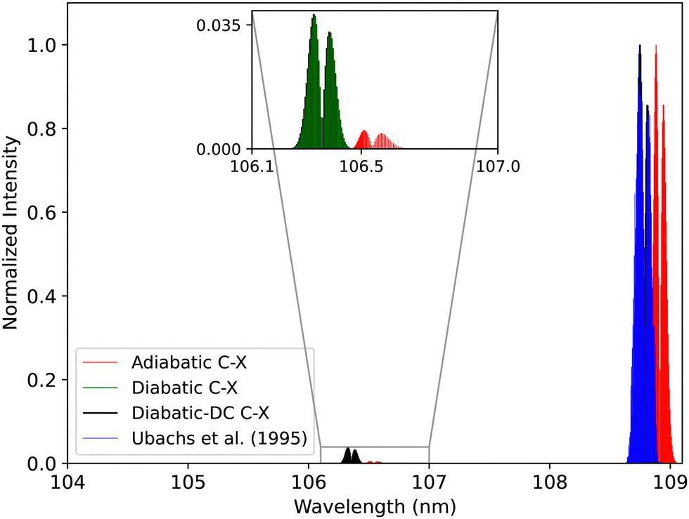
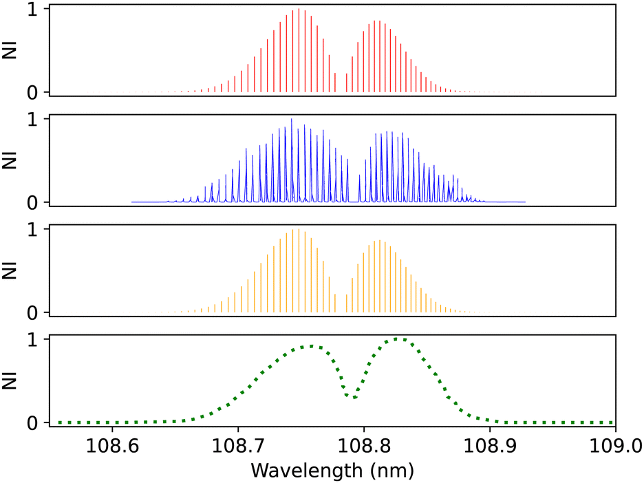 | ||
| Fig. 14 C1Σ+–X1Σ+ (0–0) spectrum: top panel, synthetic band calculated at Ubachs et al.107 experimental conditions. Second panel, calibration (0–0) band due to Ubachs et al.107 Third panel, synthetic band calculated at Federman et al.106 experimental conditions. Bottom panel, (0–0) band due to Federman et al.106 NI denotes normalized intensity. | ||
Federman et al.106 also measured the transmission spectra of C1Σ+–X1Σ+ (0–0) and C1Σ+–X1Σ+ (1–0) bands at 275 K. The pressure for the (0–0) band (Fig. 14) is set to 8 × 10⁻⁷ bar and for the (1–0) band, to 4 × 10⁻⁶ bar. The line position difference of the (0–0) band is (0.01 < Δλ < 0.013 nm). They found that the signal-to-noise ratio for the (1–0) band is lower than that of (0–0), and the quality of the fit is offset to 1.03 compared to the quality of the fit for (0–0), 1.02. According to Federman et al.106 the fitting quality reflects the difference between the observed spectrum and the least-squares fitting process conducted using the line wavelength positions identified in Tilford and Simmons108 study. The higher noise in this case is because the LiF cutoff is near the band position, and this might be one of the reasons for having a slight difference to our synthetic band, (Fig. 15), (Δλ < 0.05 nm).
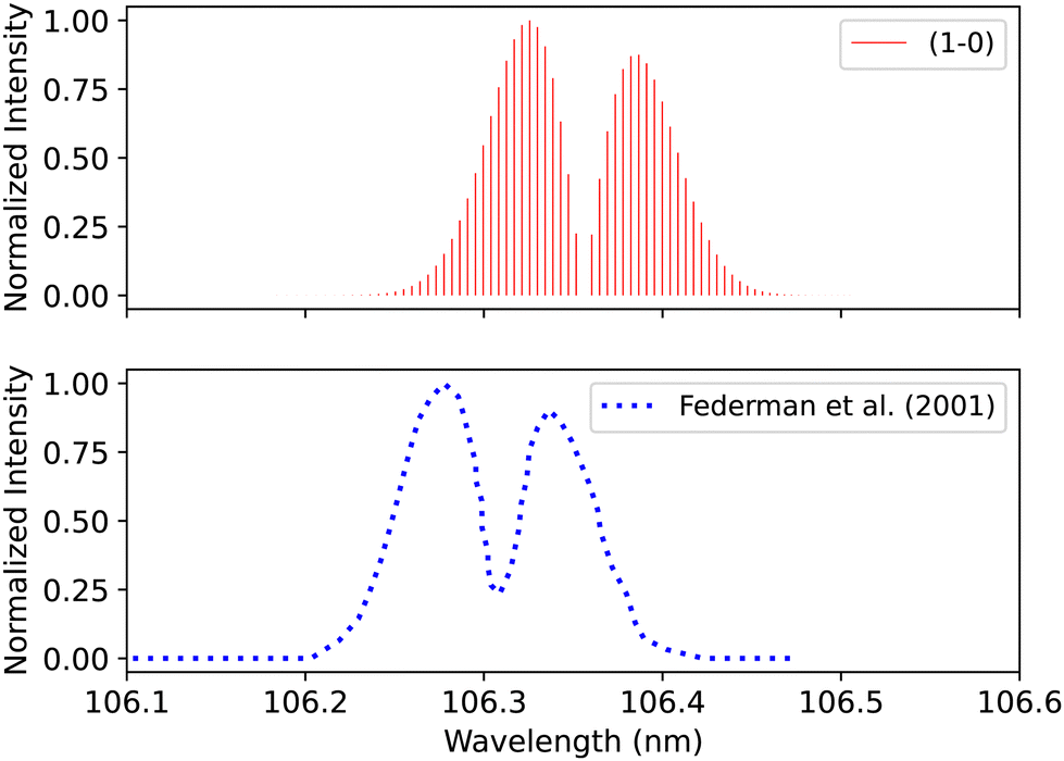 | ||
| Fig. 15 C1Σ+–X1Σ+ (1–0) synthetic band compared with the (1–0) band measured by Federman et al.106 | ||
Lemaire et al.109 recorded the spectra of E1Π–X1Σ+ transition using a Fourier-transform spectrometer connected to SOLEIL synchrotron, which provides resolving power up to 106 in the energy range between 8 to 13 eV. The overall uncertainty in the line position is 0.01 cm−1. The spectrum for the (0–0) band was measured at 295 K after using Cacciani and Ubachs,100 Cacciani et al.,110 Daprà et al.111 bands as calibration peaks in order to reduce the possible source of error, which is associated with the calibration of the wavenumber scale by a small number of atomic transitions. The accuracy of the rotational line position depends on the absolute frequency calibration of the atomic lines and the spectral resolution and the strength of each line measured. Our adiabatic spectrum is calculated at 250 K and 1 bar pressure and is shifted by around 0.05 nm to the shorter wavelengths, see Fig. 16. This shift is probably due to the exclusion of the non-adiabatic couplings, and diagonal BO correction (DBOC) in the adiabatic representation, as discussed in the numerical equivalence of diabatic and adiabatic representations in the CH molecule by Brady et al.69
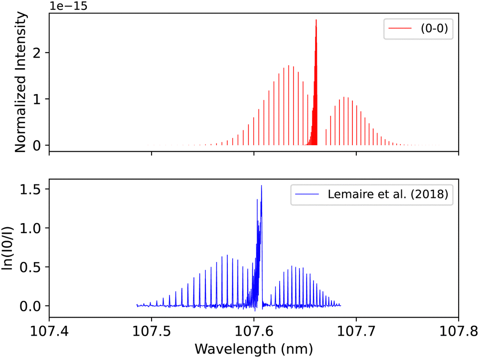 | ||
| Fig. 16 E1Π–X1Σ+ (0–0) synthetic band compared with the (0–0) band measured by Lemaire et al.109 | ||
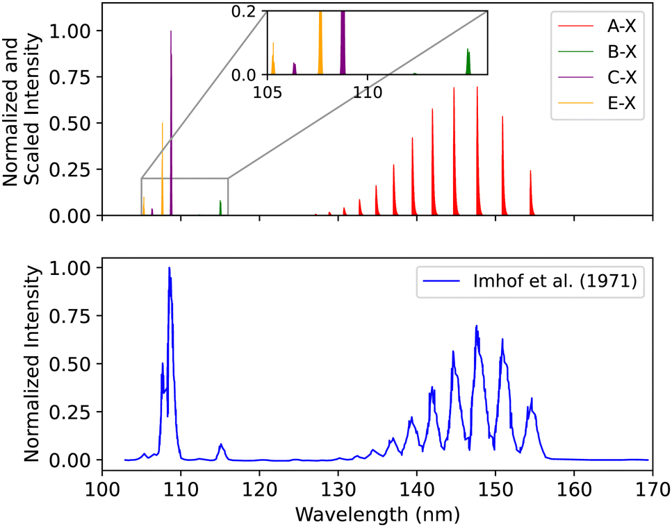 | ||
| Fig. 17 Spectral comparison of the A1Π–X1Σ+, B1Σ+–X1Σ+, C1Σ+–X1Σ+ and E1Π–X1Σ+ bands with the experiment of Imhof et al.94 | ||
Finally, Chan et al.95 used a high-resolution (0.048 eV FWHM) dipole (e, e) spectrometer to record the electron energy loss spectrum from 7 to 20.3 eV energy regime. The uncertainty in the experimental absolute optical oscillator strengths is 5% for the resolved peaks in the spectrum.
The energy shift for the first seven bands of the A1Π–X1Σ+ transition is 0.007 < Δλ < 0.13 nm. For the first two peaks of the B1Σ+–X1Σ+ transition it is 0.015 < Δλ < 0.054 nm, for C1Σ+–X1Σ+ it is 0.007 < Δλ < 0.042 nm, and for E1Π–X1Σ+ 0.005 < Δλ < 0.05 nm (see ESI,† Section S3 and Fig. S2).
3.4 The effect of diabatization on the synthetic spectra
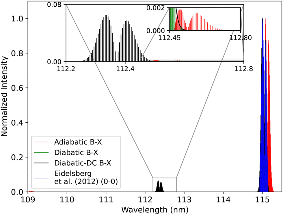 | ||
| Fig. 18 Comparison between the adiabatic and diabatic representations of the B1Σ+–X1Σ+ band system, and with Eidelsberg et al.112 experiment. | ||
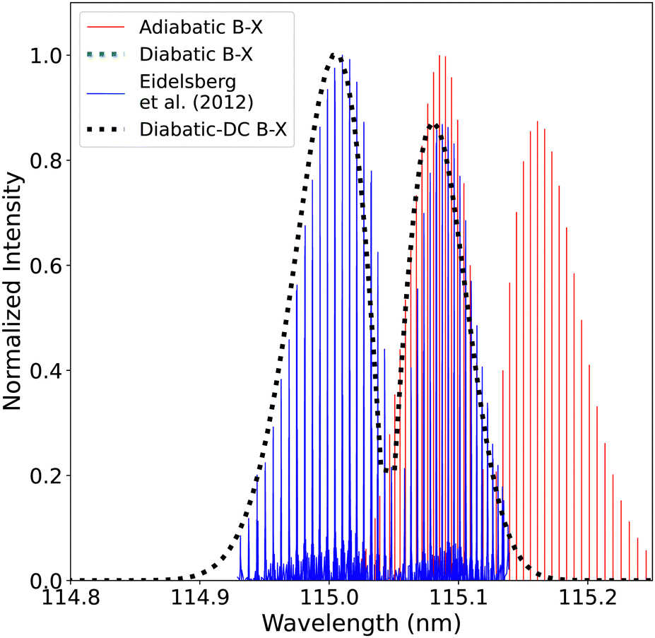 | ||
| Fig. 19 Comparison between the adiabatic and diabatic representations of the (0–0) band of B1Σ+–X1Σ+ band system and with Eidelsberg et al.112 experiment. | ||
The adiabatic peaks generally have lower intensity than the diabatic ones because of the repulsive character of the adiabatic potential energy curves after the adiabatic barrier. This repulsive character is due to tunneling into the continuum region after the adiabatic barrier. Certain energy levels are “stolen” or absent beyond the adiabatic barrier, and this causes intensity reduction; hence, the repulsive effect. This issue of intensity reduction can be solved by including NACs in the adiabatic representation or using the diabatic representation.70 The spectra obtained using the DCs in the diabatic representation almost overlap with that of the diabatic without the DCs since the value of the diabatic coupling is very small with a maximum value of 0.0124 cm−1. The regions of low intensity are sensitive and highly affected by the ab initio results and the profile of the couplings between the diabatic and the adiabatic representation.74
 | ||
| Fig. 20 Comparison between the adiabatic and diabatic representations of the C1Σ+–X1Σ+ band system and with Ubachs et al.107 experiment. | ||
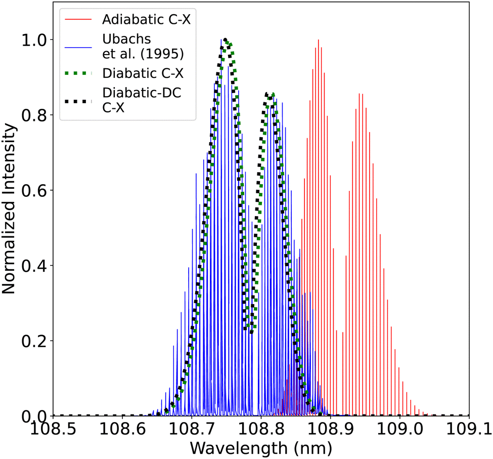 | ||
| Fig. 21 Comparison between the adiabatic and diabatic representations of the (0–0) C1Σ+–X1Σ+ band and with Ubachs et al.107 experiment. | ||
4 Conclusions
In summary, we present accurate potential energy curves for the ground and excited electronic states of CO, which were obtained by employing the CASSCF/MRCI+Q method with the aug-cc-pV5Z basis set. Our calculations yield spectroscopic constants exhibiting remarkable consistency with experimental values. The diabatic model is much better than an adiabatic model without non-adiabatic couplings; its use gives enhanced accuracy of line positions and intensities.To validate our theoretical findings, we have compared the synthetic absorption spectra A1Π–X1Σ+, B1Σ+–X1Σ+, C1Σ+–X1Σ+, D′1Σ+–X1Σ+ and E1Π–X1Σ+ with the existing experimental spectra documented in the literature. We note that, unlike several of the experimental studies with which we compare, our calculations give absolute transition intensities. The high-resolution spectra presented in this paper can be used in forward and general circulation models to calculate the molecule's abundance in planetary atmospheres. Retrieving the molecular densities is essential in understanding the properties of the planetary atmosphere.
Our potential energy and transition dipole moment curves alongside a MARVEL (Measured Active Rotation Vibration Energy Levels)113 study of the rovibronic transitions of CO, which is currently nearing completion,114,115 will be used to generate an ExoMol-style81 hot line list for CO. These curves can also be used as the basis of a study of temperature-dependent photodissociation rates116 and predissociation effects.117,118
Data availability
Sample data/input files from this work are available in the ESI,† named Supplementary Information.pdf and Supplementary Information.zip. The ESI† complements the main paper by providing additional details and data pertinent to the study. Supplementary Information.pdf encompasses the following datasets: partition function (S1): this section presents a comparison of CO partition functions with values sourced from references, providing a comprehensive overview. Spectral comparisons (S2): a comparative analysis of spectra for A–X, B–X, C–X, and E–X transitions, compared with experimental data sourced from Chan et al. Supplementary Information.zip includes: (1) sample Duo input files corresponding to all the transitions mentioned in the text, at different temperature and pressure conditions (.inp format). (2) A sample ExoCross input file of the A–X transition (.inp format). (3) Grids of the PECs and TDMCs as extracted from the MOLPRO output (.csv format). (4) Grids of the original (ab initio) and fitted data (as introduced in Duo) for the A, B, and C states (.csv format). (5) Grids of the stick spectra for all the transitions mentioned in (1) (.xlsx format). (6) Suggested fitting constants for the A, B, and C adiabatic states used in the manuscript (.pdf format). (7) A “read-me” file with more details about all available data. Codes Duo and ExoCross are freely available on the ExoMol github page https://github.com/ExoMol.Conflicts of interest
There are no conflicts to declare.Acknowledgements
Financial support for this work has been provided by Khalifa University of Science and Technology under Award No. CIRA-2019-054 and Aspire Award for Research Excellence (AARE), Award No. 000-329-00001. The Author (N. E. K.) is partly supported by the Khalifa University Space and Planetary Science Center grant (8474000336-KU-SPSC). MG acknowledges partial support by Khalifa University grant #8474000362. Support from the Scientific Computing Department at Khalifa University is gratefully acknowledged. This work was also supported by ERC Advanced Investigator Project 883830 (ExoMolHD).Notes and references
- Y. P. Viala, C. Letzelter, M. Eidelsberg and F. Rostas, Astron. Astrophys., 1988, 193, 265–272 CAS.
- P. M. Solomon and W. Klemperer, Astrophys. J., 1972, 178, 389–422 CrossRef CAS.
- M. H. Bortner, R. H. Kummler and L. S. Jaffe, Water, Air, Soil Pollut., 1974, 3, 17–52 CrossRef CAS.
- R. E. Lupu, P. D. Feldman, H. A. Weaver and G.-P. Tozzi, Astrophys. J., 2007, 670, 1473 CrossRef CAS.
- P. D. Feldman, H. A. Weaver and E. B. Burgh, Astrophys. J., 2002, 576, L91 CrossRef CAS.
- A. Vandaele, A. Mahieux, S. Chamberlain, B. Ristic, S. Robert, I. Thomas, L. Trompet, V. Wilquet and J. Bertaux, Icarus, 2016, 272, 48–59 CrossRef CAS.
- R. Clancy, D. Muhleman and B. Jakosky, Icarus, 1983, 55, 282–301 CrossRef CAS.
- A. A. Penzias, P. M. Solomon, K. B. Jefferts and R. W. Wilson, Astrophys. J., Lett., 1972, 174, L43 CrossRef CAS.
- H. Olofsson, P. Bergman, K. Eriksson and B. Gustafsson, Astron. Astrophys., 1996, 311, 587–615 CAS.
- Q. M. Konopacky, T. S. Barman, B. A. Macintosh and C. Marois, Science, 2013, 339, 1398–1401 CrossRef CAS PubMed.
- J.-M. Désert, A. Lecavelier des Etangs, G. Hébrard, D. K. Sing, D. Ehrenreich, R. Ferlet and A. Vidal-Madjar, Astrophys. J., 2009, 699, 478–485 CrossRef.
- P. Giacobbe, M. Brogi and S. Gandhi, et al. , Nature, 2021, 592, 205–208 CrossRef CAS PubMed.
- A. W. Mantz and J.-P. Maillard, J. Mol. Spectrosc., 1974, 53, 466–478 CrossRef CAS.
- M. Zhang and D. Shi, Comput. Theor. Chem., 2021, 1202, 113302 CrossRef CAS.
- Y. Du, K. Tamura, S. Moore, Z. Peng, T. Nozaki and P. J. Bruggeman, Plasma Chem. Plasma Process., 2017, 37, 29–41 CrossRef CAS.
- S. D. McGuire, A. C. Tibere-Inglesse, P. B. Mariotto, B. A. Cruden and C. O. Laux, J. Quant. Spectrosc. Radiat. Transfer, 2020, 245, 106855 CrossRef CAS.
- S. Yamada, Y. Morita, A. Nezu and H. Akatsuka, Jpn. J. Appl. Phys., 2021, 60, 046005 CrossRef CAS.
- J. M. Ajello, C. P. Malone, J. S. Evans, G. M. Holsclaw, A. C. Hoskins, S. K. Jain, W. E. McClintock, X. Liu, V. Veibell, J. Deighan, J.-C. Gérard, D. Y. Lo and N. Schneider, J. Geophys. Res.: Space Phys., 2019, 124, 2954–2977 CrossRef.
- F. H. Lootah, J. Deighan, M. Fillingim, S. Jain, J. S. Evans, H. Al Matroushi, M. Chaffin, G. Holsclaw, R. Lillis, H. Al Mazmi, J. Correira and S. England, Geophys. Res. Lett., 2022, 49, e2022GL099852 CrossRef CAS.
- R. J. Glinski, J. A. Nuth III, M. D. Reese and M. L. Sitko, Astrophys. J., 1996, 467, L109 CrossRef CAS.
- Y. Li, R. Buenker and G. Hirsch, Theor. Chem. Acc., 1998, 100, 112–116 Search PubMed.
- D. Y. Lo, R. V. Yelle, R. J. Lillis and J. I. Deighan, Icarus, 2021, 360, 114371 CrossRef CAS.
- D. Y. Lo, R. V. Yelle, J. I. Deighan, S. K. Jain, J. S. Evans, M. H. Stevens, J. M. Ajello, M. A. Mayyasi and N. M. Schneider, Icarus, 2022, 371, 114664 CrossRef CAS.
- T. Yoshida, S. Aoki, Y. Ueno, N. Terada, Y. Nakamura, K. Shiobara, N. Yoshida, H. Nakagawa, S. Sakai and S. Koyama, Planet. Sci. J., 2023, 4, 53 CrossRef CAS.
- D. J. Strickland, J. Bishop, J. S. Evans, T. Majeed, P. M. Shen, R. J. Cox, R. Link and R. E. Huffman, J. Quant. Spectrosc. Radiat. Transfer, 1999, 62, 689–742 CrossRef CAS.
- L. Rothman, I. Gordon, R. Barber, H. Dothe, R. Gamache, A. Goldman, V. Perevalov, S. Tashkun and J. Tennyson, J. Quant. Spectrosc. Radiat. Transfer, 2010, 111, 2139–2150 CrossRef CAS.
- L. S. Rothman, Nat. Rev. Phys., 2021, 3, 302–304 CrossRef.
- J. Tennyson, S. N. Yurchenko, A. F. Al-Refaie, V. H. J. Clark, K. L. Chubb, E. K. Conway, A. Dewan, M. N. Gorman, C. Hill, A. E. Lynas-Gray, T. Mellor, L. K. McKemmish, A. Owens, O. L. Polyansky, M. Semenov, W. Somogyi, G. Tinetti, A. Upadhyay, I. Waldmann, Y. Wang, S. Wright and O. P. Yurchenko, J. Quant. Spectrosc. Radiat. Transfer, 2020, 255, 107228 CrossRef CAS.
- V. V. Meshkov, A. Y. Ermilov, A. V. Stolyarov, E. S. Medvedev, V. G. Ushakov and I. E. Gordon, J. Quant. Spectrosc. Radiat. Transfer, 2022, 280, 108090 CrossRef CAS.
- J. Luque and D. R. Crosley, J. Chem. Phys., 1999, 111, 7405–7415 CrossRef CAS.
- Q. Qu, S. N. Yurchenko and J. Tennyson, Mon. Not. R. Astron. Soc., 2021, 504, 5768–5777 CrossRef CAS.
- D. M. Cooper and S. R. Langhoff, J. Chem. Phys., 1981, 74, 1200–1210 CrossRef CAS.
- D. L. Cooper and K. P. Kirby, J. Chem. Phys., 1987, 87, 424–432 CrossRef CAS.
- D. L. Cooper and K. P. Kirby, Chem. Phys. Lett., 1988, 152, 393–396 CrossRef CAS.
- K. Kirby and D. L. Cooper, J. Chem. Phys., 1989, 90, 4895–4902 CrossRef CAS.
- M. Eidelsberg, J.-Y. Roncin, A. Le Floch, F. Launay, C. Letzelter and J. Rostas, J. Mol. Spectrosc., 1987, 121, 309–336 CrossRef CAS.
- G. L. Wolk and J. W. Rich, J. Chem. Phys., 1983, 79, 12–18 CrossRef CAS.
- W. Coughran, J. Rose, T.-I. Shibuya and V. McKoy, J. Chem. Phys., 1973, 58, 2699–2709 CrossRef.
- W.-U. L. Tchang-Brillet, P. S. Julienne, J. M. Robbe, C. Letzelter and F. Rostas, J. Chem. Phys., 1992, 96, 6735–6745 CrossRef CAS.
- G. J. Vázquez, J. M. Amero, H. P. Liebermann and H. Lefebvre-Brion, J. Phys. Chem. A, 2009, 113, 13395–13401 CrossRef PubMed.
- M. Eidelsberg, F. Launay, K. Ito, T. Matsui, P. C. Hinnen, E. Reinhold, W. Ubachs and K. P. Huber, J. Chem. Phys., 2004, 121, 292–308 CrossRef CAS PubMed.
- H. Lefebvre-Brion and B. R. Lewis, Mol. Phys., 2007, 105, 1625–1630 CrossRef CAS.
- J. Baker, Chem. Phys. Lett., 2005, 408, 312–316 CrossRef CAS.
- K. P. Huber and G. Herzberg, Molecular Spectra and Molecular Structure. IV. Constants of Diatomic Molecule, Springer, Boston, MA, 1979, pp. 1–716 Search PubMed.
- P.-F. Lu, L. Yan, Z.-Y. Yu, Y.-F. Gao and T. Gao, Commun. Theor. Phys., 2013, 59, 193 CrossRef CAS.
- J. Cheng, H. Zhang and X. Cheng, Astrophys. J., 2018, 859, 19 CrossRef.
- K. Bielska, A. A. Kyuberis, Z. D. Reed, G. Li, A. Cygan, R. Ciuryło, E. M. Adkins, L. Lodi, N. F. Zobov, V. Ebert, D. Lisak, J. T. Hodges, J. Tennyson and O. L. Polyansky, Phys. Rev. Lett., 2022, 129, 043002 CrossRef CAS PubMed.
- A. A. Balashov, K. Bielska, G. Li, A. A. Kyuberis, S. Wójtewicz, J. Domysławska, R. Ciuryło, N. F. Zobov, D. Lisak, J. Tennyson and O. L. Polyansky, J. Chem. Phys., 2023, 158, 234306 CrossRef CAS PubMed.
- H.-J. Werner, P. J. Knowles, F. R. Manby, J. A. Black, K. Doll, A. Heßelmann, D. Kats, A. Köhn, T. Korona, D. A. Kreplin, Q. Ma, T. F. Miller, A. Mitrushchenkov, K. A. Peterson, I. Polyak, G. Rauhut and M. Sibaev, J. Chem. Phys., 2020, 152, 144107 CrossRef CAS PubMed.
- A. Moussa, N. El-Kork, I. Zeid, E. Salem and M. Korek, ACS Omega, 2022, 7, 18577–18596 CrossRef CAS PubMed.
- W. Chmaisani, N. El-Kork, S. Elmoussaoui and M. Korek, ACS Omega, 2019, 4, 14987–14995 CrossRef CAS PubMed.
- M. Korek, N. El-Kork, A. Moussa and A. Bentiba, Chem. Phys. Lett., 2013, 575, 115–121 CrossRef CAS.
- S. Elmoussaoui, N. El-Kork and M. Korek, Comput. Theor. Chem., 2016, 1090, 94–104 CrossRef CAS.
- A. Dora, J. Tennyson and K. Chakrabarti, Eur. Phys. J. D, 2016, 70, 1–10 CrossRef CAS.
- L. A. Terrabuio, N. A. da Silva, R. L. A. Haiduke and C. F. Matta, Mol. Phys., 2017, 115, 1955–1965 CrossRef CAS.
- B. P. Pritchard, D. Altarawy, B. Didier, T. D. Gibson and T. L. Windus, J. Chem. Inf. Model., 2019, 59, 4814–4820 CrossRef CAS PubMed.
- T. H. Dunning Jr, J. Chem. Phys., 1989, 90, 1007–1023 CrossRef.
- R. A. Kendall, T. H. Dunning Jr and R. J. Harrison, J. Chem. Phys., 1992, 96, 6796–6806 CrossRef CAS.
- D. Koch, Y. Chen, P. Golub and S. Manzhos, Phys. Chem. Chem. Phys., 2019, 21, 20814–20821 RSC.
- D. R. Yarkony, Rev. Mod. Phys., 1996, 68, 985–1013 CrossRef CAS.
- J. v Neumann and E. Wigner, in On the behaviour of eigenvalues in adiabatic processes-Quantum Chemistry: Classic Scientific Papers, ed. H. Hettema, World Scientific, 2000, pp. 25–31 Search PubMed.
- C. A. Mead and D. G. Truhlar, J. Chem. Phys., 1982, 77, 6090–6098 CrossRef CAS.
- A. W. Jasper, B. K. Kendrick, C. Alden Mead and D. G. Truhlar, in Non-Born-Oppenheimer chemistry: Potential surfaces, couplings, and dynamics-Modern Trends In Chemical Reaction Dynamics: Part I: Experiment and Theory, ed. X. Yang and K. Liu, World Scientific, 2004, pp. 329–391 Search PubMed.
- T. Karman, M. Besemer, A. van der Avoird and G. C. Groenenboom, J. Chem. Phys., 2018, 148, 094105 CrossRef.
- Y. Shu, Z. Varga, A. G. Sampaio de Oliveira-Filho and D. G. Truhlar, J. Chem. Theory Comput., 2021, 17, 1106–1116 CrossRef CAS PubMed.
- C. A. Mead and D. G. Truhlar, J. Chem. Phys., 1982, 77, 6090–6098 CrossRef CAS.
- J. B. Delos, Rev. Mod. Phys., 1981, 53, 287–357 CrossRef CAS.
- X. Yang and K. Liu, Modern Trends in Chemical Reaction Dynamics, World Scientific, 2004 Search PubMed.
- R. P. Brady, C. Drury, S. N. Yurchenko and J. Tennyson, J. Chem. Theory Comput., 2024, 20, 2127–2139 CrossRef CAS PubMed.
- R. P. Brady, S. N. Yurchenko, G.-S. Kim, W. Somogyi and J. Tennyson, Phys. Chem. Chem. Phys., 2022, 24, 24076–24088 RSC.
- H. An and K. K. Baeck, J. Chem. Phys., 2015, 143, 194102 CrossRef PubMed.
- A. J. C. Varandas, J. Chem. Phys., 2009, 131, 124128 CrossRef CAS PubMed.
- A. J. C. Varandas, J. Chem. Phys., 2011, 135, 119902 CrossRef.
- S. N. Yurchenko, L. Lodi, J. Tennyson and A. V. Stolyarov, Comput. Phys. Commun., 2016, 202, 262–275 CrossRef CAS.
- J. Tennyson and S. N. Yurchenko, Int. J. Quantum Chem., 2017, 117, 92–103 CrossRef CAS.
- E. G. Lee, J. Y. Seto, T. Hirao, P. F. Bernath and R. J. Le Roy, J. Mol. Spectrosc., 1999, 194, 197–202 CrossRef CAS PubMed.
- D. Hyams, CurveExpert, https://www.curveexpert.net/, 2009–2021, [Computer Software].
- M. Semenov, N. El-Kork, S. N. Yurchenko and J. Tennyson, Phys. Chem. Chem. Phys., 2021, 23, 22057–22066 RSC.
- OriginLab Corporation, OriginPro, Accessed 2023, https://www.originlab.com/origin, Software. Available online at https://www.originlab.com/origin..
- S. N. Yurchenko, A. F. Al-Refaie and J. Tennyson, Astron. Astrophys., 2018, 614, A131 CrossRef.
- J. Tennyson, S. N. Yurchenko, J. Zhang, C. A. Bowesman, R. P. Brady, J. Buldyreva, K. L. Chubb, R. R. Gamache, M. N. Gorman, E. R. Guest, C. Hill, K. Kefala, A. E. Lynas-Gray, T. M. Mellor, L. K. McKemmish, G. B. Mitev, I. I. Mizus, A. Owens, Z. Peng, A. N. Perri, M. Pezzella, O. L. Polyansky, Q. Qu, M. Semenov, O. Smola, A. Solokov, W. Somogyi, A. Upadhyay, S. O. M. Wright and N. F. Zobov, J. Quant. Spectrosc. Radiat. Transfer, 2024, 326, 109083 CrossRef CAS.
- A. Kramida, Y. Ralchenko, J. Reader and N. A. Team, NIST Atomic Spectra Database (version 5.10), [Online], 2022, https://physics.nist.gov/asd, [Accessed on Tue Apr 04 2023] Search PubMed.
- G. Herzberg, Molecular Spectra and Molecular Structure I: Spectra of Diatomic Molecules, Krieger Publishing Company, 1989 Search PubMed.
- N. Abu el kher, I. Zeid, N. El-Kork and M. Korek, J. Comput. Sci., 2021, 51, 101264 CrossRef.
- L. Chantranupong, K. Bhanuprakash, M. Honigmann, G. Hirsch and R. J. Buenker, Chem. Phys., 1992, 161, 351–362 CrossRef CAS.
- D.-H. Shi, W.-T. Li, J.-F. Sun and Z.-L. Zhu, Int. J. Quantum Chem., 2013, 113, 934–942 CrossRef CAS.
- J. A. Hall, J. Schamps, J. M. Robbe and H. Lefebvre-Brion, J. Chem. Phys., 1973, 59, 3271–3283 CrossRef CAS.
- A. Spielfiedel, W. Ü. Tchang-Brillet, F. Dayou and N. Feautrier, Astron. Astrophys., 1999, 346, 699–704 CAS.
- S. V. O’Neil and H. F. Schaefer, J. Chem. Phys., 1970, 53, 3994–4004 CrossRef.
- M. Majumder, N. Sathyamurthy, H. Lefebvre-Brion and G. J. Vázquez, J. Phys. B: At., Mol. Opt. Phys., 2012, 45, 185101 CrossRef.
- M. Eidelsberg, J. J. Benayoun, Y. Viala, F. Rostas, P. L. Smith, K. Yoshino, G. Stark and C. A. Shettle, Astron. Astrophys., 1992, 265, 839–842 CAS.
- M. Eidelsberg and F. Rostas, Astron. Astrophys., 1990, 235, 472–489 CAS.
- A. Dora and J. Tennyson, J. Phys. B: At., Mol. Opt. Phys., 2020, 53, 195202 CrossRef CAS.
- R. E. Imhof, F. H. Read and S. T. Beckett, J. Phys. B: At. Mol. Phys., 1972, 5, 896 CrossRef CAS.
- W. F. Chan, G. Cooper and C. E. Brion, Chem. Phys., 1993, 170, 123–138 CrossRef CAS.
- Z. Varga, K. A. Parker and D. G. Truhlar, Phys. Chem. Chem. Phys., 2018, 20, 26643–26659 RSC.
- J. E. Subotnik, E. C. Alguire, Q. Ou, B. R. Landry and S. Fatehi, Acc. Chem. Res., 2015, 48, 1340–1350 CrossRef CAS PubMed.
- C. V. V. Prasad, G. L. Bhale and S. P. Reddy, J. Mol. Spectrosc., 1987, 121, 261–269 CrossRef CAS.
- G. Berden, R. T. Jongma, D. van der Zande and G. Meijer, J. Chem. Phys., 1997, 107, 8303–8310 CrossRef CAS.
- P. Cacciani and W. Ubachs, J. Mol. Spectrosc., 2004, 225, 62–65 CrossRef CAS.
- J. Baker, J. Mol. Spectrosc., 2005, 234, 75–83 CrossRef CAS.
- R. R. Gamache, B. Vispoel, M. Rey, A. Nikitin, V. Tyuterev, O. Egorov, I. E. Gordon and V. Boudon, J. Quant. Spectrosc. Radiat. Transfer, 2021, 271, 107713 CrossRef CAS.
- P. S. Barklem and R. Collet, Astron. Astrophys., 2016, 588, A96 CrossRef.
- X. Kang, Y. W. Liu, L. Q. Xu, D. D. Ni, K. Yang, N. Hiraoka, K. D. Tsuei and L. F. Zhu, Astrophys. J., 2015, 807, 96 CrossRef.
- W. E. McClintock, N. M. Schneider, G. M. Holsclaw, J. Deighan, I. Stewart, A. Soto, F. Lefèvre, F. Montmessin, M. Chaffin and A. Stiepen, et al. , Space Sci. Rev., 2015, 195, 75–124 CrossRef.
- S. R. Federman, M. Fritts, S. Cheng, K. M. Menningen, D. C. Knauth and K. Fulk, Astrophys. J., Suppl. Ser., 2001, 134, 133 CrossRef CAS.
- W. Ubachs, P. Hinnen, P. Hansen, S. Stolte, W. Hogervorst and P. Cacciani, J. Mol. Spectrosc., 1995, 174, 388–396 CrossRef CAS.
- S. G. Tilford and J. D. Simmons, J. Phys. Chem. Ref. Data, 1972, 1, 147–188 CrossRef CAS.
- J. L. Lemaire, A. N. Heays, M. Eidelsberg, L. Gavilan, G. Stark, S. R. Federman, J. R. Lyons and N. de Oliveira, Astron. Astrophys., 2018, 614, A114 CrossRef.
- P. Cacciani, W. Hogervorst and W. Ubachs, J. Chem. Phys., 1995, 102, 8308–8320 CrossRef CAS.
- M. Daprà, M. L. Niu, E. J. Salumbides, M. T. Murphy and W. Ubachs, Astrophys. J., 2016, 826, 192 CrossRef.
- M. Eidelsberg, J. L. Lemaire, S. R. Federman, G. Stark, A. N. Heays, Y. Sheffer, L. Gavilan, J.-H. Fillion, F. Rostas, J. R. Lyons, P. L. Smith, N. de Oliveira, D. Joyeux, M. Roudjane and L. Nahon, Astron. Astrophys., 2012, 543, A69 CrossRef.
- T. Furtenbacher, A. G. Császár and J. Tennyson, J. Mol. Spectrosc., 2007, 245, 115–125 CrossRef CAS.
- S. Mahmoud, N. El-Kork, N. Abu Elkher, M. Almehairbi, M. S. Khalil, T. Furtenbacher, O. P. Yurchenko, S. N. Yurchenko and J. Tennyson, Astrophys. J. Suppl., 2025 DOI:10.3847/1538-4365/ada3c9.
- Q.-H. Ni, C. Hill, S. N. Yurchenko, M. Pezzella and A. Z. Fateev, ExoPhoto: A database of temperature dependent photodissociation cross sections, RAS Tech. Instr., 2025 Search PubMed.
- M. Pezzella, S. N. Yurchenko and J. Tennyson, Phys. Chem. Chem. Phys., 2021, 23, 16390–16400 RSC.
- S. N. Yurchenko, W. Szajna, R. Hakalla, M. Semenov, A. Sokolov, J. Tennyson, Y. Pavlenko and M. R. Schmidt, Mon. Not. R. Astron. Soc., 2024, 527, 9736–9756 CrossRef.
- G. B. Mitev, S. N. Yurchenko and J. Tennyson, J. Chem. Phys., 2024, 160, 144110 CrossRef CAS PubMed.
Footnote |
| † Electronic supplementary information (ESI) available. See DOI: https://doi.org/10.1039/d4cp03418j |
| This journal is © the Owner Societies 2025 |