
Effect of concentration gradient on spiral wave dynamics in the Belousov–Zhabotinsky reaction system†
Parvej
Khan
 and
Sumana
Dutta
*
and
Sumana
Dutta
*
Indian Institute of Technology Guwahati, Assam 781039, India. E-mail: sumana@iitg.ac.in
First published on 27th December 2024
Abstract
The oscillatory Belousov–Zhabotinsky (BZ) reaction is often used for the study of rotating spiral waves that are responsible for life-threatening cardiac arrhythmia. In this work, we explore the influence of a concentration gradient on the dynamics of spiral waves in the BZ-reaction system. Using ion-exchange resin beads, we introduce a gradient of hydrogen ions in a thin layer of BZ gel hosting a spiral wave. By monitoring the drift of the spiral tips from their initial position, we show that a gradient of hydrogen-ions can manoeuvre the position of the spiral. The magnitude of the drift is found to depend on the gradient strength and relative position of the spiral from the resin beads. Our experimental study is supported with numerical simulations carried out on a modified Oregonator model that we have developed from the Field, Körös, Noyes mechanism of the BZ.
1. Introduction
Certain chemical and biological systems are host to excitation waves like target, two dimensional (2D) spiral, and three-dimensional (3D) scroll waves. These self-sustained waves are governed by laws of curvature dynamics.1 A concave wavefront is faster than a plane one, and hence, once a spiral is formed in the media, the frequency of its wave arms will surpass those of any regular plane waves in the system.2 This is why, when such a rotating singularity is created in the cardiac system, it becomes an independent pace maker in the heart, leading to tachycardia, or faster heart beats. A further break-up of spiral and scroll waves leading to the formation of many such rotors will result in lethal conditions of atrial and ventricular fibrillation that can result in cardiac arrest.3 Hence, the study and control of these waves is of paramount importance to physicians and scientists alike. It has always been challenging to control the complex spatiotemporal dynamics appearing in such excitable media. Sudden cardiac arrest is often treated with a defibrillator that involves the administering of strong, fast electric shocks. While this may remove the unwanted electrical rotors from the heart, it may sow the seeds of future cardiac arrest. So scientists are on the lookout for milder techniques to control such waves of electrical activity in the heart.4,5Other than the cardiac system, biological systems such as the social amoeba, Dictyostelium discoidium,6 neuronal,7 and retinal8 tissues, and some other nonlinear chemical systems like the Belousov–Zhabotinsky reaction system9 and the catalytic oxidation of CO on Pt,10 sustain spiral and scroll waves. The BZ system, which constitutes the oxidation of an organic acid by sodium bromate, in the presence of sulphuric acid and a metal catalyst with variable oxidation states, is a well known laboratory model for the study of these excitation waves.11 Its chemical kinetics, established by Field, Korös, and Noyes, known as the FKN mechanism, has been able to explain the oscillatory behavior of the system.12 Considering the most important steps in the kinetics of the complicated reaction, the group from Oregon established the mathematical Oregonator model for the BZ system.13 A diffusion coupled Oregonator model can emulate an unstirred layer of the BZ, and is able to show the formation of excitation waves, viz. 2D spiral waves and 3D scroll waves.14,15 Both the BZ and its mathematical model have been extensively used for the study of the control and dynamics of these spiral and scroll waves.11
Previous experimental and theoretical studies have shown that different kinds of external and internal perturbations, like light, noise, electrical potential, electromagnetic field, and thermal gradient, can affect the excitability of a reaction diffusion system.16–19 This can lead to a change in the dynamics of the excitable waves. Spiral waves drift away from their initial position under the influence of electrical and thermal gradients,20–23 while scroll waves align themselves perpendicular to the direction of the gradient.24,25 A vertical CO2 gradient in a closed container of BZ reaction has shown to induce a twist in 3D-scroll waves,26 while spiral rotors drifted under the influence of other high frequency excitation waves.27
In this work, we try to control the dynamics of a spiral wave in the BZ reaction system, by applying a concentration gradient of hydrogen ions. Here, we use ion exchange resin beads to produce a concentration gradient of H+-ions in our two-dimensional reaction system. Increasing H+-ion concentration is known to increase the excitability of the BZ-medium. A homogeneous increase in the concentration of sulphuric acid, and hence [H+], is known to result in a linear increase in the frequency of the spiral, and an exponential decay of the wavelength,28,29 Hence, we expected that a gradient of H+-ions would effect the dynamics of the spiral tips in some way. It remained to be seen if the concentration gradient acted like the external gradients that had already been studied, or the effect was somewhat different. Compared to the strong external gradients used earlier to control spiral and scroll waves, like electric fields and thermal gradients, the concentration gradient used in our study is much weaker and can be internally applied within the system. Our system shows that the spiral drifts under the influence of a gradient of hydrogen ions. If the two tips of the spiral experiences different strengths of the gradient, they can move differently. The amount of drift depends upon the strength of the gradient and the position of the spiral. The usual form of the Oregonator model cannot be used to precisely describe our experimental system, as the H+-ion concentration is not explicit. Hence, we use a modified kinetic model, that we derive from the FKN mechanism. The numerical simulations carried out on this modified Oregonator model corroborates well our experimental results.
2. Experimental methods
We carried out experiments using the BZ reaction system. The reaction mixture was composed of a solution of 0.04 M sodium bromate, 0.04 M malonic acid, 0.2 M sulphuric acid, 0.6 mM ferroin indicator, and agarose (0.8 wt/vol%), in millipore water. The mixture was heated to the melting temperature of the gel, after which it was allowed to cool for about 6 minutes with continuous stirring. Then it was poured into a Petri dish so as to form a layer of 3 mm height. The gel matrix was used in order to avoid convection. A circular wave was generated by dipping the tip of a silver wire for a few seconds at the centre of the dish. This wave was then allowed to expand before it was cleaved manually, to form a pair of counter-rotating spiral waves. The reaction system was monitored with a charged coupled device (CCD) camera (mvBlueFOX 220a) through a blue filter, while it was illuminated from below with a diffused white light. A schematic diagram of the set-up has been given in Fig. 1(a). The images were recorded onto a personal computer at an interval of 2 seconds. The data was analysed with inhouse MATLAB codes. All the experiments were performed at room temperature (22 ± 1 °C).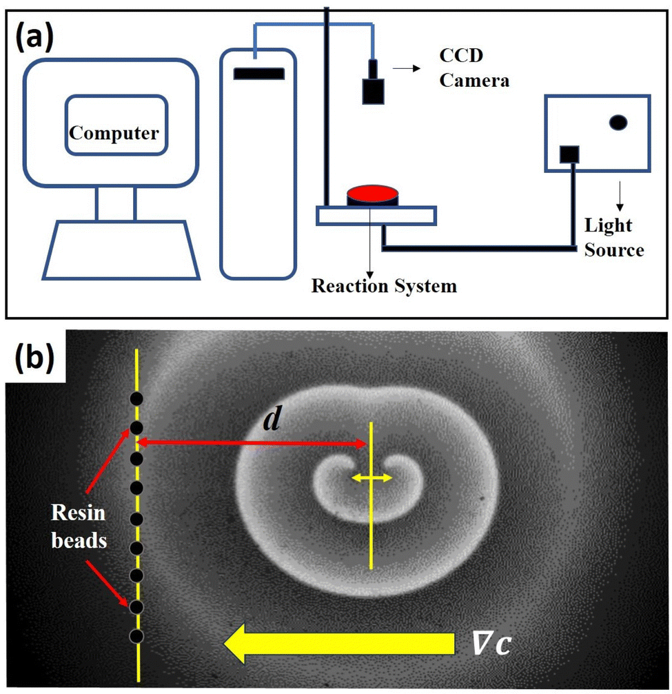 | ||
| Fig. 1 Experimental set up: (a) a schematic of our experimental system, and (b) initial snapshot of a typical experiment, in the presence of a concentration gradient introduced in the form of a column of ion-exchange resin beads (black circles on the left). Area of the snapshot is 2.5 cm × 4.1 cm and d is the distance between the column of beads and the center of the line joining the spiral tips. The direction of concentration gradient (∇c) is shown by an arrow. | ||
To study the effect of a concentration gradient, we introduced hydrogen exchange resin beads, Amberlyst 15 hydrogen form, into the system. This is expected to act as a source of H+-ions. A snapshot of a typical experiment is shown Fig. 1(b). After the initiation of the spiral pair, we allowed it to rotate at least three times before introducing the resin beads, in the form of a straight line, thus creating a gradient of hydrogen ions, that decreases as we move away from the column. All the beads, 0.9 mm in diameter, were kept equidistant from each other within a length (column height) of 3.0 cm. The distance (d) between the line joining the tips of the spirals (before introduction of the beads) and the column of beads was varied to change the gradient strength experienced by the spiral pair.
3. Experimental results
Ion exchange resins appear as solid, insoluble beads, which contain weakly bound ions. They are capable of exchanging these ions when they are in contact with other solutions. Normally, ion exchange resins consist of a matrix of cross-linked polymers with uniformly distributed ion active sites. In our case, we used a cation exchange resin (Amberlyst 15 hydrogen form), which means its matrix is negatively charged and capable of losing or exchanging positive ions (hydrogen ions). In our reaction system, the cations present are Na+ and coordinated Fe2+/3+. Soaking the beads overnight in a solution of the ferroin catalyst did not change their color. We decanted the liquid solution and carried out UV-vis spectrophotometric analysis of the same (Fig. S1 in the ESI†). There was no change in absorption intensity, which proves that neither did the ferroin bind to the resin, nor was the H+-ion exchanged by the Fe2+/3+ of the catalyst.Our column of resin beads on one side of the spiral would create a gradient of hydrogen ion concentration in the medium. Increasing the number of beads would also increase the strength of the gradient. Though the separation distance between the beads in the column, changes with their numbers, however, since the spiral is placed at a larger distance from the beads, the effect of the concentration gradient of protons emanating from the column of resin beads can be considered to be varying only in the horizontal (x) direction.
Fig. 2(a) and (b) show the snapshots from one of our experiments. A visual comparison of the initial (Fig. 2(a)) and final (Fig. 2(b)) snapshots clearly show the drift of the tips. The spiral tip position is recognized as the point of highest curvature in the wave, or more simply the point where the wave-front ends. We trace the spiral tips with time and see that the left tip moves upward while the right tip moves downward (Fig. 2(c)). It is notable that the distance separating the two tips also increases with time. Here, one of the tips starts rotating a little faster than its counterpart, leading to an asymmetric meeting of the spiral tips as is seen in Fig. 2(b) (area encircled in red). This can also be verified by generating the time-space plot, and calculating the time periods of the two tips at a later stage of the experiment. The time space plot (Fig. 2(d)) is constructed from the cross section of the snapshots of the experiment along the yellow line shown in Fig. 2(a). It spans a time interval of 32 min. We see that the left spiral has a time period of 380 s, while for the right one it is 390 s. So the spiral tip nearer to the beads is rotating slightly faster than its counterpart.
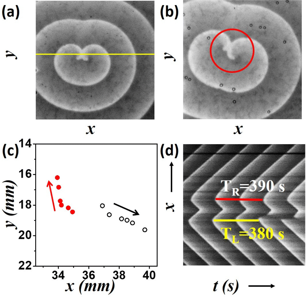 | ||
| Fig. 2 Drift of the spiral tips for an experiment, with 6 beads, at a distance of d = 1.0 cm. (a) Initial snapshot of the experiment just after the addition of the resin beads, (b) snapshot 94 min after the addition of beads. Area of the snapshots are 2.15 cm × 2.15 cm. (c) Position of spiral tips (red full circle, left and black open circle, right) at intervals of 24 min. (d) Timespace plot of the experiment showing time periods of the two tips around 13–18 rotations (78–110 min). | ||
To get a quantitative measure of the drift of the spirals we calculated the distances traveled by the tips for 120 minutes after addition of the resin beads. We calculate the final displacement of the tip from its initial position as the path length, L and the actual distance covered by the tip at every instant along its hypocycloid trajectory, as the traversed distance s. We report here the L and s values for the tip close to the column of resin beads, the left tip in our case. As the number of beads, n, is increased, the drift of the tip increases (Fig. 3(a) and (c)), suggesting a linear dependence of the drift on n. Results for nine experiments with varying d-values show that the trend is same for any separation distance. Hence, more the number of beads, more is the gradient strength. Fig. 3(b) and (d) depict the change in path length, L, and traversed length, s, as functions of d. As the initial separation of the resin beads from the center of the tips increases, the drift of the tip decreases. This means that the net effect of the applied gradient due to a fixed number of beads (n) on the spiral tip decreases, as we move it away from the resin column. When n = 4, the decreasing trend of s is no longer linear (Fig. 3(d)), may be because the gradient strength is a bit weak, and increasing distance renders it even weaker. This is also reflected in the path length (L) for higher d-values.
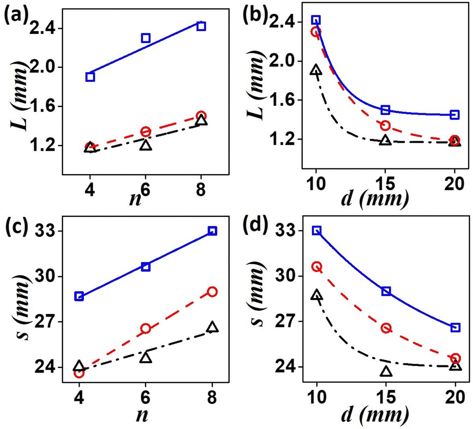 | ||
| Fig. 3 Experimental results. (a) and (b) Path length, L and (c) and (d) traversed length, s of the left tip during 120 min of the reaction. (a) and (c) Variation of L and s with number of beads, n. Blue squares (solid line) are for d = 1.0 cm, red circles (dashed line) are for d = 1.5 cm and black triangles (dashed dotted line) represent values for d = 2.0 cm. (b) and (d) Trend of changing lengths with increasing distance d. Black triangles (dashed dotted line), red circles (dashed line) and blue squares (solid line)are for n = 4, 6, and 8, respectively. | ||
Fig. 4 shows a comparison between the behavior of the left and right tips of the spiral in the path of the gradient. The path length, L, and the traversed length, s, of both the tips is portrayed in Fig. 4(a) and (c), as functions of increasing gradient strength (n) for d = 1.5 cm. It can be observed that the right tip travels more than the left one, s, and L increasing with gradient strength. Fig. 4(b) and (d) depict the effect of separation distance, d for n = 6. A nonlinear decrease of the distances s and L occurred for an increase in the separation, d, with the left tip traversing lower distances than its right counterpart.
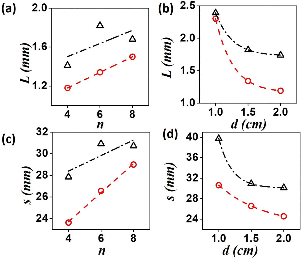 | ||
| Fig. 4 Comparison of drift of the right and left tips of the spiral in experiments. (a) and (b) Path length, L (for d = 1.5 cm) and (c) and (d) traversed length, s (for n = 6) as functions of n and d, respectively. Red circles depict values for the left tip and black triangles for the right tip. | ||
4. Model
The BZ-system is traditionally studied by the Oregonator model which is derived from the FKN mechanism12 of the reaction. The Oregonator model is a three-variable system, that is often simplified to a two-variable activator inhibitor model, where bromous acid (HBrO2) is the activator, u, and the oxidized form of the catalyst, Fe3+, is the inhibitor, v.13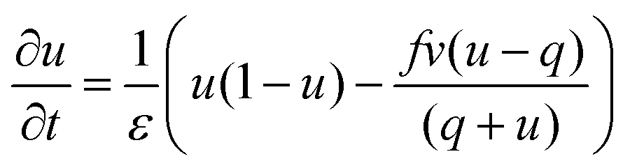 | (1) |
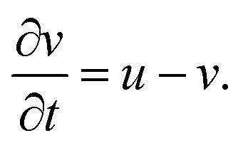 | (2) |
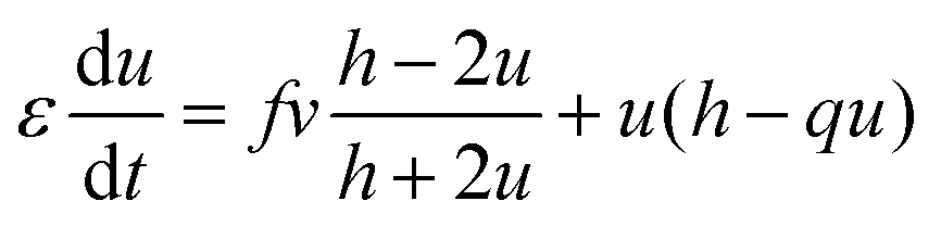
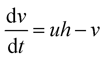
However, the hydrogen ion concentration does not appear explicitly in either the two- or three-variable models of the Oregonator, as it gets embedded in the kinetic parameters f, q and ε. In order to model our reaction system with a source of hydrogen ions in a particular area of the reaction chamber, we had to modify the Oregonator model. A recent work of our group reports the details of our modification of the Oregonator model to include the explicit concentration of the hydrogen ions.30 The modified Oregonator has been derived as a three variable model.
 | (3) |
 | (4) |
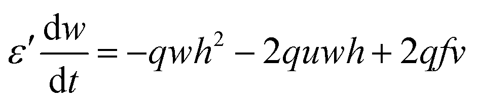 | (5) |
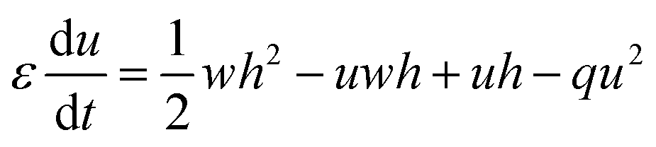
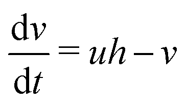
As, ε′ ≪ ε, steady state approximation can be employed on w (as has been done in the original paper of Field, Körös, and Noyes13), giving us-
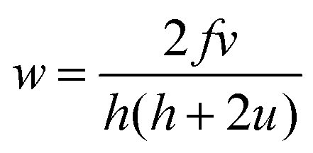
Substituting this value of w in the above equations,3–5 we have a simpler two variable model30 with the following equations:
 | (6) |
 | (7) |
In the presence of diffusion, the modified Oregonator model takes the following form.
 | (8) |
 | (9) |
5. Numerical methods
We integrate the equations8,9 by discretizing the space over 300 × 300 grid points (105 s.u. × 105 s.u.), with the grid spacing kept at 0.35 space units. Euler integration method with time steps of 0.01 time units was employed. The system parameters f = 1.0, q = 0.01, ε = 0.09 are kept constant throughout the simulations. Du and Dv are taken as 0.7 and 0.3, respectively. The initial value of h is taken as h0 = 0.5. This set of parameter values can sustain spiral waves which undergo rigid rotation. We have maintained no flux boundary conditions for our simulations.A target wave is initiated by choosing the wave front and back as isoconcentration areas (u = 0.09, v = 0.0) and (u = 0.0, v = 0.0002), respectively. We allow the wave to expand and at t = 3.0 time units, we cleave it at the middle, like we did in our experiments, by setting zero concentration values as (u = 0.0, v = 0.0). This leads to the formation of a pair of spirals. The spiral tips are identified as the intersection of the iso-concentration lines of umax/2 and vmax/2 values.
To create a gradient of hydrogen ions similar to our experiments, we varied h systematically as per the following equation:
| h(x, t) = h0 + a(105 − x)2 + bt | (10) |
The direction of the gradient and the change in hydrogen ion concentration along the x-direction with time can be understood from Fig. S7 of the ESI.† It shows how the gradient is established if the variation of H+-ions is linear in fashion as compared to a nonlinear variation. An observation of Fig. S7(b) and (c) (ESI†) shows that the maximum limit of hydrogen ion concentration can be achieved faster in case of a linear gradient compared to that of a nonlinear one. We chose the later as it replicates our experimental observations better.
6. Numerical results
We carried out simulations for three different gradient strengths, Δh = 0.04, 0.06 and 0.08. A visual inspection of the numerical experiments revealed a drift of the spiral tips when a gradient in the concentration of H+-ions was introduced into the system, which was absent earlier. The snapshots from two cases, one with zero gradient (Fig. 5(a) and (b)) and another with Δh = 0.04 (Fig. 5(c) and (d)) at two different times are shown in Fig. 5. The later image is after over 200 rotations. It clearly shows that, in the presence of the gradient, there is an appreciable drift of both the tips.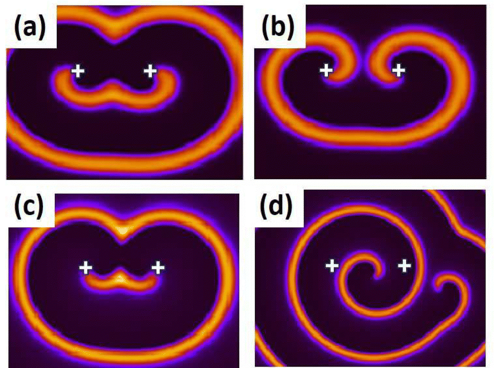 | ||
| Fig. 5 Results of numerical simulations. Snapshots showing the difference between two cases (a) and (b) zero gradient, (c) and (d) Δh = 0.04. (a) and (c) are early snapshots at 150 t.u. and (b) and (d) are snapshots at 1000 t.u. ‘+’ sign marks the initial positions of the spiral tips. | ||
By our definition of the concentration gradient [eqn (10)], the value of h(x, t) experienced by the two tips are different, the left tip enduring a larger value of h(x, t) at any given time than its right counterpart. This accounts for the faster rotation of the left spiral as compared to the right one, its expanding wave arm causing a greater drift of the right tip (Fig. 5d). This is clearly reflected in the tip trajectories of the two spiral tips. Trajectories from four numerical experiments, with varying Δh-values are depicted in Fig. 6. With time the two tips are moving away from each other, the left tip moving in an upwardly fashion, while the right tip moves downward. The distance covered in the case of higher gradient is observably larger.
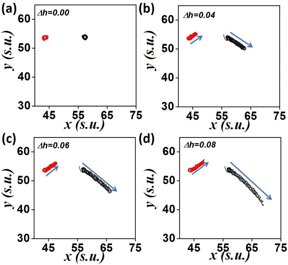 | ||
| Fig. 6 Movement of spiral tips under a concentration gradient. Trajectories of the spiral pair for 1000 t.u. at different gradient strengths (a) Δh = 0.0 (b) Δh = 0.04 (c) Δh = 0.06, and (d) Δh = 0.08. d-Value is kept constant at 50.75 s.u. | ||
The distance traversed by both the spiral tips are plotted in Fig. 7(a) and (c) as functions of Δh. The path length (final displacement of the tip), L, and traversed length (actual distance covered by a tip), s, are seen to increase with gradient strength. Next we varied the initial position of the spiral, with respect to the left boundary, where the value of h is the highest (Fig. 7(b) and (d)). With increasing d-values, the net drift decreases. The path length of the left tip (red circles in the figures) is smaller than the right one (black triangles in figure), in a given time. This was also evident from the plots of the trajectories (Fig. 6). This could be because the left tip rotates faster causing the greater drift of the right spiral.
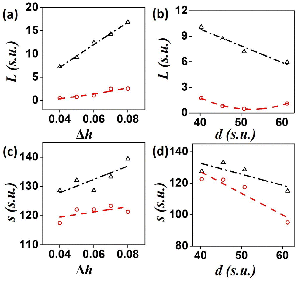 | ||
| Fig. 7 Influence of gradient strength on drift of spiral tips. (a) and (c) show the trend of path length, L and traversed length, s on varying values of Δh. (b) and (d) are plots for L and s with changing spiral position, d. Distances covered at 900 time units by the left tip are depicted as red circles (dashed) and that by the right tip as black triangles (dash-dot). In (a) and (c) d = 50.75 s.u. and in (b) and (d) Δh = 0.04. | ||
All these quantitative analysis and numerical results can also be read in more simpler way, with an observation of the snapshots. Fig. S4 in the ESI,† show the drift of spiral tips with increasing gradient strength, while Fig. S5 (ESI†) describes the effectiveness of a particular gradient strength. Snapshots reveal that the higher gradient strength causes more drift and the effectiveness decreases with separation distance.
7. Discussions and conclusions
7.1. Discussions
By introducing a source of protons into an otherwise homogeneous layer of BZ solution (gel), we have successfully employed a chemical gradient in the system. When spiral waves are subjected to this gradient of protons released from the ion exchange resin beads, their motion is affected by the resulting inhomogeneity. We have observed that the tip lying close to the column of beads starts rotating faster than its counterpart, albeit with only a slight increase in frequency. Both spiral tips start reorienting themselves, and the left tip moves towards the top of the medium, while the right one moves downward. Such a kind of reorientation of spiral tips, and subsequent breaking of the symmetry of the two counterrotating tips, leading to deformation of spiral shape, was also seen in earlier studies with stronger gradients like electric field.21,31,32 Here it was observed that the two spiral tips separated from each other as they moved towards the anode. In yet another study, it was observed that the distance between the two spiral tips would decrease with time.20 In our case, we observed that the distance between the two counter-rotating spiral tips kept on increasing over time.In our numerical simulations, we carried out studies considering the gradient strength as a function of distance and time. The time variation of the h-gradient that has been considered linear by us, can be supported by experimental measurements. We observed a nonlinear time-release of protons by the resin beads in a stirred homogeneous unreactive system, however this turns linear in a stirred homogenous BZ medium, which has the same recipe as our experimental system (Fig. S6, ESI†). Initially, we considered h as a linear function of the distance x (starting from the column of resin beads), as h(x, t) = h0 + a(105 − x) + bt. However, the trends obtained from our computational studies did not exactly match that of our experiments. With this linear-gradient, we have observed that the movement of the left tip shows a decreasing trend with increasing gradient strength. This is opposite to that observed in our experiments. We also approached the problem by adding a third reaction-diffusion equation for [H+] or variable-h, to our system of eqn (8) and (9). Since the initial H+-ion concentration is in excess, the numerical simulation for this third variable blows up, in comparison to the other two, and no oscillations are obtained even for the non-diffusing system. Considering only diffusion for h, with a constant initial hydrogen ion concentration throughout the medium, and a patch of high concentration at the left boundary, which would be akin to the experimental situation, we still arrive at similar results as the linear gradient. The reason for this will be that the H+ ions are also undergoing reaction as they diffuse through the medium. Fig. S7 (ESI†) displays a comparison of hydrogen ion mobility for the three cases: diffusion, linear gradient and nonlinear gradient, and the corresponding results for our simulation. Considering the nonlinear variation of the gradient strength (as in eqn (10)), the results now matched the experimental observation more closely. This points to a non-linear variation of the gradient in space. This nonlinearity is markedly different from any external gradient that one may employ, like electromagnetic fields or thermal gradients. The movement of the hydrogen ions in the 2D space as ion exchange takes place, leading to a gradient in the concentration of protons, will be an interesting study by itself, and may be carried out in the future. Furthermore, our numerical simulations allow us to study the effects of a stronger concentration gradient across larger distances.
7.2. Conclusions
In conclusion, we can summarize that a concentration gradient can influence the dynamics of spiral waves. A proton-exchange resin bead that does not bind to the metal catalyst is an able candidate for the introduction of a concentration gradient within the homogeneous BZ media. In our experiments we observed that drift of the spiral tips were higher with more number of beads and decreased as we moved the spiral away from the column of beads (increased d). In our numerical simulations with the modified Oregonator model that we developed to include the explicit effect of the H+-ion concentration at every point in space, we observed similar changes in the spiral dynamics with a nonlinear form of gradient. As the spiral was shifted away from the left boundary (high concentration), the drift decreased. One may wonder if there is a critical distance beyond which the effect of the concentration gradient is negligible. Future work can be carried out with this aim. The conclusions drawn from this work improves our understanding of the effect of ionic gradient on these excitation waves, and may help us in their control in biological systems, such as cardiac tissues. Just like an electric field gradient affects the excitability of the medium by modifying the diffusion or mobility of ions in a chemical system33 and the potential in a cardiac muscle,34 similarly a concentration gradient of Na+ or K+ ions in the cardiac tissue can change the excitability of the tissue at different regions, as it does in the BZ-system, thus leading to a mechanism for the control of excitation waves.Data availability
All relevant data are within the manuscript and its ESI.†Conflicts of interest
There are no conflicts of interest with individuals or organizations to declare.Acknowledgements
This work was financially supported by the Department of Science and Technology, Science and Engineering Research Board, Government of India (Grant No. CRG/2019/001303).References
- W. Jahnke, W. E. Skaggs and A. T. Winfree, J. Phys. Chem., 1989, 93, 740–749 CrossRef CAS.
- J. Jalife, M. Delmar, J. Anumonwo, O. Berenfeld and J. Kalifa, Basic Cardiac Electrophysiology for the Clinician, Wiley-Blackwell, Oxford, UK, 2nd edn, 2009 Search PubMed.
- F. X. Witkowski, L. J. Leon, P. A. Penkoske, W. R. Giles, M. L. Spano, W. L. Ditto and A. T. Winfree, Nature, 1998, 392, 78–82 CrossRef CAS PubMed.
- E. M. Cherry and F. H. Fenton, New J. Phys., 2008, 10, 125016 CrossRef.
- J. Jalife, R. A. Gray, G. E. Morley and J. M. Davidenko, Chaos, 1998, 8, 79 CrossRef PubMed.
- E. Pálsson, K. J. Lee, R. E. Goldstein, J. Franke, R. H. Kessin and E. C. Cox, Proc. Natl. Acad. Sci. U. S. A., 1997, 94, 13719 CrossRef PubMed.
- X. Huang, W. Xu, J. Liang, K. Takagaki, X. Gao and J. Y. Wu, Neuron, 2010, 68, 978 CrossRef CAS PubMed.
- N. A. Gorelova and J. Bures, J. Neurobiol., 1983, 14, 353–363 CrossRef CAS PubMed.
- A. T. Winfree, Science, 1972, 175, 634 CrossRef CAS PubMed.
- S. Nettesheim, A. von Oertzen, H. H. Rotermund and G. Ertl, J. Chem. Phys., 1993, 98, 9977 CrossRef CAS.
- S. Dutta, N. P. Das and D. Mahanta, Dynamics and Control of Spiral and Scroll Waves, Complexity and Synergetics, Springer, Cham, 2018, pp. 155–165 Search PubMed.
- R. J. Field, E. Körös and R. M. Noyes, J. Am. Chem. Soc., 1972, 94, 8649–8664 CrossRef CAS.
- R. J. Field and R. M. Noyes, J. Chem. Phys., 1974, 60, 1877 CrossRef CAS.
- S. K. Scott, Oscillations, waves, and chaos in chemical kinetics, Oxford University Press, Oxford, 2nd edn, 1994 Search PubMed.
- A. T. Winfree, Faraday Symposia of the Chemical Society, Royal Society of Chemistry, 1974, 9, 38–46 Search PubMed.
- S. Dutta, S. S. Riaz and D. S. Ray, Phys. Rev. E, 2005, 71, 036216 CrossRef PubMed.
- H. Sevčíková, M. Marek and S. C. Müller, Science, 1992, 257, 951–954 CrossRef PubMed.
- S. Dutta and D. S. Ray, Phys. Rev. E, 2007, 75, 066206 CrossRef PubMed.
- M. Kuze, M. Horisaka, N. J. Suematsu, T. Amemiya, O. Steinbock and S. Nakata, J. Phys. Chem. A, 2019, 123, 4853–4857 CrossRef CAS PubMed.
- K. I. Agladze and P. De Kepper, J. Phys. Chem., 1992, 96, 5239–5242 CrossRef CAS.
- O. Steinbock, J. Schütze and S. C. Müller, Phys. Rev. Lett., 1992, 68, 248–251 CrossRef CAS PubMed.
- P. Sadeghi and H. H. Rotermund, Chaos, 2011, 21, 013125 CrossRef PubMed.
- S. Luther, F. Fenton and B. Kornreich, et al. , Nature, 2011, 475, 235–239 CrossRef CAS PubMed.
- M. Vinson, S. Mironov, S. Mulvey and A. Pertsov, Nature, 1997, 386, 477–480 CrossRef CAS PubMed.
- N. P. Das and S. Dutta, Phys. Rev. E, 2017, 96, 022206 CrossRef PubMed.
- D. Kupitz, S. Alonso, M. Bär and Marcus J. B. Hauser, Phys. Rev. E, 2011, 84, 056210 CrossRef PubMed.
- S. Dutta and O. Steinbock, Phys. Rev. E, 2011, 83, 056213 CrossRef PubMed.
- D. Mahanta, N. P. Das and S. Dutta, Phys. Rev. E, 2018, 97, 022206 CrossRef CAS PubMed.
- T. Plesser, S. C. Mueller and B. Hess, J. Phys. Chem., 1990, 94, 7501–7507 CrossRef CAS.
- P. Khan and S. Dutta, arXiv, 2024, preprint, arXiv:2403.15731 DOI:10.48550/arXiv.2403.15731.
- J. Chen, H. Zhang and Y. Li, J. Chem. Phys., 2006, 124, 014505 CrossRef PubMed.
- M. Seipel, M. Zierhut and A. F. Münster, ChemPhysChem, 2001, 2, 613–616 CrossRef CAS PubMed.
- V. Pérez-Muñuzuri, R. Aliev, B. Vasiev and V. I. Krinsky, Physica D, 1992, 56, 229–234 CrossRef.
- A. Pumir, F. Plaza and V. I. Krinsky, Proc. R. Soc. London, Ser. B, 1994, 257, 129–134 CAS.
Footnote |
| † Electronic supplementary information (ESI) available. See DOI: https://doi.org/10.1039/d4cp03734k |
| This journal is © the Owner Societies 2025 |