 Open Access Article
Recent advances in potassium metal batteries: electrodes, interfaces and electrolytes
Jianlu
Sun
a,
Yichen
Du
a,
Yijiang
Liu
bc,
Dongbo
Yan
a,
Xiaodong
Li
a,
Dong Ha
Kim
 *d,
Zhiqun
Lin
 *bd and
Xiaosi
Zhou
 *a
*a
aSchool of Chemistry and Materials Science, Nanjing Normal University, Nanjing 210023, China. E-mail: zhouxiaosi@njnu.edu.cn
bDepartment of Chemical and Biomolecular Engineering, National University of Singapore, Singapore 117585, Singapore. E-mail: z.lin@nus.edu.sg
cCollege of Chemistry and Key Laboratory of Environmentally Friendly Chemistry and Application of Ministry of Education, Xiangtan University, Xiangtan 411105, Hunan Province, China
dDepartment of Chemistry and Nano Science, Ewha Womans University, 52 Ewhayeodae-gil, Seodaemun-gu, Seoul 03760, Republic of Korea. E-mail: dhkim@ewha.ac.kr
First published on 7th February 2025
Abstract
The exceptional theoretical capacity of potassium metal anodes (687 mA h g−1), along with their low electrochemical potential, makes potassium metal batteries (PMBs) highly attractive for achieving high energy density. This review first provides an overview of potassium metal anodes, including their origin, current development status, and distinctive advantages compared to other metal anodes. Then, it discusses the composition and characteristics of emerging breakthrough PMBs, such as K–S, K–O2, K–CO2 batteries, and anode-free metal batteries. Subsequently, we delve into the pivotal challenges and theoretical research pertaining to PMBs, such as potassium metal nucleation/stripping, dendritic growth in PMBs, and unstable interfaces. Furthermore, we comprehensively examine the latest strategies in electrode design (including alloy, host, and current collector design), interface engineering (such as artificial solid electrolyte interphase layers, barrier layer design, and separator modification), and electrolyte optimization concerning nucleation, cycling stability, coulombic efficiency, and the development of PMBs. Finally, we introduce key characterization techniques, including in situ liquid phase secondary ion mass spectrometry, titration gas chromatography, neutron-based characterization, and computational simulation. This review will propel advancements in electrodes, separators, and electrolytes for innovative PMBs and other similar alkali metal batteries.
1. Introduction
The deep integration of clean and renewable energy with the power grid system effectively addresses the pressing demand for high energy efficiency and low-emission alternatives, while substantially alleviating the severe ecological degradation caused by the consumption of traditional fossil fuels such as coal, oil, and natural gas.1,2 During this transformative process, clean energy technologies like hydropower, wind power, and solar cells, though widely applied and with broad prospects, are inevitably constrained by geographical location, climate conditions, and environmental factors, leading to intermittent and unstable energy supplies.3–5 Therefore, the exploration and development of efficient and reliable energy storage technologies have become pivotal strategy to ensure a stable supply of renewable energy and facilitate flexible scheduling within the energy system.6–8 In this context, secondary batteries, as an advanced energy storage technology, are increasingly prominent in driving the global energy structure transformation due to their high energy density, long cycle life, fast charging and discharging capabilities, and good environmental adaptability.9–11 These batteries not only effectively smooth the intermittent output of renewable energy and improve the stability and reliability of the power grid but also release stored energy during peak demand periods, thereby optimizing energy allocation and enhancing the flexibility of the energy system.12,13With continuous advancements in materials science, electrochemistry, and intelligent control technology, the performance of secondary batteries has been steadily improving, while costs are gradually decreasing.14–16 This progress holds immeasurable value in promoting a harmonious balance between environmental and economic development.17,18 Lithium-ion batteries, in particular, offer an energy density of 200–300 W h kg−1 and are widely used in portable electronic devices, electric vehicles, and energy storage systems due to their advantages of high energy density, long lifespan, and low self-discharge.19,20 However, the limited and uneven distribution of lithium resources (approximately 0.0017 wt%), along with high costs, have constrained their further development.21–23 Therefore, leveraging the abundant reserves of potassium in the Earth's crust (approximately 2.09 wt%) and its relatively lower cost, the development of potassium-ion batteries presents a new solution for large-scale global energy storage and conversion.24,25 Moreover, in common ester electrolytes, the solvation radius of K+ is smaller than that of Li+ or Na+, enabling faster migration of K+ between electrodes. This gives potassium-ion batteries significant advantages in applications requiring rapid charging and high-power output.26,27
Potassium-ion batteries originated in 2004, and since then, a wide range of electrode materials, separators, and electrolytes related to potassium-ion batteries have been extensively explored (Fig. 1).28–30 The potassium metal anode, due to its low chemical potential and a high theoretical capacity of up to 687 mA h g−1, far exceeding most other anodes, has become research focus.31 This feature not only endows the potential for higher energy density in potassium metal batteries (PMBs) but also holds significant implications for advancing the development of new high-energy density metal batteries, particularly when coupled with high-capacity cathode materials such as sulfur (S) and oxygen (O2).32–34 Since its first report in 2014, K–S batteries have attracted researchers to continuously delve into the electrochemical reaction pathways and kinetic mechanisms associated with S cathodes, even though the system is still in its early stages of development.35–37 Depending on the different potassium polysulfide intermediates, the reaction pathway of the S cathode can be categorized into two distinct routes: the solution-mediated solid–liquid–solid conversion pathway and the direct solid–solid reaction.38,39 However, the development of K–S batteries faces multiple challenges, including the shuttle effect of polysulfides, the complexity of reaction mechanisms under different voltage windows, issues with electrolyte decomposition, and significant volume changes in electrodes.40,41 To overcome these obstacles, researchers focus on developing efficient sulfur-loaded composite materials, improving separator designs, and exploring more stable electrolyte compositions.42,43
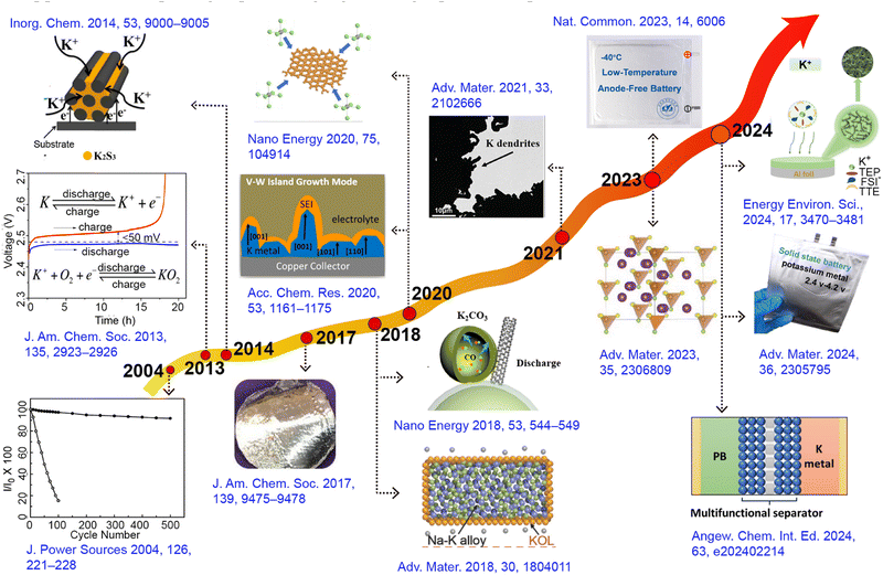 | ||
| Fig. 1 Timeline showing major developments in the field of PMBs: new electrode materials, separators, electrolytes, and theoretical concepts. | ||
In another domain, metal–air batteries as hybrid structures combine the characteristics of fuel cells.44 Lithium–oxygen (Li–O2) batteries demonstrate an impressive theoretical specific energy of 3500 W h kg−1, indicating enormous application prospects.45,46 Nevertheless, the practical capacity of Li–O2 batteries is significantly lower than theoretical predictions due to the inability of Li2O2 to achieve reversible cycling in its pure substance form.47 Conversely, the single-electron reversible reaction between oxygen and KO2 in the K–O2 system, first proposed by Wu's group in 2013, provides a new avenue for the advancement of metal–air batteries.48,49 This system uses potassium metal as the anode and a porous carbon cathode connected to oxygen as the counter electrode, achieving a single-electron redox process without the need for electrocatalysts.50,51 In this process, the chemical stability between the electrolyte and superoxide anion becomes a key factor in ensuring the long cycle life of the battery. Additionally, in 2018, Zhang et al.52 successfully overcame the operational challenges of potassium–carbon dioxide (K–CO2) batteries, thereby broadening the horizons of potassium metal battery research (Fig. 2a). However, subsequent studies have found significant charge/discharge polarization in the K–CO2 battery system, which considerably reduces energy efficiency and cycling stability.53 To address this issue, researchers have conducted preliminary explorations to improve the kinetics of carbon dioxide reduction, aiming to optimize battery performance.54,55
In these emerging battery systems, the stability of K metal anodes during electroplating or stripping processes cannot be overlooked in its influence on the reversible capacity of the battery. The nucleation and deposition behavior of K metal anodes on current collectors is similar to that of Li and Na, and it also faces the ubiquitous problem of dendrite growth common to all alkali metals.56–58 From the perspective of physical properties, K has a lower hardness than Li and Na, suggesting that the theoretical difficulty of K dendrites penetrating the solid electrolyte interphase (SEI) and separator is relatively significant.21,59 However, experimental evidence indicates that the higher reactivity of K and its more substantial volume change during charge/discharge cycles compared to Li and Na exacerbate the fragility of the SEI, leading to more pronounced dendrite growth.60,61 This not only reduces the coulombic efficiency (CE) of the battery but also significantly shortens its cycle life. A comprehensive introduction and analysis of the challenges confronting PMBs were presented in Section 2.
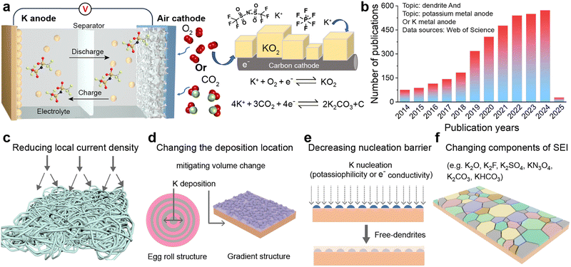
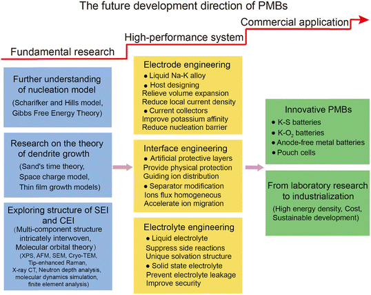
Over the past five years, research on K metal anodes has seen a marked acceleration in depth and breadth. In Section 3, we reviewed various strategies and methods proposed to address the stability concerns of K metal anodes. To obtain high-performance K metal anodes, researchers have mainly adopted three strategies: electrode design, interface modification, and electrolyte regulation. Electrode design encompasses the preparation of alloy negative electrodes and the construction of K metal composites. Interface modification can be divided into in situ/ex situ protective layers or guiding layers, which can be achieved by directly modifying the electrode surface or indirectly modifying the separator surface. Electrolyte modulation involves altering the composition of salts or solvents in liquid electrolytes and exploring solid electrolytes. The research on these strategies and methods primarily revolves around the following objectives: firstly, in the study of K metal hosts, constructing three-dimensional (3D) structures to largely reduce local current density and provide sufficient accommodation for electrode volume expansion (Fig. 2c and d). Secondly, electrode design and potassium-friendly interface modifications focus on reducing nucleation barriers and improving the internal electric field distribution to direct uniform potassium ion flux (Fig. 2e). Finally, the purpose of the interface protective layer and electrolyte regulation is to enhance SEI stability, thereby mitigating side reactions and dendrite growth (Fig. 2f). Furthermore, electrodes, interfaces, and electrolytes are crucial for the solvation–desolvation, diffusion, and nucleation processes of potassium ions. Notably, the research on current collectors and electrolytes is of great significance for developing anode-free batteries with higher energy density and safety.62 In Section 4, we summarized the structural optimizations and common characterization techniques of PMBs, and provided insights for future development directions. Through continuous technological innovation and material optimization, PMBs will play a prominent role in the future energy storage field.
2. Key challenges for PMBs
2.1. Uncontrolled potassium metal nucleation
When exploring the charging mechanism of K metal anodes, we noticed a significant distinction from traditional graphite materials. Potassium ions are not embedded in the host material but instead directly acquire electrons on the surface of K metal, thereby initiating the metal nucleation process. The nucleation behavior of K metal affects the subsequent deposition morphology, dendrite development, and SEI formation. When uncontrolled potassium metal nucleation is non-planar, it can lead to local current density enhancement and promote dendrite growth.59 Exploring potassium metal nucleation models can provide a fundamental theoretical foundation for optimizing potassium nucleation in electrodes, interfaces, and electrolytes, ultimately aiming to enhance cycling stability of PMBs. The following section will introduce the classical nucleation model and assess its applicability and limitations to PMB systems.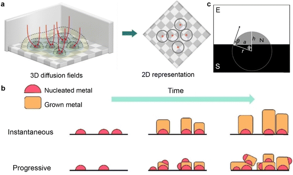 | ||
| Fig. 3 (a) Left: ions diffuse through spherical diffusion fields (colored regions) towards the hemispherical nuclei (pink hemispheres) on the electrode surface (checkered area). Some example pathways are indicated with arrows. Right: A 2D representation of the 3D diffusion fields. The rings represent the diffusion zones for each nucleus. (b) Schematic diagram of instantaneous versus progressive growth. Reproduced with permission from ref. 66. Copyright 2023, Wiley-VCH. (c) Schematic illustration of cape-shaped nucleation on the substrate immersed in the electrolyte. Reproduced with permission from ref. 67. Copyright 2013, IOP science. | ||
The SH model proposes two extreme nucleation modes: instantaneous nucleation mode and progressive nucleation mode. In the instantaneous nucleation mode, once the initial atomic cluster nuclei are formed, subsequent metal deposition mainly revolves around these predetermined nuclei (Fig. 3b). The progressive nucleation mode indicates that, in addition to the initial crystal nuclei, new crystal nuclei continue to form over time alongside existing crystal nuclei, creating a competitive scenario between new and old crystal nuclei in the subsequent deposition process. Although instantaneous nucleation tends to produce crystals with good structures, uneven initial distribution of crystal nuclei may lead to preferential growth in specific regions, resulting in uneven surface morphology of the deposited material. Various external factors, including overpotential, temperature, electrolyte composition, and pH value, profoundly impact the nucleation mode and surface morphology of metals.68,69 Taking the study by Raeissi et al.70 as an example, they conducted a detailed analysis of the deposition behavior of zinc on steel substrates. By comparing experimental data with curves derived from the SH model equation, they revealed that as the pH value increased from 2 to 4, the deposition of zinc shifted from being dominated by instantaneous nucleation to progressive nucleation.
However, the SH model has certain limitations in describing complex systems, particularly as it fails to consider the discrepancies in nucleation sites on different substrates and the impact of SEI formation on ion diffusion. To enhance the correlation of the model in complex systems such as batteries, Thirumalraj et al.71 introduced a new factor JSEI, which encapsulates the effects of electrolyte decomposition. By incorporating this factor, they modified the SH model and proposed the Li-SEI model. This model provides a powerful tool for quantitative study of lithium nucleation and growth in different electrolytes. The unique nucleation mechanism of K metal anodes during charging requires us to re-examine and possibly adjust existing nucleation theoretical models. Future research should focus on how to precisely control the nucleation process to optimize the performance and stability of PMBs.
 | (1) |
 | (2) |
 | (3) |
Symbols are summarized in Table 1.
| Symbol | Description |
|---|---|
| ΔGT | Total Gibbs free energy of transformation |
| ΔGf | Volume free energy of transformation |
| γ NE | Interfacial free energy between the nucleus and electrolyte |
| γ SN | Interfacial free energy between the substrate and the nucleus |
| γ SE | Interfacial free energy between the substrate and electrolyte |
| Ω | Molar volume of deposit |
| η | Overpotential |
| S v | Volumetric shape factor of deposit |
| S A | Area shape factor of deposit |
| θ | Contact angle |
| F | Faraday's constant |
| r | Radius of curvature of deposit |
| V m | Molar volume of alkali metal |
When evaluating the interfacial energy between metals and substrates, it is necessary to thoroughly consider the lattice matching between the two materials.76,77 Early studies systematically explored the lattice matching of lithium on different substrate materials, including copper, tin, gold, zinc, and carbon.78–80 These studies provide useful references for optimizing the wettability between metals and substrates. By increasing the wettability between the metal and the substrate, the thermodynamic conditions for nucleation can be significantly improved, thereby promoting the efficiency of metal deposition.81 It is noteworthy that, while Gibbs free energy theory does not consider the time factor in describing the nucleation process of metal deposition and thus cannot directly determine the main mode of metal nucleation (such as instantaneous nucleation or continuous growth), this model retains significant theoretical value. It comprehensively considers the influence of metal core size, electrode material, electrolyte properties, and interfacial energy on the heterogeneous nucleation process. This model can provide crucial theoretical guidance and practical foundations for the design of electrode materials and optimization of electrolytes in PMBs.
2.2. Severe dendrite growth
The formation of dendrites on metal anodes can have detrimental effects on the SEI covering the electrode surface.82,83 Specifically, the growth of dendrites can compromise the integrity of the SEI, consume significant amounts of electrolytes, and lead to an uneven distribution of the SEI, ultimately impeding ion transport processes.84 Moreover, dendrites are susceptible to fracture, transforming into inactive metallic fragments that are incapable of transferring electrons.85 This transformation exacerbates polarization and reduces battery efficiency. The growth of metal dendrites, particularly severe in potassium metal due to its high reactivity, leading to battery short-circuits, poses a major obstacle in the field of alkali metal anode research. Its intricate mechanisms have attracted the attention of many researchers.In the study of metal dendrites, the most widely accepted theories are the Sand's time theory proposed by Henry Sand in 1901 and the space charge model constructed by Chazalviel in 1990.86,87 Sand discovered that while investigating copper electrodeposition in aqueous solutions, when the electrode current exceeds the diffusion-limited current, the salt concentration on the electrode surface will drop to near-zero levels at a characteristic time (tSand, eqn (4)). Under conditions of ion scarcity, metal ions will preferentially deposit on the protrusions on the metal surface, triggering a transition from uniform electroplating to tip growth mode. Similarly, Kim and Jorne observed that zinc dendrites tend to grow at the edge of the rotating disk with high local current density while studying the kinetics of zinc electrodes in acidic zinc chloride solutions.88 Chazalviel proposed an explanatory mechanism from the perspective of space charge.87 He demonstrated that the growth of metal tip branches in dilute salt solutions is driven by the space charge locally generated when ions are depleted. Nevertheless, this model is no longer applicable when convection exists in the system, such as caused by factors like stirring or gravity.
 | (4) |
In 2003, Monroe and Newman discovered that in lithium/polymer batteries, even when the current is much lower than the diffusion-limited current, the growth time of lithium dendrites aligns with Sand's time.89 In 2016, Bai et al.84 observed whisker growth (i.e., mossy dendrites) at the roots of lithium during the initial stages of deposition, under conditions below the limiting current, which then transitioned into dendritic structures, forming a typical branching architecture. They further proposed a combination of the Sand's capacity theory and considerations of the stress effect beneath the SEI layer to reveal the growth of lithium dendrites based on the Sand's time theory. In 2018, Wang et al.90 proposed a stress-driven model to explain the growth of lithium root whiskers, and experimentally validated that depositing lithium on soft substrates can effectively release stress and suppress dendrite growth.91 Jäckle and Groß attempted to elucidate the phenomenon of dendrite formation on lithium surfaces using a surface diffusion model, and compared it with the relatively smooth surfaces of magnesium.92 They pointed out that magnesium has a low surface diffusion energy barrier, with strong adsorption between atoms, which tends to self-diffuse on rough surfaces to form dense surfaces.93,94 However, the model overlooked the difficulty of observing atomic-level deposition and the interaction forces between SEI and atoms.
Although both Sand's theory and Chazalviel's model emphasize the impact of diffusion-induced interface ion depletion on local electric field changes on metal deposition, they have encountered limitations in explaining the growth of potassium dendrites. The migration rate of potassium ions in common electrolytes is relatively fast, suggesting that ion depletion due to concentration polarization should be less severe than that of lithium. In fact, K dendrites remain severe even at currents below the limiting current or in high concentration electrolytes.95 To address this issue, Liu et al.59 proposed a new insight in 2020: the less stable SEI on the surface of K may be one of the reasons for the severe growth of K dendrites. They explained the K electroplating process by combining the wettability between K and copper current collectors with classical thin film growth models. Thin film growth can be divided into three modes: planar growth (Frank van der Merwe; F-M growth), island growth (Volmer–Weber; V–W growth), and transition from planar to local dewetting (Stranski–Krastanov growth) (Fig. 4). During the K electroplating process, the formation of SEI leads to an increase in overpotential and the occurrence of local dewetting island-like growth. This model emphasizes the importance of controlling electrolyte composition and energy barrier between K and interface to inhibit K dendrite growth.
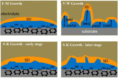 | ||
| Fig. 4 Schematic illustration of the wetting behavior of K metal deposits electrochemically plated on a planar support. Reproduced with permission from ref. 59. Copyright 2020, American Chemical Society. | ||
Some dendrites are affected by the internal stress of the SEI layer, resulting in the formation of small whiskers at the root of the dendrites.96–98 These newly generated whisker surfaces exhibit exceptionally high reactivity, creating new and unstable SEI layers. During the subsequent discharge process, these newly formed SEI layers reduce the ion diffusion resistance, facilitating the dissolution of the dendrite roots and causing the dendrites to detach from the current collector.99 This phenomenon not only decreases the CE of metal batteries but also leads to a rapid decline in battery performance. For anode-free K batteries, low CE is a key factor restricting battery lifespan.100 Potassium ions, upon acquiring electrons, undergo nucleation and electrodeposition directly on the surface of the current collector. In this process, the positive electrode is irreplaceable, and the resultant low CE accelerates battery failure. Inactive and active metals are mostly surrounded by SEI, making it difficult to distinguish them. To further quantify deactivated metals, Fang et al.101 developed a titration gas chromatography method, utilizing the difference in reaction activity between lithium complexes in the SEI and metallic lithium in proton solvents. By monitoring the amount of gas produced from the reaction with proton solvents, the relative proportion of unreacted lithium and lithium complexes in the SEI layer can be indirectly inferred, providing support for further understanding of deactivated metals.
2.3. Unstable interface
The SEI is regarded as a multi-component structure intricately interwoven with inorganic and organic phases, and its concept was initially proposed by Peled et al.102–104 during their meticulous study of the surface properties of lithium metal. This SEI spontaneously forms on the surfaces of alkali metal anodes and continues to grow even at open circuit potential, a process closely related to the electrolyte composition.105,106 To elucidate the formation mechanism of the SEI from a theoretical perspective, Goodenough et al.107 employed molecular orbital theory to provide a detailed description of the electrolyte reduction process. A robust SEI characterized by high ionic conductivity and mechanical resilience is essential for regulating ion flux and mitigating ongoing side reactions.108,109 Compared to other alkali metals, the SEI layer formed on a K metal anode exhibits greater instability, mainly due to the significant volume fluctuations of K during charge/discharge processes, as well as the sparse and uneven distribution of inorganic compounds (e.g., KF) within the SEI on the K surface.110–112 Researchers have emphasized that the composition, thickness, and uniformity of the SEI layer are pivotal factors affecting dendritic formation on metal surfaces.113,114To comprehensively understand the morphology and structure of SEI, researchers have employed various advanced analytical techniques, such as Fourier transform infrared spectroscopy (FTIR), X-ray diffraction (XRD), X-ray photoelectron spectroscopy (XPS), atomic force microscopy (AFM), scanning electron microscopy (SEM), and cryo-transmission electron microscopy (cryo-TEM).115–117 Notably, Nanda et al.118 leveraged tip-enhanced Raman spectroscopy to analyze the dynamic evolution process of SEI on amorphous silicon (Si) substrates, confirming that SEI is composed of embedded multi-layer nanoscale mixtures of carboxylate and fluoride (Fig. 5a and b). In addition, Zhou et al.119 monitored the chemical spectral changes of substances on copper surfaces in real-time using in situ liquid secondary ion mass spectrometry (Fig. 5c–e). Dynamic observation revealed that on the copper surface, SEI exhibits a unique bilayer inorganic–organic structure, distinct from the previously observed random dispersions. Jeschull et al.120 used XPS to compare the characteristics of SEI on graphite electrodes in potassium half-cells and full-cells, discovering significant differences in chemical composition and thickness (Fig. 5f and g). These results highlight substantial discrepancies in SEI characteristics among different battery configurations, indicating the limitations of inferring full-cell mechanisms based solely on half-cell data.
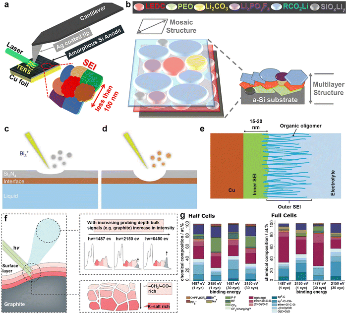 | ||
| Fig. 5 (a) Schematic illustration of the tip-enhanced Raman spectroscopy (TERS) setup for measuring the SEI on the surface of cycled amorphous Si (a-Si) with nanoscale in-plane resolution. (b) Schematic of the SEI structure on the cycled a-Si surface. Reproduced with permission from ref. 118. Copyright 2019, Elsevier. (c) A thin silicon nitride (Si3N4) membrane was used to separate the liquid from a high vacuum. During the initial stage of the SIMS analysis, only Si3N4-related signals were detected. (d) Interfacial signals begin to appear after a Bi3+ primary ion beam drills through the Si3N4 membrane. (e) The SEI can be divided into two parts: an inner SEI and an outer SEI. Reproduced with permission from ref. 119. Copyright 2020, Springer Nature. (f) Graphical summary of the photoelectron spectroscopy depth profiling study. (g) Surface composition analysis derived from in-house (1487 eV) and hard X-ray photoelectron spectroscopy (2150 eV) spectra recorded for graphite electrodes cycled in half and full cells. Reproduced with permission from ref. 120. Copyright 2024, Wiley-VCH. | ||
Equally important is the stability of the cathode electrolyte interphase (CEI) in high-voltage battery systems.121,122 Specifically, common issues with CEI include cracking, dissolution, and unevenness stemming from irreversible phase transitions or volume changes in the cathode.123,124 Current research predominantly suggests that the specific adsorption and solvation structures of the electrolyte or the testing voltage window will affect the formation of CEI, but the specific formation mechanism has not been elaborated in detail.125–127 Contrary to the expected instability of CEI at high voltage, Seong et al.128 found that due to the rapid dissolution of the damaged CEI (as opposed to the accumulation process), LiCoO2 exhibited more stable cycling performance at a cut-off voltage of 4.8 V compared to 4.6 V. Other researchers have pointed out that CEI decomposes during the high-voltage charging stage, and high voltage has almost no effect on its growth.129,130 Rather, its formation process is more modulated by the discharge process and anode side reactions.131 In PMBs, stable CEI and SEI often rely on the incorporation of artificial interface layers or strategic electrolyte component design. A deeper understanding of the formation mechanisms of electrode/electrolyte interface, including both SEI and CEI, provides scientific guidance for the rational design of PMBs.
3. Optimization strategies for advanced PMBs
3.1. Electrode engineering
To address the issues of large volume fluctuations and dendrite growth in K metal anodes during cycling, numerous strategies have been continuously proposed, including designing K composite electrodes and modifying current collectors.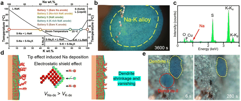 | ||
Fig. 6 (a) Phase diagram of the Na–K anode. Reproduced with permission from ref. 135. Copyright 2023, Elsevier. (b) Optical microscope images of metal deposition behaviors on the Cu electrode and (c) the corresponding energy dispersive X-ray spectroscopy (EDS) spectrum of dendrites in the Cu||Na–K half-cell with 1![[thin space (1/6-em)]](https://www.rsc.org/images/entities/char_2009.gif) M KFSI-1,2-dimethoxyethane (DME) electrolyte (where KFSI is potassium bis(fluorosulfonyl)imide). (d) Schematic diagram of metal deposition behaviors on the Na–K alloy electrode in Na–K||Na–K symmetric cells. (e) Time-resolved operando optical microscope images showing the growth and shrinkage of dendrites. Reproduced with permission from ref. 140. Copyright 2023, Wiley-VCH. M KFSI-1,2-dimethoxyethane (DME) electrolyte (where KFSI is potassium bis(fluorosulfonyl)imide). (d) Schematic diagram of metal deposition behaviors on the Na–K alloy electrode in Na–K||Na–K symmetric cells. (e) Time-resolved operando optical microscope images showing the growth and shrinkage of dendrites. Reproduced with permission from ref. 140. Copyright 2023, Wiley-VCH. | ||
By utilizing the bonding between K and carbon or other metals, Na–K alloys can achieve adsorption by the substrate, enabling the fabrication of sheet-like electrodes. Xue et al.141 discovered that at 420 °C, the wettability of Na–K alloy improves, allowing it to be adsorbed by carbon paper and shaped into any form. Interestingly, when the carbon paper adsorbing Na–K alloy is placed in tetraethylene glycol dimethyl ether, the liquid Na–K alloy floats on the surface, facilitating easy recovery. Subsequently, the same group also utilized vacuum infiltration technology to realize alloy infiltration networks on porous metal substrates such as porous copper, aluminium, and nickel foam.142 Inspired by the abundant chemical functional groups on the surface of reduced graphene oxide (rGO), Luo et al.143 utilized its capillary absorption effect to achieve spontaneous diffusion of Na–K alloy in a porous graphene matrix. The composite electrode exhibits a non-Newtonian fluid state, effectively alleviating internal stress during cycling and reducing the formation of surface dendrites.
Moreover, the active components of Na–K binary metal electrodes in batteries are influenced by the ion selectivity of the cathode and the electrolyte. Based on the Gibbs free energy principle, Ding et al.135 proposed, that if the cathode is sulfur or Prussian blue and is not constrained by the lattice, K+ will spontaneously become the main active ion. Nevertheless, when constructing half-cells with intercalated Na3V2(PO4)3 cathodes of smaller lattice sizes and Na–K alloys with varying sodium contents, the battery capacity rapidly decreases because K cannot be embedded into the lattice. Cheng et al.140 investigated the deposition behavior of Na–K alloy batteries by using a visualization device, observing different co-deposition of Na and K in DME electrolyte containing potassium salt compared to ethylene carbonate/diethyl carbonate (EC/DEC) electrolyte (Fig. 6b and c). During K deposition, the relative concentration of sodium ions at the tips of dendrites continuously increases, gradually accelerating the formation of an alloy phase between the deposited sodium and K dendrites (Fig. 6d). Therefore, the reduction and disappearance of K dendrites were observed under an optical microscope (Fig. 6e). Based on the above results, Yang et al.144 successfully achieved high-performance PMBs using MXene-derived Na+ and K+ co-intercalated vanadium oxide cathodes and Na–K alloy anodes.
Inspired by the high affinity of carbon allotropes for potassium, Wu et al.149 mixed K with rGO, carbon nanotubes (CNTs), graphite (Gr), and hard carbon (HC) at 150 °C to prepare a series of composite K anodes. Notably, the composite electrode (K-10%rGO) remains solid at 200 °C (Fig. 7a). When paired with the β/β′′-Al2O3 electrolyte, the K-10%rGO electrode achieved a remarkable K stripping area capacity of 11.86 mA h cm−2 at a current density of 0.2 mA cm−2, attributed to its high self-diffusion coefficient and intimate contact interface with the solid-state electrolyte (SSE; Fig. 7b). Furthermore, the full battery composed of KxFe[Fe(CN6)] delivered a specific capacity of 115.0/107.2 mA h g−1 at 50 mA g−1 (Fig. 7c). Yuan et al.150 added Super P to molten K to improve the high surface tension of liquid K. They then coated the resulting non-Newtonian fluid K onto stainless steel mesh (NK@SS) to achieve controllable electrode thickness (Fig. 7d). Using Prussian blue (PB) as the cathode, the PB||NK@SS full battery demonstrated improved rate performance (Fig. 7e).
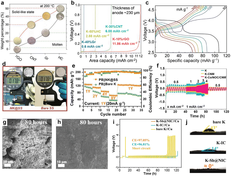 | ||
| Fig. 7 (a) State of composite K metal anodes with different carbon materials and weight percentages at 200 °C. (b) Areal capacities of composite K metal anodes with a thickness of approximately 230 μm in solid-state cells under 0.2 mA cm−2. (c) Voltage vs. specific capacity plots of K-10%rGO||SSE||KxFe[Fe(CN6)] battery. Reproduced with permission from ref. 149. Copyright 2023, Wiley-VCH. (d) Measured thickness of NK based on stainless steel mesh and pure stainless steel. (e) The electrochemical performance of PB||NK@SS and PB||K full batteries. Reproduced with permission from ref. 150. Copyright 2023, Elsevier. (f) Rate performance of the symmetric cells. The surface morphology of the (g) K and (h) K–Co/NOC/CNM after 40 cycles (80 h) in symmetric cells. Reproduced with permission from ref. 151. Copyright 2023, Wiley-VCH. (i) Time–voltage profiles of K–Sb@NIC||Cu, K–IC||Cu, and bare K||Cu half cells at 0.5 mA cm−2/0.5 mA h cm−2. (j) Contact angles between the anodes of K–Sb@NIC, K–IC, bare K, and the electrolyte. Reproduced with permission from ref. 145. Copyright 2024, Wiley-VCH. | ||
Cold rolling is a widely used method for preparing K metal composite anodes. Zhao et al.151 utilized a polyvinylpyrrolidone-assisted carbonaceous nanofiber matrix (CNM) connected with ZIF-67 to enhance the kinetics of the electrode. After high-temperature annealing, they cold-rolled Co-modified N,O co-doped carbon onto the surface of K metal to obtain an integrated anode (K–Co/NOC/CNM). Compared to K–CNM integrating only CNM and K electrodes, the symmetric cell assembled with K–Co/NOC/CNM electrodes exhibited a smaller polarization voltage of 93.0 mV and longer cycle time (Fig. 7f). The effective potassium ion transport guided by the integrated anode resulted in a smoother electrode surface, as observed through SEM after 40 cycles (Fig. 7g and h). Zhou et al.145 designed antimony (Sb) nanoclusters and nitrogen-doped interconnected carbon spheres derived from urea. These materials were repeatedly cold-rolled with K metal to generate a functional anode (K–Sb@NIC). The average CE of the K–Sb@NIC anode after 50 cycles is 97.05%, surpassing the 96.81% efficiency of the K–IC anode without Sb nanoclusters (Fig. 7i). After the establishment of interconnected carbon channels, the wettability improvement between the K–Sb@NIC anode and the electrolyte effectively diminishes the local concentration polarization of K+ (Fig. 7j).
Significant progress has also been made in the development of PMB host materials based on molten K infiltration and electrodeposition of K metal. As shown in Fig. 8, it highlights the representative research works on PMB host materials annually over the past five years. Self-supporting carbon-based host materials have garnered considerable attention due to their excellent electronic conductivity, lightweight, and cost-effectiveness.152 These materials can be further classified into CNTs, rGO, Ti3C2-based composites, carbon nanofibers (CNF), carbon cloth (CC), biomass-derived carbons, carbon spheres, etc.
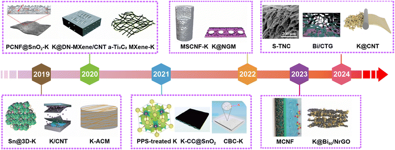 | ||
| Fig. 8 The development of scaffold/host materials for K metal anodes in the past five years. Materials in Fig. 8 are reproduced with permission from ref. 146 (Copyright 2019, American Chemical Society), ref. 153 (Copyright 2019, Wiley-VCH), ref. 154 (Copyright 2019, Wiley-VCH), ref. 81 (Copyright 2020, Royal Society of Chemistry), ref. 155 (Copyright 2020, Wiley-VCH), ref. 156 (Copyright 2020, Royal Society of Chemistry), ref. 157 (Copyright 2021, American Chemical Society), ref. 158 (Copyright 2021, Royal Society of Chemistry), ref. 159 (Copyright 2021, American Chemical Society), ref. 160 (Copyright 2022, Springer Nature), ref. 148 (Copyright 2022, Elsevier), ref. 62 (Copyright 2023, American Chemical Society), ref. 161 (Copyright 2023, Wiley-VCH), ref. 162 (Copyright 2024, American Chemical Society), ref. 163 (Copyright 2024, Elsevier) and ref. 164 (Copyright 2024, Elsevier). | ||
CNTs exhibit superior conductivity, and their unique hollow structure provides ample space for efficient ion transport pathways.154,165 For example, Cheng et al.166 constructed hollow CNTs embedded with Bi nanoparticles (Bi@CNT) through coaxial electrospinning, followed by calcination. SEM images after K deposition unveils that K preferentially deposited inside the Bi@CNT, resulting in a smoother surface without agglomerated K compared to the pristine CNTs (Fig. 9a and b). Thereafter, Cheng et al.167 used cobalt-doped ZIF-8 to obtain hollow carbon tubes (HCT) embedded with CoZn nanoparticles (CoZn@HCT). After infusing molten K, the CoZn@HCT@K symmetric cell exhibits smaller deposition/stripping overpotentials than HCT at varied current densities due to the nucleation sites furnished by the CoZn nanoparticles (Fig. 9c). Recently, Wang et al.162 utilized the potassium-philic nature and capillary force of CNTs to inject molten K into CNT films (K@CNT). The conductive skeleton allows K@CNT to strip a specific capacity of 2.58 mA h cm−2 (Fig. 9d). In situ optical image combined with Raman analysis verify the stripping behavior of metallic K from the edge CNTs to the interior graphite intercalation compounds (GIC; Fig. 9e). Chen et al.168 designed a porous composite host (CNT@ZIF-8) by immersing CNT films into the precursor solution required for ZIF-8 synthesis (Fig. 9f and g). The K@CNT@ZIF-8 symmetric battery, composed of pre-potassiated CNT@ZIF-8 electrodes, demonstrated stability for 3200 h at 0.35 mA cm−2, with a voltage hysteresis of only 18 mV (Fig. 9h).
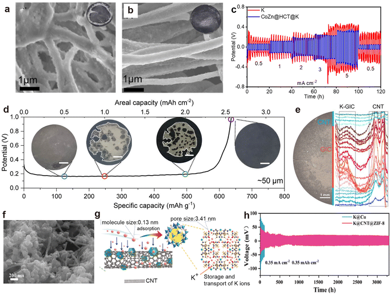 | ||
Fig. 9 SEM images of (a) CNT matrix and (b) Bi@CNT after plating 2![[thin space (1/6-em)]](https://www.rsc.org/images/entities/char_2009.gif) mA h mA h![[thin space (1/6-em)]](https://www.rsc.org/images/entities/char_2009.gif) cm−2 of K metal at 0.5 cm−2 of K metal at 0.5![[thin space (1/6-em)]](https://www.rsc.org/images/entities/char_2009.gif) mA mA![[thin space (1/6-em)]](https://www.rsc.org/images/entities/char_2009.gif) cm−2. Reproduced with permission from ref. 166. Copyright 2022, Elsevier. (c) Rate performance of the CoZn@HCT@K and K symmetric batteries. Reproduced with permission from ref. 167. Copyright 2022, American Chemical Society. (d) Full K stripping curve of K@CNT at 0.5 mA cm−2 in a symmetric cell. The inset shows the morphology evolution of K@CNT after stripping at 0.5, 1, 2, and 2.6 mA h cm−2. (e) Raman line scan results of the K@CNT electrode after stripping at 1 mA h cm−2. Reproduced with permission from ref. 162. Copyright 2024, American Chemical Society. (f) SEM image of CNT@ZIF-8. (g) Schematic illustration of the pre-storage process of potassium ions within CNT@ZIF-8. (h) Cycling performance of symmetric cells employing CNT@ZIF-8 at 0.35 mA cm−2/0.35 mA h cm−2. Reproduced with permission from ref. 168. Copyright 2024, Elsevier. cm−2. Reproduced with permission from ref. 166. Copyright 2022, Elsevier. (c) Rate performance of the CoZn@HCT@K and K symmetric batteries. Reproduced with permission from ref. 167. Copyright 2022, American Chemical Society. (d) Full K stripping curve of K@CNT at 0.5 mA cm−2 in a symmetric cell. The inset shows the morphology evolution of K@CNT after stripping at 0.5, 1, 2, and 2.6 mA h cm−2. (e) Raman line scan results of the K@CNT electrode after stripping at 1 mA h cm−2. Reproduced with permission from ref. 162. Copyright 2024, American Chemical Society. (f) SEM image of CNT@ZIF-8. (g) Schematic illustration of the pre-storage process of potassium ions within CNT@ZIF-8. (h) Cycling performance of symmetric cells employing CNT@ZIF-8 at 0.35 mA cm−2/0.35 mA h cm−2. Reproduced with permission from ref. 168. Copyright 2024, Elsevier. | ||
rGO is composed of a 2D layered carbon structure, possesses a large specific surface area, and easily forms self-supporting films.169,170 These characteristics make rGO a popular material in composite electrode host materials, enhancing electrochemical performance and cycling stability.171,172 Feng et al.161 obtained nitrogen-doped Bi80/rGO through vacuum filtration and a high-temperature amination reduction reaction (Fig. 10a). During the K plating process, no K dendrites are observed on the uniquely designed K@Bi80/NrGO surface, indicating that the designed N and Bi sites effectively guided K nucleation and uniform deposition (Fig. 10b and c). Additionally, Zhang et al.173 employed a composite electrode (rGCA) consisting of CNTs, rGO, and Ag nanoparticles (Fig. 10d), exhibiting remarkable CE in asymmetric batteries, maintaining 93.55% after 140 cycles (Fig. 10e).
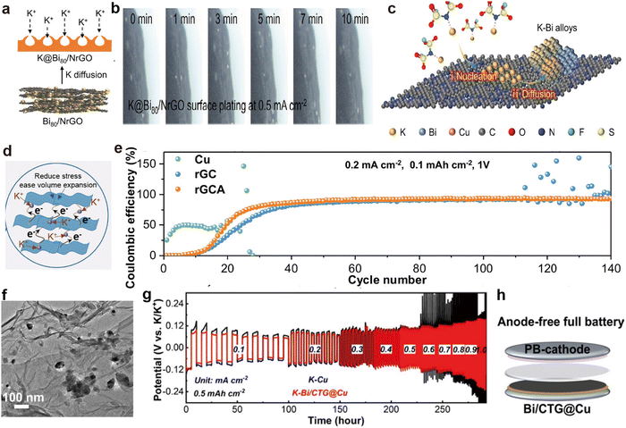 | ||
| Fig. 10 (a) Schematic diagram of K plating on K@Bi80/NrGO. (b) In situ optical microscope images depicting K plating on the K@Bi80/NrGO electrode. (c) Schematic illustration of the possible atomic-level K plating process in the initial process. Reproduced with permission from ref. 161. Copyright 2023, Wiley-VCH. (d) Schematic diagram illustrating the functional structure of rGCA. (e) CE comparison of K||Cu, K||rGC, and K||rGCA half-cells. Reproduced with permission from ref. 173. Copyright 2023, Wiley-VCH. (f) TEM image of Bi/CTG aerogel. (g) Rate performance comparison at diverse current densities. (h) Schematic of the Bi/CTG@Cu||PB battery. Reproduced with permission from ref. 163. Copyright 2024, Elsevier. | ||
Ti3C2, with its 2D layered architecture, high electronic conductivity and chemical stability, is another material commonly used for the preparation of self-supporting K metal scaffold films.155,156 The accordion-like multilayered structure not only increases its specific surface area but also provides excellent flexibility.174,175 Additionally, its surface is rich in functional groups, making the structure highly adjustable.176,177 Zhang et al.163 successfully self-assembled Bi3+ with negatively charged GO and Ti3C2, followed by a solvothermal reaction with CNTs to obtain a novel 3D cross-linked porous aerogel structure (Bi/CTG; Fig. 10f). After K deposition, the symmetric battery composed of the obtained K–Bi/CTG@Cu electrodes exhibits excellent rate capability, characterized by stable overpotential (Fig. 10g). Furthermore, combining Bi/CTG@Cu with the PB cathode enabled the successful construction of anode-free PMBs (Fig. 10h).
Apart from compounding with CNTs, Zhang et al.164 also attempted to crosslink Ti3C2 with chitosan, followed by vulcanization to form ordered porous aerogel (S-TNC). After K deposition, owing to the introduction of potassium affinity sites S and N, the assembled S-TNC@K symmetric battery can cycle for 600 h at 0.5 mA cm−2 (Fig. 11a). Additionally, Zhang et al.178 used the immersion method to construct ZnO-loaded crumpled monolayer Ti3C2 MXene (TZ) on carbonized melamine-derived carbon foam (3D-CF), forming a 3D-CTZ anode. The high potassium affinity of ZnO allows rapid injection of molten K into the 3D-CTZ anode, resulting in the cross-section of the 3D-CTZ@K anode remaining flatter than that of metallic K after 10 min of electrodeposition (Fig. 11b and c). To further achieve uniform potassium ion flux, Zhang et al.179 designed a mixture of high potassium affinity Ti3CN and F-doped SnO2 (TS) as the bottom layer, and used spin coating to achieve a top layer (PKS) composed of dielectric perfluorinated sulfonic acid K and mesoporous silica (Fig. 11d). The potassium-philic sites in the double-gradient structured bottom layer induce uniform deposition of K from bottom to top, while the porous structure and the in situ formed K–Sn alloy with the fluorine-containing SEI layer in the top layer ensure rapid migration of K+ (Fig. 11e). As the current density increased from 0.1 to 1.0 mA cm−2, the TS@K symmetric cell experiences a slight decrease in overpotential due to soft short-circuiting, but the TS-PKS@K symmetric cell maintains normal cycling (Fig. 11f).
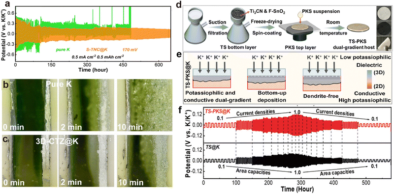 | ||
| Fig. 11 (a) Long-term cycling performance at 0.5 mA cm−2 and 0.5 mA h cm−2. Reproduced with permission from ref. 164. Copyright 2024, Elsevier. In situ optical observation on the surface of (b) pure K and (c) 3D-CTZ@K anodes at 20.0 mA cm−2 during the deposition process. Reproduced with permission from ref. 178. Copyright 2023, Royal Society of Chemistry. (d) Schematic illustration of the preparation process for the dual-gradient free-standing TS-PKS host and digital images of the TS-PKS host. (e) Schematic diagram of the deposition mechanism in the TS-PKS host. (f) Rate capability of symmetric batteries. Reproduced with permission from ref. 179. Copyright 2024, Wiley-VCH. | ||
Porous CNF prepared through electrospinning technology and calcination exhibit excellent electronic conductivity, self-supporting properties and lightweight, making them one of the promising candidates as host materials in PMBs.180–182 Li et al.160 developed nitrogen and zinc co-doped porous CNF (MSCNF) using a zinc-triazole metal organic framework (MET-6). After the injection of molten K, the MSCNF-K symmetric cell exhibited a low average overpotential of about 100 mV, and maintained stable cycling for more than 800 h (Fig. 12a). In addition, the K–S battery composed of a pre-oxidized PAN loaded with Se0.05S0.95 (Se0.05S0.95@p-PAN) cathode and MSCNF-K anode can preserve stable cycling even after varying the current density (Fig. 12b). Anode-free batteries represent the main trend in the development of PMBs, aiming for high energy density and safety.183–185 For instance, Li et al.62 demonstrated the practicality of mesoporous CNF (MCNF) in anode-free PMBs, achieving a capacity retention rate of 86% after 100 cycles (Fig. 12c–e). Chen et al.186 demonstrated that increasing the binding energy between multichannel CNF and metal K by doping non-metallic heteroatom phosphorus (PMCFs) can effectively decrease the critical nucleation size (Fig. 12f). Subsequently, red P was evaporated and deposited on PMCF (P-PMCFs) to further reduce the nucleation barrier of K. When electrodepositing a capacity of 5 μA h cm−2, the surface of P-PMCFs did not exhibit the morphology of K dendrite epitaxial growth and aggregation exhibited by PCMFs (Fig. 12g and h). Consequently, P-PCMFs/Cu asymmetric batteries exhibit the most stable K deposition/stripping behavior at various current densities (Fig. 12i).
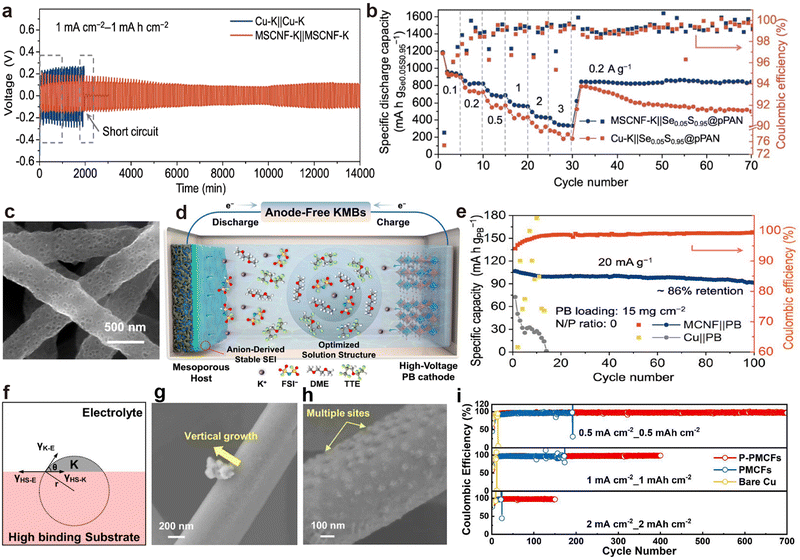 | ||
| Fig. 12 (a) Voltage profiles of symmetric cells. (b) Rate performance of full cells. Reproduced with permission from ref. 160. Copyright 2022, Springer Nature. (c) SEM images of MCNF. (d) Schematic representation of an anode-free MCNF||PB cell. (e) Cycling performance of an anode-free MCNF||PB cell. Reproduced with permission from ref. 62. Copyright 2023, American Chemical Society. (f) Schematic illustration of K nucleation on substrate with high binding energy toward K. SEM images of K nucleation and growth morphology on (g) PMCFs and (h) P-PMCFs after K plating at 1 mA cm−2 with 5 μA h cm−2. (i) CE of K plating/stripping on PMCFs, P-PMCFs, and Cu. Reproduced with permission from ref. 186. Copyright 2024, American Chemical Society. | ||
Carbon cloth (CC) has high tensile strength, high modulus, and excellent conductivity, along with flexibility and processability similar to textile fibers.158,187 To reduce the nucleation barrier of metallic K, surface modification techniques can be divided into functional group modification and potassium-affinity material composites. Meng et al.188 achieved NH3-functionalization CC by soaking in ammonia water, allowing the molten K to diffuse along the CC fibers within 4 s to form a composite anode (K@CC; Fig. 13a and b). Li et al.189 obtained oxygen-modified CC (O-CC) through air heat treatment. Due to the high electron density near the epoxy groups (Fig. 13c), the rapid injection of molten K was successfully achieved. Compared with the pristine CC (P-CC), the Fermi level of O-CC is significantly reduced to −2.84 eV, much lower than the LUMO level of the electrolyte (Fig. 13d). This change effectively diminishes side reactions and improvs the stability and safety of the battery.
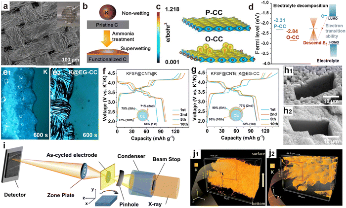 | ||
| Fig. 13 (a) SEM images of K@CC. The inset is a digital photo of the freestanding K@CC. (b) Schematic illustration of greatly improved wettability of K metal on the functionalized CC. Reproduced with permission from ref. 188. Copyright 2022, American Chemical Society. (c) Charge density plots and (d) surface Fermi levels of P-CC and O-CC. Reproduced with permission from ref. 189. Copyright 2023, Royal Society of Chemistry. In situ optical microscopy visualization of (e1) the bare K electrode and (e2) the K@EG-CC electrode. Charge/discharge profiles of (f) the KFSF@CNTs||K cell and (g) the KFSF@CNTs||K@EG-CC cell. Reproduced with permission from ref. 190. Copyright 2024, Wiley-VCH. Cryo-FIB SEM images of (h1) baseline Cu and (h2) FCC anodes. (i) X-ray nano-tomography setup at the FXI beamline, NSLS-II. 3D volume rendering of K plated on (j1) Cu and (j2) FCC substrates. Reproduced with permission from ref. 191. Copyright 2023, Wiley-VCH. | ||
Our group further found that carbonyl modified CC (EG-CC) treated with ethylene glycol (EG) can achieve uniform K infiltration within 3 s (K@EG-CC).190 Optical microscope images confirmed that the K@EG-CC electrode did not exhibit obvious K aggregation similar to that on the K surface after 600 s of electroplating (Fig. 13e). The PMB composed of a high-voltage KFeSO4F interwoven with carbon nanotubes (KFSF@CNTs) cathode and a K@EG-CC anode exhibits more reversible charge–discharge behavior and higher CE compared to a battery composed of a metal K anode (Fig. 13f and g). Liu et al.191 studied the K deposition behavior on non-wettable surfaces (Cu foil) and oxygen-enriched functionalized carbon cloth (FCC) surfaces using cryogenic-focused ion beam (cryo-FIB) cross-sectional SEM and synchrotron X-ray imaging (Fig. 13i). Clear dendritic K crystals appeared on the surface of the Cu foil, and a large number of cracks and voids caused by uneven deposition were also observed in 3D imaging (Fig. 13h1 and j1). The surface of FCC is dense, and K is evenly distributed on the surface of CC fibers (Fig. 13h2 and j2), confirming that the interaction between the matrix and K metal plays a key role in the nucleation and growth of K metal.
Regarding the growth of potassium-friendly materials on the CC surface, it is usually necessary to first acidify commercial CC to increase its surface oxygen-containing functional groups, and then achieve material growth through solvothermal methods. Fei et al.192 first reported that the modification of MoC particles on CC (α-MoC@CC) and their affinity with K metal (Fig. 14a). After infiltration with molten K, the K@α-MoC@CC anode was obtained (Fig. 14b). Severe side reactions on the bare K surface led to a decrease in the interfacial resistance of the bare K anode after cycling compared to the initial value, but it remains higher than that of K@α-MoC@CC (Fig. 14c and d). Xia et al.193 used ZnO rods grown on the surface of CC as templates, and then loaded a layer of potassium-affinity nitrogen-doped carbon (NC) layer (Fig. 14e). Due to the higher binding energy between K and NC-modified carbon compared to that between K and carbon (Fig. 14f), the introduction of NC/ZnO nanorods effectively reduces the nucleation barrier of K. The K@NC/ZnO@CC symmetric batteries exhibited the lowest overpotential at current densities ranging from 0.5 to 5 mA cm−2 (Fig. 14g). Our group designed interconnected porous NiO to grow on the surface of CC (CC-NiO; Fig. 14h), successfully achieving rapid infiltration of molten K into CC-NiO electrodes within 1 s.194 This discovery is attributed to the higher charge transfer number between K and NiO (0.85e) compared to K and the carbon layer (0.73e) (Fig. 14i and j). The increased potassium-affinity surface and porous architecture markedly enhance the charge transfer kinetics of the K@CC-NiO electrode compared to bare K (Fig. 14k).
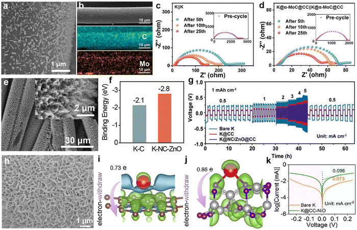 | ||
| Fig. 14 (a) SEM images of α-MoC@CC. (b) SEM and EDS elemental mappings of a single α-MoC@CC composite fiber. Electrochemical impedance spectroscopy (EIS) spectra of (c) K||K and (d) K@α-MoC@CC|K@α-MoC@CC symmetric batteries. Reproduced with permission from ref. 192. Copyright 2024, Elsevier. (e) SEM images of NC/ZnO@CC. (f) Adsorption energies of K metal on different substrates calculated using density functional theory (DFT). (g) Rate performance comparison. Reproduced with permission from ref. 193. Copyright 2024, Royal Society of Chemistry. (h) SEM image of CC–NiO. Charge density differences between K and (i) carbon layer and (j) NiO using Bader charge analysis. (k) Tafel curves of K@CC–NiO and bare K symmetric cells. Reproduced with permission from ref. 194. Copyright 2024, Elsevier. | ||
Biomass typically consists of plant fibers, proteins, and sugars, which are rich in carbon, nitrogen, and oxygen.159,195 The derived materials are usually nitrogen-rich carbon matrices, serving as advanced host materials. Lu's group demonstrated a low-tortuosity N-doped carbon matrix (HC) derived from treated birch trunks (Fig. 15a), which retained the directional channels of the wood itself and was decorated with single atom Co (SA–Co@HC).196 The assembled SA–Co@HC/K symmetric battery exhibited no obvious dendrites on the electrode surface, and the voltage hysteresis increased steadily without drastic fluctuations as the current density increased to 5 mA cm−2 (Fig. 15b). Subsequently, the same group prepared oxygen-functionalized porous carbon microribbons (OPCMs) with carbon nanospheres distributed within.197 The abundant oxygen and benzene ring structures strongly interact with K, thereby promoting K nucleation (Fig. 15c). The K-OPCMs anode, obtained after K deposition, paired with perylene-3,4,9,10-tetracarboxylic dianhydride (PTCDA) in a metal battery, maintained a reversible capacity of 97.8 mA h g−1 after 1600 cycles at 2000 mA g−1 (Fig. 15d). Shen et al.198 prepared nitrogen and oxygen-doped graphitic carbon matrix (NOGC) materials decorated with NiCo, NiFe, and CoFe alloy particles through hydrothermal treatment of leaves and nitrates, followed by high-temperature processing (Fig. 15e). Among them, the NiCo@NOGC electrode retained a smooth surface after K deposition/stripping cycles, while bare K showed obvious protrusions (Fig. 15f and g). The NiCo@NOGC symmetric batteries also delivered the longest stable cycle time and the lowest overpotential (Fig. 15h).
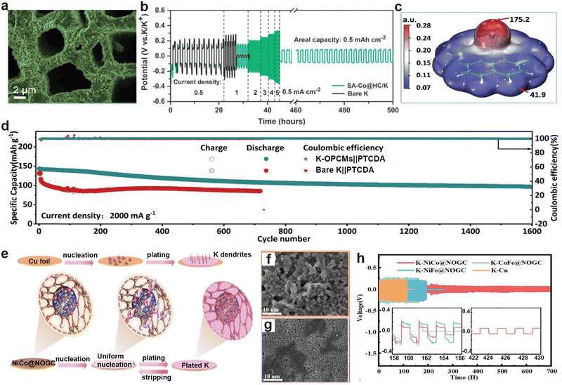 | ||
| Fig. 15 (a) SEM image of plated K on SA–Co@HC host at 0.5 mA cm−2 and 8 mA h cm−2. (b) Voltage profiles of the symmetric cells at diverse current densities under a fixed areal capacity of 0.5 mA h cm−2. Reproduced with permission from ref. 196. Copyright 2022, Wiley-VCH. (c) Molecular surface electrostatic potential isosurface (isovalue = 0.001 e Bohr−3). (d) Cycle performance comparison. Reproduced with permission from ref. 197. Copyright 2023, Wiley-VCH. (e) Schematic illustration depicting the K plating/stripping behaviors on the NiCo@NOGC substrate. SEM images of (f) Cu and (g) NiCo@NOGC electrodes after plating at 2 mA h cm−2. (h) Voltage profiles of K–NiCo@NOGC symmetric cells. Reproduced with permission from ref. 198. Copyright 2023, Royal Society of Chemistry. | ||
Ye et al.199 observed that dendrite growth on K metal anodes might be affected by the potassium ion diffusion process. They designed hollow open mesoporous carbon spheres (OMSs) with fast ion channels and synthesized hollow discontinuous microporous carbon spheres (DMSs) for comparison (Fig. 16a and b). In situ K plating experiments unraveled that the open mesoporous channels served as deposition sites for K (Fig. 16c). In contrast, K+ diffusion in DMSs was slower, leading to deposition on the carbon sphere surface. Additionally, Ding et al.200 synthesized a biomimetic virus-like carbon microsphere (BVC) as a host material for K metal by growing CNTs on the surface of carbon spheres (Fig. 16d). The CNTs on the surface of the BVC made the local current density more uniform, and the electric field distribution of the carbon spheres ensured uniform ion distribution across the entire outer surface (Fig. 16e). The graphene film electrode dispersed with BVC after molten K infiltration (K-BVC) maintained a flat surface during K deposition (Fig. 16f). The K metal battery matched with a PB cathode exhibited a specific capacity of 88.4 mA h g−1 at 3 A g−1 (Fig. 16g). Table 2 shows the symmetric battery performance of PMB host materials in the recent years.
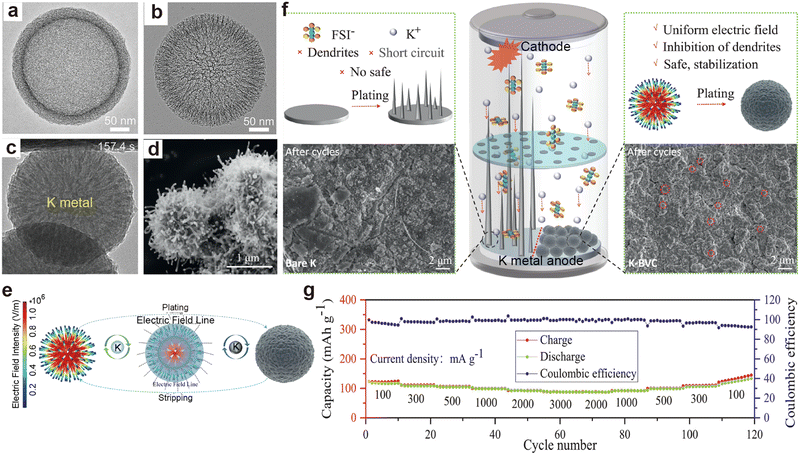 | ||
| Fig. 16 TEM images of (a) DMSs and (b) OMSs. (c) In situ microscopy observation of superfast K plating in the cavity of an OMS. Reproduced with permission from ref. 199. Copyright 2023, Wiley-VCH. (d) SEM image of BVC. (e) Simulation models of electric field values and the plating/stripping process of K metal. (f) Top-view SEM images of K deposition onto bare K and K-BVC at 0.1 mA cm−2 with a plating capacity of 0.1 mA h cm−2. (g) Rate capability of the K-BVC/PB full cell. Reproduced with permission from ref. 200. Copyright 2023, Elsevier. | ||
| Material | Current density (mA cm−2) | Capacity (mA h cm−2) | Cycling life (h) | Ref. |
|---|---|---|---|---|
| K@Bi@CNT | 0.5 | 0.5 | 500 | 166 |
| CoZn@HCT@K | 1 | 1 | 1000 | 167 |
| K@CNT | 1 | 1 | 222 | 162 |
| K@CNT@ZIF-8 | 0.35 | 0.35 | 3200 | 168 |
| K@Bi80/NrGO | 0.2 | 0.1 | 3000 | 161 |
| rGCA-K | 0.2 | 0.2 | 1600 | 173 |
| K–Bi/CTG | 0.5 | 0.5 | 550 | 163 |
| S-TNC@K | 0.5 | 0.5 | 600 | 164 |
| 3D-CTZ@K | 1 | 1 | 830 | 178 |
| TS-PKS@K | 0.5 | 0.5 | 2800 | 179 |
| MSCNF-K | 1 | 1 | 233 | 160 |
| MCNF | 1 | 1 | 1000 | 62 |
| K@P-PMCFs | 0.5 | 0.5 | 3200 | 186 |
| NH3 K@CC | 1 | 1 | 350 | 188 |
| O-CC@K | 1 | 0.5 | 3500 | 189 |
| K@EG-CC | 0.5 | 0.5 | 2000 | 190 |
| K@FCC | 0.5 | 0.5 | 300 | 191 |
| K@α-MoC@CC | 0.5 | 0.5 | 2000 | 192 |
| K@NC/ZnO@CC | 1 | 1 | 700 | 193 |
| K@NiO–CC | 0.4 | 0.4 | 1840 | 194 |
| SA–Co@HC/K | 1 | 1 | 900 | 196 |
| K-OPCMs | 3 | 3 | 280 | 197 |
| K–NiCo@NOGC | 0.2 | 0.2 | 700 | 198 |
| K-BVC | 0.5 | 0.5 | 1000 | 200 |
| Material | Symmetric cell | Full cell | Ref. | ||
|---|---|---|---|---|---|
| Current density (mA cm−2)/Capacity (mA h cm−2) | Overpotential (mV)/cycle time (h) | Cathode | Current density (mA g−1)/cycle number | ||
| Cu6Sn5 | 1/1 | 70/600 | PTCDA (anode-free) | 20/30 | 204 |
| Cu–OSe NWs | 1/1 | 35/950 | K0.5MnO2 (anode-free) | 100/200 | 205 |
| Cu1.4Te | 1/4 | 11/800 | Te (pouch) | 33/30 | 206 |
| Cu3Pt–Cu mesh | 0.5/1 | 1000/300 | PB | 100/270 | 207 |
| Pd/Cu | 1/1 | 500/130 | PB | 150/60 | 208 |
| KSEC | 1/1 | 80/1000 | PTCDA | 600/600 | 209 |
| Cu@Sb2O3@rGO | 0.2/0.2 | 25/1300 | PTCDA | 1100/2000 | 210 |
| Al@Al foil | 0.5/0.5 | 85/1000 | — | — | 211 |
| NC@GDY-Al | 2/2 | 3/2400 | KPB | 1000/200 | 212 |
| Al@G | 0.5/0.5 | 42/1000 | FeS2 (anode-free) | 100/30 | 213 |
| NG@P-Al@K | 50/1 | 608/400 | KPB | 100/400 | 214 |
3.1.3.1. Modified Cu foil current collectors. As a typical current collector for alkali metal batteries, commercial Cu foil lacks potassiophilic nucleation sites and exhibits high nucleation resistance, leading to the generation of numerous K dendrites during the K plating/stripping processes.191 This can severely impact the performance of PMBs and may even pose safety risks.215,216 One approach to enhance the potassium affinity of Cu foil is through modification, such as the method employed by Ren et al.204 They constructed a Cu-based alloy Cu6Sn5 layer, which has the highest adsorption energy (−4.98 eV) for K, on commercial Cu foil through a chemical plating process. Thanks to the uniform K nucleation, K deposits evenly on Cu6Sn5@Cu compared to bare Cu (Fig. 17a and b). Cu6Sn5 can effectively induce dense K deposition, and the thickness of K deposited on Cu6Sn5@Cu (54 μm) is much smaller than that on pure Cu (87 μm) (Fig. 17c and d). Consequently, the reservoir-free half-cell using Cu6Sn5@Cu can achieve exceptional cycle stability of up to 600 h and an average CE of 99.69% (Fig. 17e). Due to the improvement of CE of the Cu6Sn5@Cu anode, after 30 cycles, the anode-free battery assembled with PTCDA showed a capacity retention rate of 69.4%, which is much higher than that of unmodified Cu (43.4%) (Fig. 17f).
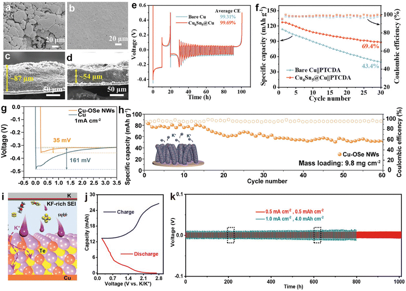 | ||
| Fig. 17 SEM images of K electrodeposition on (a) bare Cu and (b) Cu6Sn5@Cu. Cross-sectional SEM images of K electrodeposition on (c) bare Cu and (d) Cu6Sn5@Cu with a capacity of 2 mA h cm−2. (e) CE of bare Cu and Cu6Sn5@Cu current collectors at 1 mA cm−2 with a capacity of 1 mA h cm−2. (f) Cyclic performance of bare Cu||PTCDA and Cu6Sn5@Cu||PTCDA anode-free full cells at 20 mA g−1. Reproduced with permission from ref. 204. Copyright 2024, Wiley-VCH. (g) Voltage profiles of K nucleation at 1 mA cm−2. (h) Cycling performance of the anode-free K0.5MnO2||Cu–OSe NWs full cell at 100 mA g−1. The inset shows a schematic of K deposition behavior on Cu–OSe NWs. Reproduced with permission from ref. 205. Copyright 2024, Elsevier. (i) Cross-sectional schematic diagram displaying the interior configuration of PMBs. (j) Typical charge/discharge profiles at 0.1 mA cm−2 and −40 °C. (k) Galvanostatic cycling performance of K||K symmetric cells with 0.5 M KPF6/DME-3TTE. Reproduced with permission from ref. 206. Copyright 2022, Wiley-VCH. | ||
Similarly, Cui et al.205 developed Cu nanowires (Cu–OSe NWs) with Cu–OSe bonds through a strategy of partial selenization of hydroxide nanowires. The potassium-friendly Cu–OSe bonds on the surface of these nanowires have abundant nucleation sites, which help accelerate the kinetics of K+. The nucleation potential of K||Cu–OSe NWs asymmetric cells (below 35 mV) is much lower than that of K||Cu (161 mV; Fig. 17g). As a result, the anode-free PMB composed of Cu–OSe NWs and K0.5MnO2 maintains a high capacity of 58.7 mA h g−1 with a retention rate of 76% even after 60 cycles, when the cathode loading is increased to 9.8 mg cm−2 (Fig. 17h). Besides pre-modifying Cu foil through chemical methods, Chen et al.206 coated tellurium (Te) on the surface of the Cu foil and reversibly constructed amorphous Cu1.4Te and Cu in situ (Fig. 17i). For the first time, micro-sized Te was directly used as the cathode material, and the assembled K–Te pouch cell maintained a high capacity of 14.2 mA h after 30 cycles at −40 °C (Fig. 17j). In addition, this work added 1,1,2,2-tetrafluoroethyl-2,2,3,3-tetrafluoropropane (TTE) to KPF6-DME electrolyte to form a KF-rich SEI (Fig. 17i). The assembled K||K symmetric cell confirmed that the electrolyte optimization improved cycling stability even at a high areal capacity of 4.0 mA h cm−2 (Fig. 17k).
3.1.3.2. 3D Cu current collectors. The 3D porous skeletal structure of Cu mesh or foam provides sufficient space and specific surface area, which can relieve the volume expansion of K metal and reduce local current density.217,218 However, due to the potassium-phobic nature of the 3D Cu surface, K grains may agglomerate during the deposition process, leading to uneven electric fields and the formation of K dendrites.188 Therefore, structural modulation of 3D Cu is an effective strategy to enhance the stability of PMBs. For instance, Wang et al.207 achieved the formation of a Cu3Pt layer on Cu mesh through a galvanic replacement reaction (Fig. 18a). SEM images show that compared to smooth Cu mesh, the Cu3Pt–Cu surface after the reaction exhibits a large number of Cu3Pt nanoparticles (Fig. 18b–e), which can reduce the nucleation barrier and offer a uniform electric field distribution. A punch press was used to press metal K onto the surface of the current collector, forming a K@ Cu3Pt–Cu electrode. The K@ Cu3Pt–Cu symmetric cell achieved a cycle life of over 170 h at a capacity of 5 mA h cm−2, outperforming other reports under the same conditions (Fig. 18f). Afterwards, the same group coated the surface of highly plastic Cu foam with a more potassiophilic layer of Pd through a replacement reaction in liquid-phase synthesis, forming a Pd/Cu foam current collector (Fig. 18g).208 The potassiophilic Pd allows for dense deposition of K and significantly enhances the stability of the interface. The K asymmetric battery made from Pd/Cu foam also demonstrated a cycling CE close to 100% at a high capacity of 10 mA h cm−2, and the K/Pd/Cu||PB full battery maintains a high-capacity retention rate of 97% after 60 cycles at −20 °C (Fig. 18h).
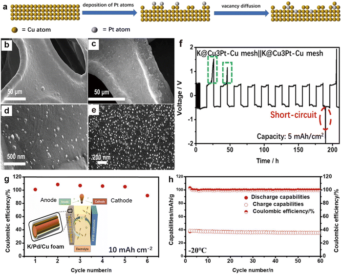 | ||
| Fig. 18 (a) Process of galvanic replacement reaction. SEM images of (b) and (d) Cu mesh and (c) and (e) Cu3Pt–Cu mesh. (f) Voltage–time profiles of K@Cu3Pt–Cu mesh||K@Cu3Pt–Cu mesh at a current density of 0.5 mA cm−2 with a capacity of 5 mA h cm−2. Reproduced with permission from ref. 207. Copyright 2020, Elsevier. (g) CE of K plating/stripping on Pd/Cu foam at a current density of 0.5 mA cm−2 with an area capacity of 10 mA h cm−2. The inset shows the schematic illustration of K/Pd/Cu||PB battery. (h) Cycling property of the K/Pd/Cu||PB full battery at 150 mA g−1 at −20 °C. Reproduced with permission from ref. 208. Copyright 2022, Elsevier. | ||
In addition, some non-precious metals are used to build potassiophilic substances on the Cu foam to reduce costs. Due to the high electronic conductivity of the Cu foam, if the 3D skeleton cannot achieve a uniform distribution of potassium sites, it will result in a limited diffusion path of K+, causing metallic K to deposit on the surface of the Cu foam. Jiang et al.209 introduced a layer of CuSe onto the Cu foam through selenium (Se) thermal evaporation, realizing simultaneous deposition of K at the top and bottom of the framework (Fig. 19a). Even at a low temperature of −20 °C, the anode surface of K2Se/Cu@Cu foam (KSEC) can still grow uniformly without forming granular dead K on the K2S/Cu@Cu foam (KSC) surface (Fig. 19b and c). Furthermore, the full battery composed of a PTCDA cathode exhibits a cycle life of over 600 cycles at low temperatures (Fig. 19d). Qi et al.210 developed a multifunctional interface (Cu@Sb2O3@rGO) that incorporates potassiophilic Sb2O3 from the displacement reaction between SbCl3 and rGO on Cu foam (Fig. 19e–g). rGO can provide more defects, promote the homogenization of potassium ion flux, and effectively reduce the potassium nucleation barrier by combining with Sb2O3. This multifunctional interface synergistically inhibits the formation of K dendrites, enabling the full battery to maintain a high reversible capacity of 72.4 mA h g−1 after 100 cycles at −20 °C (Fig. 19h).
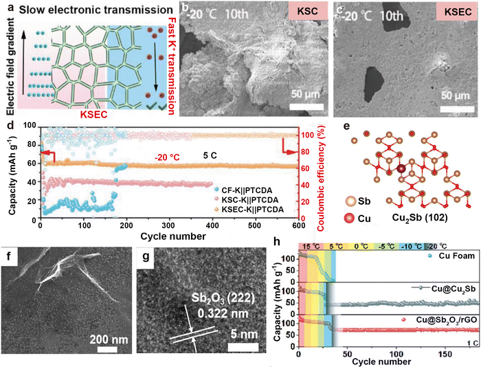 | ||
| Fig. 19 (a) The mechanism of K on KSEC anode. Top-view SEM images of (b) KSC and (c) KSEC anodes after 10 cycles at −20 °C. (d) Cycling capacity curves of Cu foam-K||PTCDA, KSC-K||PTCDA, and KSEC-K||PTCDA full cells at −20 °C. Reproduced with permission from ref. 209. Copyright 2023, Wiley-VCH. (e) The adsorption configurations of K atoms absorbed on Cu2Sb. (f) SEM image and (g) HRTEM image of Cu@Sb2O3@rGO. (h) Temperature degradation test curves for Cu foam@K||PTCDA, Cu@Cu2Sb@K||PTCDA, and Cu@Sb2O3@rGO@K||PTCDA full cells at 110 mA g−1. Reproduced with permission from ref. 210. Copyright 2024, Royal Society of Chemistry. | ||
3.1.3.3. Modified Al current collectors. Al foil is inexpensive and has a low density, making it a commonly used current collector in batteries. Nevertheless, due to its reactivity with lithium, it cannot be used as the current collector in lithium-ion batteries and lithium metal batteries.219 In PMBs, K does not form alloys with Al, but the application of Al foil in PMBs is a relatively recent development due to its low adsorption energy (−0.51 eV) of potassium on Al foil.155 In 2020, Liu et al.211 first proposed the use of Al-based current collectors as alternatives to Cu-based ones. They coated the surface of Al foil with 3D Al powder through sintering to increase its wettability with electrolyte and reduce the overpotential of K plating. Based on this, Yi et al.212 employed nitrogen-doped carbon and coated the surface of Al current collectors with pre-grown graphdiyne to form a thin and lightweight modified layer (NC@GDY-Al; Fig. 20a). The modified layer is used to increase electrolyte wettability, while the attachment of Cu quantum dots loaded with GDY enhances the binding strength of K+. The battery using the NC@GDY-Al electrode, after K electrodeposition (K@NC@GDY-Al), exhibited a cycle life exceeding 2400 h (Fig. 20b).
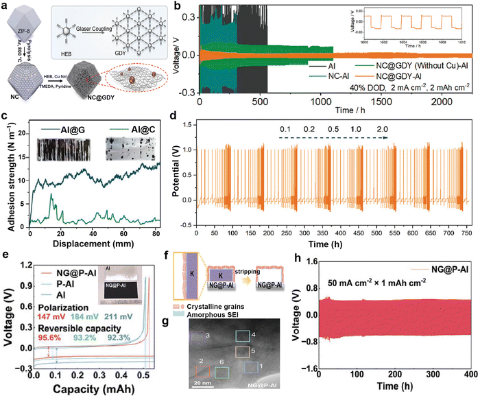 | ||
| Fig. 20 (a) Schematic for the synthetic steps of NC@GDY. (b) Cyclic stabilities of symmetric cells with different electrodes at 2.0 mA cm−2/4.0 mA h cm−2. Reproduced with permission from ref. 212. Copyright 2022, Wiley-VCH. (c) Force–displacement curves of the mechanical peeling-off tests of modified layer. The inset shows optical photos of Al@G and Al@C after mechanical peeling-off tests. (d) Voltage profiles of K plating/stripping on Al@G under periodic current fluctuations from 0.1 to 2.0 mA cm−2. Reproduced with permission from ref. 213. Copyright 2022, Wiley-VCH. (e) Electrochemical K plating/stripping curves of NG@P–Al, P–Al, and Al at 0.5 mA cm−2. The inset is photograph of bare and modified Al current collectors. (f) Schematic diagram of SEI formation on NG@P–Al (g) High-magnification view of the SEI formed over NG@P–Al. (h) Cyclic performance of NG@P–Al-based symmetric cell at 50 mA cm−2/1.0 mA h cm−2. Reproduced with permission from ref. 214. Copyright 2024, Wiley-VCH. | ||
However, the adhesive used in the coating layer may consume K sources. Based on the thin film growth model, Zhao et al.213 adopted a roll-to-roll plasma-enhanced chemical vapor deposition (PECVD) process to grow an ultrathin graphene layer in situ on Al foil (Al@G). Compared to carbon-coated Al foil (Al@C), the graphene-modified layer has a stronger adhesion force of 10.52 N m−2, and its ultra-thin properties can minimize K loss (Fig. 20c). Under periodic current fluctuations ranging from 0.1 to 2.0 mA cm−2, it exhibits excellent stability and high reversibility, with a cycling duration of up to 750 h (Fig. 20d). To further enhance the performance of Al current collector, Lian et al.214 used microwave-assisted pretreatment and subsequent PECVD growth to design a 3D porous nitrogen-doped graphene-modified Al current collector (NG@P–Al). Due to the electronegativity discrepancy between C and Al, electrons are preferentially transported to the electrolyte salt, forming an inorganic-rich SEI (Fig. 20e–g). Batteries based on this designed current collector achieved high-rate performance at 50 mA cm−2, maintaining for 400 h, and could still operate normally at low temperatures of −50 °C (Fig. 20h).
3.2. Interface engineering
It is well known that SEI is comprised of organic and inorganic substances, exhibiting ion conductivity but electronic insulation. Cui's group pioneeringly developed a cryogenic electron microscopy testing method to avoid the destruction of lithium metal by air and conventional TEM electron beams.220 By depositing lithium on copper grids and transferring it after freezing in liquid nitrogen, combined with low electron dose spherical aberration corrected TEM, atomic resolution imaging of lithium metal dendrites and the SEI was successfully achieved. The SEI components on lithium metal surfaces mainly include Li2O, Li2CO3, LiF, and polymers, but the understanding of SEI on K metal surfaces is limited.In recent years, researchers have conducted in-depth investigations on the composition and formation mechanism of potassium-based SEI and found great differences compared to lithium-based SEI. For example, Zhang et al.221 obtained atomic resolution images of potassium-based SEI using aberration-corrected cryo-TEM technology. Fig. 21a displays the cryo-TEM image of K dendrites obtained after 1 h of electrochemical deposition of K metal onto a copper grid. By identifying the inorganic crystals in the SEI produced in KFSI-TEP/2 wt% VC electrolyte (where VC is vinylene carbonate, and TEP is triethyl phosphate), they verified that the potassium-based SEI consists of multiple crystal patches, such as KPO3, K2O, KO2, K2SO4, and K2(SO2)3, as well as amorphous components (Fig. 21b). In carbonate electrolytes, they discovered more metastable products, such as K4CO4, which are different from lithium-based SEI.
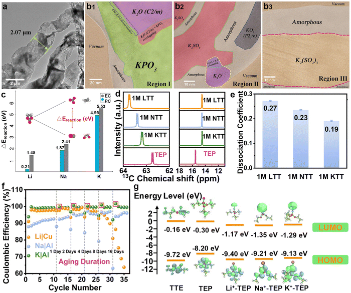 | ||
| Fig. 21 (a) Cryo-TEM image of K dendrites in KFSI-TEP/2 wt% VC. (b) HRTEM images of different regions. Reproduced with permission from ref. 221. Copyright 2021, Wiley-VCH. (c) Comparison of the energetic preference of the CO3 forming reaction between the tested metal surfaces. Reproduced with permission from ref. 222. Copyright 2023, Wiley-VCH. (d) The 13C-NMR spectra of methylene CH2 groups (left) and methyl CH3 groups (right) in TEP. (e) Dissociation coefficient of the corresponding electrolytes. (f) CE of the Li||Cu, Na||Al, and K||Al cells after various aging durations. (g) The energy levels of the LUMO and HOMO from quantum chemistry calculation for electrolyte components. Reproduced with permission from ref. 223. Copyright 2024, Royal Society of Chemistry. | ||
Stottmeister et al.222 compared the initial decomposition mechanisms of solvents during the formation of lithium, sodium, and potassium SEI through ab initio molecular dynamics simulations. Molecular dynamics shows that EC and propylene carbonate (PC), after being adsorbed on alkali metal surfaces, eventually form carbon monoxide or carbonate, but carbon monoxide has not been detected on K surfaces. As shown in Fig. 21c, the difference in reaction energies between the different decomposition pathways of EC and PC on alkali metals indicates a significant energy difference between the formation pathways of CO3 and CO on K, suggesting its tendency to decompose into carbonates on the surface of K. Wang et al.223 proposed through experimental analysis and theoretical calculations that the Lewis acidity of metal ions is closely related to the production of SEI. They dissolved 1 M LiFSI, NaFSI, and KFSI in a mixture of TEP and TTE (volume ratio 1![[thin space (1/6-em)]](https://www.rsc.org/images/entities/char_2009.gif) :
:![[thin space (1/6-em)]](https://www.rsc.org/images/entities/char_2009.gif) 1) to form three electrolytes (LTT, NTT, and KTT). The 13C nuclear magnetic resonance (13C-NMR) spectra show that the interaction between K+ and TEP molecules is the weakest (Fig. 21d), which results in more FSI− in the solvation sheath of potassium ions, leading to the lowest dissociation coefficient of KTT (Fig. 21e). In addition, from the LUMO energy levels of alkali metal ions and TEP complexes, the solvents in NTT are more easily reduced than in KTT, forming an organic-rich SEI. Because potassium ions easily desolvate and the solvents are difficult to reduce, K metal exhibits a more stable SEI structure in phosphate electrolytes compared to sodium and lithium (Fig. 21f and g).
1) to form three electrolytes (LTT, NTT, and KTT). The 13C nuclear magnetic resonance (13C-NMR) spectra show that the interaction between K+ and TEP molecules is the weakest (Fig. 21d), which results in more FSI− in the solvation sheath of potassium ions, leading to the lowest dissociation coefficient of KTT (Fig. 21e). In addition, from the LUMO energy levels of alkali metal ions and TEP complexes, the solvents in NTT are more easily reduced than in KTT, forming an organic-rich SEI. Because potassium ions easily desolvate and the solvents are difficult to reduce, K metal exhibits a more stable SEI structure in phosphate electrolytes compared to sodium and lithium (Fig. 21f and g).
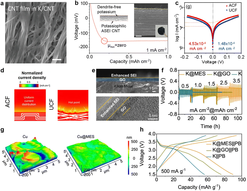
In terms of carbon coverage, various forms of carbon form intercalation compounds through the pre-embedding of potassium ions, further regulating the nucleation and deposition behavior of K. Wang et al.153 spontaneously contacted metallic K foil with a CNT film in the electrolyte (Fig. 22a), resulting in the generation of intercalation compounds between CNTs and K, and the spontaneous production of an SEI layer (K/CNT) on the surface of CNT film. This K-doped CNT interface exhibits high affinity with metallic K, allowing K to have a low nucleation barrier during deposition and to be uniformly distributed in the CNTs (Fig. 22b).
 | ||
| Fig. 22 (a) Top-view SEM image of the CNT film in K/CNT after 20 h of contact. (b) Analysis of potassium nucleation overpotential on artificial SEI (ASEI) CNT rested for 20 h, measured at a fixed current density of 1 mA cm−2. The inset shows the SEM image after deposition and the concerned schematic. Reproduced with permission from ref. 153. Copyright 2019, Wiley-VCH. (c) Tafel plots of the K-ACF||K-ACF and K-UCF||K-UCF cells. (d) Normalized local current density profiles near ACF and UCF. Reproduced with permission from ref. 224. Copyright 2022, Elsevier. (e) SEM image of K@MES and TEM image of the enhanced SEI. (f) Voltage profiles of symmetric cells at various current densities. (g) AFM images of the Cu foil surface and Cu@MES. (h) Charge/discharge voltage profiles of the K@MES||PB, K@GO||PB, and K||PB full cells. Reproduced with permission from ref. 225. Copyright 2023, Springer Nature. | ||
Xiao et al.224 conducted a comparative study to explore the effects of aligned carbon fibers (ACF) and non-aligned carbon fibers (UCF) on the subsequent electroplating/stripping behavior on the surface of K metal after potassium oxidation. Due to the high electronic conductivity of carbon materials, ACF exhibits an exchange current density of up to 4.53 × 10⁻⁴ mA cm−2 (Fig. 22c). In addition, nonlinear phase field simulations predict that a more uniform local current distribution on the surface modified with ACF is beneficial for the uniform deposition of K (Fig. 22d). Ding et al.225 used rolling technology to transfer fluorine doped graphene oxide onto the alkali metal surface, and during the cycling process, a fluorine-rich SEI was formed on the alkali metal surface (Fig. 22e). The biomimetic layer with skin-like properties (metal electrode skin; MES) makes the surface of the K metal electrode smoother, and the symmetric battery composed of it exhibits stable electroplating/stripping voltage curves at varied current densities (Fig. 22f and g). A flat electrode surface helps to form a uniform electric field, while a stable interface enables the full battery composed of K@MES and PB to maintain the highest specific capacity after 500 cycles (Fig. 22h).
Pretreatment of K in electrolytes is one of the effective methods for in situ formation of a uniform SEI, which has a significant passivation effect on K metal surfaces. Hamada et al.226 spontaneously formed a passivation layer in situ on the surface of K metal by immersing the pretreated K metal in a KFSA/DME electrolyte of containing 1,3,2-dioxathiohexane 2,2-dioxide (DTD). The K symmetric battery treated with solid polymer electrolyte (SPE) exhibits a hysteresis voltage of about 500 mV (Fig. 23a), which is much lower than the untreated K metal battery (>1 V). The all-solid-state battery composed of treated K retains a capacity retention rate of up to 98% after 10 cycles (Fig. 23b). Gu et al.227 assembled a K symmetric battery using a functionalized ionic liquid monomer, 1-allyl-3-vinylimidazolium bis (fluorosulfonyl) imide (AVIIMFSI), as the electrolyte. During the cycling process, the functional groups on AVIIMFSI receive electrons and undergo in situ electro polymerization (ISEP) on the K metal surface to generate a uniform and highly elastic SEI (Fig. 23c). The PB||K battery benefits from excellent ISEP-SEI, and its specific capacity does not show obvious degradation after 400 cycles (Fig. 23d).
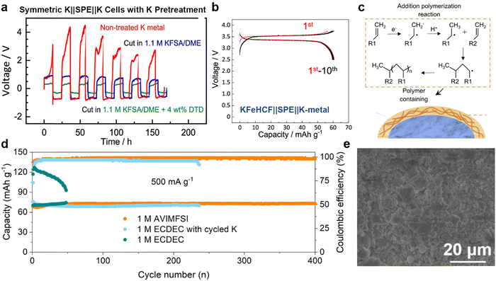 | ||
| Fig. 23 (a) K||SPE||K cells with pretreated K metal. (b) Galvanostatic charge/discharge curves of the KFeFe(CN)6 (KFeHCF)||SPE||K half-cell. Reproduced with permission from ref. 226. Copyright 2022, American Chemical Society. (c) Schematic illustration of in situ electro-polymerization-derived SEI (ISEP-SEI). (d) Cycling performance of PB||K batteries at 500 mA g−1 under different conditions. Reproduced with permission from ref. 227. Copyright 2023, Royal Society of Chemistry. (e) Top-view SEM image of KxPy@K. Reproduced with permission from ref. 228. Copyright 2021, Wiley-VCH. | ||
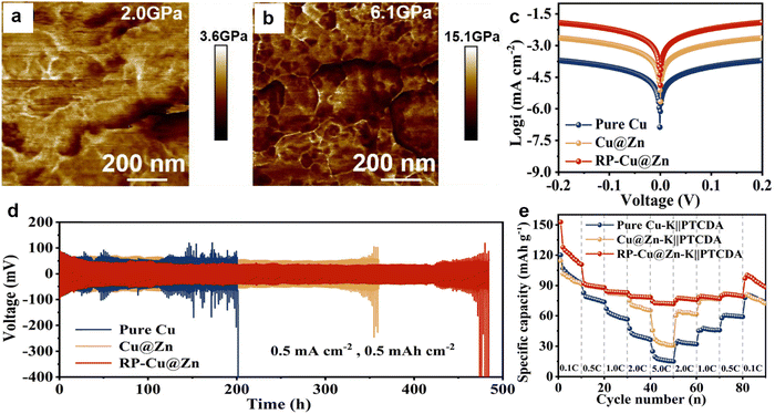 | ||
| Fig. 24 The distribution of Young's modulus on the surface of (a) bare K and (b) KxPy@K. Reproduced with permission from ref. 228. Copyright 2021, Wiley-VCH. (c) Tafel curves and (d) cycling stability of the pure Cu-K, Cu@Zn-K, and RP-Cu@Zn-K. (e) Rate performance for Pure Cu-K||PTCDA, Cu@Zn-K||PTCDA, and RP-Cu@Zn-K||PTCDA full cells. Reproduced with permission from ref. 229. Copyright 2024, Elsevier. | ||
Jiang et al.230 utilized a vanadium sulfide coating on the K surface within a temperature range of 40–60 °C to achieve a one-step in situ transformation into a heterogeneous intermediate layer composed of potassium sulfide and vanadium (K2S/V/K). Here, metallic vanadium acts as the adsorption site, while potassium sulfide accelerates the transport of potassium ions. The rate performance of K2S/V/K symmetric cells is superior to that of bare K symmetric cells (Fig. 25a). Due to the successful construction of the barrier layer, no dendrite growth phenomenon was observed on the K2S/V/K surface during 120 min of optical microscopy observation (Fig. 25b and c). Xie et al.231 obtained a potassium-philic Sn–K alloy and a pre-formed SEI layer by first wetting a thin layer of Sn-plated copper foam in ether electrolyte and then directly pressing it onto K metal (Cu@SKS; Fig. 25d). The formation of the Sn–K alloy generates electron absorption centers, greatly improving the nucleation potential of Cu@SKS compared to Cu (Fig. 25e). Sun et al.232 directly coated GeO2 on the surface of K metal, which evolved into a barrier layer rich in K–Ge alloy during the electrochemical process. The protected K symmetric battery can cycle stably for 1600 h at a current density of 0.5 mA cm−2, and the full battery composed of PTCDA also demonstrates superior rate performance (Fig. 25f and g).
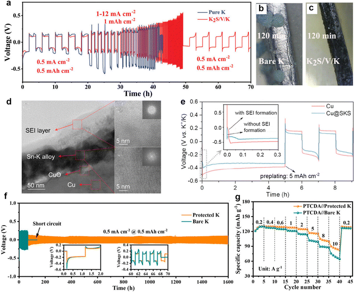 | ||
| Fig. 25 (a) Rate performance of bare K and K2S/V/K symmetric cells. In situ optical microscopy images of the K deposition process on (b) bare K and (c) K2S/V/K electrodes. Reproduced with permission from ref. 230. Copyright 2022, Wiley-VCH. (d) FIB-TEM images in relevant areas of Cu@SKS. (e) Nucleation overpotential profiles for Cu and Cu@SKS. Reproduced with permission from ref. 231. Copyright 2023, American Chemical Society. (f) Voltage–time profiles of the protected K and bare K symmetric cells at 0.5 mA cm−2 with a fixed capacity of 0.5 mA h cm−2. (g) rate performance of PTCDA||protected K and PTCDA||bare K. Reproduced with permission from ref. 232. Copyright 2023, American Chemical Society. | ||
In addition, Li et al.233 utilized BiOCl to in situ construct a dense barrier layer aggregated by particles of K3Bi and K3OCl. Compared to bare K (which failed at 178 h), the K3OCl/K3Bi@K symmetric batteries exhibit a longer stable cycle time (4000 h) and an overpotential of only 101 mV (Fig. 26a). Even at 80 C (1C = 100 mA h g−1), the full battery composed of PTCDA did not show an apparent capacity decline (Fig. 26b). Yu et al.234 proposed pressing BiVO4 onto the surface of K to spontaneously form an intermediate barrier layer composed of potassium-friendly K3VO4 and fast ion conducting K3Bi (BVO@K). Compared with bare K (0.55 V), the BVO@K symmetric cell showed a smaller voltage hysteresis of 0.18 V and greatly improved reaction kinetics in the full cells paired with PTCDA (Fig. 26c and d). Very recently, considering the internal stress issues during K deposition, our group prepared a porous carbon (PC) barrier layer with uniformly dispersed CoWO4 nanoparticles (UF-CoWO4 NPs) via a cold rolling method (Fig. 26e).235 The introduction of CoWO4 NPs not only increased the sites for potassium nucleation but also enhanced the flexibility of PC (Fig. 26f). During the process of increasing the current density from 0.5 to 10 mA cm−2, K@UF-CoWO4 NPs/PC remained stable and exhibited the lowest hysteresis voltage (Fig. 26g). The K@UF-CoWO4 NPs/PC||PTCDA full battery also corroborated the feasibility of the modified negative electrode in reducing battery polarization (Fig. 26h).
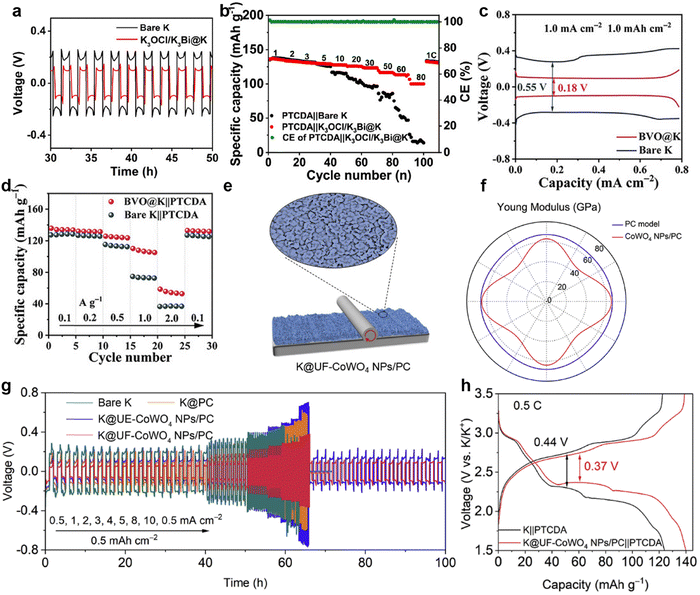 | ||
| Fig. 26 (a) Voltage–time curves of bare K and K3OCl/K3Bi@K symmetric cells at 0.5 mA cm−2/0.5 mA h cm−2. (b) Rate performance comparison. Reproduced with permission from ref. 233. Copyright 2022, American Chemical Society. (c) Plating/stripping profiles of bare K and BVO@K symmetric cells. (d) Rate capabilities of bare K||PTCDA and BVO@K||PTCDA full cells. Reproduced with permission from ref. 234. Copyright 2023, Wiley-VCH. (e) Schematic illustration of the preparation of integrated K@UF-CoWO4 NPs/PC. (f) Distributions of Young's modulus. (g) Rate properties of symmetric cells. (h) Representative charge/discharge curves of full batteries. Reproduced with permission from ref. 235. Copyright 2024, Elsevier. | ||
| Electrode | Current density (mA cm−2) | Areal capacity (mA h cm−1) | Cycle time (h) | Voltage hysteresis (mV) | Ref. |
|---|---|---|---|---|---|
| rGO@GF | 1 | 1 | 350 | 100 | 237 |
| AgLF/Whatman (NaK) | 0.4 | 0.4 | 2000 | 200 | 239 |
| GF@SnSe (K–S) | — | — | — | — | 240 |
| LiNO3@PVDF@mask | 0.4 | 0.2 | 1400 | 300 | 241 |
| HPC | 0.1 | 0.1 | 1000 | 350 | 242 |
| AlF3@PP | 0.5 | 0.5 | 2000 | 200 | 243 |
| Al2O3@PP | 0.5 | 0.5 | 2000 | 51 | 244 |
| PEP-NM | 0.5 | 0.5 | 260 | 150 | 245 |
Although Na–K alloy electrodes can be combined with carbon substrates to reduce their high surface tension, their liquid properties still draw attention to the adhesion and permeation of separators. Luo et al.239 found that an alloy cannot be formed between K and Ag (Fig. 27a). Therefore, a nano Ag-based lubrication film (AgLF) was modified on the surface of the Whatman separator to effectively prevent the infiltration of non-Newtonian fluid state Na–K alloy anode (NNFS-NaK). The SEM images illustrate that the processed separator has clearer pores and fewer surface alloy layers compared to the untreated separator (Fig. 27b). The Na–K alloy battery constructed with PB as the cathode exhibits higher specific capacity and CE at various current densities, strongly confirming the positive role of the AgLF/Whatman separator in promoting charge transfer and improving battery reversibility (Fig. 27c). More recently, Li et al.240 modified SnSe nanosheets on the cathode side of GF separator through vacuum filtration, accelerating the conversion of polysulfides and increasing the migration rate of potassium ions (Fig. 27d and e). The ultraviolet-visible (UV-Vis) spectrum shows that the solution containing SnSe corresponds to a significant decrease in the absorption band of K2S6, indicating effective adsorption of polysulfides (Fig. 27d). Thanks to the promotion of SnSe adsorption and conversion of polysulfides, the K–S battery equipped with the GF@SnSe separator furnishes 488 mA h g−1 at 0.5C (Fig. 27f), much higher than that of the battery equipped with the pristine GF separator (153 mA h g−1).
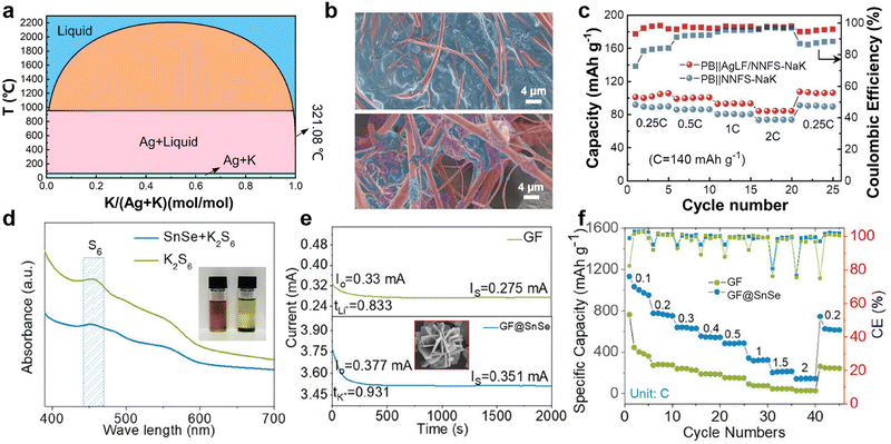 | ||
| Fig. 27 (a) Phase diagram of K–Ag. (b) SEM images of Whatman separator (top) and AgLF/Whatman separator (bottom). (c) Rate properties of full cells. Reproduced with permission from ref. 239. Copyright 2023, Elsevier. (d) The UV-Vis spectra and optical images of the K polysulfide solutions with and without SnSe. (e) Chronoamperometric curves with the GF and GF@SnSe separators based on the K–S cells. The inset shows the SEM image of SnSe nanosheets. (f) Rate performance of the K–S batteries based on the GF and GF@SnSe separators. Reproduced with permission from ref. 240. Copyright 2024, Wiley-VCH. | ||
In order to reduce the cost of separators and promote the commercialization of PMBs, new separator materials are constantly being developed. Mou et al.241 discovered that the textile materials from discarded masks, when properly treated, can be used as effective separators for PMBs, achieving the reuse of waste resources. They combined the cleaned discarded masks with an electrospun layer containing LiNO3, which can react with K dendrites, to develop a cost-effective multifunctional layer separator (Fig. 28a). Compared to batteries assembled with Whatman separators that undergo voltage fluctuations and rapid short circuits, the battery assembled with a LiNO3@poly(vinylidene fluoride)@mask (LiNO3@PVDF@mask) separator can cycle stably for 1400 cycles, and no dendrite penetration was observed on the separators after dismantling (Fig. 28b). Nanofibers, as supramolecular structures composed of multiple cellulose chains, typically have high porosity and good mechanical strength. Wang et al.242 used ramie as a raw material to develop hierarchical porous cellulose (HPC) rich in oxygen-containing functional groups as a separator for PMBs. HPC not only has high flexibility and can be freely folded, but its tensile strength is three times that of the GF separator (2.22 MPa vs. 0.85 MPa). Thanks to its excellent mechanical performance, the K symmetric battery assembled by HPC can cycle stably for 500 h without short circuits (Fig. 28c). The cyclic voltammetry (CV) curves indicate that the kinetics of the PB||K full cell equipped with HPC separator (Fig. 28d) is enhanced, and the polarization is reduced, which is attributed to the high K+ migration number of the separator.
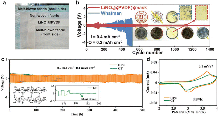 | ||
| Fig. 28 (a) Photos of the various sub-layer of the LiNO3@PVDF@mask separator. (b) Voltage profiles for symmetric cells with LiNO3@PVDF@mask and Whatman separators. Reproduced with permission from ref. 241. Copyright 2023, Wiley-VCH. (c) Voltage–time images at 0.2 mA cm−2 with a capacity of 0.4 mA h cm−2. The inset shows the supra-molecular structure of cellulose and the enlarged view of voltage–time image. (d) CV curves of PMBs with HPC and GF separators. Reproduced with permission from ref. 242. Copyright 2022, Wiley-VCH. | ||
Polyolefin separators are currently the most widely used separator materials in the market due to their excellent mechanical properties, chemical stability, and cost advantages.246,247 However, thinner polyolefin separators have the disadvantages of low surface energy, poor electrolyte wettability, and poor thermal stability. The Celgard 2400 separator is composed of two layers of polypropylene (PP) film. Liu et al.243 coated both sides of PP with AlF3 with a thickness of about 30 μm (Fig. 29a), improving the wettability between the PP separator and the electrolyte. In addition, the strong interaction between AlF3 and FSI− increased the migration number of K+ (from 0.43 to 0.76). More importantly, AlF3 reacts with K to form an artificial SEI containing KF, AlF3, and Al2O3, ensuring the long-term stable operation of K||Cu asymmetric batteries and preventing failure after 205 h, as observed in batteries assembled with PP separators (Fig. 29b). The SEM images also confirmed that the SEI on the K anode surface of the functionalized separator remained flat after 100 cycles, with no protruding K dendrites (Fig. 29c–f).
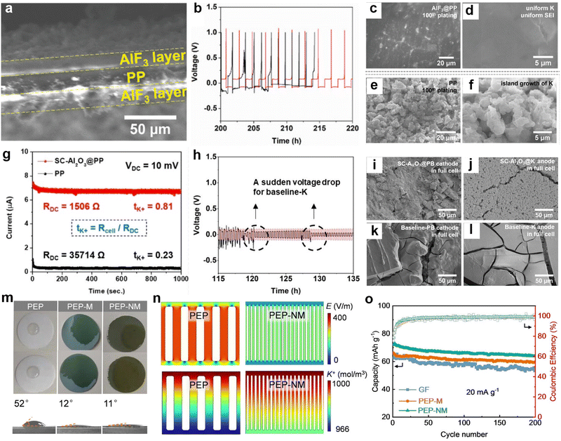 | ||
Fig. 29 (a) SEM image of the AlF3@PP trilayer cross-section. (b) Galvanostatic plating/stripping profiles for half-cells. Red: AlF3@PP. Black: PP. SEM images of anode surfaces with (c) and (d) AlF3@PP and (e) and (f) PP separators in the 100th plated condition. Reproduced with permission from ref. 243. Copyright 2022, Wiley-VCH. (g) Direct-current polarization measurements using symmetric K metal cells, with calculated transference numbers listed in the panel. (h) Galvanostatic cycling profile comparison. Red: SC-Al2O3. Black: PP. SEM images of PB cathodes and K metal anodes extracted from discharged PMB cells with (i) and (j) SC-Al2O3 and (k) and (l) PP after 100 cycles at 100 mA![[thin space (1/6-em)]](https://www.rsc.org/images/entities/char_2009.gif) g−1. Reproduced with permission from ref. 244. Copyright 2024, Wiley-VCH. (m) Photographs of electrolyte wetting process at 0 s (top) and 20 s (middle), and static KFSI electrolyte contact angles (bottom) on PEP, PEP-M, and PEP-NM separator. (n) Numerical simulation of electric field distribution (top) and K+ concentration (bottom) in cells assembled with PEP and PEP-NM separators. (o) Cycling performance of PMB full batteries with various separators. Reproduced with permission from ref. 245. Copyright 2023, Wiley-VCH. g−1. Reproduced with permission from ref. 244. Copyright 2024, Wiley-VCH. (m) Photographs of electrolyte wetting process at 0 s (top) and 20 s (middle), and static KFSI electrolyte contact angles (bottom) on PEP, PEP-M, and PEP-NM separator. (n) Numerical simulation of electric field distribution (top) and K+ concentration (bottom) in cells assembled with PEP and PEP-NM separators. (o) Cycling performance of PMB full batteries with various separators. Reproduced with permission from ref. 245. Copyright 2023, Wiley-VCH. | ||
To enhance the mechanical properties and optimize the interface compatibility between the anode and the separator, Hwang et al.248 coated Al2O3 on the surface of PP and applied it to lithium metal batteries. Subsequently, Liu et al.244 developed a PP separator modified with spin-coated Al2O3 (SC-Al2O3), similarly observing a K+ migration number as high as 0.81 (Fig. 29g). At a high current density of 3.0 mA cm−2, the SC-Al2O3@K||SC-Al2O3@K symmetric battery remained stable for 333 h, while baseline-K||baseline-K experienced significant voltage fluctuations at 120 h (Fig. 29h). Surprisingly, the modified separator simultaneously stabilized the SEI and CEI (Fig. 29i–l), as evidenced by the reduction of surface cracks on the K metal anode and PB cathode after 100 charge/discharge cycles in the SC-Al2O3@PB||SC-Al2O3@K full battery.
The Celgard 2340 separator consists of a three-layer structure of PP/polyethylene (PE)/PP (PEP), which has relatively weak interlayer adhesion and is prone to delamination failure due to dendrite growth and K deactivation during K deposition/removal. Tu et al.245 prepared –NH2-functionalized MIL-101(Cr) using the blade coating method to modify the PEP separator (PEP-NM). The rich porosity of NM allows PEP-NM separators to exhibit superior wettability compared to MIL-101(Cr)-coated PEP (PEP-M) and original PEP separators (Fig. 29m). While enhancing the mechanical properties of the separator, the presence of functional groups guides a uniform flux of ions, resulting in a more uniform distribution of internal electric field and K+ concentration in batteries with PEP-NM (Fig. 29n). Compared to commercial GF separators with initial capacity of 67.0 mA h g−1, PMBs with PEP-NM separators exhibit higher initial reversible capacity (72.6 mA h g−1) and capacity retention (Fig. 29o).
3.3. Electrolyte engineering
The electrolyte, as a key component in the battery, primarily functions as a medium for ion transport.249,250 During the first charge and discharge of the battery, the electrolyte forms a passivation layer on the electrode surface, preventing further side reactions between the electrode material and the electrolyte.121,251 In PMBs, a reasonable selection of electrolyte salts, solvents, and additives can stabilize the interface between the K metal anode and the electrolyte and suppress dendrite growth. The introduction of special additives, such as flame retardants, can enhance the safety of the batteries to some extent.3.3.1.1. Salt selection. The selection of electrolyte salts is crucial for the kinetics and cycling stability of potassium-ion batteries. Potassium hexafluorophosphate (KPF6) and KFSI are considered the main electrolyte salts due to their appropriate solubility in ester and ether solvents.252,253 In 2017, Xiao et al.254 first evaluated the deposition/stripping process of K metal anodes in four different electrolytes: 1 M KFSI-DME, 1 M KPF6-DME, 1 M potassium bis(trifluoromethanesulfonyl)imide (KTFSI)-DME, and 0.8 M KPF6-EC/DEC. The results showed that KFSI-DME is the only electrolyte capable of long-term and highly reversible deposition/stripping at room temperature, and can achieve an electrochemical window of up to 5 V at high concentrations. When studying the K–Na alloy (KNA) anode, Tai et al.255 found that when the Na content in the alloy was 3.5 wt%, its fluidity decreased compared to the most commonly studied liquid K–Na alloy (K
![[thin space (1/6-em)]](https://www.rsc.org/images/entities/char_2009.gif) :
:![[thin space (1/6-em)]](https://www.rsc.org/images/entities/char_2009.gif) Na = 66.3
Na = 66.3![[thin space (1/6-em)]](https://www.rsc.org/images/entities/char_2009.gif) :
:![[thin space (1/6-em)]](https://www.rsc.org/images/entities/char_2009.gif) 33.7, w/w), making it easier to process into sheet-like electrodes. They conducted in-depth research on the deposition process of KNA and metal K on Cu in a 0.8 M KPF6–NaPF6 (K
33.7, w/w), making it easier to process into sheet-like electrodes. They conducted in-depth research on the deposition process of KNA and metal K on Cu in a 0.8 M KPF6–NaPF6 (K![[thin space (1/6-em)]](https://www.rsc.org/images/entities/char_2009.gif) :
:![[thin space (1/6-em)]](https://www.rsc.org/images/entities/char_2009.gif) Na = 16.2
Na = 16.2![[thin space (1/6-em)]](https://www.rsc.org/images/entities/char_2009.gif) :
:![[thin space (1/6-em)]](https://www.rsc.org/images/entities/char_2009.gif) 1, m/m)-DME electrolyte, observing the CE of the battery and the morphological changes on the Cu surface (Fig. 30a and b). The results showed that in the mixed electrolyte containing NaPF6, the CE of KNA-3.5||Cu battery improved more rapidly, and the KNa2 metastable phase appeared during plating, which promoted the nucleation process of K and Na, effectively avoiding the formation of dendritic structures commonly seen on the electrode surface of K||Cu batteries.
1, m/m)-DME electrolyte, observing the CE of the battery and the morphological changes on the Cu surface (Fig. 30a and b). The results showed that in the mixed electrolyte containing NaPF6, the CE of KNA-3.5||Cu battery improved more rapidly, and the KNa2 metastable phase appeared during plating, which promoted the nucleation process of K and Na, effectively avoiding the formation of dendritic structures commonly seen on the electrode surface of K||Cu batteries.
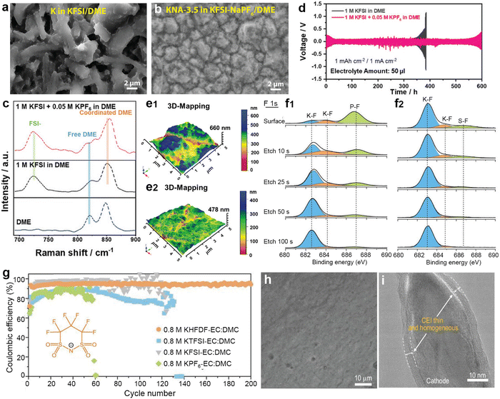 | ||
| Fig. 30 The surface morphology of the Cu counter electrode of the bare K||Cu cell in (a) KFSI/DME electrolyte and the KNA-3.5||Cu cell in (b) KFSI-NaPF6/DME mixed electrolyte after cycling. Reproduced with permission from ref. 255. Copyright 2021, Wiley-VCH. (c) Raman spectra of DME solvent and electrolyte solutions with/without 0.05 M KPF6 in the baseline electrolyte. (d) Galvanostatic cycling test of K||K symmetric cells with/without 0.05 M KPF6 in the baseline electrolyte. 3D AFM topographic images of K electrodeposited on the Cu substrate at 4 mA cm−2/1 mA h cm−2 in (e1) baseline electrolyte and (e2) 0.05 M KPF6-containing electrolyte. Reproduced with permission from ref. 256. Copyright 2023, Wiley-VCH. XPS depth profiles for the F 1s spectra of K||Cu cells with (f1) KPF6-based and (f2) KHFDF-based electrolytes. (g) Cycling test of K metal in K||Cu half-cells with different electrolytes. The inset shows the molecular structure of the HFDF− anion. (h) SEM image of the Al foil in the KHFDF-based electrolyte. (i) TEM image of the CEI on the cathode surface with the KHFDF-based electrolyte. Reproduced with permission from ref. 257. Copyright 2022, National Science Review. | ||
Based on the difference in solvation energy between KPF6-DME and KFSI-DME (−0.49 eV and −0.53 eV, respectively), Park et al.256 added 0.05 M KPF6 to 1 M KFSI-DME to alter the solvation structure of K+. In a double salt electrolyte containing a small amount of KPF6, solvent decomposition is reduced due to the increased proportion of coordinated DME (Fig. 30c). The mechanical strength of the SEI layer is enhanced, allowing K||K symmetric batteries to cycle for 600 h even with a small amount of double salt electrolyte (50 μL; Fig. 30d). The 3D AFM image demonstrates that the surface of K deposited in the double salt electrolyte is relatively flat, while the height of K deposited in the electrolyte without KPF6 changes significantly (Fig. 30e).
It is worth noting that although the SEI layer formed by the conventional KFSI salt is stable, it is not suitable for high-voltage battery systems, and the cost of high-concentration KFSI electrolytes is high. Hu et al.257 proposed an innovative approach: replacing –F group in FSI− with –CF3 groups to obtain F-rich interfaces, and using cyclic molecules, which have lower LUMO energy levels compared to linear molecules, to more easily passivate the anode. Based on this idea, they used cyclic perfluoroalkyl sulfonyl imide anion (HFDF−). XPS analysis reveals that the KF component in the SEI layer formed by anion decomposition in the KHFDF electrolyte is significantly higher than that in KPF6-based electrolyte (Fig. 30f). The K||Cu battery based on the KHFDF electrolyte maintains a stable CE of up to 200 cycles (average CE of 94.3%; Fig. 30g). In addition, the KHFDF-based electrolyte does not decompose at voltages up to 4.7 V and the Al surface is smooth, whereas mild corrosion is observed on the Al surface using the KPF6-based electrolyte (Fig. 30h). In the layered metal oxide||K battery, the CEI formed on the surface of the layered oxide using the KHFDF-based electrolyte is more uniform than that formed using the KPF6-based electrolyte (Fig. 30i).
3.3.1.2. Solvent selection. In the pursuit of high-performance electrolytes, incorporating inert cosolvents such as low-polarity fluorinated ethers into high concentration electrolytes is considered as an effective strategy to reduce electrolyte viscosity and enhance ion conductivity.258 These localized high-concentration electrolytes (LHCEs) benefit from unique solvation structure that can promote the preferential reduction of anions.259 Compared to traditional low concentration electrolytes (LCE), they are more conducive to forming a stable SEI layer on the electrode surface. Researchers have conducted in-depth studies on the optimal amount of TTE diluent in KFSI-DME electrolyte. By comparing the ion conductivities of LHCE1 (KFSI/DME/TTE = 1
![[thin space (1/6-em)]](https://www.rsc.org/images/entities/char_2009.gif) :
:![[thin space (1/6-em)]](https://www.rsc.org/images/entities/char_2009.gif) 2
2![[thin space (1/6-em)]](https://www.rsc.org/images/entities/char_2009.gif) :
:![[thin space (1/6-em)]](https://www.rsc.org/images/entities/char_2009.gif) 0.5), LHCE2 (KFSI/DME/TTE = 1
0.5), LHCE2 (KFSI/DME/TTE = 1![[thin space (1/6-em)]](https://www.rsc.org/images/entities/char_2009.gif) :
:![[thin space (1/6-em)]](https://www.rsc.org/images/entities/char_2009.gif) 2
2![[thin space (1/6-em)]](https://www.rsc.org/images/entities/char_2009.gif) :
:![[thin space (1/6-em)]](https://www.rsc.org/images/entities/char_2009.gif) 1), and LHCE3 (KFSI/DME/TTE = 1
1), and LHCE3 (KFSI/DME/TTE = 1![[thin space (1/6-em)]](https://www.rsc.org/images/entities/char_2009.gif) :
:![[thin space (1/6-em)]](https://www.rsc.org/images/entities/char_2009.gif) 2
2![[thin space (1/6-em)]](https://www.rsc.org/images/entities/char_2009.gif) :
:![[thin space (1/6-em)]](https://www.rsc.org/images/entities/char_2009.gif) 1.5), it was found that LHCE2 exhibited the highest conductivity (Fig. 31a).260 The K||Cu battery using LHCE2 can still maintain a high CE of 98.1% after 800 cycles (Fig. 31b). In addition, the charge/discharge curve of the K||KFeHCF cell at the 100th cycle closely matches that at the 10th cycle, verifying its excellent reversibility (Fig. 31c).
1.5), it was found that LHCE2 exhibited the highest conductivity (Fig. 31a).260 The K||Cu battery using LHCE2 can still maintain a high CE of 98.1% after 800 cycles (Fig. 31b). In addition, the charge/discharge curve of the K||KFeHCF cell at the 100th cycle closely matches that at the 10th cycle, verifying its excellent reversibility (Fig. 31c).
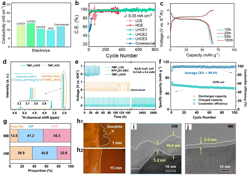 | ||
| Fig. 31 (a) Ionic conductivity of different electrolytes. (b) Comparison of K plating/stripping on the Cu electrode in different electrolytes at 0.05 mA cm−2 with an areal capacity of 0.05 mA h cm−2. (c) Charge/discharge voltage profiles at different cycles of the K||KFeHCF cell. Reproduced with permission from ref. 260. Copyright 2023, American Chemical Society. (d) 1H NMR spectra of the –CH3 for the TMP solvent in electrolytes with and without TFTFE. (e) Galvanostatic plating/stripping profiles for K||Al half-cells with various electrolytes. (f) K||PB full cells with TMP_LHCE. Reproduced with permission from ref. 261. Copyright 2023, Elsevier. (g) Ratio of various coordination structures in DM and MB corresponding to Raman spectra. In situ optical microscopy of deposited K in K||K symmetric cells in (h1) DM and (h2) MB. TEM images of cycled KMO electrode in (i) DM and (j) MB. Reproduced with permission from ref. 262. Copyright 2024, Wiley-VCH. | ||
Chen et al.261 chose to use low-polarity 1,1,2,2-tetrafluoroethyl-2,2-trifluoroethyl ether (TFTFE) as a diluent for non-flammable KFSI/TMP electrolytes (KFSI![[thin space (1/6-em)]](https://www.rsc.org/images/entities/char_2009.gif) :
:![[thin space (1/6-em)]](https://www.rsc.org/images/entities/char_2009.gif) TMP
TMP![[thin space (1/6-em)]](https://www.rsc.org/images/entities/char_2009.gif) :
:![[thin space (1/6-em)]](https://www.rsc.org/images/entities/char_2009.gif) TFTFE = 1
TFTFE = 1![[thin space (1/6-em)]](https://www.rsc.org/images/entities/char_2009.gif) :
:![[thin space (1/6-em)]](https://www.rsc.org/images/entities/char_2009.gif) 1.7
1.7![[thin space (1/6-em)]](https://www.rsc.org/images/entities/char_2009.gif) :
:![[thin space (1/6-em)]](https://www.rsc.org/images/entities/char_2009.gif) 2). As evidenced by 1H NMR, the addition of the diluent causes the non-solvated TFTFE to squeeze FSI− into the internal solvation layer, resulting in stronger anion–cation interactions and larger chemical shifts (Fig. 31d). The obtained LHCE effectively alleviates the corrosion of FSI− on the Al current collector, enabling the K||Al battery to cycle for 3450 h without failure (Fig. 31e). The K||PB battery shows a capacity of 55 mA h g−1 at 50 mA g−1, demonstrating good compatibility between the electrolyte and the cathode material (Fig. 31f). Gu et al.262 developed a novel electrolyte (MB) by adding ethylene glycol dibutyl ether (DBE) cosolvent to 1.5 M KFSI-dipropylene glycol dimethyl ether (DPGDME, abbreviated as DM). This significantly elevated the oxidation potential from 4.22 to 4.94 V. By calculating the peak area ratios of free FSI−, contact ion pairs (CIP, anions coordinated with a single K+), and aggregates (AGG, anions coordinated with multiple K+) in Raman spectroscopy, the proportion of free FSI− in MB (13.5%) was lower than that in DM (36.9%) (Fig. 31g). This proves that the introduction of DBE promotes the enrichment of FSI− towards the internal solvation sheaths of K+, which is beneficial for constructing an inorganic-rich interfacial layer. Therefore, dendrites can be observed on the K surface of K||K batteries in DM for 1 min, while no dendrites were observed in MB for 15 min (Fig. 31h). TEM observations of the CEI layer of K0.67MnO2 (KMO) positive electrode material showed that the CEI formed in MB is thin and uniform (Fig. 31i and j).
2). As evidenced by 1H NMR, the addition of the diluent causes the non-solvated TFTFE to squeeze FSI− into the internal solvation layer, resulting in stronger anion–cation interactions and larger chemical shifts (Fig. 31d). The obtained LHCE effectively alleviates the corrosion of FSI− on the Al current collector, enabling the K||Al battery to cycle for 3450 h without failure (Fig. 31e). The K||PB battery shows a capacity of 55 mA h g−1 at 50 mA g−1, demonstrating good compatibility between the electrolyte and the cathode material (Fig. 31f). Gu et al.262 developed a novel electrolyte (MB) by adding ethylene glycol dibutyl ether (DBE) cosolvent to 1.5 M KFSI-dipropylene glycol dimethyl ether (DPGDME, abbreviated as DM). This significantly elevated the oxidation potential from 4.22 to 4.94 V. By calculating the peak area ratios of free FSI−, contact ion pairs (CIP, anions coordinated with a single K+), and aggregates (AGG, anions coordinated with multiple K+) in Raman spectroscopy, the proportion of free FSI− in MB (13.5%) was lower than that in DM (36.9%) (Fig. 31g). This proves that the introduction of DBE promotes the enrichment of FSI− towards the internal solvation sheaths of K+, which is beneficial for constructing an inorganic-rich interfacial layer. Therefore, dendrites can be observed on the K surface of K||K batteries in DM for 1 min, while no dendrites were observed in MB for 15 min (Fig. 31h). TEM observations of the CEI layer of K0.67MnO2 (KMO) positive electrode material showed that the CEI formed in MB is thin and uniform (Fig. 31i and j).
The aforementioned strategies for high-voltage batteries or preventing ion-solvent co-intercalation in graphite anodes mainly focus on solvent modification by adding fluorinated molecule cosolvents.263 Nevertheless, these electrolytes are quite costly. Therefore, new low-cost ether solvents with weak solvation are continuously being developed to achieve stable cycling of PMBs. Our group incorporated 1,1,2,2-tetrafluoroethyl-2,2,3,3-tetrafluoropropyl ether, 1H,1H,5H-perfluoropentyl-1,1,2,2-tetrafluoroethylether, and fluoromethyl-1,1,1,3,3,3-hexafluoroisopropyl ether, which exhibit high compatibility with potassium metal, as diluents into common trimethyl phosphate (TMP) and TEP to formulate a moderately weakly solvated high-entropy local high-concentration electrolyte (HELHCE).264 Upon the addition of the diluents, multiple dispersed high-concentration clusters were formed within the HELHCE, resulting in faster diffusion of K+ in HELHCE compared to LHCE and high-concentration electrolytes (HCE) (Fig. 32a). Due to the introduction of high-entropy solvents, the average deposition/stripping efficiency of this electrolyte in K||Cu batteries reached 99.4% (Fig. 32b). Furthermore, the low-temperature performance of the electrolyte was significantly enhanced. Potassium metal batteries with PTCDA as the cathode maintained specific capacities of 94.0 and 77.3 mA h g−1 at −20 °C and −40 °C, respectively (Fig. 32c). Yu et al.265 replaced the methoxy group at the end of diethylene glycol dimethyl ether (G2) with a butoxy group to obtain diethylene glycol dibutyl ether (DiDBE) as a new solvent, in order to reduce solvation of K+ (Fig. 32d). However, its long-chain structure increases the electrolyte viscosity, necessitating the addition of DTD as a diluent to improve ionic conductivity. The results showed that in the resultant DiDBE-D electrolyte, the K2MnFe(CN)6·xH2O (MnHCF)||K battery achieved an initial CE of up to 90.9%, which was superior to the 72.4% in the carbonate electrolyte, and no failure occurred after 200 cycles (Fig. 32e).
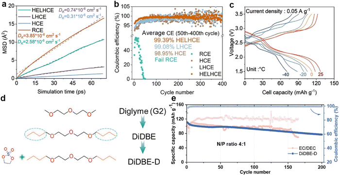 | ||
| Fig. 32 (a) K+ diffusion coefficients of HELHCE, LHCE, HCE, and regular-concentration electrolytes (RCE) from the mean square displacement statistics of potassium ions over the last 50 ps of molecular dynamics simulation. (b) Cycling measurements of the CE of K metal on Cu collector in K||Cu cells using HELHCE, LHCE, HCE, and RCE. (c) Charge/discharge profiles of PTCDA||K cells using HELHCE at various temperatures. Reproduced with permission from ref. 264. Copyright 2025, Wiley-VCH. (d) Rational design of ethers with high anodic stability and kinetics. (e) Cycling performance of the MnHCF||K cell in diverse electrolytes. Reproduced with permission from ref. 265. Copyright 2024, Wiley-VCH. | ||
Wang et al.266 designed a weakly solvated electrolyte (E@1,3-DX) in which KFSI was dissolved in the cyclic ether 1,3-dioxane (1,3-DX). Raman spectra confirmed that E@1,3-DX is dominated by CIP and AGG, whereas E@EC/DEC is dominated by solvent-separated ion pairs (SSIP), indicating that the solvation structure of E@1,3-DX is anion-centered (Fig. 33a). Due to the formation of a KF-rich SEI with less solvent decomposition, the K||carbon coated Al (Al–C) battery achieves a high average CE of 99.20% in E@1,3-DX (Fig. 33b and c). The PMB composed of K||KxMn[Fe(CN)6]·yH2O in E@1,3-DX exhibited high voltage stability and extremely low polarization, which is rare in conventional ether-based electrolytes (Fig. 36d). Besides, Jeon et al.267 developed a non-flammable potassium salt concentrated ionic liquid electrolyte (PCIL) composed of KFSI and 1-methyl-1-propylpyrrolidinium bis(fluorosulfonyl)imide (Pyr13FSI) to address battery safety concerns (Fig. 33e). Due to the formation of SEI containing K+ ion conductors such as K2SO4 and K2SO3 on the Cu surface, K||Cu batteries exhibited a higher exchange current density in PCIL (30.5 μA cm−2vs. 2.5 μA cm−2 in EC/PC) (Fig. 33f).
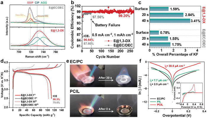 | ||
| Fig. 33 (a) Raman spectra of E@1,3-DX and the E@EC/DEC, deconvoluted for different components in the solvation structures. (b) CEs of K||Al-C cells in the two electrolytes. (c) Percentages of KF in overall SEI at varied depths in the two electrolyte systems. (d) Charging/discharging curves for the 1st and the 50th cycles of the full cells under 150 mA g−1. Reproduced with permission from ref. 266. Copyright 2024, Wiley-VCH. (e) Flammability test of EC/PC and PCIL. (f) Tafel plots of the K||Cu cells. The inset shows the concerned CV curves. Reproduced with permission from ref. 267. Copyright 2024, Elsevier. | ||
The optimization of liquid electrolytes is committed to developing new solvents and cosolvents to optimize the solvent structure, improve the performance of HCEs, enhance their ionic conductivity, promote the preferential reduction of anions, and form stable CEI and SEI layers.268 However, cost remains one of the key factors restricting the widespread application of these high-performance electrolytes.
3.3.1.3. Additive selection. Electrolyte additives typically optimize the inorganic composition of the SEI by promoting the participation of anions in the construction of SEI or affecting the decomposition of solvent molecules to participate in the construction of SEI. As an electrolyte additive for lithium metal batteries, the reduction of NO3− in LiNO3 can alter the inorganic composition of the SEI layer on lithium metal, resulting in denser lithium deposition.269–271
For PMBs, Wang et al.272 first reported the application of KNO3 as an electrolyte additive for KFSI-DME in 2021. This additive can form an SEI rich in N/F with high potassium ion conductivity, which is significant for improving the ion conductivity efficiency of PMBs. Han et al.273 first proposed the introduction of 0.1 wt% NaNO3 as an additive in 0.8 KPF6-EC/DEC electrolyte, which not only helps to enhance the mechanical stability of the SEI layer but also forms Na–K liquid alloy with K to alleviate SEI stress (Fig. 34a). The Tafel curve shows that the electrolyte with added NaNO3 has a higher corrosion potential than the blank electrolyte (BE), which validates that the dense passivation layer effectively prevents the electrolyte from decomposing again (Fig. 34b). In the K||K symmetric battery test, the electrolyte containing NaNO3 additive shows a slight increase in overpotential with the increase of current density, but the overall performance is significantly better than the BE control group (Fig. 34c). Due to the low dissociation energy of NaNO3 in EC/DEC, Park et al.274 successfully achieved the addition of 0.02 M NaNO3 to 0.5 M KPF6-EC/DEC (denoted as D-2NE) by introducing dimethylacetamide (DMA) into BE. After cycling with D-2NE in a full battery equipped with a FeHCF cathode, the K metal anode and separator surface show a smooth state, leading to a stable cycling performance with a reversible capacity of 60 mA h g−1 (Fig. 34d and e).
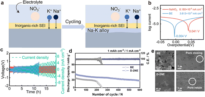 | ||
| Fig. 34 (a) Schematic diagram of enhanced interface formation. (b) Tafel curves of K||K symmetric cells. (c) Rate current density test of K||K symmetric cells. Reproduced with permission from ref. 273. Copyright 2023, Elsevier. (d) Cycling performance of the full-cells in different electrolytes. (e) SEM images of cycled K–metal anodes and separators (polymer membrane) from K||FeHCF full cells. Reproduced with permission from ref. 274. Copyright 2024, Elsevier. | ||
In SEI design, mechanical properties such as Young's modulus and elastic strain limit are highly valued. An elastic SEI can cope with the volume expansion of K metal during deposition, thereby significantly improving cycling performance of the battery. Zhang et al.275 added 0.07 wt% of polymer pigment Green 7 (PG-7) to the carbonate electrolyte to form a mesh-like elastic SEI layer that uniformly covers the K surface. NMR spectral analysis shows that the chemical shift in the electrolyte containing PG-7 decreases (Fig. 35a), indicating that the additive affects the solvation structure between K+ and solvent molecules. Stress curves tested on graphite electrodes cycled in electrolytes containing PG-7 show higher coincidence between the “approach” and “withdraw” curves, implying superior SEI elasticity (Fig. 35b and c). Consequently, the K||K symmetric battery can stably cycle in the optimized electrolyte for 1400 h without any short circuits (Fig. 35d). Note that the overpotential in the voltage curve shows a trend of initial decrease followed by an increase. This change may be attributed to activation during cycling and the subsequent thickening of the SEI caused by uneven potassium deposition, dendrite growth, and the formation of inactive potassium.167,197 Tang et al.216 added 2 vol% polydimethylsiloxane (PDMS) to a 0.4 M KPF6-DME electrolyte and conducted cycling tests on K||Cu batteries at −40 °C (Fig. 35e). The results showed that after 100 cycles, the CE of the battery remained at 99.1%. The time-of-flight secondary ion mass spectrometry (TOF-SIMS) mapping reveals that the formation of KO–Si chemical bonds between PMDS and K, as well as the in situ formation of electron-rich protective layers that inhibit the sustained decomposition of DME on the K surface (Fig. 35f). Inspired by this, they constructed anode-free Cu||KPTCDA (potassium-intercalated PTCDA) pouch cells, which achieved a capacity retention rate of 90% after 20 cycles (Fig. 35g).
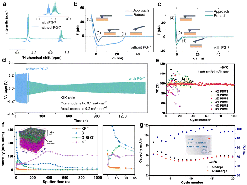 | ||
Fig. 35 (a) 1H NMR spectroscopy of the tested electrolytes. AFM-based nanoindentation tests of graphite electrodes after five cycles in the test electrolytes (b) without PG-7 and (c) with PG-7. (d) Comparison of the performance of K||K symmetric cells in the presence and absence of PG-7. Reproduced with permission from ref. 275. Copyright 2024, Wiley-VCH. (e) K plating/stripping CE of K||Cu half-cells with various electrolytes at −40![[thin space (1/6-em)]](https://www.rsc.org/images/entities/char_2009.gif) °C. (f) Depth profile curves of TOF-SIMS in negative mode. The inset shows the 3D distribution overlay. (g) Cycling performance at 10 mA g−1. The inset shows the photograph of a pouch cell. Reproduced with permission from ref. 216. Copyright 2023, Springer Nature. °C. (f) Depth profile curves of TOF-SIMS in negative mode. The inset shows the 3D distribution overlay. (g) Cycling performance at 10 mA g−1. The inset shows the photograph of a pouch cell. Reproduced with permission from ref. 216. Copyright 2023, Springer Nature. | ||
While most additive research focuses on the stability of the SEI, the development of functional additives to inhibit K dendrite growth and protect the CEI layer is also of practical significance. For example, Jiang et al.276 introduced a pentyltriphenylphosphonium bromide (ATPPB) additive with a low reduction potential and ease of decomposition into 0.8 M KPF6-EC/DEC (ED) electrolyte (the optimized electrolyte is called AED) (Fig. 36a). The pentyltriphenylphosphonium cation of ATPPB can form a cationic shielding layer on the surface of the crystal nucleus, effectively alleviating island-like deposition on the K surface (Fig. 36b). On the other hand, ATPPB reacts with K to generate KxPy fast-ion conductors, promoting K+ transport, which reduces the nucleation potential of K||Cu using AED electrolyte from 89.4 mV to 53.8 mV (Fig. 36c). Afterwards, Park et al.277 added 1 wt% adiponitrile (ADN, optimized electrolyte: e-ADN) to 0.5 M KPF6-EC/DEC (e-control) to improve the stability of K metal anodes and layered oxides. The nucleation overpotential of K||Cu batteries in e-ADN is twice lower than that in e-control, mainly attributed to the high electronegativity of the nitrile group in ADN, which can promote the dissociation of KPF6 (Fig. 36d and e). In the PMBs assembled with layered O3-Na0.9Ca0.035Cr0.97Ti0.03O2 (O3-NCCTO) as the positive electrode material, the battery using e-ADN can cycle for 200 cycles at a current density of 4 mA cm−2, while the battery using e-control quickly fails. Differential scanning calorimetry (DSC) analysis of the cathode in the fully charged state after the 10th cycle (Fig. 36f) shows that the cathode cycled in e-ADN exhibits a higher peak temperature but lower heat generation, indicating a more stable CEI layer.
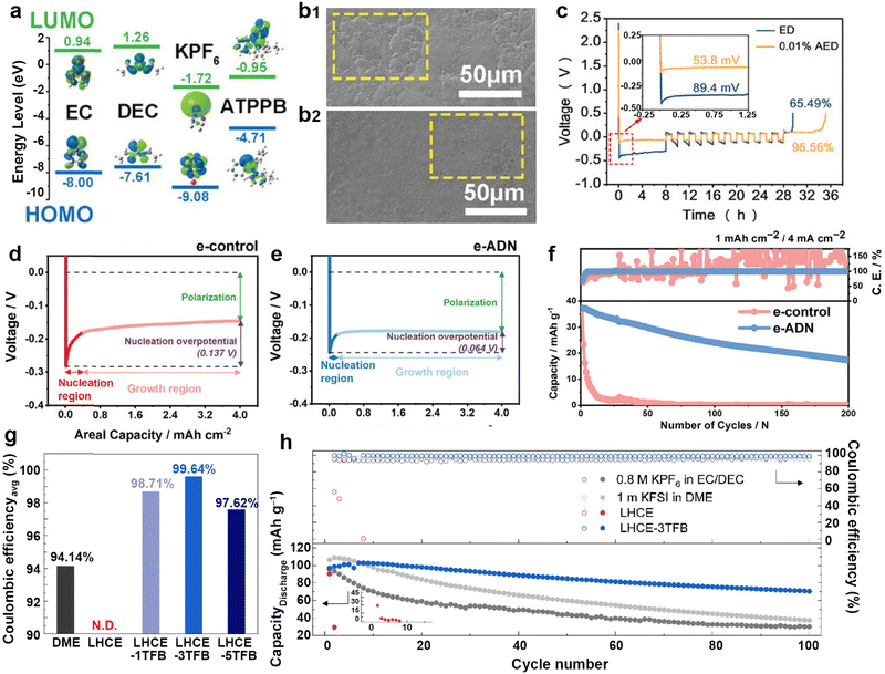 | ||
| Fig. 36 (a) Molecular orbital energies of solvents calculated by DFT. SEM images of plated K in (b1) ED and (b2) ED with 0.01% AED after 10 cycles at 0.5 mA cm−2 with a capacity of 0.5 mA h cm−2. (c) CE measured in blank and experimental electrolytes using Aurbach's method. Reproduced with permission from ref. 276. Copyright 2023, Wiley-VCH. Nucleation potential images of the electrodeposited K in (d) e-control and (e) e-ADN. (f) Cycling performance of full cells in different electrolytes. Reproduced with permission from ref. 277. Copyright 2023, Wiley-VCH. (g) The calculated average CE of electrolytes from voltage profiles of the modified Aurbach method. N.D. indicates not measurable. (h) Discharge capacity and CE over 100 cycles. Reproduced with permission from ref. 278. Copyright 2023, Wiley-VCH. | ||
Although high concentration ether-based electrolytes are favorable for forming dense SEI layers due to their solvation structure rich in metal cations, their viscous liquid form results in poor wettability.279 TTE is a common diluent that helps to form LHCEs. TTE can also increase the oxidation potential of the electrolyte without changing the solvation structure of the high concentration electrolyte. Recently, Lee et al.278 introduced 1,3,5-trifluorobenzene (TFB) as an additive to suppress the potassiation reaction in LHCEs. The K||Cu battery demonstrates the highest average CE in LHCE-3TFB (where TFB accounts for 3 wt% in TTE), indicating that TFB has good compatibility with K metal (Fig. 36g). Furthermore, the K||K0.5MnO2 battery exhibits the highest capacity retention rate after 100 cycles in LHCE-3TFB, confirming that TFB effectively prevents the K− reaction of K metal in LHCE and participates in forming a more stable CEI (Fig. 36h). In summary, electrolyte additives play a crucial role in the SEI and CEI design of PMBs. By reasonably selecting and optimizing the types and concentrations of additives, the performance of PMBs can be greatly improved.
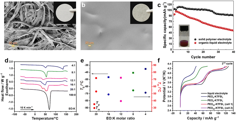 | ||
Fig. 37 SEM images of (a) cellulose nonwoven membrane and (b) PPCB-SPE. The inset is the digital image. (c) Cycling performance of PTCDA in PPCB-SPE or organic-liquid electrolyte at 20 mA g−1. The inset shows the digital image of the solubility test for PTCDA in 1M KFSI in EC/DEC (v/v, 1![[thin space (1/6-em)]](https://www.rsc.org/images/entities/char_2009.gif) : :![[thin space (1/6-em)]](https://www.rsc.org/images/entities/char_2009.gif) 1) electrolyte. Reproduced with permission from ref. 281. Copyright 2018, Elsevier. (d) DSC scans of PEO-KTFSI blends with different EO:K molar ratios and pure PEO. (e) Dependence of glass transition temperature (Tg) and melting temperature (Tm) values on the EO 1) electrolyte. Reproduced with permission from ref. 281. Copyright 2018, Elsevier. (d) DSC scans of PEO-KTFSI blends with different EO:K molar ratios and pure PEO. (e) Dependence of glass transition temperature (Tg) and melting temperature (Tm) values on the EO![[thin space (1/6-em)]](https://www.rsc.org/images/entities/char_2009.gif) : :![[thin space (1/6-em)]](https://www.rsc.org/images/entities/char_2009.gif) K molar ratio in PEO-KTFSI blends. (f) Galvanostatic charge profiles in the second cycle. Reproduced with permission from ref. 282. Copyright 2022, American Chemical Society. K molar ratio in PEO-KTFSI blends. (f) Galvanostatic charge profiles in the second cycle. Reproduced with permission from ref. 282. Copyright 2022, American Chemical Society. | ||
Polyethylene oxide (PEO) has been widely studied in lithium-ion batteries due to its excellent heat resistance and ability to dissolve electrolyte salts.283–286 However, because of the low dissociation energy of potassium salts, PEO finds it challenging to combine with them to generate highly conductive potassium-based SPEs. Khudyshkina et al.282 first investigated the formulation of PEO with the electrolyte salt KTFSI. When the molar ratio of PEO to KTFSI is 12![[thin space (1/6-em)]](https://www.rsc.org/images/entities/char_2009.gif) :
:![[thin space (1/6-em)]](https://www.rsc.org/images/entities/char_2009.gif) 1, the mixture exhibits the lowest melting point and crystallinity (Fig. 37d and e), and the movement of its amorphous segment may favour ion transport. Unfortunately, it cannot be processed into a self-supporting separator. By comparing the charging curves of K||K2Fe[Fe(CN)6] batteries assembled with processable blends at ratios of 4
1, the mixture exhibits the lowest melting point and crystallinity (Fig. 37d and e), and the movement of its amorphous segment may favour ion transport. Unfortunately, it cannot be processed into a self-supporting separator. By comparing the charging curves of K||K2Fe[Fe(CN)6] batteries assembled with processable blends at ratios of 4![[thin space (1/6-em)]](https://www.rsc.org/images/entities/char_2009.gif) :
:![[thin space (1/6-em)]](https://www.rsc.org/images/entities/char_2009.gif) 1, 8
1, 8![[thin space (1/6-em)]](https://www.rsc.org/images/entities/char_2009.gif) :
:![[thin space (1/6-em)]](https://www.rsc.org/images/entities/char_2009.gif) 1, and 20
1, and 20![[thin space (1/6-em)]](https://www.rsc.org/images/entities/char_2009.gif) :
:![[thin space (1/6-em)]](https://www.rsc.org/images/entities/char_2009.gif) 1, they found that only under the PEO20-KTFSI1 condition can the battery capacity be similar to that in liquid electrolytes (Fig. 37f). It is worth mentioning that due to the close proximity of adjacent chains, crystalline PEO severely limits the migration of K+. To overcome the limitations of PEO, Lyu et al.287 ingeniously designed potassium bismuth iodide (K4BiI7) as a filler for PEO and constructed an iodinated solid polymer electrolyte (ISPE) to activate K+ channels in PEO chains. This functional filler can dissociate I3− to oxidize dendritic K in situ, thereby inhibiting interfacial dendrites. Meanwhile, Bi3+ can produce a K–Bi alloy interlayer with K, further promoting ion conduction.
1, they found that only under the PEO20-KTFSI1 condition can the battery capacity be similar to that in liquid electrolytes (Fig. 37f). It is worth mentioning that due to the close proximity of adjacent chains, crystalline PEO severely limits the migration of K+. To overcome the limitations of PEO, Lyu et al.287 ingeniously designed potassium bismuth iodide (K4BiI7) as a filler for PEO and constructed an iodinated solid polymer electrolyte (ISPE) to activate K+ channels in PEO chains. This functional filler can dissociate I3− to oxidize dendritic K in situ, thereby inhibiting interfacial dendrites. Meanwhile, Bi3+ can produce a K–Bi alloy interlayer with K, further promoting ion conduction.
As shown in the Arrhenius diagram, when the K4BiI7 content reaches 10%, the ISPE exhibits the highest ionic conductivity (3.25 × 10⁻⁴ S cm−1 at 50 °C) (Fig. 38a). When using PEO-KFSI, the K||K symmetric battery exhibited significant voltage oscillation and signs of short circuit after 10 h (Fig. 38b). X-ray computed tomography (CT) studies also confirmed dendrite growth penetrating the PEO-KFSI electrolyte. In contrast, the symmetric battery with K4BiI7 filler initially observed slight voltage oscillations (Fig. 38c), but due to interface stabilization, it recovered stable operation after 40 h. Furthermore, the PB||K battery with ISPE exhibits stable charge/discharge curves at a cut-off voltage of 4.5 V, while the PEO-KFSI electrolyte decomposed at 4.2 V (Fig. 38d). Regrettably, the suppression effect of PEO on potassium dendrites is currently challenging to accurately assess using K||K symmetric batteries. Recently, Yi et al.288 used neutron depth analysis combined with a 2D pinhole scanning and integration methods to obtain 2D maps of lithium concentration at different depths in PEO-LiTFSI (Fig. 38e and f), thereby inferring the spatial distribution of lithium dendrites. These studies suggest that X-ray CT analysis and neutron depth analysis could be potentially effective methods for evaluating the growth of K dendrites in polymer electrolytes.
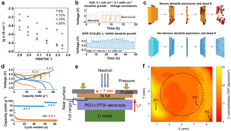 | ||
| Fig. 38 (a) Arrhenius plots of the ISPE-wt% K4BiI7. (b) Symmetric K cell performance using PEO-KFSI electrolyte and ISPE-5% K4BiI7 at a current density of 0.1 mA cm−2, respectively. (c) X-ray CT images of the symmetric K cells structure based on PEO-KFSI (orange) and ISPE (blue) electrolytes. (d) Solid-state PB||K coin cell performance. Reproduced with permission from ref. 287. Copyright 2024, Wiley-VCH. (e) Schematic of the Li||SPE||Li cell for in situ neutron depth profiling measurements. (f) Overall area map of Li in the sample using a 0.5 mm × 0.5 mm pinhole to cover an area of 10 mm × 9 mm. Reproduced with permission from ref. 288. Copyright 2024, Elsevier. | ||
The introduction of hexafluoropropylene (HFP) into the PVDF electrolyte increases the fluorine content and enhances the gel properties.289–291 Due to the addition of a liquid plasticizer, gel polymer electrolytes exhibit high ionic conductivity and excellent interface contact at room temperature.292,293 Very recently, Li et al.294 reported that the mechanical strength of PVDF–HFP can be further improved by introducing UiO-66 through in situ photopolymerization of ethoxylated trimethylolpropane triacrylate monomers. As depicted in the Fig. 39a, the composite polymer electrolyte with a small amount of UiO-66 added (CPE-S) exhibited the highest mechanical strength (stress value of 13.04 MPa) but slightly reduced toughness (strain value of 5.65%). Moreover, the strain value of heavily doped (CPE-L) is only 2.21%, much lower than that of the undoped (CPE-N, 11.73%). Excessive doping of UiO-66 can lead to aggregation, thereby disrupting the integrity of the polymer structure and reducing its mechanical toughness. Due to the increased degree of disorder in the polymer chains caused by an appropriate amount of UiO-66, CPE-S exhibits a wide electrochemical window (over 4.5 V at room temperature) and a high K+ migration number (0.75) (Fig. 39b and c). Benefiting from its high mechanical strength and moderate toughness, CPE-S better suppresses K metal dendrites (Fig. 39d). Accordingly, the PTCDA||CPE-S||K pouch cell is almost unaffected under 180° bending and folding conditions (Fig. 39e).
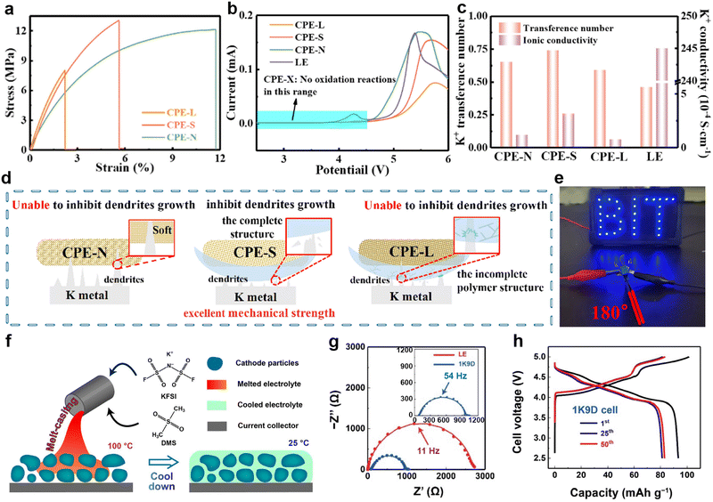 | ||
| Fig. 39 (a) Stress–strain curves of polymer membranes. (b) Linear sweep voltammetry curves of CPE-X and organic liquid electrolyte (LE). (c) Summary of ionic conductivity and K+ transference number for CPE-N, CPE-S, CPE-L, and LE. (d) Schematic illustration of the dendrite inhibition effect. (e) Optical image of the PTCDA||CPE-S||K pouch solid-state potassium-organic batteries powering a LED screen in a folded state. Reproduced with permission from ref. 294. Copyright 2024, Elsevier. (f) Schematic of the melt-casting process with SCOE. (g) Nyquist plots of K||K symmetric cells filled with 1K9D and LE at 25 °C. The inset shows the enlarged view of the 1K9D plot. (h) The 1st, 25th, and 50th charge/discharge profiles of the 1K9D cell. Reproduced with permission from ref. 295. Copyright 2022, Elsevier. | ||
Crystalline organic electrolytes, with their well-structured crystalline salts, offer higher ion conductivity and voltage windows at room temperature, and can achieve close contact with porous electrodes through melt-casting processes, outperforming polymer electrolytes in these aspects. Inspired by the sulfone-based crystalline organic electrolyte (SCOE) used in sodium batteries, Kang et al.295 developed a eutectic SSE mixture of dimethyl sulfoxide (DMS) and KFSI, which was successfully applied in 5 V solid-state potassium batteries (Fig. 39f). As the content of KFSI increases, the conductivity of SCOE slightly rises. Specifically, when the molar ratio of KFSI to DMS is 1![[thin space (1/6-em)]](https://www.rsc.org/images/entities/char_2009.gif) :
:![[thin space (1/6-em)]](https://www.rsc.org/images/entities/char_2009.gif) 9 (1K9D), although its conductivity (4.0 × 10⁻⁴ S cm−1) is slightly lower than that of 2K8D (6.4 × 10⁻⁴ S cm−1 at 25 °C), the charge transfer resistance in the K||K battery with 1K9D is notably smaller than that of liquid electrolytes (Fig. 39g). Due to the enhanced compatibility of 1K9D with K anodes and seamless contact with KVPO4F (KVPF) through the melt-casting process, K||KVPF in 1K9D exhibits a higher initial capacity (93.5 mA h g−1) and CE (ICE: 94.1%) (Fig. 39h), far exceeding those with liquid electrolytes (50.4%).
9 (1K9D), although its conductivity (4.0 × 10⁻⁴ S cm−1) is slightly lower than that of 2K8D (6.4 × 10⁻⁴ S cm−1 at 25 °C), the charge transfer resistance in the K||K battery with 1K9D is notably smaller than that of liquid electrolytes (Fig. 39g). Due to the enhanced compatibility of 1K9D with K anodes and seamless contact with KVPO4F (KVPF) through the melt-casting process, K||KVPF in 1K9D exhibits a higher initial capacity (93.5 mA h g−1) and CE (ICE: 94.1%) (Fig. 39h), far exceeding those with liquid electrolytes (50.4%).
Oxide SSEs typically possess high ionic conductivity, excellent thermal stability, and high voltage windows, allowing them to effectively accommodate various electrode material systems. The K2Fe4O7 electrolyte with open channels synthesized by Yuan et al.300via the hydrothermal method has a total ionic conductivity similar to that of liquid electrolytes of 5.0 × 10⁻² S cm−1 (Fig. 40a). By excluding grain boundary resistance, they tested the K+ conductivity along each axis of the hexagonal single crystal. Since the large pores along the c-axis are blocked by FeO4 tetrahedra or dimers, potassium ions migrate faster along channels parallel to the a-axis or b-axis than along the c-axis (Fig. 40b). The metal battery composed of PB maintains 43% of its initial capacity (76 mA h g−1 at 1C) at a discharge rate of 809 mA cm−2 (120C) (Fig. 40c).
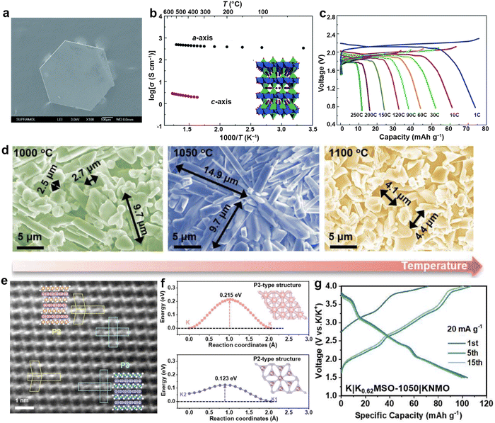 | ||
Fig. 40 (a) SEM image of a large single crystal of K2Fe4O7. (b) Arrhenius conductivity plots of potassium ions along the crystallographic a- and c-axis. The inset shows 3D open framework structure viewed along the crystallographic b-axis. (c) Charge/discharge curves of the all-solid-state battery at different current rates. Reproduced with permission from ref. 300. Copyright 2018, Royal Society of Chemistry. (d) SEM images of the K0.62MSO samples. (e) High-angle annular dark field-scanning transmission electron microscopy image of K0.62MSO-1050. (f) Energy profiles of the migration pathways in P3-K0.62MSO-1050 and P2-K0.62MSO-1050. (g) Voltage curves of the quasi-solid-state battery K||K0.62MSO-1050||KNMO at 20 mA![[thin space (1/6-em)]](https://www.rsc.org/images/entities/char_2009.gif) g−1. Reproduced with permission from ref. 301. Copyright 2024, Wiley-VCH. g−1. Reproduced with permission from ref. 301. Copyright 2024, Wiley-VCH. | ||
It is well-known that ion migration in oxides with prismatic coordination structures is generally easier than in those with octahedral structures. However, there is little research on the differences between P2 and P3 architectures. Zhang et al.301 synthesized K0.62Mg0.54Sb0.46O2 SSEs (K0.62MSO-1000, 1050, and 1100) with varying proportions of P2/P3 phases by adjusting the solid-state reaction synthesis temperature (1000, 1050, and 1100 °C) (Fig. 40d and e). As the temperature increases, the proportion of P2 phase shifts from 42% to 52%, and reaches 100% at 1100 °C. By calculating the ion migration energy barriers in the P2 and P3 structures (Fig. 40f), it was found that the diffusion energy barrier of the P2 phase (0.123 eV) is lower than that of the P3 phase (0.215 eV), consistent with the experimental result that K0.62MSO-1100 exhibits the highest bulk ion conductivity (0.4 × 10⁻³ S cm−1). However, the total K+-ion conductivity of the biphasic K0.62MSO-1050 electrolyte is an order of magnitude higher than that of K0.62MSO-1100. Morphological and atomic structure analysis reveals that the elongated rod-shaped K0.62MSO-1050 facilitates long-distance ion conduction along the (001) plane, effectively avoiding the multi-grain boundary and void resistance present in K0.62MSO-1100. At room temperature, the K0.62MSO-1050 SSE achieves a total K+-ion conductivity of 1.6 × 10⁻⁴ S cm−1 and an oxidation onset potential of up to 6 V. Due to the good stability of the electrolyte–electrode interface, the capacity retention rate of the K||K0.62MSO-1050||KNMO battery (P2-K0.44Ni0.22Mn0.78O2, 65%) after 300 cycles at 50 mA g−1 was higher than that of the liquid electrolyte (49% in 0.8 M KPF6 EC/DEC), and no significant performance degradation was observed during the first 15 cycles at 20 mA g−1 (Fig. 40g).
Sulfide-based SSEs usually exhibit higher interfacial resistance than oxides when used with high-voltage cathodes and alkali metal anodes, due to the lower electronegativity of sulfur compared to oxygen.302,303 Shao et al.304 developed a K3SbSe4-based chalcogenides SSE and, for the first time, confirmed through single-crystal XRD that the material undergoes a transition from a trigonal phase to a cubic phase when heated to 50 °C. Due to the favorable effect of vacancies on potassium ion transport, Ba2+, which is similar in size to potassium ions, is selectively doped into the structure. With the introduction of Ba2+, lattice expansion occurs, and the cubic phase K2.2Ba0.4SbSe4 exhibits the highest room-temperature (20 °C) ionic conductivity of 4.45 × 10⁻⁵ S cm−1 and the lowest activation energy for conduction at 0.28 eV, comparable to other superionic conductors (Fig. 41a). Thanks to the protection of the K anode by the SSE, the K–O2 battery assembled with K2.2Ba0.4SbSe4 electrolyte did not show the yellow byproduct on the K surface, which is typical with the traditional KPF6-DME electrolyte (Fig. 41b). Specifically, the two-chamber K–O2 battery can cycle for 100 cycles without significant capacity attenuation (Fig. 41c).
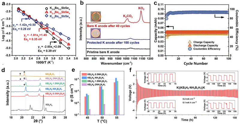 | ||
| Fig. 41 (a) The Arrhenius plots of the K+-ion conductivity for K3−2xBaxSbSe4 (x = 0.2, 0.3, and 0.4) electrolytes. (b) Raman spectra obtained for the samples. The inset shows the optical photos of these samples. (c) Long-term cycling performance and CE of the two-compartment K–O2 battery at a current of 0.05 mA. Reproduced with permission from ref. 304. Copyright 2023, Wiley-VCH. (d) XRD patterns of KB3H8, NH3B3H7, and KB3H8·nNH3B3H7 (n = 0.5, 1, 1.5, and 2). (e) Histograms of the ionic conductivities for KB3H8·nNH3B3H7 (n = 0.5, 1, 1.5, and 2) at given temperatures. (f) Galvanostatic cycling curve of the K||KB3H8·NH3B3H7||K cell at 0.2 mA cm−2. Reproduced with permission from ref. 305. Copyright 2022, American Chemical Society. | ||
Borohydrides such as KCB11H12, KB3H8, and KB11H14 have been designed as SSEs for PMBs due to their thermal/chemical stability and low grain boundary resistance. However, their voltage windows are generally lower than those of oxide and chalcogenide electrolytes. Common methods to enhance the ionic conductivity of borohydrides include modifying crystal structure, introducing neutral molecules such as NH3, CH3NH2, or NH3BH3 to affect cation–anion interactions, and increasing defects. Chen's group has reported three complexes, namely KB3H8·nNH3B3H7 (n = 0.5 and 1), K2B10H10·CO(NH2)2, and KCB9H10·2C3H4N2, to enhance potassium ion conductivity. KB3H8·nNH3B3H7 was synthesized by solid–solid reactions during ball milling.305 XRD patterns showed that when n = 0.5 and 1, the peaks of the raw material disappeared and a new set of diffraction peaks were formed (Fig. 41d). Temperature-variable EIS measurements were conducted on the samples. Due to the coordination of neutral molecule NH3B3H7, the binding interaction between B3H8− and K+ is reduced, leading to an increase in the ionic conductivity of all samples. Among them, KB3H8·NH3B3H7 exhibited the highest ionic conductivity at all temperatures (Fig. 41e). Notably, at 55 °C, KB3H8·NH3B3H7 underwent a structural transition from monoclinic to rhombohedral, which resulted in a conductivity four orders of magnitude higher than that of KB3H8 (4.1 × 10⁻⁸ S cm−1 at 65 °C), reaching 1.3 × 10⁻⁴ S cm−1. As a result, the K||KB3H8·NH3B3H7||K symmetric battery demonstrated good compatibility between the electrolyte and K metal after cycling for 150 h at 0.2 mA cm−2 (Fig. 41f).
Unlike its analogues Li2B10H10 and Na2B10H10, K2B10H10 has a low ion conductivity, making it impractical for actual applications. Lu et al.306 introduced urea molecules via ball milling to weaken the interaction between K+ and B10H102− and accelerate K+ migration. In the structure of K2B10H10·CO(NH2)2, the A and C layers are formed by bridging B10H102− and urea groups (Fig. 42a), while the B layer is formed by K+ cations. Although K2B10H10·CO(NH2)2 has shown improvement compared to K2B10H10, its electronic conductivity at 60 °C and ionic conductivity at 25 °C are only 2.7 × 10⁻⁸ S cm−1 (Fig. 42b and c), and its electrochemical stable potential window of K2B10H10·CO(NH2)2 is 0.83–3.35 V, which still requires further efforts for practical applications. Very recently, the same group designed a new complex, KCB9H10·2C3H4N2, by incorporating highly polar heterocyclic imidazole (C3H4N2) into borohydride (Fig. 42d).307 The ionic conductivity of KCB9H10·2C3H4N2 at room temperature is 5.6 × 10⁻⁵ S cm−1, which is much higher than that of KCB9H10 (1.6 × 10⁻⁸ S cm−1, 30 °C) and other previously reported borohydride. The assembled K||KCB9H10·2C3H4N2||K symmetric battery can stably cycle for 150 h at 0.01 mA cm−2 (Fig. 42e).
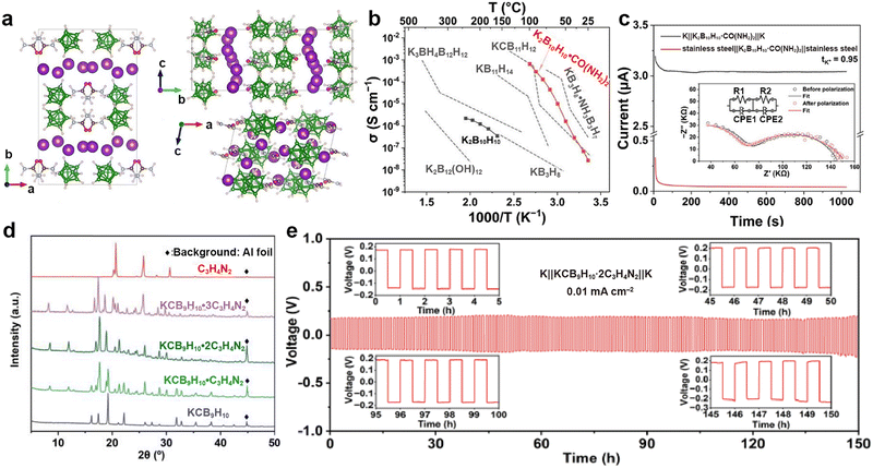 | ||
Fig. 42 (a) Crystal structure of K2B10H10·CO(NH2)2. (b) Temperature dependence of the solid-state K-ion conductivity. (c) Chronoamperometric curves of the K||K2B10H10·CO(NH2)2||K and stainless steel||K2B10H10·CO(NH2)2||stainless steel cells at a polarized voltage of 0.5 V. The inset shows Nyquist plots of a K||K cell before and after polarization. Reproduced with permission from ref. 306. Copyright 2024, American Chemical Society. (d) XRD patterns of KCB9H10, C3H4N2, and KCB9H10·nC3H4N2 (n = 1, 2, and 3). (e) Voltage profiles of the K||K symmetric cell at room temperature and 0.01 mA![[thin space (1/6-em)]](https://www.rsc.org/images/entities/char_2009.gif) cm−2. Reproduced with permission from ref. 307. Copyright 2024, Wiley-VCH. cm−2. Reproduced with permission from ref. 307. Copyright 2024, Wiley-VCH. | ||
4. Conclusions and future perspectives
K metal, used as the anode material in PMBs, shows significant advantages in high-energy-density battery systems due to its abundant natural resources, low cost, exceptional theoretical specific capacity, and low standard electrode potential. Nevertheless, the practical deployment of K metal anodes faces numerous challenges, similar to those encountered by lithium metal anodes. These challenges mainly include an uncontrollable K nucleation process, continuous dendrite growth, an unstable SEI, and large volume expansion. These factors together impede the progress of K metal anodes towards practical applications.Currently, theoretical research on the solvation/desolvation mechanism, diffusion kinetics, nucleation mechanism, and deposition/stripping process of potassium ions in PMBs remains in its early stages (Fig. 43). Given the similarity between alkali metals, various theoretical frameworks, such as the SH model, Gibbs free energy theory, space charge model, thin film growth model, and stress-driven model, have been employed to infer and analyze the nucleation and deposition behavior of K metals. However, it must be acknowledged that there are substantial differences in the physical and chemical properties between K metal anodes and electrolytes and those of lithium metal anodes and electrolytes. These discrepancies lead to unique challenges in the surface diffusion barrier, interface energy, and SEI composition and mechanical properties of potassium metal. For example, the lower surface diffusion barrier of K metal allows K dendrites to induce self-heating effects at a current density of 1.5 mA cm−2, which is one order of magnitude lower than that of lithium metal.308 In addition, the potassium-based SEI is more unstable than the lithium-based SEI, exhibiting an impedance value an order of magnitude higher than that of lithium after cycling in ester electrolytes.
In response to the above challenges, researchers are exploring various strategies, such as designing 3D porous potassium-friendly frameworks with large specific surface areas, constructing artificial SEI and CEI layers, and developing electrolytes suitable for potassium metal. It is worth noting that room-temperature liquid Na–K alloy has gained widespread attention as a novel dendrite-free anode material, which can theoretically suppress the formation of dendrites. However, the high surface tension and fluidity of the liquid alloy pose challenges to substrate composites and battery assembly sealing. Moreover, besides the aforementioned strategies for inhibiting dendrite growth, utilizing oxidative active substances to convert dendrites into electroactive potassium ions and reactivate isolated K is also crucial for enhancing the CE of PMBs.287 From the perspective of space charge theory, reducing local current density has become an effective means of delaying dendrite growth. Regarding 3D skeleton or current collector modification, the enhancement of potassium affinity aims to change the interfacial energy of the substrate, thereby avoiding island-like nucleation of K and inhibiting dendrites. Nevertheless, it cannot be ignored that the high surface area of the 3D structure will exacerbate the consumption of electrolytes, resulting in low initial CE.
In the design of artificial SEI and barrier layers, separators, and electrolytes for PMBs, the composition, mechanical properties, and ionic conductivity of the interfaces are paramount considerations in current research. The low melting point and high air sensitivity of K hinder the application of CVD-based coating technology. Therefore, more scientific approaches are required, such as forming carbon intercalation compounds and alloying/conversion, to construct artificial SEI and barrier layers, respectively. The ideal multifunctional intermediate layer should not only meet the requirements for high ion transport but also have potassium affinity sites to effectively guide uniform potassium ion flux. On the other hand, the interface layer should have a high Young's modulus to physically suppress dendrite penetration or high elasticity to accommodate volume changes, thus avoiding sustained side reactions stemming from interface rupture.309 To reduce damage to common commercial separators, separator modification mostly uses adhesive coating methods to enhance mechanical properties and indirectly affect the composition of the interface layer. The modification of Celgard separator focuses on improving its wettability with electrolytes and accelerating kinetics processes. However, the modified SEI obtained through interface modification or separator regulation still faces challenges when subjected to high current density and high cutoff capacity.
The design of electrolyte compositions focuses on improving potassium ion conductivity and forming stable SEI and CEI on electrode surfaces. The regulation of liquid electrolytes involves the selection of salts, additives, and solvents. Potassium salts or additives with low reduction potentials are usually chosen to form an SEI layer primarily through anion decomposition, thereby inhibiting the growth of K dendrites. The design of solvents, including the development of cosolvents and novel solvents, requires faster desolvation of potassium ions and promotes the preferential involvement of anions in the construction of SEI layers. Solvents with weak solvation capability also help to address the issue of co-intercalation of potassium ions and solvents in graphite negative electrodes, laying the foundation for future commercial applications. Specifically, the addition of cosolvents aims to create a unique solvation structure with localized high concentrations to meliorate the low ion conductivity present in HCEs. The development of SSEs is based on considerations of safety and thermal stability, yet their main problem lies in low ionic conductivity. Additionally, cracks often arise within the electrode–electrolyte composite due to changes in the volume of active materials or electrolyte decomposition, leading to failure. Currently, SSEs for PMBs include polymers, oxides, borohydrides, etc. The increase in conductivity of polymers relies on fillers to alter the disorder of polymer chains.310 Ion migration of oxides and borohydrides depends on the open channels of crystals, with oxide electrolytes capable of achieving a wider voltage window than liquid electrolytes. Although the low conductivity of borohydrides at room temperature makes them unsuitable for current applications, they demonstrate excellent ionic conductivity at high temperatures.
Given the differences in SEI formed in symmetric and K||Cu asymmetric batteries compared to PMBs, focusing solely on the stability of the K anode is insufficient; compatibility with the cathode also needs to be fully considered. In stabilizing the K anode interface, ether-based electrolytes have more advantages than ester-based electrolytes but can decompose and corrode the current collector in high-voltage systems. Therefore, most successfully assembled PMBs currently use the PTCDA cathode with low cut-off voltage. As the anode CE improves, PMBs exhibit more stable cycling performance and higher capacity retention. To achieve high energy density systems, Prussian blue analogues, layered oxides, and polyanion compounds are used as cathodes for anode-free PMBs. The construction of artificial interface layers and the optimization of electrolytes are also pivotal in forming stable CEI under high voltage. The design of Na–K liquid alloy anodes and gel polymer electrolytes holds potential applications in stretchable or flexible energy storage systems. Furthermore, addressing the challenges posed by side reactions, dendrite growth, and volume changes between K metal and electrolytes, as well as the importance of dissolved oxygen for K–O2 batteries, is equally crucial. The design of high ion mobility SSEs can not only effectively stabilize the SEI layer but also prevent O2 diffusion to the anode side, thereby further improving the battery performance.
To further explore and achieve high-efficiency PMBs, advanced characterization techniques and multi-scale modelling methods are indispensable for elucidating the microstructure of K metal dendrites and the evolution mechanism of SEI interfaces. Techniques such as XRD, FTIR, XPS, Raman spectroscopy, NMR, and TOF-SIMS analysis provide powerful means for structural analysis. In terms of morphology observation, AFM, SEM, optical microscopy, and TEM play an irreplaceable role in depicting K deposition/stripping and the SEI/CEI layer structure. Especially, AFM has extensive applications in evaluating the mechanical properties of SEI layers or separator surfaces. Recently, the introduction of X-ray tomography and neutron diffraction techniques has enabled 3D imaging of K metal anodes. Additionally, the proposal of the titration gas chromatography method offers the possibility for quantitative analysis of deactivated K metal detached from the anode in SEI. At the theoretical research level, methods such as molecular dynamics simulation and finite element analysis have been used to explore ion migration pathways, interface energy barriers, electric field distribution, ion concentration distribution, and SEI stress states in PMBs. In the future, the exploration of machine learning algorithms is anticipated to further optimize material modelling, efficiently screen highly conductive materials, and accurately predict battery energy density and safety.
In summary, although K metal has significant merits as an anode material for PMBs, its practical application still faces many challenges. Through advanced characterization techniques, multi-scale modelling methods, and a series of innovative strategies, researchers are gradually overcoming these challenges and promoting the development of PMBs towards high performance, high safety, and high stability. In the future, with the continuous deepening of research and advances in technology, PMBs are expected to become an important component of the new generation of high-energy density energy storage systems.
Data availability
This review does not include any original research results, software, or code, nor were any new data generated or analyzed. Additional information about the review is available upon request from the authors.Conflicts of interest
There are no conflicts to declare.Acknowledgements
This work was supported by the National Natural Science Foundation of China (22479078 and 22179063). D. H. Kim acknowledges the financial support from the National Research Foundation of Korea Grant funded by the Korean Government (NRF-2020R 1A 2C 3003958).References
- W. Wang, M. O. Tadé and Z. Shao, Chem. Soc. Rev., 2015, 44, 5371–5408 RSC
.
- Y. Xu, Y. Du, H. Chen, J. Chen, T. Ding, D. Sun, D. H. Kim, Z. Lin and X. Zhou, Chem. Soc. Rev., 2024, 53, 7202–7298 RSC
.
- B. Dunn, H. Kamath and J.-M. Tarascon, Science, 2011, 334, 928–935 CrossRef CAS PubMed
.
- K. Yuan, Q. Chen, A. Zhang, N. Xiao, X. Zou and Z. Lin, J. Mater. Chem. A, 2024, 12, 2456–2464 RSC
.
- Q. Hassan, A. Z. Sameen, H. M. Salman, M. Jaszczur and A. K. Al-Jiboory, J. Energy Storage, 2023, 72, 108404 CrossRef
.
- E. R. Mahoney, M. Boudjelel, H. Shavel, M. D. Krzyaniak, M. R. Wasielewski and C. A. Malapit, J. Am. Chem. Soc., 2025, 147, 1381–1386 CrossRef CAS PubMed
.
- E. B. Yılmaz, E. O. Eren, T. Horner, Z. Song, Y. Sheidaei, I. Siewert, E. Senokos and P. Giusto, Angew. Chem., Int. Ed., 2025, 64, e202422714 Search PubMed
.
- Y. Yi, L. Chang, B. Wu, J. Zhao, H. Peng, L. Li and A. Wang, Energy Technol., 2024, 12, 2301129 CrossRef
.
- P. M. Attia, E. Moch and P. K. Herring, Nat. Commun., 2025, 16, 611 CrossRef CAS PubMed
.
- L. Tang, H. Peng, J. Kang, H. Chen, M. Zhang, Y. Liu, D. H. Kim, Y. Liu and Z. Lin, Chem. Soc. Rev., 2024, 53, 4877–4925 RSC
.
- X. Zhou, X. Li, J. Pang and Z. Lei, Coord. Chem. Rev., 2025, 523, 216255 CrossRef CAS
.
- J. Liao, Z. Yuan, Q. Hu, X. Sheng, L. Song, Y. Xu, Y. Du and X. Zhou, Angew. Chem., Int. Ed., 2024, 63, e202409145 CrossRef CAS PubMed
.
- S. Koohi-Fayegh and M. A. Rosen, J. Energy Storage, 2020, 27, 101047 CrossRef
.
- L. Duan, Y. Zhang, H. Tang, J. Liao, G. Zhou and X. Zhou, Adv. Mater., 2025, 37, 2411426 CrossRef CAS PubMed
.
- J. Chen, H. Lan, S. Wang, X. Liu, Q. Zhu, X. Zhang, M. Tang, S. Dong, J. Yang, M. Kurbanov, L. Guo and H. Wang, J. Am. Chem. Soc., 2025, 147, 2393–2402 CrossRef CAS PubMed
.
- N. Chen, Y. Pang, Z. Liu, N.-L. Shen, H. Chen, W. Zhang, Q. Lai, X. Yi and Y. Liang, ACS Nano, 2024, 18, 32205–32214 CrossRef CAS PubMed
.
- W. A. N. Shun-ning and C. A. I. Ping, Battery, 2009, 39, 161–163 Search PubMed
.
- J. Fan, H. Teng and Y. Wang, Sustainability, 2022, 14, 10016 CrossRef
.
- R. Schmuch, R. Wagner, G. Hörpel, T. Placke and M. Winter, Nat. Energy, 2018, 3, 267–278 CrossRef CAS
.
- W. Yao, K. Liao, T. Lai, H. Sul and A. Manthiram, Chem. Rev., 2024, 124, 4935–5118 CrossRef CAS PubMed
.
- C. Wei, Y. Tao, H. Fei, Y. An, Y. Tian, J. Feng and Y. Qian, Energy Storage Mater., 2020, 30, 206–227 CrossRef
.
- X. Zhao, J. Fu, M. Chen, Y. Wang, C. Huang, K. Qian, G. Feng, B. Li, D. Zhou and F. Kang, J. Am. Chem. Soc., 2025, 147, 2714–2725 CrossRef CAS PubMed
.
- J. Xiao, X. Li, K. Tang, D. Wang, M. Long, H. Gao, W. Chen, C. Liu, H. Liu and G. Wang, Mater. Chem. Front., 2021, 5, 3735–3764 RSC
.
- J. Liao, C. Shao, J. Han, Z. Yuan, Q. Hu, Y. Du, S. Guo, X. Zhou and H. Zhou, Energy Environ. Sci., 2024, 17, 7362–7371 RSC
.
- L. Duan, C. Shao, J. Liao, L. Song, Y. Zhang, R. Li, S. Guo, X. Zhou and H. Zhou, Angew. Chem., Int. Ed., 2024, 63, e202400868 CrossRef CAS PubMed
.
- Y. Lv, J. Sun, F. Kang, D. Yan, H. Liu, X. Li, Z. Yuan, Q. Zhang and X. Zhou, Sci. Bull., 2024, 69, 3340–3344 CrossRef CAS PubMed
.
- L. Song, S. Zhang, L. Duan, R. Li, Y. Xu, J. Liao, L. Sun, X. Zhou and Z. Guo, Angew. Chem., Int. Ed., 2024, 63, e202405648 CrossRef CAS PubMed
.
- A. Eftekhari, J. Power Sources, 2004, 126, 221–228 CrossRef CAS
.
- W. Zhang, Y. Liu and Z. Guo, Sci. Adv., 2019, 5, eaav7412 CrossRef CAS PubMed
.
- M. Xu, Z. Xin, J. Wang, T. W. Tang, Y. Li, Y. Li, T.-H. Kim and Z. Luo, Energy Mater., 2024, 4, 400066 CrossRef
.
- J. Popovic, J. Electrochem. Soc., 2022, 169, 030510 CrossRef CAS
.
- J. Kuepper, X. Li and U. Simon, J. Electrochem. Soc., 2022, 169, 060539 CrossRef CAS
.
- Z. Jiang, N. Li, L. Li, F. Tan, J. Huang and S. Huang, Adv. Mater., 2024, 36, 2311127 CrossRef CAS PubMed
.
- J. Park, J. Lee, M. H. Alfaruqi, W. J. Kwak, J. Kim and J. Y. Hwang, J. Mater. Chem. A, 2020, 8, 16718–16737 RSC
.
- Q. Zhao, Y. Hu, K. Zhang and J. Chen, Inorg. Chem., 2014, 53, 9000–9005 CrossRef CAS PubMed
.
- X. Yuan, B. Zhu, J. Feng, C. Wang, X. Cai, K. Qiao and R. Qin, Small, 2020, 16, 2003386 CrossRef CAS PubMed
.
- S. Ye, N. Yao, X. Chen, M. Ma, L. Wang, Z. Chen, Y. Yao, Q. Zhang and Y. Yu, Angew. Chem., Int. Ed., 2023, 62, e202307728 CrossRef CAS PubMed
.
- Y.-J. Lei, H.-L. Yang, Y. Liang, H.-W. Liu, B. Zhang, L. Wang, W.-H. Lai, Y.-X. Wang, H.-K. Liu and S.-X. Dou, Adv. Energy Mater., 2022, 12, 2202523 CrossRef CAS
.
- Q. Zhang, Q. Huang, S.-M. Hao, S. Deng, Q. He, Z. Lin and Y. Yang, Adv. Sci., 2022, 9, 2103798 CrossRef CAS PubMed
.
- H. Huang, J. Wang, X. Yang, R. Hu, J. Liu, L. Zhang and M. Zhu, Angew. Chem., Int. Ed., 2020, 59, 14504–14510 CrossRef CAS PubMed
.
- Z.-X. Qi, S.-N. Luo, J.-F. Ruan, T. Yuan, Y.-P. Pang, J.-H. Yang and S.-Y. Zheng, New Carbon Mater., 2024, 39, 824–843 CrossRef CAS
.
- C. Ye, J. Shan, D. Chao, P. Liang, Y. Jiao, J. Hao, Q. Gu, K. Davey, H. Wang and S.-Z. Qiao, J. Am. Chem. Soc., 2021, 143, 16902–16907 CrossRef CAS PubMed
.
- S. Zhang, Y. Kong, Y. Gu, R. Bai, M. Li, S. Zhao, M. Ma, Z. Li, L. Zeng, D. Qiu, Q. Zhang, M. Luo, L. Gu, Y. Yu, S. Guo and J. Zhang, J. Am. Chem. Soc., 2024, 146, 4433–4443 CrossRef CAS PubMed
.
- W. Xie, Y. Liu, Y. Yan, M. Yang, M. Zhang, B. Liu, H. Li, H. Chen and Z. Lin, Energy Storage Mater., 2023, 59, 102783 CrossRef
.
- D. Aurbach, B. D. McCloskey, L. F. Nazar and P. G. Bruce, Nat. Energy, 2016, 1, 16128 CrossRef CAS
.
- C. Sun, L. Gao, W. Rong, Y. Yang and Y. Bai, Chem. Eng. J., 2025, 503, 158148 CrossRef CAS
.
- P. G. Bruce, S. A. Freunberger, L. J. Hardwick and J.-M. Tarascon, Nat. Mater., 2012, 11, 19–29 CrossRef CAS PubMed
.
- X. Ren and Y. Wu, J. Am. Chem. Soc., 2013, 135, 2923–2926 CrossRef CAS PubMed
.
- N. Xiao, X. Ren, W. D. McCulloch, G. Gourdin and Y. Wu, Acc. Chem. Res., 2018, 51, 2335–2343 CrossRef CAS PubMed
.
- L. Qin, L. Schkeryantz, J. Zheng, N. Xiao and Y. Wu, J. Am. Chem. Soc., 2020, 142, 11629–11640 CrossRef CAS PubMed
.
- N. Xiao, J. Zheng, G. Gourdin, L. Schkeryantz and Y. Wu, ACS Appl. Mater. Interfaces, 2019, 11, 16571–16577 CrossRef CAS PubMed
.
- L. Zhang, Y. Tang, Q. Liu, T. Yang, C. Du, P. Jia, Z. Wang, Y. Tang, Y. Li, T. Shen and J. Huang, Nano Energy, 2018, 53, 544–549 CrossRef CAS
.
- J. Lin, W. Song, C. Xiao, J. Ding, Z. Huang, C. Zhong, J. Ding and W. Hu, Carbon Energy, 2023, 5, e313 CrossRef CAS
.
- X. Li, G. Qi, J. Zhang, J. Cheng and B. Wang, Adv. Funct. Mater., 2022, 32, 2105029 CrossRef CAS
.
- Y. Lu, Y. Cai, Q. Zhang, Y. Ni, K. Zhang and J. Chen, Angew. Chem., Int. Ed., 2021, 60, 9540–9545 CrossRef CAS PubMed
.
- D. Liu, J. Shen, Z. Jian and X. Cai, Energy Mater., 2023, 3, 300028 CAS
.
- H. Zhuang, H. Xiao, T. Zhang, F. Zhang, P. Han, M. Xu, W. Dai, W. Chen and Q. Gao, Appl. Catal., B, 2025, 365, 124916 CrossRef CAS
.
- S. Sunny, S. Suriyakumar, A. S. Sajeevan and M. M. Shaijumon, J. Phys. Energy, 2024, 6, 022004 CrossRef CAS
.
- P. Liu and D. Mitlin, Acc. Chem. Res., 2020, 53, 1161–1175 CrossRef CAS PubMed
.
- H. Zhao, J. Xu, D. Yin and Y. Du, Chem. – Eur. J., 2018, 24, 18220–18234 CrossRef CAS PubMed
.
- S. S. Shinde, N. K. Wagh, S.-H. Kim and J.-H. Lee, Adv. Sci., 2023, 10, 2304235 CrossRef CAS PubMed
.
- S. Li, H. Zhu, C. Gu, F. Ma, W. Zhong, M. Liu, H. Zhang, Z. Zeng, S. Cheng and J. Xie, ACS Energy Lett., 2023, 8, 3467–3475 CrossRef CAS
.
- D. J. Astley, J. A. Harrison and H. R. Thirsk, Trans. Faraday Soc., 1968, 64, 192–201 RSC
.
- G. J. Hills, D. J. Schiffrin and J. Thompson, Electrochim. Acta, 1974, 19, 657–670 CrossRef CAS
.
- B. Scharifker and G. Hills, Electrochim. Acta, 1983, 28, 879–889 CrossRef CAS
.
- E. R. Cooper, M. Li, I. Gentle, Q. Xia and R. Knibbe, Angew. Chem., Int. Ed., 2023, 62, e202309247 CrossRef CAS PubMed
.
- D. R. Ely and R. E. García, J. Electrochem. Soc., 2013, 160, A662 CrossRef CAS
.
- X. Chen, Y.-K. Bai, X. Shen, H.-J. Peng and Q. Zhang, J. Energy Chem., 2020, 51, 1–6 CrossRef
.
- S. Ye, L. Wang, F. Liu, P. Shi and Y. Yu, eScience, 2021, 1, 75–82 CrossRef
.
- K. Raeissi, A. Saatchi and M. A. Golozar, J. Appl. Electrochem., 2003, 33, 635–642 CrossRef CAS
.
- B. Thirumalraj, T. T. Hagos, C.-J. Huang, M. A. Teshager, J.-H. Cheng, W.-N. Su and B.-J. Hwang, J. Am. Chem. Soc., 2019, 141, 18612–18623 CrossRef CAS PubMed
.
- J. Rizell, W. Chrobak, N. Mozhzhukhina, S. Xiong and A. Matic, J. Electrochem. Soc., 2024, 171, 020517 CrossRef CAS
.
- H. Wang, E. Matios, J. Luo and W. Li, Chem. Soc. Rev., 2020, 49, 3783–3805 RSC
.
- D. T. Wu, Solid State Phys., 1996, 50, 37–187 Search PubMed
.
- A. Katselas, R. Parin and C. Neto, Adv. Mater. Interfaces, 2022, 9, 2200246 CrossRef CAS
.
- M.-X. Zhang, P. M. Kelly, M. A. Easton and J. A. Taylor, Acta Mater., 2005, 53, 1427–1438 CrossRef CAS
.
- H. Cai, S. Bi, R. Wang, L. Liu and Z. Niu, Angew. Chem., Int. Ed., 2022, 61, e202205472 CrossRef CAS PubMed
.
- A. Pei, G. Zheng, F. Shi, Y. Li and Y. Cui, Nano Lett., 2017, 17, 1132–1139 CrossRef CAS PubMed
.
- Q. Xu, Y. Yang and H. Shao, Phys. Chem. Chem. Phys., 2015, 17, 20398–20406 RSC
.
- M. K. Aslam, Y. Niu, T. Hussain, H. Tabassum, W. Tang, M. Xu and R. Ahuja, Nano Energy, 2021, 86, 106142 CrossRef CAS
.
- X. Wang, Z. Chen, X. Xue, J. Wang, Y. Wang, D. Bresser, X. Liu, M. Chen and S. Passerini, Nano Energy, 2025, 133, 110439 CrossRef CAS
.
- J. Sun, F. Kang, D. Yan, T. Ding, Y. Wang, X. Zhou and Q. Zhang, Angew. Chem., Int. Ed., 2024, 63, e202406511 CrossRef CAS PubMed
.
- B. Zhang, J. Yao, C. Wu, Y. Li, J. Liu, J. Wang, T. Xiao, T. Zhang, D. Cai, J. Wu, Z. W. Seh, S. Xi, H. Wang, W. Sun, H. Wan and H. J. Fan, Nat. Commun., 2025, 16, 71 CrossRef PubMed
.
- P. Bai, J. Li, F. R. Brushett and M. Z. Bazant, Energy Environ. Sci., 2016, 9, 3221–3229 RSC
.
- S. Baek, T. Jung, S. Jie, M. Kim and B. Lee, Int. J. Energy Res., 2023, 2023, 6680001 Search PubMed
.
- H. J. S. Sand, London, Edinburgh Dublin Philos. Mag. J. Sci., 1901, 1, 45–79 CrossRef CAS
.
- J. N. Chazalviel, Phys. Rev. A:At., Mol., Opt. Phys., 1990, 42, 7355–7367 CrossRef CAS PubMed
.
- J. T. Kim and J. Jorné, J. Electrochem. Soc., 1980, 127, 8–15 CrossRef CAS
.
- C. Monroe and J. Newman, J. Electrochem. Soc., 2003, 150, A1377–A1384 CrossRef CAS
.
- X. Wang, W. Zeng, L. Hong, W. Xu, H. Yang, F. Wang, H. Duan, M. Tang and H. Jiang, Nat. Energy, 2018, 3, 227–235 CrossRef CAS
.
- J. Gu, Y. Shi, Z. Du, M. Li and S. Yang, Adv. Energy Mater., 2023, 13, 2302091 CrossRef CAS
.
- M. Jäckle and A. Groß, J. Chem. Phys., 2014, 141, 174710 CrossRef PubMed
.
- M. Jäckle, K. Helmbrecht, M. Smits, D. Stottmeister and A. Groß, Energy Environ. Sci., 2018, 11, 3400–3407 RSC
.
- X. Liu, G. Wang, Z. Lv, A. Du, S. Dong and G. Cui, Adv. Mater., 2024, 36, 2306395 CrossRef CAS PubMed
.
- P. Liu, Y. Wang, Q. Gu, J. Nanda, J. Watt and D. Mitlin, Adv. Mater., 2020, 32, 1906735 CrossRef CAS PubMed
.
- X. Shen, R. Zhang, C. Zhao, P. Wu, Y. Zhang, J. Zhang, L. Fan, Q. Liu, A. Chen and Q. Zhang, Energy Storage Sci. Technol., 2022, 11, 2781–2797 Search PubMed
.
- K. R. Hebert, J. Electrochem. Soc., 2023, 170, 050526 CrossRef CAS
.
- X. Zou, C. Ma, T. Xu, R. Li, H. Wang and F. Chen, J. Energy Storage, 2023, 74, 109483 CrossRef
.
- D. Tewari and P. P. Mukherjee, J. Mater. Chem. A, 2019, 7, 4668–4688 RSC
.
- J. Wang, Y. Zuo, M. Chen, K. Chen, Z. Chen, Z. Lu and L. Si, Electrochim. Acta, 2022, 433, 141211 CrossRef CAS
.
- C. Fang, J. Li, M. Zhang, Y. Zhang, F. Yang, J. Z. Lee, M.-H. Lee, J. Alvarado, M. A. Schroeder, Y. Yang, B. Lu, N. Williams, M. Ceja, L. Yang, M. Cai, J. Gu, K. Xu, X. Wang and Y. S. Meng, Nature, 2019, 572, 511–515 CrossRef CAS PubMed
.
- E. Peled, J. Electrochem. Soc., 1979, 126, 2047 CrossRef CAS
.
- E. Peled, J. Power Sources, 1983, 9, 253–266 CrossRef CAS
.
- E. Peled, D. Golodnitsky and G. Ardel, J. Electrochem. Soc., 1997, 144, L208 CrossRef CAS
.
- R. L. Sacci, J. L. Banuelos, G. M. Veith, K. C. Littrel, Y. Q. Cheng, C. U. Wildgruber, L. L. Jones, A. J. Ramirez-Cuesta, G. Rother and N. J. Dudney, J. Phys. Chem. C, 2015, 119, 9816–9823 CrossRef CAS
.
- H. Zhang, C. Shen, Y. Huang and Z. Liu, Appl. Surf. Sci., 2021, 537, 147983 CrossRef CAS
.
- J. B. Goodenough and Y. Kim, Chem. Mater., 2010, 22, 587–603 CrossRef CAS
.
- L.-K. Zhao, X.-W. Gao, T.-Z. Ren, D. Wang, D.-W. Wang, Z.-M. Liu, H. Chen and W.-B. Luo, Rare Met., 2024, 43, 1435–1460 CrossRef CAS
.
- Y. Gao, X. Du, Z. Hou, X. Shen, Y.-W. Mai, J.-M. Tarascon and B. Zhang, Joule, 2021, 5, 1860–1872 CrossRef CAS
.
- H. Wang, D. Zhai and F. Kang, Energy Environ. Sci., 2020, 13, 4583–4608 RSC
.
- J. Hu, H. Wang, S. Wang, Y. Lei, L. Qin, X. Li, D. Zhai, B. Li and F. Kang, Energy Storage Mater., 2021, 36, 91–98 CrossRef
.
- R. Zhou, H. Tan, Y. Gao, Z. Hou, X. Du and B. Zhang, Carbon, 2022, 186, 141–149 CrossRef CAS
.
- T. Li, X.-Q. Zhang, P. Shi and Q. Zhang, Joule, 2019, 3, 2647–2661 CrossRef CAS
.
- X. Shen, H. Liu, X.-B. Cheng, C. Yan and J.-Q. Huang, Energy Storage Mater., 2018, 12, 161–175 CrossRef
.
- S. Jurng, Z. L. Brown, J. Kim and B. L. Lucht, Energy Environ. Sci., 2018, 11, 2600–2608 RSC
.
- W. Liu, P. Liu and D. Mitlin, Adv. Energy Mater., 2020, 10, 2002297 CrossRef CAS
.
- C.-B. Chang, Y.-Y. Tseng, Y.-R. Lu, Y.-C. Yang and H.-Y. Tuan, Adv. Funct. Mater., 2024, 34, 2411193 CrossRef CAS
.
- J. Nanda, G. Yang, T. Hou, D. N. Voylov, X. Li, R. E. Ruther, M. Naguib, K. Persson, G. M. Veith and A. P. Sokolov, Joule, 2019, 3, 2001–2019 CrossRef CAS
.
- Y. Zhou, M. Su, X. Yu, Y. Zhang, J.-G. Wang, X. Ren, R. Cao, W. Xu, D. R. Baer, Y. Du, O. Borodin, Y. Wang, X.-L. Wang, K. Xu, Z. Xu, C. Wang and Z. Zhu, Nat. Nanotechnol., 2020, 15, 224–230 CrossRef CAS PubMed
.
- F. Jeschull, E. Kataev, I. Panasenko, C. Njel, R. Félix and J. Maibach, Adv. Energy Mater., 2025, 15, 2403811 Search PubMed
.
- H. Tan and X. Lin, Molecules, 2023, 28, 823 CrossRef CAS PubMed
.
- Q. Liu, Y.-H. Feng, X. Zhu, M. Liu, L. Yu, G.-X. Wei, X.-Y. Fan, X. Ji, P.-F. Wang and H. Xin, Nano Energy, 2024, 123, 109389 CrossRef CAS
.
- D. Wu, C. Zhu, H. Wang, J. Huang, G. Jiang, Y. Yang, G. Yang, D. Tang and J. Ma, Angew. Chem., Int. Ed., 2024, 63, e202315608 CrossRef CAS PubMed
.
- K. Luo, Z. Wang, Y. Mo, J. Ke, W. Zhou, K. Wang, S. Chen, P. Gao, A. Hu and J. Liu, Adv. Funct. Mater., 2024, 34, 2311364 CrossRef CAS
.
- Q. Li, Y. Wang, X. Wang, X. Sun, J.-N. Zhang, X. Yu and H. Li, ACS Appl. Mater. Interfaces, 2020, 12, 2319–2326 CrossRef CAS PubMed
.
- C. Yan, R. Xu, Y. Xiao, J.-F. Ding, L. Xu, B.-Q. Li and J.-Q. Huang, Adv. Funct. Mater., 2020, 30, 1909887 CrossRef CAS
.
- S. Zhao, G. Li, B. Zhang, S. Zhang, Y. Liu, J. Zhou, M. Luo and S. Guo, Adv. Mater., 2024, 36, 2405184 CrossRef CAS PubMed
.
- W. M. Seong, K. Yoon, M. H. Lee, S.-K. Jung and K. Kang, Nano Lett., 2019, 19, 29–37 CrossRef CAS PubMed
.
- D. Chen, M. A. Mahmoud, J.-H. Wang, G. H. Waller, B. Zhao, C. Qu, M. A. El-Sayed and M. Liu, Nano Lett., 2019, 19, 2037–2043 CrossRef CAS PubMed
.
- Z. Zhang, C. Qin, K. Wang, X. Han, J. Li, M. Sui and P. Yan, J. Energy Chem., 2023, 81, 192–199 CrossRef CAS
.
- J.-N. Zhang, Q. Li, Y. Wang, J. Zheng, X. Yu and H. Li, Energy Storage Mater., 2018, 14, 1–7 CrossRef
.
- B. Lee, E. Paek, D. Mitlin and S. W. Lee, Chem. Rev., 2019, 119, 5416–5460 CrossRef CAS PubMed
.
- L. Zhang, X. Xia, Y. Zhong, D. Xie, S. Liu, X. Wang and J. Tu, Adv. Mater., 2018, 30, 1804011 CrossRef PubMed
.
- J. Wu, Z. Xue, L. Yuan, J. Ye, Q. Huang, L. Fu and Y. Wu, J. Energy Chem., 2022, 71, 313–323 CrossRef CAS
.
- T. Ding, Y. Chen, W. Yuan, L. Li, P. Mou, Y. Luo, H. Yu, L. Yan, J. Shu and L. Zhang, Chem. Eng. J., 2023, 475, 146185 CrossRef CAS
.
- Y. Xie, J. Hu and Z. Zhang, J. Electroanal. Chem., 2020, 856, 113676 CrossRef CAS
.
- M. Shao, N. Wu, T. Chen, X. Han, Y. Shen, W. Zhang, B. Zheng, S. Li and F. Huo, Chin. Chem. Lett., 2023, 34, 107767 CrossRef CAS
.
- L. Zhao, Y. Tao, W.-H. Lai, Z. Hu, J. Peng, Y. Lei, Y. Cao, S.-L. Chou, Y.-X. Wang, H. K. Liu and S. X. Dou, Adv. Funct. Mater., 2024, 34, 2302026 CrossRef CAS
.
- A. C. Baclig, G. McConohy, A. Poletayev, A. Michelson, N. Kong, J.-H. Lee, W. C. Chueh and J. Rugolo, Joule, 2018, 2, 1287–1296 CrossRef CAS
.
- Y. Cheng, C. Lin, C. Luo, W. Liu and M.-S. Wang, Small Struct., 2023, 4, 2300097 CrossRef CAS
.
- L. Xue, H. Gao, W. Zhou, S. Xin, K. Park, Y. Li and J. B. Goodenough, Adv. Mater., 2016, 28, 9608–9612 CrossRef CAS PubMed
.
- L. Xue, W. Zhou, S. Xin, H. Gao, Y. Li, A. Zhou and J. B. Goodenough, Angew. Chem., Int. Ed., 2018, 57, 14184–14187 CrossRef CAS PubMed
.
- T. Luo, Q. Zhao, Y. Liu, W. Meng, Q. Sun, L. Dai, S. Liu and L. Wang, EcoMat, 2022, 4, e12203 CrossRef CAS
.
- H. Yang, Q. Li, L. Sun, S. Zhai, X. Chen, Y. Tan, X. Wang, C. Liu, W.-Q. Deng and H. Wu, Small, 2024, 20, 2306572 CrossRef CAS PubMed
.
- J.-L. Zhou, L.-K. Zhao, Y. Lu, X.-W. Gao, Y. Chen, Z.-M. Liu, Q.-F. Gu and W.-B. Luo, Adv. Funct. Mater., 2024, 34, 2403754 CrossRef CAS
.
- M. Ye, J.-Y. Hwang and Y.-K. Sun, ACS Nano, 2019, 13, 9306–9314 CrossRef CAS PubMed
.
- J. Zhang, Y. Li, L. Zhu, X. Wang and J. Tu, Chem. Eng. J., 2022, 449, 137659 CrossRef CAS
.
- J. Xiong, M. Ye, Z. Wang, J. Chen, Y. Zhang, Y. Tang and C. C. Li, Chem. Eng. J., 2022, 442, 135927 CrossRef CAS
.
- J.-F. Wu, W. Zhou, Z. Wang, W.-W. Wang, X. Lan, H. Yan, T. Shi, R. Hu, X. Cui, C. Xu, X. He, B.-W. Mao, T. Zhang and J. Liu, Adv. Mater., 2023, 35, 2209833 CrossRef CAS PubMed
.
- W. Yuan, T. Zhang, P. Mou, Y. Chen, J. Shu and L. Zhang, Energy Storage Mater., 2023, 61, 102895 CrossRef
.
- L.-K. Zhao, X.-W. Gao, J. Mu, W.-B. Luo, Z. Liu, Z. Sun, Q.-F. Gu and F. Li, Adv. Funct. Mater., 2023, 33, 2304292 CrossRef CAS
.
- X. Yan, L. Lin, Q. Chen, Q. Xie, B. Qu, L. Wang and D.-L. Peng, Carbon Energy, 2021, 3, 303–329 CrossRef CAS
.
- H. Wang, J. Hu, J. Dong, K. C. Lau, L. Qin, Y. Lei, B. Li, D. Zhai, Y. Wu and F. Kang, Adv. Energy Mater., 2019, 9, 1902697 CrossRef CAS
.
- L. Qin, Y. Lei, H. Wang, J. Dong, Y. Wu, D. Zhai, F. Kang, Y. Tao and Q.-H. Yang, Adv. Energy Mater., 2019, 9, 1901427 CrossRef
.
- X. Tang, D. Zhou, P. Li, X. Guo, B. Sun, H. Liu, K. Yan, Y. Gogotsi and G. Wang, Adv. Mater., 2020, 32, 1906739 CrossRef CAS PubMed
.
- H. Shi, Y. Dong, S. Zheng, C. Dong and Z.-S. Wu, Nanoscale Adv., 2020, 2, 4212–4219 RSC
.
- Y. Xu, Y. Song, Z. Chen, J. Yu, J. Wang, M. He, J. Xu, J. Luo and W. Yao, J. Colloid Interface Sci., 2025, 679, 737–746 CrossRef CAS PubMed
.
- F. Qiao, J. Meng, J. Wang, P. Wu, D. Xu, Q. An, X. Wang and L. Mai, J. Mater. Chem. A, 2021, 9, 23046–23054 RSC
.
- M. Zhou, W. Qi, Z. Hu, M. Cheng, X. Zhao, P. Xiong, H. Su, M. Li, J. Hu and Y. Xu, ACS Appl. Mater. Interfaces, 2021, 13, 17629–17638 CrossRef CAS PubMed
.
- S. Li, H. Zhu, Y. Liu, Z. Han, L. Peng, S. Li, C. Yu, S. Cheng and J. Xie, Nat. Commun., 2022, 13, 4911 CrossRef CAS PubMed
.
- Y. Feng, A. M. Rao, J. Zhou and B. Lu, Adv. Mater., 2023, 35, 2300886 CrossRef CAS PubMed
.
- Z. Wang, J.-F. Wu, W. Zhou, Y. Mo, S. Chen, T. Zhou, W. Shen, B. Ren, P. Huang and J. Liu, ACS Energy Lett., 2024, 9, 4534–4543 CrossRef CAS
.
- D.-T. Zhang, M.-C. Liu, M.-P. Li, Z.-Z. Yuan, Y.-X. Hu, H. Chen, C.-Y. Li, L.-B. Kong, K. Zhao, J.-Q. Ren and B. Liu, Chem. Eng. J., 2024, 482, 148896 CrossRef CAS
.
- D.-T. Zhang, W.-J. Shi, M.-P. Li, H. Chen, C.-Y. Li, Y.-X. Hu, L.-B. Kong, K. Zhao, J.-Q. Ren, H.-T. Xue, Z.-Z. Yuan and M.-C. Liu, J. Energy Storage, 2024, 77, 109903 CrossRef
.
- H. Latif, N. U. Sabah, A. Sattar, A. S. Öktem, M. S. Uyanık, E. Topaç, D. H. Anjum, Y. Wang, M. Arshad and M. M. Alam, J. Energy Storage, 2025, 106, 114823 CrossRef
.
- G. Cheng, S. Liu, Y. Su, X. Wang, X. Li, J. Shi, M. Huang, Z. Shi and H. Wang, J. Alloys Compd., 2022, 913, 165329 CrossRef CAS
.
- G. Cheng, S. Liu, X. Wang, X. Li, Y. Su, J. Shi, M. Huang, Z. Shi, H. Wang and Z. Yan, ACS Appl. Mater. Interfaces, 2022, 14, 45364–45372 CrossRef CAS
.
- Y. Chen, Z. Liu, Y. Lu, X.-W. Gao, J.-L. Zhou, X.-C. Wang, Q.-F. Gu and W.-B. Luo, J. Power Sources, 2024, 613, 234909 CrossRef CAS
.
- J. Li, Z. Ma, K. Yang, F. Zhao, H. Yang, H. Wang and Y. He, J. Colloid Interface Sci., 2025, 678, 578–587 CrossRef CAS PubMed
.
- S. Tamang, S. Rai, R. Bhujel, N. K. Bhattacharyya, B. P. Swain and J. Biswas, J. Alloys Compd., 2023, 947, 169588 CrossRef CAS
.
- X. Bo, Q. Zhang, G. Li, J. Zhang, R. Wu, S. Wang, I. K. Tiwalade, S. Wang, Z. Lin and S. Zhao, Chem. Eng. J., 2024, 487, 150559 CrossRef CAS
.
- Z. Wei, A. Wang, X. Guan, G. Li, Z. Yang, C. Huang, J. Zhang, L. Ren, J. Luo and X. Liu, Energy Environ. Mater., 2022, 5, 1278–1284 CrossRef CAS
.
- J. Zhang, D. Cai, L. Zhu, X. Wang and J. Tu, Small, 2023, 19, 2301119 CrossRef CAS PubMed
.
- X. Xia and Q. Xiao, Nanomaterials, 2021, 11, 2929 CrossRef CAS PubMed
.
- L. Cao, M. Chen, Y. Zhang, J. Hu, Y. Wu, Y. Chen, R. Wang, H. Yuan, F. Wei, Y. Sui, Q. Meng, L. Cheng and S. Wang, J. Colloid Interface Sci., 2024, 671, 303–311 CrossRef CAS PubMed
.
- I. Hussain, W. U. Arifeen, S. A. Khan, S. Aftab, M. S. Javed, S. Hussain, M. Ahmad, X. Chen, J. Zhao, P. Rosaiah, K. F. Fawy, A. Younis, S. Sahoo and K. Zhang, Nano-Micro Lett., 2024, 16, 215 CrossRef CAS PubMed
.
- C. Shi, X. Zhang, Z. Li, T. T. Beyene, T. Zheng, Y. Liu and K. Zhu, Energy Fuels, 2024, 38, 14866–14890 CrossRef CAS
.
- D.-T. Zhang, M.-C. Liu, M.-P. Li, H. Chen, C.-Y. Li, Y.-X. Hu, L.-B. Kong, X.-Y. Zhang, B.-N. Gu, M.-J. Liu, K. Zhao, J.-Q. Ren, Z.-Z. Yuan and Y.-L. Chueh, J. Mater. Chem. A, 2023, 11, 20741–20751 RSC
.
- D. Zhang, M. Liu, W. Shi, Y. Qiu, Y. Hu, Z. Yuan, H. Xue, L. Kong, K. Zhao, J. Ren and B. Liu, Adv. Energy Mater., 2024, 14, 2401960 CrossRef CAS
.
- C. Sun, Z. Han, X. Wang, B. Liu, Q. Li, H. Li, J. Xu, J.-M. Cao and X.-L. Wu, Adv. Funct. Mater., 2023, 33, 2305606 CrossRef CAS
.
- J. Wu, J. He, M. Wang, M. Li, J. Zhao, Z. Li, H. Chen, X. Li, C. Li, X. Chen, X. Li, Y.-W. Mai and Y. Chen, Chem. Commun., 2023, 59, 2381–2398 RSC
.
- S. Xiong, Q. Wu, Y. Gao, Z. Li, C. Wang, S. Wang, Z. Li, L. Hou and F. Gao, Adv. Sci., 2024, 11, 2401292 CrossRef CAS PubMed
.
- L. Si, J. Wang, M. Chen, K. Chen, Z. Chen, Z. Lu, Y. Zhang, Y. Zhang and H. Liu, ACS Appl. Energy Mater., 2023, 6, 326–333 CrossRef CAS
.
- E. Esparcia, J. Joo and J. Lee, Chem. Eng. J., 2024, 485, 149919 CrossRef CAS
.
- D. Petersen, M. Gronenberg, G. Lener, E. P. M. Leiva, G. L. Luque, S. Rostami, A. Paolella, B. J. Hwang, R. Adelung and M. Abdollahifar, Mater. Horiz., 2024, 11, 5914–5945 RSC
.
- Z. Chen, L. Wang, J. Zheng, Y. Huang, H. Huang, C. Li, Y. Shao, X. Wu, X. Rui, X. Tao, H. Yang and Y. Yu, ACS Nano, 2024, 18, 8496–8510 CrossRef CAS PubMed
.
- S. Liu, Y. Yang, Y. Qian, G. Chang, X. Zhao, Q. Tang, A. Hu and X. Chen, ChemElectroChem, 2022, 9, e202101561 CrossRef CAS
.
- J. Meng, H. Zhu, Z. Xiao, X. Zhang, C. Niu, Y. Liu, G. Jiang, X. Wang, F. Qiao, X. Hong, F. Liu, Q. Pang and L. Mai, ACS Nano, 2022, 16, 7291–7300 CrossRef CAS PubMed
.
- Z. Li, L. Ma, K. Han, Y. Ji, J. Xie, L. Pan, J. Li and W. Mai, Chem. Sci., 2023, 14, 9114–9122 RSC
.
- J. Sun, L. Duan, Z. Yuan, X. Li, D. Yan and X. Zhou, Small, 2024, 20, 2311314 CrossRef CAS PubMed
.
- P. Liu, D. Yen, B. S. Vishnugopi, V. R. Kankanallu, D. Gürsoy, M. Ge, J. Watt, P. P. Mukherjee, Y.-C. K. Chen-Wiegart and D. Mitlin, Angew. Chem., Int. Ed., 2023, 62, e202300943 CrossRef CAS PubMed
.
- Y. Fei, J. Jiang, L. Zhang, P. Nie, Y. Jiang, Y. Chen, Q. Zhuang and Z. Ju, Chem. Eng. J., 2024, 490, 151527 CrossRef CAS
.
- S. Xia, H. Xu, H. Zou, M. Shang, L. Li, B. Ouyang and W. Zhang, Inorg. Chem. Front., 2024, 11, 5043–5053 RSC
.
- X. Li, J. Sun, L. Song, X. Jiang, X. Mo, J. Shen and X. Zhou, Chem. Eng. J., 2024, 490, 151521 CrossRef CAS
.
- B. Xu, J. Liu, X. Zhang, L. Chen, Q. Zhang and L. Ma, Prog. Chem., 2024, 36, 709–723 CAS
.
- D. Zhang, X. Ma, L. Wu, J. Wen, F. Li, J. Zhou, A. M. Rao and B. Lu, Adv. Energy Mater., 2023, 13, 2203277 CrossRef CAS
.
- S. Xie, W. Xie, Q. Zhang, X. Cheng, X. Ouyang and B. Lu, Adv. Funct. Mater., 2023, 33, 2302880 CrossRef CAS
.
- Q. Shen, Y. He and J. Wang, J. Mater. Chem. A, 2023, 11, 9829–9839 RSC
.
- W. Ye, X. Li, B. Zhang, W. Liu, Y. Cheng, X. Fan, H. Zhang, Y. Liu, Q. Dong and M.-S. Wang, Adv. Mater., 2023, 35, 2210447 CrossRef CAS PubMed
.
- H. Ding, Y. Feng, J. Zhou, X. Yu, L. Fan and B. Lu, Fund. Res., 2023, 3, 813–821 CAS
.
- L. Hu, J. Deng, Q. Liang, J. Wu, B. Ge, Q. Liu, G. Chen and X. Yu, EcoMat, 2023, 5, e12269 CrossRef CAS
.
- C. Huang, Z. Zhang, Y. Zhou, Y. Chen, S. Wen, F. Wang and Y. Liu, J. Alloys Compd., 2023, 955, 170230 CrossRef CAS
.
- H. Li, Y. Liu, J. Wang, W. Yan and J. Zhang, Chem. – Asian J., 2022, 17, e202200430 CrossRef CAS PubMed
.
- N. Ren, L. Wang, X. Li, K. Cao, Z. He, Y. Shao, J. Xiao, Y. Zhu, B. Pan, S. Jiao and C. Chen, Adv. Funct. Mater., 2024, 34, 2313538 CrossRef CAS
.
- Z. Cui, J. Song, M. Chen, W. Wang, W. Zhang and Q. Zhu, Energy Storage Mater., 2024, 71, 103649 CrossRef
.
- J. Chen, D. Yu, Q. Zhu, X. Liu, J. Wang, W. Chen, R. Ji, K. Qiu, L. Guo and H. Wang, Adv. Mater., 2022, 34, 2205678 CrossRef CAS PubMed
.
- J. Wang, J. Yuan, C. Chen, L. Wang, Z. Zhai, Q. Fu, Y. Liu, L. Dong, W. Yan, A. Li and J. Zhang, Nano Energy, 2020, 75, 104914 CrossRef CAS
.
- J. Wang, W. Yan and J. Zhang, Nano Energy, 2022, 96, 107131 CrossRef CAS
.
- J. Jiang, Y. Liu, Y. Liao, W. Li, Y. Xu, X. Liu, Y. Jiang, J. Zhang and B. Zhao, Small, 2023, 19, 2300854 CrossRef CAS PubMed
.
- J. Qi, C. Lin, S. Deng, Y. Zuo, H. Zheng, X. Jiao, W. Yan and J. Zhang, J. Mater. Chem. A, 2024, 12, 6968–6982 RSC
.
- P. Liu, Y. Wang, H. Hao, S. Basu, X. Feng, Y. Xu, J. A. Boscoboinik, J. Nanda, J. Watt and D. Mitlin, Adv. Mater., 2020, 32, 2002908 CrossRef CAS PubMed
.
- Y. Yi, J. Li, Z. Gao, W. Liu, Y. Zhao, M. Wang, W. Zhao, Y. Han, J. Sun and J. Zhang, Adv. Mater., 2022, 34, 2202685 CrossRef CAS PubMed
.
- Y. Zhao, B. Liu, Y. Yi, X. Lian, M. Wang, S. Li, X. Yang and J. Sun, Adv. Mater., 2022, 34, 2202902 CrossRef CAS PubMed
.
- X. Lian, Z. Ju, L. Li, Y. Yi, J. Zhou, Z. Chen, Y. Zhao, Z. Tian, Y. Su, Z. Xue, X. Chen, Y. Ding, X. Tao and J. Sun, Adv. Mater., 2024, 36, 2306992 CrossRef CAS PubMed
.
- X. Cheng, Y. Sun, D. Li, H. Yang, F. Chen, F. Huang, Y. Jiang, Y. Wu, X. An and Y. Yu, Adv. Energy Mater., 2021, 11, 2102263 CrossRef CAS
.
- M. Tang, S. Dong, J. Wang, L. Cheng, Q. Zhu, Y. Li, X. Yang, L. Guo and H. Wang, Nat. Commun., 2023, 14, 6006 CrossRef CAS PubMed
.
- G. Wang, C. Song, J. Huang and H. S. Park, Energy Environ. Mater., 2023, 6, e12460 CrossRef CAS
.
- S. Chen, C. Pan, Q. Wang, J.-L. Luo and X.-Z. Fu, Adv. Funct. Mater., 2024, 34, 2409812 CrossRef CAS
.
- C. Bommier, D. Mitlin and X. Ji, Prog. Mater. Sci., 2018, 97, 170–203 CrossRef CAS
.
- Y. Li, Y. Li, A. Pei, K. Yan, Y. Sun, C.-L. Wu, L.-M. Joubert, R. Chin, A. L. Koh, Y. Yu, J. Perrino, B. Butz, S. Chu and Y. Cui, Science, 2017, 358, 506–510 CrossRef CAS PubMed
.
- Q. Zhang, B. Han, Y. Zou, S. Shen, M. Li, X. Lu, M. Wang, Z. Guo, J. Yao, Z. Chang and M. Gu, Adv. Mater., 2021, 33, 2102666 CrossRef CAS PubMed
.
- D. Stottmeister and A. Groß, Batteries Supercaps, 2023, 6, e202300156 CrossRef CAS
.
- L. Wang, J. Zhu, N. Li, Z. Zhang, S. Zhang, Y. Chen, J. Zhang, Y. Yang, L. Tan, X. Niu, X. Wang, X. Ji and Y. Zhu, Energy Environ. Sci., 2024, 17, 3470–3481 RSC
.
- K. Xiao, J.-F. Wu, H. Yan, Y. Mo, W. Zhou, Y. Peng, S. Chen, X. Cui, L. Chen, C. Xu and J. Liu, Energy Storage Mater., 2022, 51, 122–129 CrossRef
.
- H. Ding, J. Wang, J. Zhou, C. Wang and B. Lu, Nat. Commun., 2023, 14, 2305 CrossRef CAS PubMed
.
- M. Hamada, R. Tatara, K. Kubota, S. Kumakura and S. Komaba, ACS Energy Lett., 2022, 7, 2244–2246 CrossRef CAS
.
- M. Gu, A. M. Rao, J. Zhou and B. Lu, Energy Environ. Sci., 2023, 16, 1166–1175 RSC
.
- P. Shi, S. Zhang, G. Lu, L. Wang, Y. Jiang, F. Liu, Y. Yao, H. Yang, M. Ma, S. Ye, X. Tao, Y. Feng, X. Wu, X. Rui and Y. Yu, Adv. Energy Mater., 2021, 11, 2003381 CrossRef CAS
.
- H.-Y. Li, M.-P. Li, D.-T. Zhang, H. Chen, C.-Y. Li, W.-J. Shi, H.-T. Xue and M.-C. Liu, Electrochim. Acta, 2024, 479, 143880 CrossRef CAS
.
- Y. Jiang, Y. Yang, F. Ling, G. Lu, F. Huang, X. Tao, S. Wu, X. Cheng, F. Liu, D. Li, H. Yang, Y. Yao, P. Shi, Q. Chen, X. Rui and Y. Yu, Adv. Mater., 2022, 34, 2109439 CrossRef CAS PubMed
.
- J. Xie, Y. Ji, L. Ma, Z. Wen, J. Pu, L. Wang, S. Ding, Z. Shen, Y. Liu, J. Li, W. Mai and G. Hong, ACS Nano, 2023, 17, 1511–1521 CrossRef CAS PubMed
.
- Z. Sun, M. Liu, B. Liu, R. Khan, J. Zhao, L. Huang and Y. Wu, ACS Appl. Mater. Interfaces, 2023, 15, 58429–58436 CrossRef CAS PubMed
.
- D. Li, Y. Sun, M. Li, X. Cheng, Y. Yao, F. Huang, S. Jiao, M. Gu, X. Rui, Z. Ali, C. Ma, Z.-S. Wu and Y. Yu, ACS Nano, 2022, 16, 16966–16975 CrossRef CAS PubMed
.
- H. Yu, D. Jiang, X. Cheng, P. Lu, S. Li, H. Zhang, Y. Jiang and F. Huang, Adv. Funct. Mater., 2023, 33, 2307628 CrossRef CAS
.
- L. Song, R. Li, W. Liao, J. Sun, X. Li, Y. Xu, G. Zhou and X. Zhou, Energy Storage Mater., 2024, 71, 103643 CrossRef
.
- H. Hao, T. Hutter, B. L. Boyce, J. Watt, P. Liu and D. Mitlin, Chem. Rev., 2022, 122, 8053–8125 CrossRef CAS PubMed
.
- Z. He, X. Zhu, Y. Song, B. Li, X. Xu, Z. Zhang, N. Zhao, Y. Liu, J. Zhu, L. Wang, L. Dai and H. Tian, Energy Storage Mater., 2025, 74, 103886 CrossRef
.
- L. Ni, M. Osenberg, H. Liu, A. Hilger, L. Chen, D. Zhou, K. Dong, T. Arlt, X. Yao, X. Wang, Y. Chen, Y. Li, K. Zhao, C. Yang, I. Manke, F. Sun and R. Chen, Nano Energy, 2021, 83, 105841 CrossRef CAS
.
- Y. Luo, P. Mou, W. Yuan, L. Li, Y. Fan, Y. Chen, X. Chen, J. Shu and L. Zhang, Chem. Eng. J., 2023, 452, 139157 CrossRef CAS
.
- C. Li, D. Yang, J. Yu, J. Wang, C. Zhang, T. Yang, C. Huang, B. Nan, J. Li, J. Arbiol, Y. Zhou, Q. Zhang and A. Cabot, Adv. Energy Mater., 2024, 14, 2303551 CrossRef CAS
.
- P. Mou, L. Zhang, C. Lu, Y. Luo, W. Yuan, L. Li, Y. Chen, Z. Shen, J. Xu and J. Shu, Adv. Energy Mater., 2023, 13, 2300734 CrossRef CAS
.
- T. Wang, Q. Liu, J. Zhou, X. Wang and B. Lu, Adv. Energy Mater., 2022, 12, 2202357 CrossRef CAS
.
- P. Liu, H. Hao, H. Celio, J. Cui, M. Ren, Y. Wang, H. Dong, A. R. Chowdhury, T. Hutter, F. A. Perras, J. Nanda, J. Watt and D. Mitlin, Adv. Mater., 2022, 34, 2105855 CrossRef CAS PubMed
.
- P. Liu, H. Hao, A. Singla, B. S. Vishnugopi, J. Watt, P. P. Mukherjee and D. Mitlin, Angew. Chem., Int. Ed., 2024, 63, e202402214 CrossRef CAS PubMed
.
- L. Tu, Z. Zhang, Z. Zhao, X. Xiang, B. Deng, D. Liu, D. Qu, H. Tang, J. Li and J. Liu, Angew. Chem., Int. Ed., 2023, 62, e202306325 CrossRef CAS PubMed
.
- A. N. Chishti, S. Iqbal, M. Ali, M. Ali, S. Aman, H. Hussain, M. Yousaf and Y. Jiang, J. Energy Chem., 2025, 101, 223–232 CrossRef CAS
.
- H. Jia, C. Zeng, H.-S. Lim, A. Simmons, Y. Zhang, M. H. Weber, M. H. Engelhard, P. Gao, C. Niu, Z. Xu, J.-G. Zhang and W. Xu, Adv. Mater., 2024, 36, 2311312 CrossRef CAS PubMed
.
- J.-Y. Hwang, H. M. Kim, S. Shin and Y.-K. Sun, Adv. Funct. Mater., 2018, 28, 1704294 CrossRef
.
- Y. Man, P. Jaumaux, Y. Xu, Y. Fei, X. Mo, G. Wang and X. Zhou, Sci. Bull., 2023, 68, 1819–1842 CrossRef CAS PubMed
.
- L. Fan, Y. Hu, A. M. Rao, J. Zhou, Z. Hou, C. Wang and B. Lu, Small Methods, 2021, 5, 2101131 CrossRef CAS PubMed
.
- C.-H. Jo and S.-T. Myung, Adv. Energy Mater., 2024, 14, 2400217 CrossRef CAS
.
- N. Dautain, J.-F. Martin, D. Sotta, P. Azais and D. Peralta, J. Power Sources, 2024, 614, 234993 CrossRef CAS
.
- N. Cheng, P. Xu, B. Lu and Z. Liu, J. Energy Chem., 2021, 62, 645–652 CrossRef CAS
.
- N. Xiao, W. D. McCulloch and Y. Wu, J. Am. Chem. Soc., 2017, 139, 9475–9478 CrossRef CAS PubMed
.
- Z. Tai, Y. Li, Y. Liu, L. Zhao, Y. Ding, Z. Lu, Z. Peng, L. Meng, G. Yu and L. Liu, Adv. Sci., 2021, 8, 2101866 CrossRef CAS PubMed
.
- J. Park, G. Oh, U.-H. Kim, M. H. Alfaruqi, X. Xu, Y. Liu, S. Xiong, A. T. Zikri, Y.-K. Sun, J. Kim and J.-Y. Hwang, Adv. Sci., 2023, 10, 2301201 CrossRef CAS PubMed
.
- Y. Hu, L. Fan, A. M. Rao, W. Yu, C. Zhuoma, Y. Feng, Z. Qin, J. Zhou and B. Lu, Natl. Sci. Rev., 2022, 9, nwac134 CrossRef CAS PubMed
.
- Z. Yuan, A. Chen, J. Liao, L. Song and X. Zhou, Nano Energy, 2024, 119, 109088 CrossRef CAS
.
- W. Xiao, P. Shi, Z. Li, C. Xie, J. Qin, H. Yang, J. Wang, W. Li, J. Zhang and X. Li, J. Energy Chem., 2023, 78, 589–605 CrossRef CAS
.
- P. Gao, F. Zhang, X. Wang, M. Wu, Q. Xiang, A. Yang, Y. Sun, J. Guo and Y. Huang, ACS Nano, 2023, 17, 20325–20333 CrossRef CAS PubMed
.
- X. Chen, Y. Meng, D. Xiao, Y. Wu and L. Qin, Energy Storage Mater., 2023, 61, 102923 CrossRef
.
- M. Gu, X. Zhou, Q. Yang, S. Chu, L. Li, J. Li, Y. Zhao, X. Hu, S. Shi, Z. Chen, Y. Zhang, S. Chou and K. Lei, Angew. Chem., Int. Ed., 2024, 63, e202402946 CrossRef CAS PubMed
.
- W. Teng, J. Wu, Q. Liang, J. Deng, Y. Xu, Q. Liu, B. Wang, T. Ma, D. Nan, J. Liu, B. Li, Q. Weng and X. Yu, Energy Environ. Mater., 2023, 6, e12355 CrossRef CAS
.
- Z. Yuan, J. Liao, L. Song, A. Chen, J. Su, J. Wang and X. Zhou, Angew. Chem., Int. Ed., 2025, 64, e202415923 CrossRef CAS PubMed
.
- Z. Yu, K. Fan, Q. Liu, D. Wang, C. Chen, Y. Zhu, H. Huang and B. Zhang, Adv. Funct. Mater., 2024, 34, 2315446 CrossRef CAS
.
- D. Wang, Z. Wang, D. Zhai and B. Zhang, Small, 2024, 20, 2403642 CrossRef CAS PubMed
.
- J. Jeon, S. Kang, B. Koo, H. Kim, S.-T. Hong and H. Lee, J. Colloid Interface Sci., 2024, 670, 617–625 CrossRef CAS PubMed
.
- D. Zhang, H. Fu, X. Ma, X. Yu, F. Li, J. Zhou and B. Lu, Angew. Chem., Int. Ed., 2024, 63, e202405153 CrossRef CAS PubMed
.
- D. Liu, X. Xiong, Q. Liang, X. Wu and H. Fu, Chem. Commun., 2021, 57, 9232–9235 RSC
.
- C. Yan, Y.-X. Yao, X. Chen, X.-B. Cheng, X.-Q. Zhang, J.-Q. Huang and Q. Zhang, Angew. Chem., Int. Ed., 2018, 57, 14055–14059 CrossRef CAS PubMed
.
- H.-Y. Xia, Y.-K. Wang and Z.-W. Fu, Chem. Commun., 2023, 59, 8680–8683 RSC
.
- H. Wang, J. Dong, Q. Guo, W. Xu, H. Zhang, K. C. Lau, Y. Wei, J. Hu, D. Zhai and F. Kang, Energy Storage Mater., 2021, 42, 526–532 CrossRef
.
- W. Han, Y. Liu, W. Meng, L. Wang and S. Liu, Chem. Eng. Sci., 2023, 282, 119295 CrossRef CAS
.
- J. Park, H. Kang, M. Agostini, S. Xiong, S. Kansara, X. Xu, Y. Liu and J.-Y. Hwang, Energy Storage Mater., 2024, 69, 103443 CrossRef
.
- Y. Zhang, X. Yi, H. Fu, X. Wang, C. Gao, J. Zhou, A. M. Rao and B. Lu, Small Struct., 2024, 5, 2300232 CrossRef CAS
.
- Y. Jiang, S. Lu, J. Jiang, M. Li, Y. Liao, Y. Xu, S. Huang, B. Zhao and J. Zhang, Small, 2023, 19, 2300411 CrossRef CAS PubMed
.
- J. Park, Y. Jeong, H. Kang, T.-Y. Yu, X. Xu, Y. Liu, S. Xiong, S. H. Lee, Y.-K. Sun and J.-Y. Hwang, Adv. Funct. Mater., 2023, 33, 2304069 CrossRef CAS
.
- H.-W. Lee, J.-H. Lee, H. Kang, J.-Y. Kim, J.-S. Woo, S. Kansara, J.-Y. Hwang and W.-J. Kwak, Energy Storage Mater., 2024, 70, 103448 CrossRef
.
- Y. Gao, W. Li, B. Ou, S. Zhang, H. Wang, J. Hu, F. Kang and D. Zhai, Adv. Funct. Mater., 2023, 33, 2305829 CrossRef CAS
.
- A. D. Khudyshkina, A. J. Butzelaar, Y. Guo, M. Hoffmann, T. Bergfeldt, M. Schaller, S. Indris, M. Wilhelm, P. Theato and F. Jeschull, Electrochim. Acta, 2023, 454, 142421 CrossRef CAS
.
- H. Fei, Y. Liu, Y. An, X. Xu, G. Zeng, Y. Tian, L. Ci, B. Xi, S. Xiong and J. Feng, J. Power Sources, 2018, 399, 294–298 CrossRef CAS
.
- A. D. Khudyshkina, P. A. Morozova, A. J. Butzelaar, M. Hoffmann, M. Wilhelm, P. Theato, S. S. Fedotov and F. Jeschull, ACS Appl. Polym. Mater., 2022, 4, 2734–2746 CrossRef CAS
.
- C. Wang, Y. Yang, X. Liu, H. Zhong, H. Xu, Z. Xu, H. Shao and F. Ding, ACS Appl. Mater. Interfaces, 2017, 9, 13694–13702 CrossRef CAS PubMed
.
- C. Wang, G. Bai, Y. Yang, X. Liu and H. Shao, Nano Res., 2019, 12, 217–223 CrossRef CAS
.
- X. Li and Z. Gong, J. Electrochem., 2020, 26, 338–346 CAS
.
- P. Mueller, C. Szczuka, C.-L. Tsai, S. Schoener, A. Windmueller, S. Yu, D. Steinle, H. Tempel, D. Bresser, H. Kungl and R.-A. Eichel, ACS Appl. Mater. Interfaces, 2024, 16, 32209–32219 CrossRef CAS PubMed
.
- W. Lyu, X. Yu, Y. Lv, A. M. Rao, J. Zhou and B. Lu, Adv. Mater., 2024, 36, 2305795 CrossRef PubMed
.
- T. Yi, E. Zhao, Y. He, T. Liang and H. Wang, eScience, 2024, 4, 100182 CrossRef
.
- Y. Wang and Q. Qiao, New Chem. Mater., 2018, 46, 17–21 Search PubMed
.
- R. Wen, Z. Gao, S. Men, Z. Dai and J. Zhang, Energy Storage Sci. Technol., 2021, 10, 40–49 Search PubMed
.
- Q. Yang, N. Deng, B. Cheng and W. Kang, Prog. Chem., 2021, 33, 2270–2282 CAS
.
- H. C. Gao, L. G. Xue, S. Xin and J. B. Goodenough, Angew. Chem., Int. Ed., 2018, 57, 5449–5453 CrossRef CAS PubMed
.
- Y. Zhang, A. Bahi, F. Ko and J. Liu, Small, 2022, 18, 2107186 CrossRef CAS PubMed
.
- Z. Li, Y. Gao, W. Wang, J. Wu, Y. Zhu, J. Zhang and Q. Yu, Energy Storage Mater., 2024, 72, 103732 CrossRef
.
- S. Kang, B. Jeon, S.-T. Hong and H. Lee, Chem. Eng. J., 2022, 443, 136403 CrossRef CAS
.
- X. Feng, H. Fang, N. Wu, P. Liu, P. Jena, J. Nanda and D. Mitlin, Joule, 2022, 6, 543–587 CrossRef CAS
.
- H. Fei, Y. Liu, Y. An, X. Xu, J. Zhang, B. Xi, S. Xiong and J. Feng, J. Power Sources, 2019, 433, 226697 CrossRef CAS
.
- J. Grill, S. K. Steensen, D. L. Q. Castro, I. E. Castelli and J. Popovic-Neuber, Commun. Mater., 2024, 5, 127 CrossRef CAS
.
- D. S. Jolly, J. Perera, S. D. Pu, D. L. R. Melvin, P. Adamson and P. G. Bruce, J. Solid State Electrochem., 2022, 26, 1961–1968 CrossRef
.
- H. Yuan, H. Li, T. Zhang, G. Li, T. He, F. Du and S. Feng, J. Mater. Chem. A, 2018, 6, 8413–8418 RSC
.
- X. Zhang, B. Yi, W. Jia, S. Zhao, S. Savilov, S. Yao, Z. X. Shen, G. Chen, Z. Wei and F. Du, Angew. Chem., Int. Ed., 2025, 64, e202413214 CrossRef CAS PubMed
.
- Q. Zhang, D. Cao, Y. Ma, A. Natan, P. Aurora and H. Zhu, Adv. Mater., 2019, 31, 1901131 CrossRef CAS PubMed
.
- R. Xu, S. Zhang, X. Wang, Y. Xia, X. Xia, J. Wu, C. Gu and J. Tu, Chem. – Eur. J., 2018, 24, 6007–6018 CrossRef CAS PubMed
.
- J. Shao, H. Ao, L. Qin, J. Elgin, C. E. Moore, Y. Khalifa, S. Zhang and Y. Wu, Adv. Mater., 2023, 35, 2306809 CrossRef CAS PubMed
.
- Y. Zhang, P. Qiu, J. Zheng, X. Chen, X.-M. Chen, S. Li, C. Ji, Y. Wu and X. Chen, ACS Appl. Mater. Interfaces, 2022, 14, 17378–17387 CrossRef CAS PubMed
.
- Z. Lu, P. Qiu, J.-X. Kang, X. Chen, G. Zhang, Y. Zhang and X. Chen, ACS Appl. Mater. Interfaces, 2024, 16, 10070–10077 CrossRef CAS PubMed
.
- Z. Lu, P. Qiu, H. Zhai, G.-G. Zhang, X.-W. Chen, Z. Lu, Y. Wu and X. Chen, Angew. Chem., Int. Ed., 2024, 63, e202412401 CrossRef CAS PubMed
.
- P. Hundekar, S. Basu, X. Fan, L. Li, A. Yoshimura, T. Gupta, V. Sarbada, A. Lakhnot, R. Jain, S. Narayanan, Y. Shi, C. Wang and N. Koratkar, Proc. Natl. Acad. Sci. U. S. A., 2020, 117, 5588–5594 CrossRef CAS PubMed
.
- M. Gu, H. Fu, A. M. Rao, J. Zhou, Y. Lin, S. Wen, L. Fan and B. Lu, Adv. Funct. Mater., 2024, 34, 2407867 CrossRef CAS
.
- S.-M. Hao, S. Liang, C. D. Sewell, Z. Li, C. Zhu, J. Xu and Z. Lin, Nano Lett., 2021, 21, 7435–7447 CrossRef CAS PubMed
.
| This journal is © The Royal Society of Chemistry 2025 |


