
 Open Access Article
 This Open Access Article is licensed under a Creative Commons Attribution-Non Commercial 3.0 Unported Licence
Reduction behavior of PdO–NiO/SiO2: how Pd location affects cinnamaldehyde hydrogenation†
Rim C. J.
van de Poll
a,
Heiner
Friedrich
 b and
Emiel J. M.
Hensen
*a
b and
Emiel J. M.
Hensen
*a
aLaboratory of Inorganic Materials and Catalysis, Department of Chemical Engineering and Chemistry, Eindhoven University of Technology, Eindhoven, The Netherlands. E-mail: e.j.m.hensen@tue.nl
bLaboratory of Physical Chemistry and Center for Multiscale Electron Microscopy, Department of Chemical Engineering and Chemistry, Eindhoven University of Technology, Eindhoven, The Netherlands
First published on 17th December 2024
Abstract
In this work, we study the reducibility of a PdO precursor placed by strong electrostatic adsorption on either NiO or SiO2 of NiO/SiO2 obtained by incipient wetness impregnation. The catalysts were characterized by HAADF-STEM, quasi-in situ XPS, CO IR spectroscopy and H2 chemisorption as a function of the reduction temperature and evaluated for their performance in cinnamaldehyde hydrogenation. PdO on SiO2 requires reduction at higher temperatures to achieve appreciable rates of cinnamaldehyde hydrogenation. Pd placed on NiO particles dispersed on the SiO2 support can already be reduced at room temperature and show a higher activity in cinnamaldehyde hydrogenation, which is argued to be due to the higher Pd dispersion obtained at low reduction temperatures.
Introduction
Supported Pd nanoparticles can be used as catalysts for various hydrogenation reactions.1 Adding a second cheaper transition metal can effectively improve their catalytic performance and reduce the use of costly Pd metal. Ni is an obvious choice for bimetallic Pd catalysts, as this base metal is much cheaper and often makes up the active phase in hydrogenation catalysts.2 For instance, Nakagawa et al.3,4 showed that Pd–Ni alloy was more active than Pd in the hydrogenation of furan compounds. At the same time, Bertolini and coworkers5–9 reported the influence of the Pd/Ni ratio on butadiene hydrogenation by Pd–Ni alloys. While the active phase in such bimetallic catalysts is usually discussed in terms of alloys implying that both metals are reduced, the alternative presence of reduced particles of the more noble Pd metal on top of less reducible NiO has also been discussed.10–13 A recent example of Campisi et al.10 showed increased activity in furfural conversion using Pd on NiO catalyst compared to monometallic Pd and NiO. Other authors have demonstrated that Pd/NiO catalysts also displays good activity in the hydrogenation of p-chloronitrobenzene11 and hydrogenation12 and the oxidation of aromatic rings.13 As such, synergistic effects between Pd and Ni can be based on Pd–Ni alloys and Pd–NiO active phases. Partially reduced Pd–Ni/NiO catalysts have been less studied. For Co, it has been shown that partial reduction in combination with Pd can lead to higher reactivity.14 Therefore, the concept of partial reduction of Pd–Ni precursors will be our main interest in this study.In this context, it is noteworthy that Pd is usually see as a reduction promoter for NiO.15 Nowak et al. found that as little as 0.01 wt% Pd (or Pt) is sufficient to significantly lower the reduction temperature of NiO.16,17 This positive effect on reduction is explained by H2 activation on reduced noble metal and spillover of hydrogen atoms to NiO. This hydrogen spillover effect has since been reported to be relevant for the reduction of catalysts and the corresponding reactions, as summarized by Prins.18 In most studies of Pd–Ni catalysts, characterization deals with the reduction of the NiO constituent with less attention for the reduction of Pd and its possible role in catalysis.
In this work, we investigate the reduction of oxidic Pd–Ni precursors supported on SiO2 to establish the potential of Pd and Ni for their catalytic hydrogenation. Proximity of the two metals in the oxidic precursor is required to study the desired effect. Standard impregnation or precipitation methods cannot guarantee close contact between the two metals in supported catalysts. To prepare well-defined precursors in which Pd and Ni are either in close contact or separately supported on the SiO2 support, a NiO/SiO2 catalyst was prepared by incipient wetness impregnation (IWI), followed by deposition of Pd using strong electrostatic adsorption (SEA). The location of the Pd (either NiO or SiO2) can be controlled by choosing the Pd precursor and the pH of the SEA solution. A similar approach has been demonstrated by Feltes et al.,19 who deposited Mn selectively on either CoO or TiO2 in CoO–TiO2. This synthesis method leads to small, well-defined Pd nanoparticles supported on NiO–SiO2 and, thus, ensures direct contact between Pd and Ni.
These precursors are then investigated in detail by STEM, XPS, and CO-IR spectroscopy during reduction. The catalytic performance of the Pd–Ni catalysts in cinnamaldehyde hydrogenation was evaluated as a function of the reduction temperature. Cinnamaldehyde is an essential chemical in the fragrance industry, and its hydrogenation products are valuable intermediates in pharmaceuticals and perfumery.20,21 The cinnamaldehyde molecule has two bonds available for hydrogenation, the C![[double bond, length as m-dash]](https://www.rsc.org/images/entities/char_e001.gif) C and CO bond, with the CC bond being more likely to be hydrogenated both from the thermodynamic and the kinetic point of view.22 The benzene ring can also be hydrogenated, but this seems to be limited as only small amounts of 3-cyclohexyl-1-propanol were reported on high Pt-loaded catalysts, as Machado et al. reported.23 Thus, this product is unlikely to form under typical cinnamaldehyde hydrogenation conditions. Besides the influence of the solvent,24,25 the structure sensitivity of this reaction has been explored,26–28 making it a useful probe reaction for the present study.
C and CO bond, with the CC bond being more likely to be hydrogenated both from the thermodynamic and the kinetic point of view.22 The benzene ring can also be hydrogenated, but this seems to be limited as only small amounts of 3-cyclohexyl-1-propanol were reported on high Pt-loaded catalysts, as Machado et al. reported.23 Thus, this product is unlikely to form under typical cinnamaldehyde hydrogenation conditions. Besides the influence of the solvent,24,25 the structure sensitivity of this reaction has been explored,26–28 making it a useful probe reaction for the present study.
Materials and methods
Catalyst synthesis
The NiO–SiO2 precursor was prepared by incipient wetness impregnation (IWI) of SiO2 (Fuji Silysia CARiACT Q-10, BET surface area = 277 m2 g−1) with an aqueous solution of Ni(NO3)2 (Fischer Scientific, 99%), aiming for a weight loading of 10 wt%. Before impregnation, the dissolved Ni(NO3)2 was mixed with ethylene diamine (EDA, Sigma Aldrich, ≥99%) in a molar Ni![[thin space (1/6-em)]](https://www.rsc.org/images/entities/char_2009.gif) :EDA ratio of 1:3. The impregnated material was dried at 110 °C in air and calcined at 300 °C in air to obtain the oxidic precursor denoted as NiO(3)–SiO2 (the number 3 referring to the particle size of NiO in nm). Another catalyst serving as a TEM model system contained larger NiO particles was obtained using a higher Ni loading (20 wt%). This sample was dried at 110 °C and calcined at a higher temperature of 500 °C in air (denoted as NiO(50)–SiO2, 50 referring to the particle size of NiO in nm). Pd was loaded onto these samples in strong electrostatic adsorption (SEA) mode, as depicted in Scheme 1. For this purpose, the NiO(3)–SiO2 precursor was suspended in water (25 ml gcatalyst−1), while the pH was controlled by adding 0.1 M HCl or NaOH, aiming at a pH of 5. Pd was added to the suspension as solid Na2PdCl4 (Strem Chemicals, 99%, 50 mg Na2PdCl4 per 1 g catalyst precursor) in the case of deposition on NiO or Pd(NH3)4(NO3)2 (Sigma Aldrich, 99.99%) for deposition on SiO2. The resulting suspension was stirred for 1 h, keeping the pH at 5. The powder samples were retrieved from the suspensions by filtration and washed three times with distilled water, followed by drying in air overnight at 110 °C. Samples are noted as Pd@NiO–SiO2, with the @ indicating Pd having been deposited on NiO and NiO–Pd@SiO2 to indicate Pd having been deposited on SiO2.
:EDA ratio of 1:3. The impregnated material was dried at 110 °C in air and calcined at 300 °C in air to obtain the oxidic precursor denoted as NiO(3)–SiO2 (the number 3 referring to the particle size of NiO in nm). Another catalyst serving as a TEM model system contained larger NiO particles was obtained using a higher Ni loading (20 wt%). This sample was dried at 110 °C and calcined at a higher temperature of 500 °C in air (denoted as NiO(50)–SiO2, 50 referring to the particle size of NiO in nm). Pd was loaded onto these samples in strong electrostatic adsorption (SEA) mode, as depicted in Scheme 1. For this purpose, the NiO(3)–SiO2 precursor was suspended in water (25 ml gcatalyst−1), while the pH was controlled by adding 0.1 M HCl or NaOH, aiming at a pH of 5. Pd was added to the suspension as solid Na2PdCl4 (Strem Chemicals, 99%, 50 mg Na2PdCl4 per 1 g catalyst precursor) in the case of deposition on NiO or Pd(NH3)4(NO3)2 (Sigma Aldrich, 99.99%) for deposition on SiO2. The resulting suspension was stirred for 1 h, keeping the pH at 5. The powder samples were retrieved from the suspensions by filtration and washed three times with distilled water, followed by drying in air overnight at 110 °C. Samples are noted as Pd@NiO–SiO2, with the @ indicating Pd having been deposited on NiO and NiO–Pd@SiO2 to indicate Pd having been deposited on SiO2.
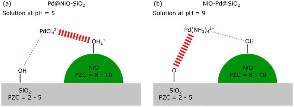 | ||
| Scheme 1 Schematic representation of the electrostatically driven selective adsorption of PdCl42− on NiO at pH = 5 (a) or Pd(NH3)42+ on SiO2 at pH = 9 (b). | ||
Catalyst characterization
High-angle annular dark-field scanning transmission electron microscopy (HAADF-STEM) images were taken on the TU/e CryoTitan (Thermo Fisher Scientific) with an acceleration voltage of 300 kV at room temperature. HAADF-STEM samples were prepared by grinding and suspending the catalyst in ethanol and drop-casting the suspension on a TEM grid. In addition, XRD measurements were carried on a Bruker Phaser D2 diffractometer using Cu Kα radiation. Furthermore, TPR was measured in a Micromeritics Autochem II 2920 equipped with a U-tube fixed bed reactor. In a typical experiment, ∼100 mg of sample was dried at 110 °C for three hours under He. H2-TPR was carried out in 4% H2 in N2 with a flow of 50 ml min−1 and a rate of 5 °C min−1 between 50 and 900 °C.H2 adsorption was measured using a Micromeritics ASAP 2020. In a typical experiment, ∼100 mg of sample was dried at 110 °C for 2 h in a He flow and then for 1 h under vacuum at that temperature. The H2 adsorption curves were measured at 35 °C. Reduced samples were exposed to an H2 flow at the indicated temperature for 3 h, evacuated at the same temperature as reduction, and the adsorption curves were measured. The amount of adsorbed H2 was determined by a linearized form of the Langmuir isotherm for dissociative adsorption.29 ICP-OES measurements were done on an AMETEK Spectroblue ICP apparatus. The samples were dissolved in an acid mixture of HF:HNO3:H2O (1:1:1 by volume) and then diluted with water.
IR spectroscopy was carried out on a Bruker Vertex 70v with a resolution of 2 cm−1 in the 4000–900 cm−1 range. Each spectrum was collected by averaging 32 scans. IR spectra were recorded using an environmental stainless-steel cell with CaF2 windows and a DTGS detector. The sample was pressed as a pellet with a diameter of 13 mm and a pellet density of ca. 5 mg/1.3 cm2. The pellet was pre-treated in situ at different reduction temperatures for 3 h in a flow of 10 vol% H2 in nitrogen. CO dosing was done while the sample was cooled to a temperature of −170 °C. The dosing of CO was done using a gas loop of 25 μL connected to a six-way valve. Reference measurements of blank SiO2 and the CO gas phase were acquired and subtracted from the spectra. A detailed description of the processing procedure can be found in the ESI,† extended method S1.
Quasi-in situ XPS measurements were carried out on a Kratos AXIS Ultra system with an Al Kα monochromatic source (15 kV, 10 mA). XPS spectra were recorded at a pass energy of 40 eV (step size 0.1 eV), and survey spectra at a pass energy of 160 eV (step size 0.5 eV). Samples were pre-treated in an attached vacuum chamber under an atmosphere of 10 vol% H2 in Ar at a total pressure of 1 bar. After the reaction, the chamber was evacuated, followed by transfer of the sample to the analysis chamber without exposure to air. The Si 2p peak was used as a charge reference at 103.5 eV for energy calibration, as the carbon signal disappeared after reduction at elevated temperatures.
Catalytic activity
The hydrogenation of cinnamaldehyde was carried out in stainless-steel batch reactors with a volume of 11 ml. The reactor was charged with 2.8 ml isopropyl alcohol (Merck Life Science, 99.5%) and 1.2 ml cinnamaldehyde (Merck Life Science, 99%). The reactors were pressurized with H2 to a pressure of 30 bar. The hydrogenation reaction was performed for 10 h at 50 °C by placing the autoclaves in a heating jacket. Before reaction, the catalysts were pre-treated in a flow reactor in a flow of 10 vol% H2 in He at a temperature ranging from 50–600 °C for 3 h (rate 5 °C min−1), followed by passivation in 1 vol% O2 in He. After reaction, the liquid phase was collected and analyzed by GC (Shimadzu GC-17A, Rxi-5-ms, FID, internal standard n-dodecane). The conversion was calculated on a carbon basis with all carbon accounted for. All reactions were carried out in triplo.Results
Strong electrostatic adsorption (SEA) was used to selectively deposit Pd on NiO particles dispersed on SiO2. The principle of SEA is based on electrostatic interactions between oppositely charged metal solute complexes and a charged support, as outlined by Regalbuto.30 To achieve selective SEA on one metal oxide over another, the point of zero (PZC) charges of the two metal oxides must be sufficiently different.19 In the present study, we aim to deposit Pd on either NiO crystallites supported on SiO2 or, as a reference, SiO2 in the presence of NiO particles. The PZC of NiO (PZC = 8–10 (ref. 31)) is different from the one of SiO2 (PZC = 2–5 (ref. 31)). Choosing a pH of the Pd-containing solution between these two pH values leads to positively charged –OH2+ groups at the NiO surface. At the same time, the silica surface is mainly terminated by neutral OH groups or negatively charged Si–O− groups. The PZC of SiO2 is around 2 with appreciable negative surface charge only developing above a pH of 6.32 Using a negatively charged PdCl42− precursor complex, we can preferentially deposit Pd on the Ni–OH2+ groups. We carried out such SEA with PdCl42− at a pH of 5 using NiO–SiO2 precursors containing NiO crystallites with average sizes of 3 nm and 50 nm (denoted by NiO(3)–SiO2 and NiO(50)–SiO2, respectively). The corresponding Pd-loaded samples are denoted by Pd@NiO(3)–SiO2 and Pd@NiO(50)–SiO2, respectively. Alternatively, by employing a positively charged Pd complex, Pd(NH3)42+, we deposited the Pd selectively on SiO2 at a relatively high pH. For this purpose, we set the pH to 9 to limit the dissolution of SiO2 and NiO. SiO2 dissolution would entail the risk of forming Ni-phyllosilicates, which are hard to reduce.33 These samples are denoted by NiO(3)–Pd@SiO2 and NiO(50)–Pd@SiO2 for small and large NiO crystallites, respectively.ICP elemental analysis is used to determine the obtained Pd loading, while the location of Pd concerning NiO and SiO2 is established with HAADF-STEM. We prepared two additional reference samples, namely Pd@SiO2-SEA(5), where PdCl42− is deposited on bare SiO2 at pH 5, while Pd@SiO2-SEA(9) is obtained using Pd(NH3)42+ at pH 9 (Table 1). The interaction of PdCl42− with SiO2 at pH 5 does not result in the deposition of Pd, as evident from the Pd content below the detection limit (ICP elemental analysis). When the same deposition approach is carried out with NiO(3)–SiO2, we obtain a Pd loading of 0.5 wt% (Pd@NiO(3)–SiO2). From this difference, we infer that Pd selectively interacts with NiO in the NiO(3)–SiO2 sample. For the reference deposition carried out with Pd(NH3)42+ at pH 9 (Pd@SiO2-SEA(9)), we obtain a Pd loading of 0.51 wt%. This confirms the successful deposition of the cationic Pd precursor on the negatively charged SiO2 surface. The Pd content is much lower than the one corresponding to a monolayer Pd coverage based on the silanol density (determined thermogravimetrically) and the surface area (∼6 wt% Pd).
| Sample | Ni wt% | Pd wt% | Reduction temperature (°C) | Particle size NiO (nm) | Particle size PdO (nm) |
|---|---|---|---|---|---|
| Particle sizes marked with “—” could not be determined.a Values below the detection limit. | |||||
| Pd@NiO(3)–SiO2 | 8.82 | 0.50 | 100 | 2.3 ± 0.7 | — |
| 600 | 3.1 ± 0.7 | — | |||
| Pd@NiO(50)–SiO2 | 17.0 | 0.82 | 100 | 50 ± 19 | 2.6 ± 0.5 |
| 600 | 13 ± 5 | — | |||
| NiO(3)–Pd@SiO2 | 9.10 | 1.31 | 100 | 1.9 ± 0.7 | — |
| 600 | 2.1 ± 0.5 | — | |||
| NiO(50)–Pd@SiO2 | 17.6 | 1.16 | 100 | 29 ± 16 | 1.5 ± 0.3 |
| 600 | 17 ± 6 | 1.7 ± 0.3 | |||
| Pd@SiO2-SEA(5) | n.d.a | n.d.a | 100 | — | — |
| Pd@SiO2-SEA(9) | n.d.a | 0.51 | 100 | — | 1.5 ± 0.3 |
| NiO(3)–SiO2 | 8.87 | n.d.a | 100 | 2.5 ± 0.7 | — |
Representative HAADF-STEM images of several Pd–NiO samples are shown in Fig. 1. The HAADF-STEM images of Pd@NiO(3)–SiO2 and NiO(3)–SiO2 reduced at 100 °C do not allow clear discrimination between Pd and Ni particles due to the very small particle size. EDX measurements on a probe-corrected STEM instrument at atomic resolution were therefore attempted. These attempts were unsuccessful due to the beam sensitivity of the SiO2 support, leading to strong sample drift during EDX mapping and spot analysis (see Fig. S1 in the ESI†).
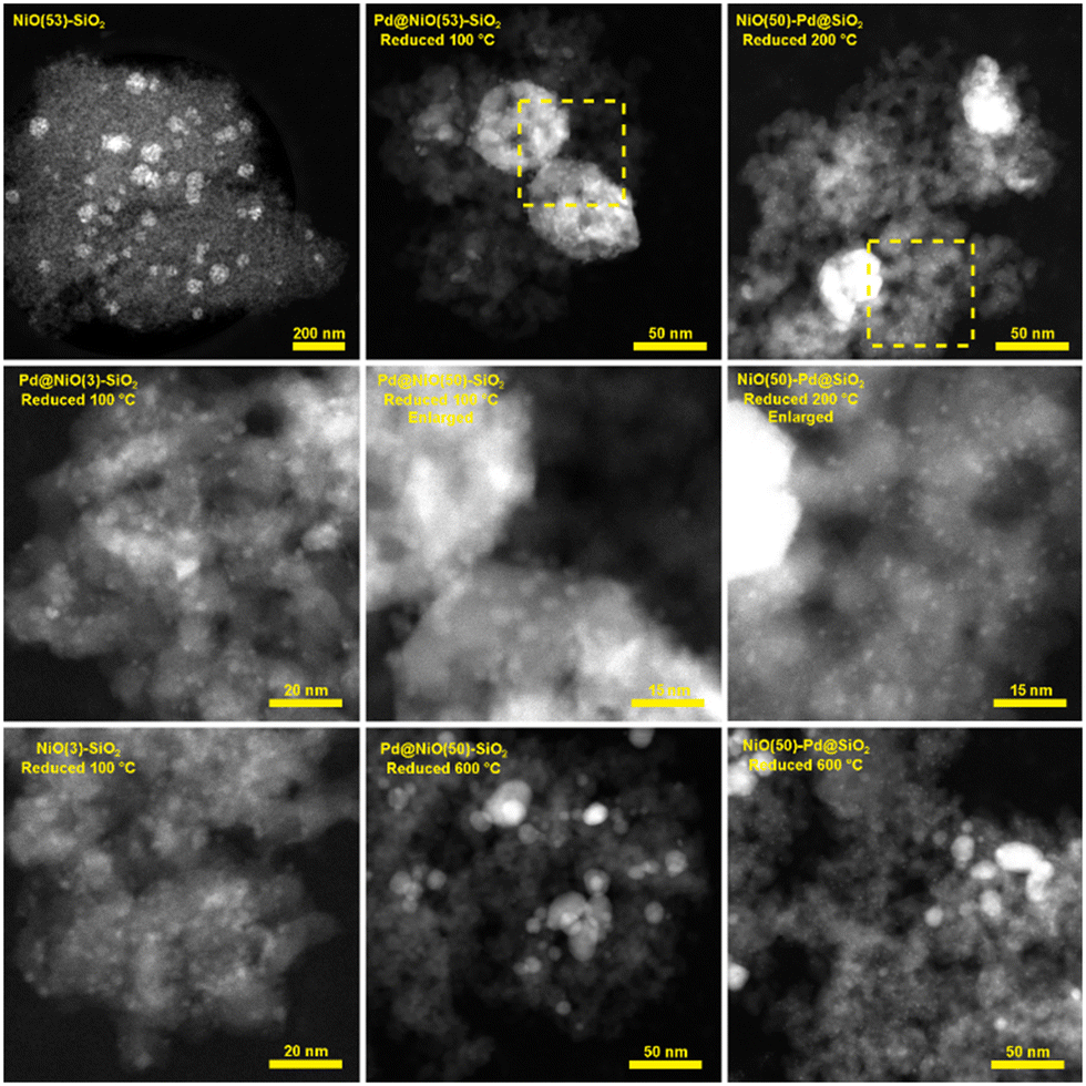 | ||
| Fig. 1 HAADF-STEM images of Pd–NiO–SiO2 catalysts prepared by SEA and reduced at different reduction temperatures. The dotted areas are enlarged to show more clearly that Pd particles were primarily deposited on either the NiO or the SiO2. Particle size distributions are given in the ESI,† Fig. S2. | ||
Alternatively, by using NiO(50)–SiO2 containing substantially larger NiO particles, we could readily determine the location of Pd when deposited on NiO. A comparison of the images of Pd@NiO(50)–SiO2 and NiO(50)–SiO2 reduced at 100 °C clearly shows that small Pd nanoparticles of roughly 2 nm in size are located on the large NiO particles. Inspection of STEM images of NiO(50)–Pd@SiO2 reduced at 100 °C show that Pd nanoparticles are primarily deposited on the silica support instead of NiO. As we will show below, the Ni particles remain in the oxidic state upon reduction at 100 °C. We also reduced NiO(50)–Pd@SiO2 at 600 °C to probe the changes upon NiO reduction. This does not significantly change the size of the Pd particles on the SiO2 support, while there are drastic changes in the Ni particle size due to its reduction to the metallic state. When the Pd@NiO(50)–SiO2 sample is reduced at 600 °C, it is impossible to observe the individual Pd nanoparticles on the larger Ni phase anymore, which may hint at the formation of Pd–Ni alloy.
X-ray diffractograms of these samples shown in Fig. 2 do not contain diffraction lines of Pd or PdO, which is in line with the high dispersion of Pd, as evidenced by STEM. Expectedly, the X-ray diffractograms of Pd@NiO(50)–SiO2 and NiO(50)–Pd@SiO2 contain sharp diffraction peaks of Ni phases (NiO in the precursor, Ni metal in the high-temperature reduced and passivated samples), which are less intense and much broader in the samples based on NiO(3)–SiO2. In the latter samples, air exposure during the transfer of the relatively small reduced Ni crystallites leads to complete oxidation to NiO. The metallic Ni diffraction lines did not change for the Pd-containing samples. Even if Pd–Ni alloy is formed, significant shifts are not expected that the high Ni/Pd ratio of 32.
 | ||
| Fig. 2 XRD patterns of Pd–NiO–SiO2 catalysts prepared by SEA: (a) NiO(50)–SiO2 and Pd-containing samples derived thereof reduced at 100 °C and 600 °C and (b) Pd@NiO(3)–SiO2 reduced at 100 °C and 600 °C. | ||
We evaluated the performance of the Pd–NiO–SiO2 catalysts in cinnamaldehyde hydrogenation upon reduction at different temperatures. The cinnamaldehyde conversion after 10 h reaction is shown as a function of the reduction temperature in Fig. 3. The corresponding product distributions are given in Fig. S3.† Hydrocinnamaldehyde is the main reaction product with a typical selectivity above 80% for all samples. Hydrocinnamyl alcohol is the other product observed in reasonable amounts. Only a small amount of cinnamyl alcohol (0–2%) is observed for some catalysts. There are no significant differences or trends in the product distribution among the samples. Literature mentions a shift in the products of hydrogenation towards hydrocinnamyl alcohol and cinnamyl alcohol when the Pd particles become larger than 3 nm.26–28 Thus, the catalytic hydrogenation results support the finding that the Pd particle size in our catalysts are smaller than ∼3 nm.
 | ||
| Fig. 3 Cinnamaldehyde hydrogenation activity of Pd–NiO–SiO2 catalysts prepared by SEA (batch reactor, 50 °C, 4 mg catalyst, 2.8 ml IPA solvent, 1.2 ml cinnamaldehyde, 30 bar H2, 10 h reaction time). | ||
The conversion as a function of the reduction temperature in Fig. 3 varies significantly among the catalysts. Most pronounced is the very different trend observed for the Pd@NiO–SiO2 and NiO–Pd@SiO2 catalysts. The monometallic Ni sample does not show appreciable catalytic activity, irrespective of the reduction temperature (Fig. S4†), which implies that the hydrogenation activity mainly stems from reduced Pd. Both Pd@NiO(3)–SiO2 and Pd@NiO(50)–SiO2 show a high cinnamaldehyde conversion at low reduction temperature, which declines when the reduction temperature is raised to 200 °C and beyond. The NiO(3)–Pd@SiO2 and NiO(50)–Pd@SiO2 samples exhibit the opposite trend with low activity after reduction at 50 °C and an increasing cinnamaldehyde conversion with increasing reduction temperature, which levels off upon reduction above 200 °C. Given the significant differences in Pd and Ni content between the catalysts containing small and large NiO particles, it can be stated that the performance does not strongly depend on the NiO particle size. As such, this strongly indicates that the catalytic activity stems from reduced Pd phases, as can be expected from the literature on this topic.34,35 Thus, in the remainder of this work, we will focus on resolving the nature of the different behavior of Pd when located on NiO or SiO2.
The H2-TPR trace of NiO(3)–SiO2 shown in Fig. 4 contains a broad reduction feature starting at 300 °C with a main contribution a 500 °C. Mile et al.36 assign the low-temperature shoulder to NiO particles weakly interacting with the SiO2 support. The main reduction feature at 500 °C can be assigned to smaller NiO nanoparticles or particles inside smaller pores, requiring a higher temperature to reduce. The trace of Pd@SiO2-SEA(9) contains only one reduction peak at 125 °C, which is due to the reduction of PdO to Pd. The profile of Pd@NiO(3)–SiO2 shows two distinct reduction features at 300 °C and 425 °C. As the Pd/Ni ratio in these samples is very low, most of the H2 consumed is due to NiO reduction, which is promoted by metallic Pd due to hydrogen spillover.15,16 The trace of NiO(3)–Pd@SiO2 can be interpreted as a combination of the traces of Pd@SiO2-SEA(9) and Pd@NiO(3)–SiO2. The low-temperature feature is due to the reduction of PdO on SiO2, while NiO reduction proceeds at higher temperatures. Despite the presence of two reduction features, Pd still affects the reduction of NiO, as can be appreciated from a comparison of the traces of NiO(3)–SiO2 and NiO(3)–Pd@SiO2. NiO in NiO(3)–Pd@SiO2 reduces at a lower temperature, similar to Pd@NiO(3)–SiO2. This shows that Pd promotes the reduction in these samples. We can also see that the shoulder is shifted to higher temperatures for NiO(3)–Pd@SiO2, showing there is less NiO interaction with Pd than in Pd@NiO(3)–SiO2.
 | ||
| Fig. 4 H2-TPR of Pd@NiO(3)–SiO2, NiO(3)–SiO2, Pd@SiO2-SEA(9) and NiO(3)–Pd@SiO2. 5 °C min−1, 4% H2 in N2, 50 ml min−1. | ||
We then studied the surface of these catalysts after reduction at different temperatures by quasi-in situ XPS. We first discuss the Pd 3d and Ni 2p spectra of the monometallic reference catalysts. Details of the models used for fitting these spectra can be found in the ESI† (extended method section S2). Fig. 5 shows the Pd 3d spectra of Pd@SiO2-SEA(9). After drying, Pd is present as Pd2+ in PdO, as can be judged from the Pd 3d5/2 binding energy of 337.1 eV.37 Upon reduction at 50 °C, a second Pd 3d5/2 feature at 335.2 eV can be assigned to metallic Pd.38 The spectra of the samples reduced at 100 °C and above only contain the metallic Pd component. This is in reasonable agreement with the TPR data in Fig. 4. The observation that Pd is already reduced completely at 100 °C during quasi-in situ XPS is likely due to the dwell time of 3 h employed at each reduction temperature. In contrast, the TPR data was obtained at a heating rate of 5 °C min−1. Moreover, we cannot exclude analysis-induced reduction of PdO.39,40 The Ni 2p XPS spectra for NiO(3)–SiO2 are shown in Fig. S5.† The dried sample and the sample reduced at 200 °C contain only Ni2+. After reduction at 300 °C and 400 °C, an additional feature due to metallic Ni with a 2p3/2 binding energy of 852.5 eV can be seen. Reduction at 600 °C results in the complete reduction of Ni.
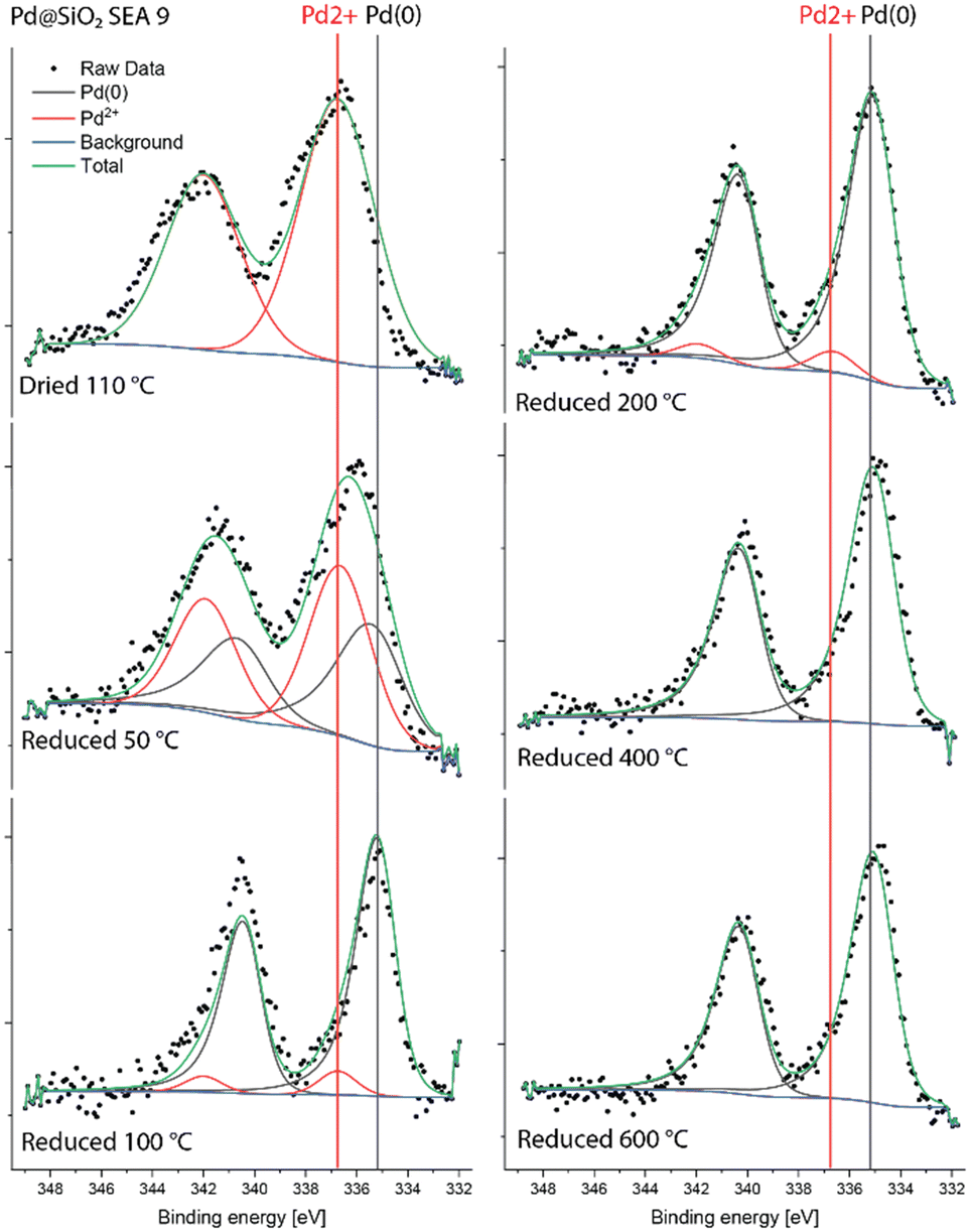 | ||
| Fig. 5 Quasi-in situ Pd 3d XPS spectra of Pd@SiO2-SEA(9) measured after different reduction treatments. | ||
The Pd 3d XPS spectra of Pd@NiO(3)–SiO2 and NiO(3)–Pd@SiO2 are shown in Fig. 6 and 7. The XPS spectra of NiO(3)–Pd@SiO2 evolve in a comparable manner with temperature as those already discussed for Pd@SiO2. While PdO is the dominant phase in the dried state, reduction at 100 °C already completely converts Pd2+ to metallic Pd. However, Pd in Pd@NiO(3)–SiO2 is already fully reduced in the dried state. This result, verified in a duplo measurement, shows that the PdO phase in contact with NiO is much more prone to reduction by X-ray exposure in the XPS apparatus. As such, this hints at a weaker interaction of Pd with NiO than with SiO2, resulting in higher reducibility of Ni in Pd@NiO(3)–SiO2. Interestingly, the Ni 2p spectra for these bimetallic catalysts were very similar to those for the NiO(3)–SiO2 reference (Fig. S6 and S7†), indicating a very small promoting role of Pd on NiO reduction. These results seem to contrast the H2-TPR measurements, which showed a promoting effect of Pd on NiO reduction. To investigate this difference obtained by XPS and H2-TPR, we carried out additional H2-TPR measurements using the same heating rate and dwells as employed in the XPS measurements. The corresponding H2-TPR results are shown in Fig. S8,† while the H2-TPR and XPS results obtained in this way are collected in Fig. 8. Clearly, the differences mentioned above are due to the dwells introduced in the heating profile.
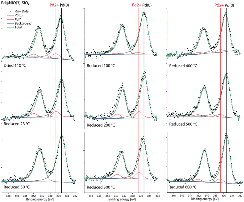 | ||
| Fig. 6 Quasi-in situ Pd 3d XPS spectra of Pd@NiO(3)–SiO2 measured after different reduction treatments. | ||
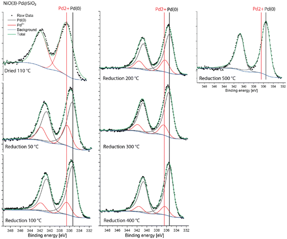 | ||
| Fig. 7 Quasi-in situ Pd 3d XPS spectra of NiO(3)–Pd@SiO2 measured after different reduction treatments. | ||
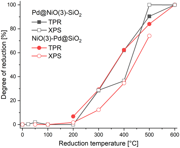 | ||
| Fig. 8 Comparison between reduction degree of Ni obtained from H2-TPR and XPS measurements carried out using stepwise heating and dwells for 3 h at the indicated temperatures. | ||
CO IR spectra measured for Pd@NiO(3)–SiO2 and NiO(3)–Pd@SiO2 at different reduction temperatures are shown in Fig. 9. Preliminary results showed that PdO can be easily reduced to Pd metal when exposed to CO at ambient conditions (Fig. S10†) in line with results for Pd/CeO2.41 Therefore, we recorded the CO IR spectra at liquid N2 temperature (∼−170 °C). The contributions of gas-phase CO and the bare SiO2 support were removed from the IR spectra (see ESI† extended methods section S2 and Fig. S10–S12†).
 | ||
| Fig. 9 CO IR spectra following drying or reduction at varying temperatures. The spectra were recorded at a CO pressure of 0.24 mbar in the cell, while the sample temperature is approximately −170 °C. | ||
In the dried state, the IR spectra of Pd@NiO(3)–SiO2 and NiO(3)–Pd@SiO2 (Fig. 9) contain a single feature at 2165–2170 cm−1, which can be assigned to CO adsorbed on Ni2+ in NiO according to Hadjiivanov et al.42 While this signal first decreases in intensity after reduction at 50 °C, it is stronger again after reduction at 200 °C, followed by a decrease upon reduction at 400 °C. The decrease after reduction at 400 °C can be attributed to the reduction of NiO to Ni, as followed from H2-TPR and XPS. The decrease in signal after low-temperature reduction is an artifact of how the CO IR spectra were obtained. The spectra were obtained following successive treatments on the same sample. First, the sample was dried, followed by evacuation and cooling to liquid N2 temperature. At a temperature of ∼−170 °C, IR spectra were recorded for samples. Then the samples were evacuated and heated back to room temperature, followed by reduction at 50 °C for 3 h. IR spectra were then recorded in the same manner involving evacuation, cooling, and CO exposure. After this treatment, additional bands are observed at 1555 cm−1, 1410 cm−1 (and 1707 cm−1 for NiO(3)–Pd@SiO2) together with the disappearance of the NiO signal at 2170 cm−1 (Fig. S13†). The signals at 1555 cm−1 and 1410 cm−1 indicate that carbonates have formed. These carbonates form when the sample is heated to room temperature after the first measurement by residual CO left on the sample. These carbonates partially cover the NiO, resulting in a lower intensity of the relevant IR bands. A temperature of 200 °C or higher is required to remove these carbonates. When these carbonates are removed the underlying NiO becomes visible again and the signal intensity of the corresponding bands increase.
Reducing the Pd@NiO(3)–SiO2 sample at 50 °C leads to IR bands due to linear and bridged CO on metallic Pd at 2098 cm−1 and 1949 cm−1, respectively. These bands become more pronounced after reduction at 100 and 200 °C due to the further reduction of Pd. The observation of a larger relative contribution of bridged CO species at 200 °C points to the growth of the Pd particles during temperature-programmed reduction. In contrast, when the NiO(3)–Pd@SiO2 is reduced at 50 °C, the CO IR spectrum does not contain IR features of reduced Pd. Bands due to metallic Pd are only observed after reduction at 100 °C. These differences demonstrate that Pd on NiO in Pd@NiO(3)–SiO2 can be reduced easier than Pd on SiO2 in NiO(3)–Pd@SiO2.
Reduction to 400 °C results in the reduction of NiO to Ni, as evident from CO adsorption on metallic Ni sites in both catalysts. Linear and bridged CO adsorption bands are observed at 2098 cm−1 and 1949 cm−1, respectively. There is also an IR band at 2054 cm−1. All these CO IR bands were also reported for reduced Ni/SiO2 by Mihaylov et al.43 These authors ascribed a band at 2046 cm−1 to Ni(CO)4. The Ni(CO)4 is likely physiosorbed on the surface due to the low measurement temperature.44 The spectrum of the monometallic Ni–SiO2 sample reduced at 400 °C displays similar bands at 2098 cm−1, 2054 cm−1 and 1949 cm−1 (Fig. S14†).
Besides the onset of Pd reduction, the CO IR spectra of Pd@NiO(3)–SiO2 and NiO(3)–Pd@SiO2 also reveal other differences. The shoulder at 2054 cm−1 observed for Pd@NiO(3)–SiO2 reduced at 200 °C is not present for NiO(3)–Pd@SiO2. This shoulder develops into a resolved band for the former catalyst after reduction at 400 °C. This feature is also present in the IR spectrum of NiO(3)–Pd@SiO2 after reduction at 400 °C. The peak at 2054 cm−1 is a clear signal of CO bound to metallic Ni. It is also observed in IR spectra obtained after reduction of the Ni–SiO2 reference at 400 °C (Fig. S14†). The appearance of this band after reduction at a lower temperature for Pd@NiO(3)–SiO2 in comparison to NiO(3)–Pd@SiO2 shows the proximity of Pd to NiO in the former catalyst with spillover hydrogen from Pd lowering the onset temperature of NiO reduction.
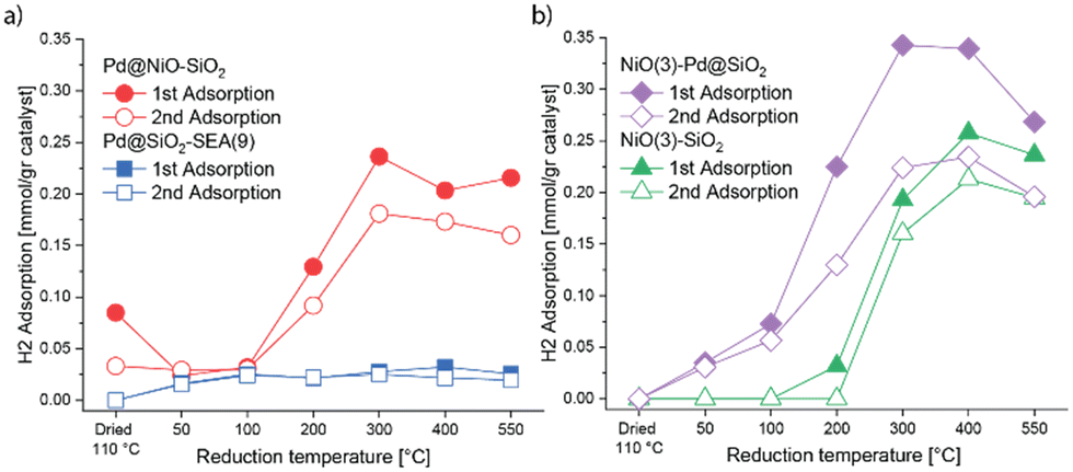
H2 chemisorption was employed to estimate the number of metallic sites obtained after reduction at different temperatures. Metallic Pd and Ni surface sites can contribute to chemisorption of H2 at 35 °C.45 The results for the various catalysts are displayed in Fig. 10, while the corresponding numerical data are provided in Table S1.† The absence of chemisorbed H2 for dried Pd@SiO2-SEA(9) shows that PdO is not reduced. Reduction at temperatures in the 100–550 °C range results in appreciable H2 chemisorption, which is nearly independent of temperature. The H/Pd ratios between 0.9 and 1.0 indicate the very high dispersion of Pd. Such H/Pd ratios correspond to a Pd particle size of ca. 1 nm, which is in reasonable agreement with the particle size of 1.4 nm determined by HAADF-STEM. The H/Pd ratio after reduction at 50 °C is slightly lower, most likely due to the incomplete reduction of Pd. The monometallic NiO(3)–SiO2 does not chemisorb H2 after drying or reduction at temperatures up to 200 °C. This agrees with the H2-TPR results, which showed that NiO only starts to reduce at 300 °C. There is a small irreversible uptake of H2 after reduction at 200 °C, which may hint at a small amount of reduced Ni strongly adsorbing H2. After reduction at 300 °C, a large amount of H2 is adsorbed, pointing to significant reduction of NiO to Ni. Reduction at 400 °C results in a much larger amount of adsorbed H2. After treatment at 550 °C, the amount of chemisorbed H2 is lower than at 400 °C, which can be explained by the sintering of the Ni nanoparticles.
 | ||
| Fig. 10 H2 chemisorption of Pd–NiO catalysts after different reduction treatments (first point represented dried catalyst): (a) Pd@NiO–SiO2 and Pd@SiO2-SEA(9) and (b) NiO(3)–Pd@SiO2 and NiO(3)–SiO2. | ||
The trends in the H/Pd and H/Ni ratios for NiO(3)–Pd@SiO2 can be interpreted as a combination of the trends for Pd@SiO2 and NiO(3)–SiO2. No H2 is adsorbed after drying at 110 °C. Reduction at 50 °C and 100 °C shows increasing amounts of chemisorbed H2, which is due to reduction of PdO to Pd, as also observed for Pd@SiO2-EA(9). Reduction at 200 °C increases the amount of reversible and irreversible adsorbed H2, which means that metallic Ni sites form due to the reduction of NiO. The irreversible fraction is likely due to H2 chemisorbing on metallic Ni sites, as also observed for NiO(3)–SiO2. The amount of chemisorbed H2 exhibits a maximum at a reduction temperature of 300 °C. The value upon reduction at 400 °C is nearly the same. This implies that all Pd and Ni have been reduced at these temperatures. As observed for the pure NiO(3)–SiO2 sample, reduction at 550 °C leads to a decrease in the amount of adsorbed H2, indicative of Ni sintering.
Unlike the other dried catalysts, Pd@NiO(3)–SiO2 already shows H2 uptake after drying. The first uptake of 0.085 mmol gcat−1 is substantially larger than the second uptake of 0.033 mmol gcat−1. This amount of irreversibly adsorbed H2 of 0.052 mmol gcat−1 is comparable to that of Pd present (0.047 mmol gcat−1 based on the Pd loading of 0.50 wt% as determined by ICP). Thus, it is reasonable to conclude that the chemisorbed H2 has been consumed to reduce PdO to Pd. This is in line with the higher reducibility of PdO on NiO compared to PdO on SiO2. This also implies that the second lower uptake is due to the absence of PdO reduction, as it has already been converted to Pd. Differently, when Pd@NiO(3)–SiO2 is reduced at 50 °C and 100 °C, the amounts of chemisorbed H2 during the first and second uptake are comparable, implying that no further reduction occurred. The H/Pd ratios based on reversible H2 chemisorption upon reduction at 50 °C and 100 °C are in the range of 1.0–1.4. These ratios are higher than those observed for reduced Pd@SiO2-SEA(9) (0.7 and 1.1, respectively). This means that the Pd particle size in Pd@NiO(3)–SiO2 is likely in the subnanometer range, and its Pd dispersion is higher than Pd on silica in Pd@SiO2-SEA(9) at equal Pd loading. Upon reduction at 200 °C, the amount of adsorbed H2 increased as NiO reduced to Ni. After reduction at 300 °C and 400 °C, the adsorbed amount of H2 does not change. Therefore, NiO is likely completely reduced already at 300 °C. The amount of adsorbed H2 decreases slightly after reduction at 550 °C, which can be ascribed to sintering.
General discussion
Our data show that metallic Pd displays a much higher activity than Ni in the hydrogenation of cinnamaldehyde in line with the literature.26 When Pd particles are located on SiO2, reduction at low temperatures is incomplete, explaining the increasing cinnamaldehyde conversion with temperature. This goes together with some sintering of Pd. By selectively placing the Pd precursor complex on NiO in Pd@NiO(3)–SiO2, Pd reduction becomes more facile. Already after exposure to H2 at 35 °C, metallic Pd is formed on NiO, which exhibits a substantially higher activity in cinnamaldehyde hydrogenation than Pd on SiO2. The activity of Pd@NiO(3)–SiO2 reduced at low temperature is higher than the activity of very small Pd particles prepared by SEA on SiO2 (Pd–SiO2-SEA(9)). From this, we infer that low-temperature reduction of Pd@NiO(3)–SiO2 results in small metallic Pd clusters with a high activity in cinnamaldehyde hydrogenation, which is comparable to the activity of Pd@SiO2-SEA(9) after reduction at higher temperatures. The product distribution of cinnamaldehyde hydrogenation of these samples is very similar, indicating that the same type of Pd surface site is involved. The composition of the product mixtures indicates the formation of Pd particles smaller than 3 nm, which aligns with the characterization data. The higher activity of the NiO-supported Pd phase can therefore be reasonably attributed to the low temperature at which PdO can be reduced to Pd metal. Reduction at low temperatures is beneficial, as sintering of reduced Pd atoms is suppressed. Reducing Pd@NiO(3)–SiO2 at temperatures above 200 °C decreases the catalytic activity, which coincides with the onset of NiO reduction to Ni. Therefore, the decreasing activity with increasing reduction temperature can be attributed to the formation of PdNi alloy, although further sintering of Pd can also play a role.Conclusions
A substrate-specific SEA method was used to selectively place Pd on either NiO or SiO2 of a NiO–SiO2 catalyst prepared by IWI. Unlike Pd/SiO2, which requires high-temperature reduction to achieve high activity in cinnamaldehyde hydrogenation, PdO placed on NiO could be reduced close to room temperature, achieving a better Pd dispersion and a significantly higher activity than Pd–SiO2. Quasi-in situ XPS and CO IR spectroscopy showed the much easier reduction of PdO supported on NiO than PdO supported on SiO2. The conversion of PdO to Pd at lower temperatures results in a higher Pd dispersion as confirmed by H2-chemisorption measurements. Reducing the Pd@NiO–SiO2 catalyst at a too high temperature led to a strong decrease of the activity due to formation of PdNi alloy.Data availability
The data supporting this article have been included as part of the ESI.†Author contributions
RP conceptualized the experiments, synthesized, characterized, and tested the catalysts. EH and HF supervised the project. All authors discussed the results and contributed to the final manuscript.Conflicts of interest
There are no conflicts to declare.Acknowledgements
We would like to acknowledge the Advanced Research Center Chemical Building Blocks Consortium (ARC-CBBC) for funding. ARC-CBBC is co-founded by the Netherlands Organization for Scientific Research (NWO) and the Netherlands Ministry of Economic Affairs.Notes and references
- H. U. Blaser, C. Malan, B. Pugin, F. Spindler, H. Steiner and M. Studer, Adv. Synth. Catal., 2003, 345, 103–151 CrossRef CAS.
- S. De, J. Zhang, R. Luque and N. Yan, Energy Environ. Sci., 2016, 9, 3314–3347 RSC.
- Y. Nakagawa and K. Tomishige, Catal. Commun., 2010, 12, 154–156 CrossRef CAS.
- Y. Nakagawa, M. Tamura and K. Tomishige, J. Jpn. Pet. Inst., 2017, 60, 1–9 CrossRef CAS.
- J. C. Bertolini, P. Miegge, P. Hermann, J. L. Rousset and B. Tardy, Surf. Sci., 1995, 31–333, 651–658 CrossRef.
- A. C. Michel, L. Lianos, J. L. Rousset, P. Delichère, N. S. Prakash, J. Massardier, Y. Jugnet and J. C. Bertolini, Surf. Sci., 1998, 416, 288–294 CrossRef CAS.
- P. Miegge, J. L. Rousset, B. Tardy, J. Massardier and J. C. Bertolini, J. Catal., 1994, 149, 404–413 CrossRef CAS.
- P. Hermann, B. Tardy, D. Simon, J. M. Guigner, B. Bigot and J. C. Bertolini, Surf. Sci., 1994, 307–309, 422–427 CrossRef CAS.
- R. Massard, D. Uzio, C. Thomazeau, C. Pichon, J. L. Rousset and J. C. Bertolini, J. Catal., 2007, 245, 133–143 CrossRef CAS.
- S. Campisi, C. E. Chan-Thaw, L. E. Chinchilla, A. Chutia, G. A. Botton, K. M. H. Mohammed, N. Dimitratos, P. P. Wells and A. Villa, ACS Catal., 2020, 10, 5483–5492 CrossRef CAS.
- H. Liu, K. Tao, C. Xiong and S. Zhou, Catal. Sci. Technol., 2015, 5, 405–414 RSC.
- Y. Wang, X. Cui, Y. Deng and F. Shi, RSC Adv., 2014, 4, 2729–2732 RSC.
- Q. Meng, J. Liu, X. Weng, P. Sun, J. A. Darr and Z. Wu, Catal. Sci. Technol., 2018, 8, 1858–1866 RSC.
- A. Parastaev, V. Muravev, E. H. Osta, T. F. Kimpel, J. F. M. Simons, A. J. F. van Hoof, E. Uslamin, L. Zhang, J. J. C. Struijs, D. B. Burueva, E. V. Pokochueva, K. V. Kovtunov, I. V. Koptyug, I. J. Villar-Garcia, C. Escudero, T. Altantzis, P. Lui, A. Béché, S. Bals, N. Kosinov and E. J. M. Hensen, Nat. Catal., 2022, 5, 1051–1060 CrossRef CAS.
- A. Roman and B. Delmon, J. Catal., 1973, 30, 333–342 CrossRef CAS.
- E. J. Nowak and R. M. Koros, J. Catal., 1967, 7, 50–56 CrossRef CAS.
- E. J. Nowak, J. Phys. Chem., 1969, 73, 3790–3794 CrossRef CAS.
- R. Prins, Chem. Rev., 2012, 112, 2714–2738 CrossRef CAS.
- T. E. Feltes, L. Espinosa-Alonso, E. de Smit, L. D'Souza, R. J. Meyer, B. M. Weckhuysen and J. R. Regalbuto, J. Catal., 2010, 270, 95–102 CrossRef CAS.
- K. Konno, H. Sakagami, Y. Kawazoe and N. Yamamoto, US005632980A, 1997.
- Ullmann's Encyclopedia of Industrial Chemistry, 7th edn, 2014 Search PubMed.
- C. Mohr and P. Claus, Sci. Prog., 2001, 84, 311–334 CrossRef CAS.
- B. F. Machado, H. T. Gomes, P. Serp, P. Kalck and J. L. Faria, ChemCatChem, 2010, 2, 190–197 CrossRef CAS.
- Y. Li, H. Cheng, W. Lin, C. Zhang, Q. Wu, F. Zhao and M. Arai, Catal. Sci. Technol., 2018, 8, 3580–3589 RSC.
- L. Zhang, J. M. Winterbottom, A. P. Boyes and S. Raymahasay, J. Chem. Technol. Biotechnol., 1998, 72, 264–272 CrossRef CAS.
- F. Jiang, J. Cai, B. Liu, Y. Xu and X. Liu, RSC Adv., 2016, 6, 75541–75551 RSC.
- A. J. Plomp, H. Vuori, A. O. I. Krause, K. P. de Jong and J. H. Bitter, Appl. Catal., A, 2008, 351, 9–15 CrossRef CAS.
- A. Giroir-Fendler, D. Richard and P. Gallezot, Catal. Lett., 1990, 5, 175–181 CrossRef CAS.
- G. C. Bond and L. Hui, J. Catal., 1994, 147, 346–348 CrossRef CAS.
- J. Regalbuto, Catalyst Preparation: Science and Engineering, 2007 Search PubMed.
- M. Kosmulski, Adv. Colloid Interface Sci., 2016, 238, 1–61 CrossRef CAS.
- R. K. Iler, The Chemistry of Silica, Solubility, Polymerization, Colloid and Surface Properties, and Biochemistry, 1979 Search PubMed.
- P. Burattin, M. Che and C. Louis, J. Phys. Chem. B, 1997, 101, 7060–7074 CrossRef CAS.
- M. Lashdaf, A. O. I. Krause, M. Lindblad, M. Tiitta and T. Venäläinen, Appl. Catal., A, 2003, 241, 65–75 CrossRef CAS.
- C. Espro, A. Donato, S. Galvagno and G. Neri, React. Kinet., Mech. Catal., 2016, 118, 223–233 CrossRef CAS.
- B. Mile, D. Stirling, M. A. Zammitt, A. Lovell and M. Webb, J. Catal., 1988, 114, 217–229 CrossRef CAS.
- A. Tressaud, S. Khairoun, H. Touhara and N. Watanabe, Z. Anorg. Allg. Chem., 1986, 541, 291–299 CrossRef.
- K. Noack, H. Zbinden and R. Schlögl, Catal. Lett., 1990, 145–156 CrossRef CAS.
- T. Pillo, R. Zimmermann, P. Steiner and S. Hüfner, J. Phys.: Condens. Matter, 1997, 9, 3987–3999 CrossRef CAS.
- T. H. Fleisch, G. W. Zajac, J. O. Schreiner and G. J. Mains, Appl. Surf. Sci., 1986, 26, 488–497 CrossRef CAS.
- G. Spezzati, Y. Su, J. P. Hofmann, A. D. Benavidez, A. T. DeLaRiva, J. McCabe, A. K. Datye and E. J. M. Hensen, ACS Catal., 2017, 7, 6887–6891 CrossRef CAS.
- K. Hadjiivanov, M. Mihaylov, D. Klissurski, P. Stefanov, N. Abadjieva, E. Vassileva and L. Mintchev, J. Catal., 1999, 185, 314–323 CrossRef CAS.
- M. Mihaylov, K. Hadjiivanov and H. Knözinger, Catal. Lett., 2001, 76, 59–63 CrossRef CAS.
- K. Mohana Rao, G. Spoto and A. Zecchina, Langmuir, 1989, 319–325 Search PubMed.
- J. T. Richardson and T. S. Cale, J. Catal., 1986, 102, 419–432 CrossRef CAS.
Footnote |
| † Electronic supplementary information (ESI) available. See DOI: https://doi.org/10.1039/d4cy01190b |
| This journal is © The Royal Society of Chemistry 2025 |