
 Open Access Article
 This Open Access Article is licensed under a
 Creative Commons Attribution 3.0 Unported Licence
Influence of the supported ionic-liquid layer thickness on Z-selectivity in 1-alkyne hydrosilylation under continuous flow†
André
Böth
a,
Florian
Kaltwasser
a,
Christian
Priedigkeit
a,
Boshra
Atwi
b,
Wolfgang
Frey
c,
Michael R.
Buchmeiser
 *b and
Ulrich
Tallarek
*a
*b and
Ulrich
Tallarek
*a
aDepartment of Chemistry, Philipps-Universität Marburg, Hans-Meerwein-Strasse 4, D-35032 Marburg, Germany. E-mail: tallarek@staff.uni-marburg.de
bInstitute of Polymer Chemistry, Universität Stuttgart, Pfaffenwaldring 55, D-70569 Stuttgart, Germany. E-mail: michael.buchmeiser@ipoc.uni-stuttgart.de
cInstitute of Organic Chemistry, Universität Stuttgart, Pfaffenwaldring 55, D-70569 Stuttgart, Germany
First published on 28th May 2025
Abstract
1-Butyl-3-methylimidazolium tetrafluoroborate containing different rhodium(I) N-heterocyclic carbene (NHC) complexes was immobilized as a supported ionic-liquid phase (SILP) inside the mesopores of a silica monolith to study the impact of SILP thickness (dSILP) from the thin-SILP-limit (dSILP ≈ 1 nm) to complete mesopore filling (dSILP ≈ 15 nm) on Z/E-selectivity in the rhodium-catalyzed hydrosilylation of phenylacetylene with dimethylphenylsilane. A coupled analytical platform allowed monitoring of both yield and selectivity of the produced isomer pattern online in continuous-flow experiments of 600 minutes using methyl tert-butyl ether as mobile phase. The approach provided new insights into the mechanistic aspects of the reaction under liquid confinement conditions created by the varied SILP thickness. With decreasing dSILP, the selectivity of a Rh-catalyst based on a chelating NHC is shifted towards the β(Z)-isomer, climaxing in a boost of the Z/E-ratio for dSILP = 1 nm by a factor of >30, while the selectivity is mostly unaffected for catalysts based on nonchelating NHCs. The spatial dimension of 1 nm reflects the rigid part of the SILP characterized by a quasi-frozen morphology of the ionic liquid. It shapes a local, spatially as well as molecularly confined catalytic environment, which, together with a tailored catalyst, facilitates the predominant formation of the β(Z)-isomer under kinetic control. Contrariwise, the random, mobile part of the adjoining bulk SILP, emerging with increasing dSILP, generally favors the formation of the β(E)-isomer under thermodynamic control.
1. Introduction
The hydrosilylation of terminal alkynes is an important synthetic method for the preparation of vinylsilanes, which have a number of applications in organic synthesis1–5 and materials science,6 including the production of polymers7 and fine chemicals.8 By the addition of Si–H bonds to a terminal alkyne, the hydrosilylation reaction yields different vinylsilane isomers (Scheme 1). | ||
| Scheme 1 Hydrosilylation and dehydrogenative silylation of terminal alkynes. | ||
Accordingly, the reaction can proceed in an anti-Markovnikov mode, leading to the β(E)- and β(Z)-vinylsilane isomers, or in a Markovnikov mode to give the α-vinylsilane. For some catalysts, dehydrogenative silylation products (the silyl-alkyne derivative and the corresponding alkene) are received as by-products. Tailoring the synthesis towards an isomer is a challenging task, because the selectivity depends on a number of factors including the nature of the catalyst, the substrates, and the reaction conditions. Unsurprisingly, many catalysts have been designed with distinct electronic and steric properties to gain control over the regio- and stereoselectivity.9
Transition-metal N-heterocyclic carbene (NHC) complexes have received particular attention in recent years for alkyne hydrosilylation due to their versatility and wide range of applications.10–16 NHC–Ir(I), Rh(I), and Ru(I) catalysts demonstrate high anti-Markovnikov selectivity in the hydrosilylation of terminal alkynes, i.e., they mainly produce mixtures of β(E)- and β(Z)-isomers.10,17,18 Nevertheless, the isomerization of the thermodynamically labile β(Z)-isomer into the stable β(E)-vinylsilane remains an issue.19 Further, cationic rhodium complexes were found to be highly β(E)-selective,20,21 whereas, e.g., zwitterionic Rh(III) bis(NHC) complexes demonstrate excellent selectivity for the thermodynamically less stable β(Z)-isomer.22 Another strategy to control selectivity relies on the immobilization of the catalyst inside a confined space. Examples include Rh(I)/Rh(II) catalysts supported in mesoporous silica and rhodium nanoparticles in carbon reactors.23,24 Both studies report a change in selectivity with respect to the homogeneous conditions. It has been argued that the driving force originates in confinement effects, including preferred substrate orientation, increased local concentrations near active sites, the stabilization of intermediates, and enhanced steric congestion. Finally, Messerle and co-workers showed that Rh and Ir complexes covalently anchored to a carbon black-supported surface enable β(Z)-selectivity, depending on the metal center, ligand environment, and tether length.25,26 Their results suggest that subtle changes in surface coverage and linker architecture can alter the product distribution, offering a modular, heterobimetallic approach to selectivity control. In a complementary approach, Sánchez-Page et al.27 achieved high β(Z)-selectivity using cyclometalated Rh(III)–NHC complexes, both in solution and supported on graphene, through a metal–ligand cooperative mechanism.
An intriguing approach that has become popular in recent years involves a supported ionic-liquid phase (SILP),28–31 where the homogeneous catalyst is dissolved in an ionic liquid (IL) that is physically adsorbed as a film on a high-surface area solid support. By providing the substrates in the gas phase, the reaction mixture can be easily separated from the SILP without catalyst leaching, so that the approach lends itself for the adaptation in continuous-flow experiments.32–38 We extended this technology to supported ionic liquid–liquid phase conditions32,39–41 by using a substrate- and, in course of the reaction, also product-containing liquid phase that does not mix with the IL. In this way, the SILP concept was successfully extended to more complex, high-boiling substrates.
In comparison to batch operation, the utilization of compact continuous-flow microreactors enables the effective use of large surface-to-volume ratios, facilitating heat and mass transfer. This, in turn, impacts yield and selectivity as well as the practicable reaction time.42,43 However, literature illustrating how the SILP and the SILP thickness (dSILP), in particular, affect the selectivity of the dissolved catalyst in view of the spatial confinement engendered by the SILP is still very scarce.32,44 The aspect of the actual SILP thickness and catalyst condition is complemented by increased efforts in the rational design of task-specific ILs, which self-assemble on a surface (without covalent bonding) and offer a metal-binding site at a controlled distance from the solid support.45
The main objective of the current work was to understand the predominant formation of the β(Z)-isomer in the hydrosilylation of 1-alkynes catalyzed by SILP-embedded Rh–NHC catalysts, which otherwise predominantly produce the β(E)-isomer under homogeneous, that is, biphasic bulk IL-organic solvent conditions.32,44 For that purpose, we immobilized the IL 1-butyl-3-methylimidazolium tetrafluoroborate [BMIM][BF4] on the surface of a macro–mesoporous silica monolith, suitable for continuous-flow operation. The employed catalysts (Rh-1, Rh-2, Rh-3) and the IL are shown in Fig. 1.
 | ||
| Fig. 1 The Rh–NHC complexes [((1-(pyrid-2-yl)-3-mesityl)-imidazol-2-ylidene)(η4-1,5-cyclooctadiene) rhodium(I) tetrafluoroborate] (Rh-1), [(1,3-dimethylimidazol-2-ylidene)(η4-1,5-cyclooctadiene) rhodium(I) tetrafluoroborate] (Rh-2), and [(1,3-dimesityltetrahydropyrimdin-2-ylidene)(η4-1,5-cyclooctadiene) rhodium(I) chloride] (Rh-3), as well as the room-temperature IL 1-butyl-3-methylimidazolium tetrafluoroborate, [BMIM][BF4], used in this work. Mes = mesityl (2,4,6-trimethylphen-1-yl). | ||
To better understand the confinement effect engendered by the SILP, we investigated the influence of its thickness on the Z/E-selectivity in the hydrosilylation reaction between phenylacetylene (PA) and dimethylphenylsilane (DMPS) under biphasic, liquid–liquid, continuous-flow conditions on the monolithic column using methyl tert-butyl ether (MTBE) as liquid mobile phase that does not mix with the IL (Scheme 2). Continuous-flow operation was established with high-precision, high-pressure pumps connected to the SILP/catalyst-loaded column, and the real-time monitoring of the reaction was achieved by hyphenating the reactor (first) dimension online with a concentration analytics (second) dimension for chromatographic separation as well as detection and quantification of all compounds of interest.
 | ||
| Scheme 2 Biphasic, continuous-flow hydrosilylation between PA (1) and DMPS (2) with Rh-1 in the SILP formed by [BMIM][BF4] on a macro–mesoporous silica monolith. Stationary phase: solid silica and SILP (containing Rh-1), mobile phase: MTBE (containing reactants and products). | ||
The two-dimensional setup facilitated the automation of the entire sampling process and enabled us to repeatedly run experiments with varied dSILP over extended periods, typically for 600 minutes, during which the production of the targeted isomers, especially the Z/E-selectivity of the reaction, was continuously monitored. This would otherwise become very laborious as well as time-consuming with batch operation.
Data acquired with the monolithic microreactor for SILP thicknesses between 1 and 15 nm reveal that the Z/E-selectivity of the reaction is generally low at the beginning and for dSILP ≥ 3 nm also increases only moderately during the 600 minutes of the experiments. However, for dSILP = 1 nm the Z/E-selectivity demonstrates a real boost. These observations highlight that more attention should be paid to the morphology as well as the dynamics of the SILP in view of catalytic applications, in particular, to the rigid, low-mobility part of the SILP next to the surface, comprising 1–2 more ordered molecular layers of the IL, and the bulk (random) and correspondingly mobile region of the SILP emerging beyond the rigid part. Our data indicate that the catalytic environment in the ∼1 nm-thick rigid part favors the formation of the β(Z)-isomer. In contrast, the bulk SILP favors the formation of the β(E)-isomer. It is obvious that the Z/E-selectivity can then be tuned in a simple way through dSILPvia the catalytic environments prevailing in rigid and mobile parts of the SILP.
This effect will be useful and tailored further in certain applications, as these characteristic regions in SILPs are a fundamental property of SILP interfacial morphology.
2. Results and discussion
To perform the continuous-flow hydrosilylation experiments outlined in Scheme 2, we adapted a silica monolith as support for the catalyst-containing IL. Silica-based monoliths with a hierarchical macro–mesopore space morphology, as used in this work, are attractive supports in liquid chromatography46 and heterogeneous catalysis.47–49 Their bimodal pore size distribution is realized with a continuous block of silica perforated by intersecting networks of macropores and mesopores.50,51 While the macropores allow for fast (advection-dominated) transport through the material, the mesopores (accessible only by diffusion) provide sufficient surface area for adsorption and reaction. Fig. 2 highlights the morphology of the monolith52 implemented in the present work as support for the IL [BMIM][BF4] containing the corresponding Rh-catalyst. The monolith was used in the form of an analytical-scale 4.6 mm inner diameter × 100 mm length column clad in polyether ether ketone (Chromolith® Si 100–4.6 mm).53,54 Relevant morphological properties of the monolith (provided by the manufacturer) are a mean macropore size and a specific macropore volume of 1.84 μm and 2.58 mL g−1, respectively, and a mean mesopore size, specific mesopore volume, and specific mesopore surface area of 32.9 nm, 0.91 mL g−1, and 110 m2 g−1, respectively, as derived from mercury intrusion porosimetry (macropore space) and nitrogen physisorption analysis (mesopore space). For the preparation of the SILP, the monolith was flushed with a solution of [BMIM][BF4] in CH2Cl2 containing the corresponding Rh-catalyst. Importantly, the IL does not interfere with the catalyst through anion metathesis and both, IL and catalyst, do not dissolve in MTBE. This enabled the continuous-flow experiments with MTBE as mobile phase in a biphasic SILP approach and prevented both IL and Rh-catalyst dissolved therein from leaching. Variation of the SILP thickness was achieved by adjusting the IL volume deposited inside the mesopores of the monolith (see Experimental section and ESI† for further details).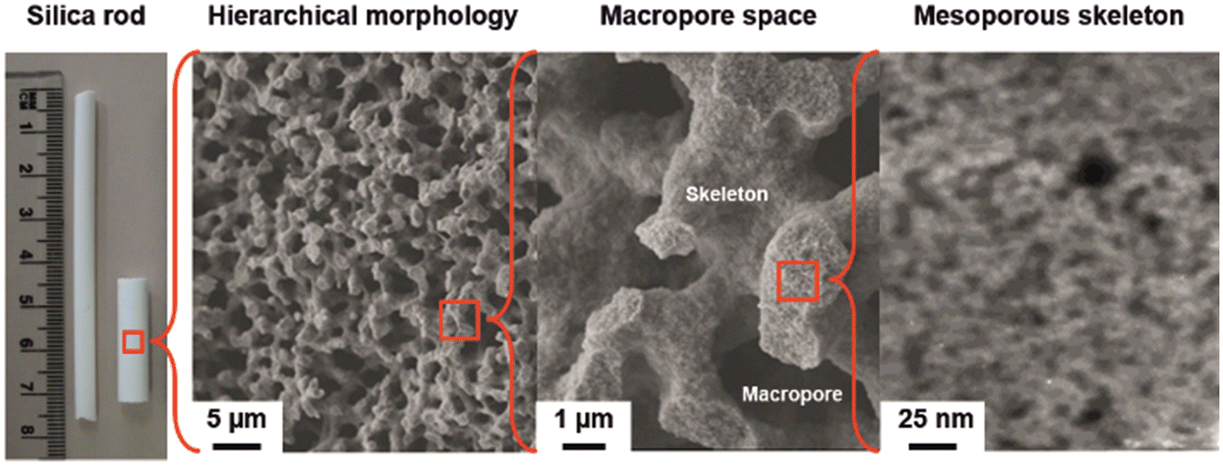 | ||
| Fig. 2 Hierarchically structured silica monolith. The macropores form an interskeleton network of flow-through channels dedicated to advection-dominated transport, while transport in the intraskeleton mesopores remains diffusion-limited. Adapted with permission from Stoeckel et al.52 | ||
Four SILP thicknesses were realized in this work (dSILP = 1, 3, 5, and 15 nm), ranging from the thin-SILP-limit (dSILP = 1 nm), below which a uniform monolayer of [BMIM][BF4] is difficult to establish on the silica surface considering the molecular structure of the supported IL, to the thick-SILP-limit (dSILP = 15 nm), where the ∼30 nm wide mesopores are completely filled with [BMIM][BF4]. SILP thicknesses with applied IL volumes and amounts of Rh-1 catalyst in the SILPs are summarized in Table S2 (ESI†). The hydrosilylation of PA with DMPS in the presence of Rh-1 under continuous flow was accomplished by adapting the two-dimensional microreaction-separation setup shown in Fig. 3.55 While the first dimension serves for the management of the reaction, the second one involves the chromatographic separation of the isomers as well as their subsequent quantification. In the first dimension, a binary pump (4, Fig. 3) was employed to deliver the substrate solution in MTBE to the microreactor fixed in a temperature-controlled oven compartment (8, Fig. 3) at a precisely adjustable and constant volumetric flow rate Q. The residence time of the substrate solution on the microreactor (and thus the reaction time) was therefore controlled by the pump flow rate and reflects the volume in the monolith available to the pumped solution.
 | ||
| Fig. 3 Photograph of the two-dimensional continuous-flow platform used to study the hydrosilylation reaction between PA and DMPS with Rh-1 in the SILP formed by [BMIM][BF4] on a macro–mesoporous silica monolith (cf.Fig. 2). An injection valve (5) behind the microreactor compartment (8) connects the first (reaction) dimension with the second (analytical) dimension, which enables chromatographic separation of the injected reaction solution on a phenyl-hexyl-modified UHPLC column (7) and online analysis of the separated compounds with a diode-array detector (9). | ||
To arrive at quantitative information about the reaction solution, the second dimension was coupled online to the first one to allow for the separation of the targeted isomers by ultrahigh-performance liquid chromatography (UHPLC)56 as well as their detection with a diode-array detector. Both dimensions were connected by a 2-position/6-port valve (5, Fig. 3). Continuous-flow conditions were imposed by flushing the microreactor with the substrate solution at Q = 0.066 mL min−1, which translates into a reaction time of trct = 20 min. This time was adjusted to enable a meaningful comparison between the different reactor loadings with SILP and catalyst (cf. Table S2†) rather than to maximize conversion. As a consequence, unreacted starting materials were generally present in these runs (as can be recognized in Fig. 4). Complementary to the reaction time trct, the total experiment time (ttotal) is the overall time for which the microreactor was monitored under a given set of reaction (continuous-flow) conditions. For example, as both yield and selectivity (eqn (1) and (2) below) were repeatedly determined over a total period of 600 minutes, then ttotal = 600 min for this experiment with the selected SILP thickness, catalyst and substrate concentrations, reaction time, and reaction temperature.
 | ||
| Fig. 4 Chromatogram of the reaction solution, recorded by UV/vis diode-array detection at 260 nm, highlighting the baseline separation of compounds 1–5. Column: 3.0 mm inner diameter × 100 mm length packed with phenyl-hexyl-modified, fully porous silica particles (1.8 μm particle size, 9.5 nm mesopore size), mobile phase: 75/25 (v/v) methanol/water, flow rate: 0.6 mL min−1, column backpressure: 800 bar. | ||
The peak areas of the baseline-separated compounds of interest, i.e., β(Z)- and β(E)-isomers, were converted into masses using calibration curves. Relative chromatographic yields of the individual isomers and Z/E-selectivities were quantified with these data according to
 | (1) |
 | (2) |
One prerequisite for these continuous-flow studies is a fast baseline separation of the compounds of interest, because a short separation cycle allows to monitor yield and selectivity at high temporal resolution over an experiment (ttotal) and address, for example, the influence of dSILP in a series of experiments. For apolar molecules like compounds 1–5 (Scheme 2), a phenyl-hexyl silica column was found appropriate, as that surface chemistry reflects the presence of the aromatic phenyl groups in all these hydrosilylation compounds, offering selective interactions.57Fig. 4 highlights their baseline separation in less than 20 minutes using 75/25 (v/v) methanol/water as UHPLC eluent at a flow rate of 0.6 mL min−1. This in turn enabled the quantitative analysis of all compounds via total numerical integration of their chromatographic peaks together with the acquired calibration curves. As can be seen in Fig. 4, the bottleneck in this analysis was particularly the baseline separation of the α-isomer from the β(Z)-isomer to allow for an unbiased analysis of the latter.
Accordingly, this optimized UHPLC method was implemented as default protocol in the second (separation) dimension of the setup shown in Fig. 3. With this implementation, we were prepared for a deeper investigation of mechanistic aspects of the hydrosilylation reaction occurring in the SILP, with the main focus on the determination of the yields of the β(Z)- and β(E)-isomers and, thus, of Z/E-selectivity for each SILP thickness over extended experiment times (ttotal = 600 min). Both reaction time (trct = 20 min) and reaction temperature (T = 50 °C) were constant during all experiments in which the four SILP thicknesses (Table S2†) were analysed.
The basic data sets recorded with the four experiments are summarized in Fig. 5 as relative yield for each isomer and in Fig. 6 in the form of Z/E-selectivity (see Tables S3 and S4† for associated weights and moles of the two isomers). Three important observations can be made from the yields of the β(Z)- and β(E)-isomers in combination with the four different SILP thicknesses (dSILP = 15, 5, 3, and 1 nm). First, compared to dSILP = 15 nm, none of the yields for dSILP < 15 nm reaches a steady-state even during the extended monitoring periods of 10 hours. While the yields mostly show only small changes and overall reveal a smooth progression, a true steady-state with constant yield is never attained. For dSILP = 15 nm, however, a steady-state in the yields is recognizable after ∼2 hours, characterized by a relatively low mβ(Z)/mβ(E)-ratio of ∼0.041. That is, with a thick SILP layer (mesopores completely filled with IL), the reactor constantly produces almost exclusively the β(E)-isomer. Second, for dSILP < 15 nm the relative β(E)-isomer content decreases over time (and with decreasing SILP thickness) while at the same time, the β(Z)-isomer content rises gently with dSILP = 5 and 3 nm. The strongest increase in the β(Z)-isomer content was observed for the 1 nm-thick SILP after texp ≈ 130 min and continued until the end of the experiment (ttotal = 600 min). In fact, the β(Z)-isomer content even exceeded the one of the β(E)-isomer (for texp > 400 min), which remained unseen with the other SILP thicknesses. Summarizing, Fig. 5 shows that there is a systematic development in the relative yields of the two isomers with decreasing SILP thickness, which starts at the high and constant β(E)-isomer level for dSILP = 15 nm and climaxes in the boost of the β(Z)-isomer yield with the thinnest SILP (dSILP = 1 nm).
 | ||
| Fig. 5 Comparison of relative yields of the produced β(Z)- and β(E)-isomers viaeqn (1) over the course of the four continuous-flow experiments (ttotal = 600 min) with varied SILP thickness. The SILP thickness dSILP was adjusted between (A) 15 nm (thick-SILP-limit), (B) 5 nm, (C) 3 nm, and (D) 1 nm (thin-SILP-limit). Reaction time, trct = 20 min; reaction temperature, T = 50 °C. Weights and moles of β(Z)- and β(E)-isomers underlying the reported yields can be found in Tables S3 and S4 (ESI†). | ||
 | ||
| Fig. 6 Comparison of Z/E-selectivities viaeqn (2) over the course of the four continuous-flow experiments with varied SILP thickness (cf.Fig. 5). Reaction time, trct = 20 min; reaction temperature, T = 50 °C. | ||
The peculiar rise in yield seen for the β(Z)-isomer with the 1 nm-thick SILP manifests itself also in the Z/E-selectivities, which are shown in Fig. 6 for all four experiments from Fig. 5. Clearly mβ(Z)/mβ(E) increases with decreasing SILP thickness. After 600 min, mβ(Z)/mβ(E) = 0.041 for dSILP = 15 nm, 0.43 for dSILP = 5 nm, 0.64 for dSILP = 3 nm, and 1.35 for dSILP = 1 nm. Overall, the transition from a thick to a thin SILP layer under continuous-flow conditions is accompanied by a remarkable increase in Z/E-selectivity, that is, by a factor of ∼33. This is in line with earlier findings using surface-functionalized, polymeric, monolithic supports and clearly shows that this effect is independent of the support used.32
Our findings are a result of different catalytic pathways that occur in a thin (1 nm wide) and in thicker SILPs, which explain the different Z/E-selectivities we observed. With increasing SILP layer thickness, the catalytic pathway responsible for the thin-SILP behaviour, i.e., the formation of β(Z)-isomer, becomes increasingly superimposed by those dominating in thicker SILPs, favouring the formation of the β(E)-isomer. It is well known that the structural and dynamic properties of ILs can change dramatically at solid surfaces and under spatial confinement, in particular.58 Indeed, their structure–transport relationships are modulated by interactions of the cations and anions with the support surface, e.g., with silanol groups of the amorphous silica in the monolithic microreactor employed in the present work. As a consequence, structural ordering phenomena and a slow-down of the translational and rotational ion dynamics are often observed in ILs near solid surfaces.59–62
For [BMIM][BF4] used in this work, insightful results have been derived with molecular dynamics simulations conducted in a slit-pore confined by amorphous silica walls.62,63 Density oscillations were observed near the walls for both cations and anions indicating a layering effect, which is stronger for the [BF4] anions than for the [BMIM] cations, as the former are more symmetric and smaller than the latter. In addition, the [BMIM] cations exhibit a preferred orientation in their first layer, where the methyl group and butyl tail point towards the silica wall and pore centre, respectively, and the imidazolium ring aligns with the surface. Furthermore, regarding the ion dynamics at a temperature of 300 K, the cation and anion motions are slowed down by roughly two orders of magnitude at the surface with respect to the centre of the pore. Here, the retardation of the ion dynamics rapidly declines with increasing distance from the surface and mainly affects the first two [BMIM][BF4] layers.
These findings are highly relevant to our work, as distinctive density layers and strong mobility gradients exist near the surface. As a consequence, self-diffusion and structural relaxation are much slower there than in the bulk IL. The effects culminate in a highly dense and ordered (quasi-solid) first [BMIM][BF4] layer at the silica surface, which is about 1 nm wide and characterized by a very low (quasi-frozen) mobility of the ionic species. It is reasonable to assume that in this quasi-frozen state the catalyst also experiences a slowdown of its translational and rotational dynamics and will most likely prefer the conformation that is found in the solid state, which we successfully determined by single-crystal X-ray analysis. Rh-1 crystallizes in the triclinic space group P![[1 with combining macron]](https://www.rsc.org/images/entities/char_0031_0304.gif) with a = 975.6(5) pm, b = 1114.7(5) pm, c = 1352.7(7) pm, α = 75.446(16)°, β = 83.737(16)°, γ = 73.626(17)°, Z = 2. Relevant bond lengths and angles are summarized in Fig. 7. The most striking feature is that in the solid state, the pyridine group coordinates to the Rh-centre, thereby preventing any rotation of the NHC, which is of utmost relevance for explaining our experimental findings (vide infra).
with a = 975.6(5) pm, b = 1114.7(5) pm, c = 1352.7(7) pm, α = 75.446(16)°, β = 83.737(16)°, γ = 73.626(17)°, Z = 2. Relevant bond lengths and angles are summarized in Fig. 7. The most striking feature is that in the solid state, the pyridine group coordinates to the Rh-centre, thereby preventing any rotation of the NHC, which is of utmost relevance for explaining our experimental findings (vide infra).
 | ||
| Fig. 7 Single-crystal X-ray structure of Rh-1 (cf.Fig. 1). Relevant bond lengths (pm) and angles (°): Rh(1)–C(1) 197.4(10), Rh(1)–N(3) 213.4(8), Rh(1)–C(18) 213.7(9), Rh(1)–C(19) 214.4(10), Rh(1)–C(22) 220.6(9), Rh(1)–C(23) 222.3(10); C(1)–Rh(1)–N(3) 78.8(4), C(1)–Rh(1)–C(18) 96.1(4), N(3)–Rh(1)–C(18) 160.3(3), C(1)–Rh(1)–C(19) 100.0(4), N(3)–Rh(1)–C(19) 162.8(3), C(18)–Rh(1)–C(19) 36.6(3), C(1)–Rh(1)–C(22) 161.6(4), N(3)–Rh(1)–C(22) 94.6(3), C(18)–Rh(1)–C(22) 95.5(4), C(19)–Rh(1)–C(22) 81.1(4), C(1)–Rh(1)–C(23) 161.8(4), N(3)–Rh(1)–C(23) 98.0(3), C(18)–Rh(1)–C(23) 80.9(4), C(19)–Rh(1)–C(23) 88.3(4), C(22)–Rh(1)–C(23) 35.5(3). | ||
For comparison, the single-crystal X-ray structure of Rh-2 together with relevant bond lengths and angles is shown in Fig. 8. Rh-2 crystallises in the monoclinic space group C2 with a = 2068.43(17) pm, b = 826.12(6) pm, c = 1516.11(13) pm, α = γ = 90°, β = 117.168(7)°, Z = 4.
 | ||
| Fig. 8 Single-crystal X-ray structure of Rh-2 (cf.Fig. 1). Relevant bond lengths (pm) and angles (°): Rh(1)–C(1) 202.4(3), Rh(1)–N(3) 205.5(3), Rh(1)–C(11) 207.7(10), Rh(1)–C(12) 217.0(11), Rh(1)–C(16) 217.8(8), Rh(1)–C(15) 225.7(7); C(1)–Rh(1)–N(3) 92.26(11), C(1)–Rh(1)–C(11) 89.8(3), N(3)–Rh(1)–C(11) 161.1(4), C(1)–Rh(1)–C(12) 90.9(3), N(3)–Rh(1)–C(12) 160.9(4), C(11)–Rh(1)–C(12) 37.73(15), C(1)–Rh(1)–C(16) 168.0(4), N(3)–Rh(1)–C(16) 92.0(2), C(11)–Rh(1)–C(16) 82.7(3), C(12)–Rh(1)–C(16) 88.8(3), C(1)–Rh(1)–C(15) 157.1(4), N(3)–Rh(1)–C(15) 88.6(2), C(11)–Rh(1)–C(15) 96.8(3), C(12)–Rh(1)–C(15) 81.3(3), C(16)–Rh(1)–C(15) 34.3(2). | ||
Notably, the very low mobility will also affect the diffusion of solute molecules (that interact with the IL) in and through the density and mobility gradients of a SILP. For example, using fluorescence recovery after photobleaching (FRAP) in confocal microscopy,64 it has been demonstrated that the diffusivity of a neutral dye in [BMIM][PF6] confined in mesoporous silica is about two orders of magnitude lower than in the bulk IL. Similarly, the densified structure and slow dynamics of the SILP over a distance of 1–2 nm from the surface is expected to have an impact on the reactant molecules entering and moving within this region (in order to get in contact and arranged with the catalyst molecules residing there) and on the product molecules as they leave the local catalytic environment and the SILP after the reaction.
Compounds 1–5 dissolve well in the bulk IL. In the rigid, 1 nm-thick part of the SILP the reaction proceeds slower and diffusion of the larger products is delayed, which must result in an enrichment of the produced isomers in a thin SILP. To get evidence for a slower reaction and especially a slow release of the hydrosilylation products from the quasi-frozen part of the SILP, we performed continuous-flow experiments for two SILP thicknesses, i.e., for dSILP = 1 nm and dSILP = 15 nm, with a subsequent rest period of the microreactor in pure MTBE of 18 hours, followed by workup of the MTBE phase. The results are compared in Fig. 9 with respect to Z/E-selectivity.
 | ||
| Fig. 9 Continuous-flow experiments with thin SILP (dSILP = 1 nm) and thick SILP (dSILP = 15 nm), followed by a flushing step of the microreactor with pure MTBE and a rest period (stopped flow) of 18 hours. Afterwards, the MTBE solution was flushed out and the effluent analysed for Z/E-selectivity using the second dimension of the setup depicted in Fig. 3. | ||
The first data point recorded ∼20 min after the rest period of 18 hours corresponds to an elution volume (0.066 mL min−1 × 20 min = 1.32 mL) of roughly one reactor void volume (Vvoid ≈ 1.46 mL, ESI†). This point therefore represents the (almost entire) MTBE solution that had contact with the SILP throughout the 18 hours. Remarkably, a Z/E-ratio of 4.72 was received for the thin SILP. Such a high value has never been indicated or even measured in our continuous-flow experiments. It demonstrates that predominantly the β(Z)-isomer was produced and then trapped in the thin (rigid) SILP. In contrast, a Z/E-ratio of only 0.15 was observed for the thick SILP after this long extraction period, which confirms our conjecture that mostly β(E)-isomer was produced and retained in the bulk SILP saturating the mesopores of the monolith. Control experiments were performed to ensure that Rh-1 does not catalyse the isomerization of the less stable β(Z)-isomer into the thermodynamically favoured β(E)-isomer during the rest period21 and thereby cause a bias in the subsequently analysed isomer pattern. For this purpose, microreactors with freshly prepared thin or thick SILP (containing Rh-1) were flushed with MTBE containing only a mixture of β(E)- and β(Z)-isomers that were beforehand synthesized and isolated. This isomer solution was then also allowed to rest in the microreactor for 18 hours, as in the extraction experiment, and then analysed. In fact, no changes in the original isomer composition could be detected after this period, implying that Rh-1 does not catalyse Z/E-isomerization. The strong dependence of the β(Z)/β(E)-ratio from the thickness of the SILP layer can thus be fully explained considering both, the structure of the catalyst (and of the resulting transition states during hydrosilylation) and the different morphologies of the SILP layers with different thickness.
Clearly, the SILP possesses a substantial gradient in terms of morphology and rigidity as we move from the pore walls to the centre of the pores. In the thin-SILP-limit (dSILP ≈ d1, Fig. 10), the SILP predominantly consists of a quasi-frozen monolayer with a much lower diffusive mobility of the substrates and products than in the bulk IL. The cationic catalyst will also be firmly held in the rigid SILP, most likely supported by silanophilic interactions with the surface (as implied by its positioning in Fig. 10). As a consequence, the integration of the reactants into (as well as the release of the even larger products from) the rigid SILP, indicated by the phase transfer in Fig. 10, is slow, as confirmed by the extraction experiment (Fig. 9). On the other hand, in the thick-SILP-limit (dSILP ≈ d2, Fig. 10), the SILP mostly consists of bulk SILP, which exhibits the properties (local density and diffusive mobility) of the bulk IL. There, the catalyst can move more freely as compared to the rigid SILP and also phase transfer of reactants and products between the mobile MTBE phase and the bulk region of the SILP is faster than between MTBE and rigid SILP.
 | ||
| Fig. 10 Schematic representation of relevant structural and dynamic aspects in the continuous-flow hydrosilylation reaction between PA and DMPS with Rh-1 in the SILP formed by [BMIM][BF4] in the ∼30 nm wide mesopores of a (macro–mesoporous) silica monolith. | ||
The observed preferential formation of the β(Z)-isomer by Rh-1 in the thin SILP can be accounted for by the quasi-frozen IL resulting in a preferred transition state with the pyridine group coordinating to the Rh-centre, as found in the solid-state structure of Rh-1 (Scheme 3). The resulting β(Z)-selectivity can be explained by the modified Chalk–Harrod mechanism:9,65,66 Formation of a Rh-hydride is followed by the coordination of the alkyne. Alkyne insertion into the Rh–Si bond leads to the β(Z)-silylvinylidene intermediate. Subsequently, two reaction pathways can emerge, depending on whether the reaction proceeds in the bulk or in the quasi-frozen SILP. Thus, the formed β(Z)-silylvinylidene may lead to the β(E)-silylvinylidene and, consequently, to the β(Z)-vinylsilane (red pathway). The quasi-frozen SILP restricts the rotation of the NHC of the confined catalyst, which results in a strong steric interaction between the pyridine or mesityl moiety and the SiMe2Ph group. Rotation of the HC–CPh bond eliminates this steric interaction making the β(E)-silylvinylidene the preferred configuration, which finally results in the formation of the β(Z)-vinylsilane. Vice versa, the bulk SILP allows for a decoordination of the pyridine group and rotation of the NHC, which places less steric constraints on the initial β(Z)-silylvinylidene, resulting in predominant formation of the β(E)-vinylsilane. The joint role of a coordinating pyridine group and the restricted mobility within a thin SILP was confirmed by running the same hydrosilylation reaction in a thin SILP (dSILP = 1 nm) at 50 °C by the action of Rh(I) NHC catalysts that did not possess any chelating groups, i.e., Rh-2 and Rh-3 (Fig. 1). With these Rh-catalysts, mβ(Z)/mβ(E) did not exceed 0.65 (Rh-2) and 0.12 (Rh-3) over a reaction time of 140 min and 540 min, respectively (cf. Fig. S7 and Table S5 in the ESI†).
 | ||
| Scheme 3 Modified Chalk–Harrod mechanism for the preferential formation of β(Z)- or β(E)-vinylsilane isomer in the continuous-flow hydrosilylation reaction between PA and DMPS with Rh-1 in the SILP formed by [BMIM][BF4] on a macro–mesoporous silica monolith. | ||
All this fits to our experimental data, where starting in the thin-SILP-limit (dSILP = 1 nm), the dominating Z-selectivity in the rigid SILP becomes increasingly superimposed by E-selectivity for larger SILP thickness (dSILP = 3 and 5 nm) in the bulk SILP, until the β(E)-isomer dominates and is correspondingly produced at a constantly high level, without sign of increasing Z/E-selectivity over time, in the thick-SILP-limit (dSILP = 15 nm, cf.Fig. 5).
Conclusions
Continuous-flow studies of the hydrosilylation reaction between PA (1) and DMPS (2) in the presence of the cationic Rh-NHC complex Rh-1, taking place within the SILP formed by [BMIM][BF4] on the mesopore surface of a macro-mesoporous silica monolith, have revealed a clear dependence of Z/E-selectivity on the SILP thickness varied from dSILP = 1 nm to 15 nm. In the thick-SILP-limit (d2 ≫ d1 and dSILP ≈ d2, Fig. 10), the SILP mostly consists of bulk IL, in which hydrosilylation leads to the predominant formation of the thermodynamically more stable β(E)-vinylsilane isomer (5). The thick-SILP-limit is approached in our experiments as the mesopores are completely filled with IL (dSILP = 15 nm), while the thin-SILP-limit is reached for dSILP = 1 nm (d2 → 0 and dSILP ≈ d1, Fig. 10). In the latter situation, the SILP mostly consists of a quasi-frozen monolayer of IL cations and anions, in which the catalyst is firmly embedded experiencing restricted mobility. In this thin-SILP-limit, hydrosilylation results in the predominant formation of the kinetically favoured β(Z)-vinylsilane isomer (4) via generation of the β(E)-silylvinylidene intermediate through isomerization of the β(Z)-silylvinylidene (Scheme 3).From a more general point of view, our work highlights the importance of SILP morphology and, in particular, of the adjusted SILP thickness, on the structural and transport dynamics as well as the selectivity of reactions occurring inside a SILP. Implementation as continuous-flow experiment with UHPLC-separation based online analytics has been essential in recognizing the evolution of Z/E-selectivity over hours and thereby tracing the slow release of the Z-isomer from the rigid part of the SILP as a function of dSILP. To the best of our knowledge, this is the first example for a confinement jointly generated by a tailored structural motif in a catalyst (chelating ligand) and the morphology of a very thin IL layer. We therefore anticipate similar effects of rigid vs. bulk SILP microstructure, which become convoluted as the SILP thickness increases from thin to thick, to be manifested also in other reactions, e.g., in the closely related hydroboration and hydroamination reactions.
Experimental
Chemicals and columns
Methanol (HPLC grade) came from VWR Chemicals (Darmstadt, Germany) and water was used as received from a Milli-Q gradient purification system (Millipore, Bedford, MA). HPLC grade MTBE and CH2Cl2 as well as PA (98%), DMPS (≥98%), and [BMIM][BF4] (≥97%) were obtained from Sigma Aldrich (St. Louis, MO). DMPS was stored at 4 °C, while MTBE was dried over sodium to remove residual water and stored under inert gas with a molecular sieve (3 Å) until use. Catalysts Rh-1,24Rh-2,67 and Rh-3 (ref. 68) were prepared according to established protocols. For hydrosilylation, we used a macro–mesoporous silica monolith received from Merck KGaA (Darmstadt, Germany) as 4.6 mm inner diameter × 100 mm length column clad in polyether ether ketone. The silica monolith had mean macropore and mesopore sizes of 1.84 μm and 32.9 nm, respectively. The reaction mixture (compounds 1–5, Scheme 2) was separated on a 3.0 mm inner diameter × 100 mm length UHPLC column packed with phenyl-hexyl-modified, fully porous silica particles with nominal mean particle and mesopore sizes of 1.8 μm and 9.5 nm, respectively (Agilent Technologies, Santa Clara, CA).Microreactor operation
Continuous-flow hydrosilylation was realized by implementation of commercially available HPLC instrumentation, as depicted in Fig. 3. Substrate solution (25 mM PA and 32.5 mM DMPS in dry, absolute MTBE) was connected to a binary pump with a septum and metal capillary. This solution was pumped at a flow rate of Q = 0.066 mL min−1 through the reactor placed in a thermostatted compartment (50![[thin space (1/6-em)]](https://www.rsc.org/images/entities/char_2009.gif) °C). The reaction solution from the microreactor was transferred by a valve to the second (analytical) dimension, where the reaction mixture was separated using UHPLC (cf.Fig. 4) and analyzed with a diode-array detector (260 nm).
°C). The reaction solution from the microreactor was transferred by a valve to the second (analytical) dimension, where the reaction mixture was separated using UHPLC (cf.Fig. 4) and analyzed with a diode-array detector (260 nm).
Hardware components (as shown in Fig. 3)
1, substrate solution; 2, autosampler (Agilent 1290 Infinity II Series, G7129B); 3, quaternary pump for second-dimension online analytics (Agilent 1290 Infinity II Series, G7104A); 4, binary pump for first-dimension reaction control (Agilent 1290 Infinity II Series, G7120A); 5, 2-position/6-port valve for connecting first and second dimensions (Agilent 1290 Infinity Series, G1170A); 6, online diode-array detector (Agilent 1260 Infinity II Series, G7115A); 7, thermostatted compartment with UHPLC column (Agilent 1290 Infinity II Series, G7116B); 8, thermostatted compartment with monolithic microreactor (Agilent 1290 Infinity II Series, G7116B); 9, online diode-array detector (Agilent 1290 Series, G4212A).SILP preparation
For impregnation, the monolith was flushed with a solution of [BMIM][BF4] in CH2Cl2 (also containing Rh-1). After removal of CH2Cl2 by overnight vacuum-drying, a layer of the catalyst-containing IL remained on the monolith surface, almost exclusively (>99%) intraskeleton mesopore surface. Variation of the SILP thickness was achieved by adjusting the IL volume deposited inside the mesopores (VIL) | (3) |
| msilica = (Vcolumn − Vvoid)ρsilica | (4) |
With Vvoid determined as the elution volume of a small, non-adsorbing tracer on the monolithic column, verified by the elution of PA in pure acetonitrile, we found msilica = 0.447 g (additional details behind the determination of msilica can be found in the ESI†). For a targeted SILP thickness of 1 nm, for example, VIL is then given by
| VIL = 1 × 10−7 cm × 0.447 g × 110 × 104 cm2 g−1 = 0.05 mL |
Stopped-flow experiments
Experiments were run for dSILP = 1 nm and 15 nm. After the (standard) continuous-flow experiment, in which the reactor was fed with reaction solution (25 mM PA and 32.5 mM DMPS in MTBE) for 600 min, the pumping system was switched to pure MTBE and the reactor flushed until no substrate and product molecules could be detected any longer in the effluent. Then, the flow was stopped and the reactor left at rest in pure MTBE for 18 hours. This long extraction period guaranteed a sufficient diffusive release of the trapped β(Z)- and β(E)-isomers from the SILP into the MTBE phase. After this period the flow was restarted (pure MTBE, Q = 0.066 mL min−1) and the reactor effluent analysed for the amount of the two isomers released from the corresponding SILP phase.Data availability
• Data for this article, including primary data for the NMR spectra, kinetic measurements, and chromatograms are available at the Data Repository of the University of Stuttgart (DARUS) [https://darus.uni-stuttgart.de] in connection with the DOI of the published paper.• Further data (experimental details, chromatograms, NMR spectra, crystallographic details for Rh-1 and Rh-2) supporting this article have been included as part of the ESI.†
• Deposition numbers CCDC 2430795 (Rh-1) and 2441044 (Rh-2) contain the supplementary crystallographic data for this paper. These data are provided free of charge by the joint Cambridge Crystallographic Data Centre and Fachinformationszentrum Karlsruhe Access Structures Service.
Author contributions
André Böth: formal analysis, investigation, validation, visualization, writing – original draft. Florian Kaltwasser: formal analysis, investigation, validation, visualization, writing – review & editing. Christian Priedigkeit: formal analysis, investigation. Boshra Atwi: investigation: resources. Wolfgang Frey: formal analysis. Michael R. Buchmeiser: conceptualization, funding acquisition, resources, supervision, writing – original draft. Ulrich Tallarek: conceptualization, funding acquisition, methodology, resources, supervision, writing – original draft. All authors have approved the final version of the manuscript.Conflicts of interest
The authors declare no competing financial interests.Acknowledgements
Financial support by the Deutsche Forschungsgemeinschaft DFG (German Research Foundation, project ID 358283783 – SFB 1333/2 2022) is gratefully acknowledged. We further thank Agilent Technologies (Waldbronn, Germany) for support with analytical equipment and Benjamin Peters (Instrumental Analytics R&D, Merck KGaA, Darmstadt, Germany) for the gift of monolithic silica columns.Notes and references
- L. N. Lewis, J. Stein, Y. Gao, R. E. Colborn and G. Hutchins, Platinum Met. Rev., 1997, 41, 66–75 CrossRef.
- L. Cornelissen, V. Cirriez, S. Vercruysse and O. Riant, Chem. Commun., 2014, 50, 8018–8020 RSC.
- J. Szudkowska-Frątczak, G. Hreczycho and P. Pawluć, Org. Chem. Front., 2015, 2, 730–738 RSC.
- T. Komiyama, Y. Minami and T. Hiyama, ACS Catal., 2017, 7, 631–651 CrossRef.
- A. Vignesh, J. Liu, Z. Wang, Y. Liu and Z. Ke, Org. Chem. Front., 2024, 11, 576–596 RSC.
- B. Marciniec, H. Maciejewski and P. Pawluć, Hydrosilylation of Carbon–Carbon Multiple Bonds—Application in Synthesis and Materials Science, in: Organosilicon Compounds, ed. V. Y. Lee, Academic Press, New York, 2017, vol. 2, pp. 169–217 Search PubMed.
- M. A. Brook, Silicon in Organic, Organometallic and Polymer Chemistry, John Wiley & Sons, New York, 2000 Search PubMed.
- A. K. Franz and S. O. Wilson, J. Med. Chem., 2013, 56, 388–405 CrossRef PubMed.
- B. Marciniec, Hydrosilylation of Alkynes and Their Derivatives, in: Hydrosilylation. Advances in Silicon Science, ed. B. Marciniec, Springer, Dordrecht, 2009, vol. 1, pp. 53–86 Search PubMed.
- A. Zanardi, E. Peris and J. A. Mata, New J. Chem., 2008, 32, 120–126 RSC.
- S. Demir, Y. Gökçe, N. Kaloğlu, J. B. Sortais, C. Darcel and I. Özdemir, Appl. Organomet. Chem., 2013, 27, 459–464 CrossRef.
- J. Sun and L. Deng, ACS Catal., 2016, 6, 290–300 CrossRef.
- Y. Mutoh, Y. Mohara and S. Saito, Org. Lett., 2017, 19, 5204–5207 CrossRef PubMed.
- P. Wang, Y. Lai, P. Wang, X. Leng, J. Xiao and L. Deng, J. Am. Chem. Soc., 2021, 143, 12847–12856 CrossRef PubMed.
- R. R. Behera, R. Saha, A. A. Kumar, S. Sethi, N. C. Jana and B. Bagh, J. Org. Chem., 2023, 88, 8133–8149 CrossRef.
- M. González-Lainez, M. V. Jiménez, V. Passarelli and J. J. Pérez-Torrente, Dalton Trans., 2023, 52, 11503–11517 RSC.
- A. Tyagi, S. Yadav, P. Daw, C. Ravi and J. K. Bera, Polyhedron, 2019, 172, 167–174 CrossRef.
- A. Mumcu, M. O. Karataş, N. Özedmir, A. Erdoğan and H. Küçükbay, J. Organomet. Chem., 2023, 997, 122791 CrossRef.
- J. J. Pérez-Torrente, D. H. Nguyen, M. V. Jiménez, F. J. Modrego, R. Puerta-Oteo, D. Gómez-Bautista, M. Iglesias and L. A. Oro, Organometallics, 2016, 35, 2410–2422 CrossRef.
- R. Takeuchi and I. Ebata, Organometallics, 1997, 16, 3707–3710 CrossRef.
- L. P. Morales-Cerón, P. Lara, J. López-Serrano, L. L. Santos, V. Salazar, E. Álvarez and A. Suárez, Organometallics, 2017, 36, 2460–2469 CrossRef.
- R. Puerta-Oteo, J. Munárriz, V. Polo, M. V. Jiménez and J. J. Pérez-Torrente, ACS Catal., 2020, 10, 7367–7380 Search PubMed.
- W. A. Solomonsz, G. A. Rance, M. Suyetin, A. La Torre, E. Bichoutskaia and A. N. Khlobystov, Chem. – Eur. J., 2012, 18, 13180–13187 Search PubMed.
- P. K. R. Panyam, B. Atwi, F. Ziegler, W. Frey, M. Nowakowski, M. Bauer and M. R. Buchmeiser, Chem. – Eur. J., 2021, 27, 17220–17229 CrossRef PubMed.
- M. Roemer, V. R. Gonçales, S. T. Keaveney, I. Pernik, J. Lian, J. Downes, J. J. Gooding and B. A. Messerle, Catal. Sci. Technol., 2021, 11, 1888–1898 RSC.
- M. Roemer, S. T. Keaveney, J. E. Downes, S. Gautam, J. J. Gooding and B. A. Messerle, Catal. Sci. Technol., 2022, 12, 226–236 RSC.
- B. Sánchez-Page, J. Munarriz, M. V. Jiménez, J. J. Pérez-Torrente, J. Blasco, G. Subias, V. Passarelli and P. Patricia Álvarez, ACS Catal., 2020, 10, 13334–13351 CrossRef.
- A. Riisager and R. Fehrmann, Supported Ionic Liquid Phase Catalysts, in: Ionic Liquids in Synthesis, ed. P. Wasserscheid and T. Welton, Wiley-VCH, Weinheim, 2008, vol. 2, pp. 527–558 Search PubMed.
- C. van Doorslaer, J. Wahlen, P. Mertens, K. Binnemans and D. de Vos, Dalton Trans., 2010, 39, 8377–8390 RSC.
- R. Kukawka, A. Pawlowska-Zygarowicz, J. Dzialkowska, M. Pietrowski, H. Maciejewski, K. Bica and M. Smiglak, ACS Sustainable Chem. Eng., 2019, 7, 4699–4706 CrossRef.
- J. Dupont, B. C. Leal, P. Lozano, A. L. Monteiro, P. Migowski and J. D. Scholten, Chem. Rev., 2024, 124, 5227–5420 CrossRef PubMed.
- P. K. R. Panyam and M. R. Buchmeiser, Faraday Discuss., 2023, 244, 39–50 RSC.
- G. Franciò, U. Hintermair and W. Leitner, Philos. Trans. R. Soc., A, 2015, 373, 20150005 CrossRef PubMed.
- E. García-Verdugo, B. Altava, M. I. Burguete, P. Lozano and S. V. Luis, Green Chem., 2015, 17, 2693–2713 RSC.
- J. M. Marinkovic, A. Riisager, R. Franke, P. Wasserscheid and M. Haumann, Ind. Eng. Chem. Res., 2019, 58, 2409–2420 CrossRef CAS.
- M. Aubermann, M. Haumann, D. Wisser and P. Wasserscheid, ACS Sustainable Chem. Eng., 2022, 10, 6973–6980 CrossRef CAS.
- A. Billion, A. Vogel, J. Schulte, H. Scherer and I. Krossing, ChemCatChem, 2023, 15, e202300844 CrossRef CAS.
- P. Latos, A. Wolny and A. Chrobok, Materials, 2023, 16, 2106 CrossRef CAS PubMed.
- B. Autenrieth, W. Frey and M. R. Buchmeiser, Chem. – Eur. J., 2012, 18, 14069–14078 CrossRef CAS.
- B. Sandig and M. R. Buchmeiser, ChemSusChem, 2016, 9, 2917–2921 CrossRef CAS.
- B. Sandig, L. Michalek, S. Vlahovic, M. Antonovici, B. Hauer and M. R. Buchmeiser, Chem. – Eur. J., 2015, 21, 15835–15842 CrossRef CAS PubMed.
- A. Odedra, K. Geyer, T. Gustafsson, R. Gilmour and P. Seeberger, Chem. Commun., 2008, 3025–3027 RSC.
- M. Jankowska-Wajda, R. Kukawka, M. Smiglak and H. Maciejewski, New J. Chem., 2018, 42, 5229–5236 RSC.
- H. Acikalin, P. K. R. Panyam, A. W. Shaikh, D. Wang, S. R. Kousik, P. Atanasova and M. R. Buchmeiser, Macromol. Chem. Phys., 2023, 224, 2200234 CrossRef CAS.
- C.-L. Tavera-Méndez, A. Bergen, S. Trzeciak, F. W. Heinemann, R. Graf, D. Zahn, K. Meyer, M. Hartmann and D. Wisser, Chem. – Eur. J., 2024, 30, e202303673 CrossRef PubMed.
- G. Guiochon, J. Chromatogr. A, 2007, 1168, 101–168 CrossRef CAS.
- D. Enke, R. Gläser and U. Tallarek, Chem. Ing. Tech., 2016, 88, 1561–1585 CrossRef CAS.
- A. Galarneau, A. Sachse, B. Said, C.-H. Pélisson, P. Boscaro, N. Brun, L. Courtheoux, N. Olivi-Tran, B. Coasne and F. Fajula, C. R. Chim., 2016, 19, 231–247 CrossRef.
- C. P. Haas, T. Müllner, R. Kohns, D. Enke and U. Tallarek, React. Chem. Eng., 2017, 2, 498–511 RSC.
- A. Feinle, M. S. Elsaesser and N. Huesing, Chem. Soc. Rev., 2016, 45, 3377–3399 RSC.
- A. Inayat, B. Reinhardt, J. Herwig, C. Küster, H. Uhlig, S. Krenkel, E. Raedlein and D. Enke, New J. Chem., 2016, 40, 4095–4101 RSC.
- D. Stoeckel, C. Kübel, K. Hormann, A. Höltzel, B. M. Smarsly and U. Tallarek, Langmuir, 2014, 30, 9022–9027 CrossRef PubMed.
- S. Altmaier and K. Cabrera, J. Sep. Sci., 2008, 31, 2551–2559 CrossRef PubMed.
- K. Hormann, T. Müllner, S. Bruns, A. Höltzel and U. Tallarek, J. Chromatogr. A, 2012, 1222, 46–58 CrossRef PubMed.
- A. Böth, T. Roider, F. Ziegler, X. Xie, M. R. Buchmeiser and U. Tallarek, ChemCatChem, 2023, 15, e202201268 CrossRef.
- T. H. Walter and R. W. Andrews, TrAC, Trends Anal. Chem., 2014, 63, 14–20 CrossRef.
- A. Böth, D. Foshag, C. Schulz, B. Atwi, S. E. Maier, D. P. Estes, M. R. Buchmeiser, T. van de Goor and U. Tallarek, J. Chromatogr. A, 2024, 1730, 465165 CrossRef.
- S. Zhang, J. Zhang, Y. Zhang and Y. Deng, Chem. Rev., 2017, 117, 6755–6833 CrossRef PubMed.
- S. Perkin, Phys. Chem. Chem. Phys., 2012, 14, 5052–5062 RSC.
- M. Foroutan, S. M. Fatemi and F. Esmaeilian, Eur. Phys. J. E: Soft Matter Biol. Phys., 2017, 40, 19 CrossRef.
- F. Borghi and A. Podestà, Adv. Phys.: X, 2020, 5, 1736949 Search PubMed.
- R. Köster and M. Vogel, J. Chem. Phys., 2022, 156, 074501 CrossRef.
- T. Pal, C. Beck, D. Lessnich and M. Vogel, J. Phys. Chem. C, 2018, 122, 624–634 CrossRef.
- A. D. Drake, Y. He, F. Ladipo, B. L. Knutson and S. E. Rankin, J. Phys. Chem. B, 2024, 128, 3046–3060 CrossRef.
- A. J. Chalk and J. F. Harrod, J. Am. Chem. Soc., 1965, 87, 16–21 CrossRef.
- L.-W. Chung, Y.-D. Wu, B. M. Trost and Z. T. Ball, J. Am. Chem. Soc., 2003, 125, 11578–11582 CrossRef PubMed.
- I. M. Daubit, M. P. Sullivan, M. John, D. C. Goldstone, C. G. Hartinger and N. Metzler-Nolte, Inorg. Chem., 2020, 59, 17191–17199 CrossRef.
- M. Mayr, K. Wurst, K.-H. Ongania and M. R. Buchmeiser, Chem. – Eur. J., 2004, 10, 1256–1266 CrossRef PubMed.
- H. U. K. Jatoi, M. Goepel, D. Poppitz, R. Kohns, D. Enke, M. Hartmann and R. Gläser, Front. Chem. Eng., 2021, 3, 789416 CrossRef.
- A. Galarneau, Z. Abid, B. Said, Y. Didi, K. Szymanska, A. Jarzębski, F. Tancret, H. Hamaizi, A. Bengueddach, F. Di Renzo and F. Fajula, Inorganics, 2016, 4, 9 CrossRef.
Footnote |
| † Electronic supplementary information (ESI) available: CCDC 2430795 and 2441044. For ESI and crystallographic data in CIF or other electronic format see DOI: https://doi.org/10.1039/d5cy00436e |
| This journal is © The Royal Society of Chemistry 2025 |