 Open Access Article
Creative Commons Attribution 3.0 Unported Licence
Redox-active tin(II) complexes with sterically demanding o-phenylenediamido ligands and their reactivity with organic azides†
Hideki Sugimoto *a,
Akira Yoneda
 a,
Mayuka Yanoa,
Kazunobu Sato
 *b,
Yoshihito Shiota
 c,
Mayuko Miyanishic,
Kazunari Yoshizawa
 *c and
Shinobu Itoh
 *a
*a
aDepartment of Molecular Chemistry, Division of Applied Chemistry, Graduate School of Engineering, Osaka University, Yamadaoka, Suita, Osaka 565-0871, Japan. E-mail: sugimoto@chem.eng.osaka-u.ac.jp; shinobu@chem.eng.osaka-u.ac.jp
bDepartment of Chemistry, Graduate School of Science, Osaka Metropolitan University, 3-3-138, Sugimoto, Sumiyoshi-ku, Osaka 558-8585, Japan. E-mail: sato@omu.ac.jp
cInstitute for Materials Chemistry and Engineering and International Research Center for Molecular System, Kyushu University, Motooka, Nishi-ku, Fukuoka, 819-0395, Japan. E-mail: kazunari@ms.ifoc.kyushu-u.ac.jp
First published on 25th February 2025
Abstract
A series of tin(II) complexes R1 supported by phenylene-1,2-diamido ligands containing a bulky N-substituent TIPT (2,4,2′′,4′′-tetraisopropyl-[1,1′:3′,1′′]terphenyl) and different aromatic substituents R (Cl, H, Me, OMe) at the 4,5-positions and by a naphthalene-2,3-diamido ligand with the TIPT substituent naph1 are synthesised and characterised. Tin(II) complexes SnLMe and SnLPh(tBu)2 supported by phenylene-1,2-diamido ligands with sterically less hindered N-substituents, Ph or 3,5-di-tert-butylphenyl, are also prepared as reference complexes. Crystal structures of R1 and naph1 show that the tin(II) centers are coordinated with the two amido nitrogen atoms of the respective deprotonated chelating ligand and two solvent molecules such as tetrahydrofuran and/or acetonitrile. On the other hand, the tin(II) complex SnLPh(tBu)2 contains only one coordinating solvent molecule, and its tin(II) center exhibits intermolecular interaction with the aromatic ligand moiety of a neighboring tin(II) complex through a 5p–π interaction. The 119Sn NMR signal of R1 in C6D6 shifts from the lower- to higher-magnetic field region as R becomes more electron-withdrawing, which can be explained by assuming that the naked two-coordinate tin(II) complex and solvent-involving three- and/or four-coordinate tin(II) complex exist in equilibrium in solution. The tin(II) complexes with the sterically demanding ligands (R1 and naph1) are more stabilised against hydrolysis when compared with SnLPh and SnLPh(tBu)2. The tin(II) complexes R1 and naph1 undergo one-electron quasi-reversible ligand-based redox oxidation in a range from −0.45 V to +0.13 V vs. Fc/Fc+. The tin(II) complexes having electron-donating groups (R = OMe, Me, H) exhibit intramolecular C–H amination reactivity when treated with trisylazide (2,4,6-triisopropylphenylsulfonyl azide), giving sultam (5,7-diisopropyl-2,3-dihydro-3,3-dimethyl-1,2-benzothiazole-1,1-dioxide) as the product. On the other hand, the tin(II) complexes having electron-withdrawing groups (R = Cl, naph) do not show such reactivity. Such a difference in the reactivity is attributed to availability of a nitrene-radical bound species formed by the reaction. The formation step of the nitrene-radical bound species is analyzed kinetically to reveal that the reaction comprises two steps: binding of the organic azide to the tin(II) centre and successive intramolecular electron transfer from the ligand to the azide moiety to induce dinitrogen (N2) elimination and nitrene-radical formation.
Introduction
Metal complexes with redox-active ligands have attracted much recent attention in current synthetic organic chemistry as well as coordination chemistry, since such ligands can avoid high activation barriers in several types of redox transformation reactions.1–4 Tyrosine in the oxygen-evolving center of photosystem II and galactose oxidase,5,6 porphyrin in cytochrome P450,7 and dithiolene in molybdoenzymes8 are typical examples of such redox-active ligands in nature. In coordination chemistry, redox-active ligands have been recognized as being able to offer nobility to base metals by combining a 1e− redox change at both the ligand and the metal center for an overall 2e− redox process.1–4,9 This methodology has been applied to alkane and arene amination and alkene aziridination reactions, where metal-nitrenoids are involved as the active oxidant.1,3,10 On the other hand, recent studies on reactions of dπ-filled late-transition metal complexes with redox-active ligands containing an organic azide have demonstrated that only the 1e− redox change occurs at the redox-active ligand without a change of the metal oxidation state to enable formation of metal-nitrenoids.11–20 In these reactions, the one-electron transfer takes place from the redox-active ligand to the bound organic azide to induce dinitrogen (N2) elimination. The metal-nitrenoids generated by these reactions feature a radical-localizing nitrene unit, namely a nitrene-radical bound metal complex, and this has attracted current interest in view of its unique electronic structure as well as its radical type of reactivity. Such nitrene-radical bound metal complexes were proposed as reactive intermediates, based on DFT calculation studies, in C(sp3)–H amination with organic azides catalyzed by the dπ-filled palladium(II) and rhodium(III) complexes coordinated with redox-active ligands (Fig. 1(a) and (b)).11–14 Recently, a nitrene-radical bound cobalt(III) complex of a redox-active tetra-amido macrocyclic ligand, which was active in aziridination and sulfimidation, was characterised spectroscopically (Fig. 1(c)).17–19 These results suggest that this methodology can be applied to complexes of redox-innocent main group elements. The tin(II) ion has a (5s)2 lone pair highly stabilized by the relativistic effect and is essentially inactive against an electron transfer type of oxidation although some exceptions have been reported.21,22 In this context, we have recently reported that the reaction of a tin(II) complex of a sterically demanding phenylene-1,2-diamido-based ligand with an organic azide enables formation of a nitrene-radical bound tin(II) complex (Fig. 1(d)), which exhibited C–H activation reactivity.23 As in the case of the nitrene-radical bound palladium(II), rhodium(III), and cobalt(III) complexes,11,13,17 formation of the nitrene-radical bound tin(II) complex is induced by electron transfer from the redox-active ligand.23Whereas tin(II) complexes comprising phenylene-1,2-diamido ligands have been reported,24–30 research interest is limited to their nature as Lewis bases using the (5s)2 lone pair or Lewis acids using the empty (5pz) orbital,31 but little attention has been directed toward functions of the redox non-innocent phenylene-1,2-diamido ligands. In this study, we synthesise and characterise a series of tin(II) complexes R1 supported by phenylene-1,2-diamido ligands containing a sterically demanding N-substituent TIPT (2,4,2′′,4′′-tetraisopropyl-[1,1′:3′,1′′]terphenyl) and different aromatic substituents R (Cl, H, Me, OMe) at the 4,5-positions as well as the tin(II) complex of a naphthalene-2,3-diamido ligand with TIPT naph1 (Fig. 2). The TIPT substituent has been shown to provide a hydrophobic space around a first coordination sphere of the metal centre and prevent intermolecular interaction of the metal centre to stabilize the mononuclear structure.23,32–34 The tin(II) complexes of phenylene-1,2-diamido ligands containing less bulky N-substituents, SnLPh and SnLPh(tBu)2, are also prepared as reference complexes. Examination of their electrochemical properties as well as their reactivities with organic azides gives further insights into the roles of redox-active ligands in the reactions of main group element complexes.
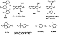 | ||
| Fig. 2 ChemDraw structures of the tin(II) complexes and organic azides employed in this study and their abbreviations. | ||
Results and discussion
Preparation, characterization, and crystal structures of tin(II) complexes
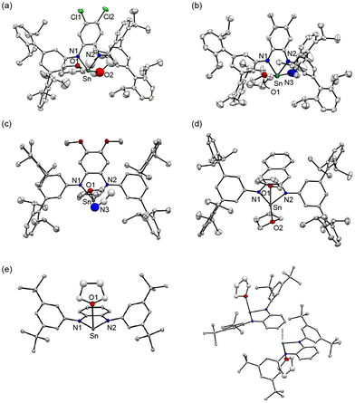
Tin(II) complexes Cl1, Me1, OMe1, naph1 and SnLPh(tBu)2 were synthesised by a ligand exchange reaction between Sn[N(SiMe3)2]2 and RLH2 (R = Cl, Me, OMe and naph) or LPh(tBu)2H2. The obtained complexes were characterised by 1H, 13C, and 119Sn NMR spectroscopy as well as elemental analysis. In the 1H NMR spectra of all the complexes in C6D6, 1H signals of all C–H protons of the ligands appeared but the N–H proton signals of RLH2 disappeared, indicating that isolated tin(II) complexes have the deprotonated diamido ligand, (RL)2− or (LPh(tBu)2)2−, as in the case of H1 (see Experimental section and Fig. S1–S4†).23 Single crystals of the tin(II) complexes were obtained by slow diffusion of acetonitrile into a THF solution of each complex. The ORTEP drawings of the X-ray crystal structures are depicted in Fig. 3. The crystal structures of Cl1, Me1, OMe1 and naph1 reveal that overall they all resemble that of H1 exhibiting a stannylene-type structure with the two coordinating nitrogen atoms of the diamido unit as previously reported (Fig. 3(a)–(d)). But there are some structural differences when compared with the structures of the related stannylene complexes coordinated with the less hindered o-phenylenediamido ligands reported in the literature.24–30 Namely, due to the sterically demanding TIPT substituents, there is no intermolecular interaction in the RL ligand system to allow coordination of two solvent molecules with each tin(II) centre. In Cl1 and naph1, the two apical positions are occupied with two THF molecules. With respect to Me1 and OMe1, one coordinating solvent molecule is THF while the other one is CH3CN. In the case of SnLPh(tBu)2, on the other hand, one of the apical positions is ligated with one THF molecule but the opposite apical site is occupied by the phenylenediamido ring of a neighboring tin(II) complex (Fig. 3(e)). The closest distance between the tin(II) centre and the aromatic ring of the neighboring complex is 2.85 Å, confirming an intermolecular interaction between the empty 5pz-orbital of tin(II) and a π-orbital of the phenylenediamido unit. Apparently, the sterically demanding TIPT substituent prohibits such an intermolecular interaction to stabilize the monomer structure of R1 as mentioned in the Introduction.The 119Sn NMR spectra of C6D6 solutions of Cl1, H1, Me1, OMe1 and naph1 were recorded to evaluate the coordination environments of the tin(II) centers (Fig. S5†). The 119Sn signals appeared at 26 ppm, 65 ppm, 83 ppm, 126 ppm and 54 ppm, respectively, which are listed in Table 1 together with those of the related stannylene complexes.24–30 It has been reported that a 119Sn chemical shift of stannylene is largely related to the coordination number of the tin center.29,48 The appearance of a 119Sn signal in a higher magnetic field region indicates the presence of a four-coordinate tin(II) complex, whereas a 119Sn signal appearing in a lower magnetic field region indicates formation of a two-coordinate tin(II) center.31,35 For example, two-coordinate monomeric stannylene, [Sn(C6H4(NMe)2)], existing in a diluted C6D6 solution, exhibits a 119Sn signal at 222 ppm.26 A tin(II) complex, [Sn(C6H4(NCH2Ch2OMe)2)], which exhibits a monomer structure with weak intramolecular interactions between the tin(II) centre and the two ether oxygen atoms of the ligand sidearm, shows a 119Sn signal at 148 ppm.26 On the other hand, a dimer complex, [Sn(C6H4(NCH2CH2CH2N(Me)2)2)]2, consisting of intramolecular Sn–NMe2 interactions and intermolecular Sn–N (phenylenediamido of a neighboring molecule) interactions, affords four-coordinated tin(II) centres, which show a 119Sn signal at 52 ppm.26 The 119Sn chemical shifts of the series of R1 complexes varied from 26 to 126 ppm. Since all the complexes adopt a four-coordinate monomer structure in the solid state as revealed by the crystallographic study (Fig. 3), the observed variation of the 119Sn chemical shift suggests involvement of an equilibrium between the three and/or four-coordinate structure and its two-coordinate one that is formed by dissociation of the coordinating solvent molecules, as shown in eqn (1):
 | (1) |
The 119Sn signal of Cl1 appeared at the highest magnetic field among the series of R1 complexes, suggesting that 2pz (2N of o-phenylenediamido) → 5pz (Sn) donation was weakened by the electron-withdrawing chloro-substituents, making dissociation of the coordinating solvent molecules from the tin(II) centre difficult in C6D6. Thus, the four-coordinate tin(II) centre in Cl1 is more stabilized. On the other hand, OMe1 had its 119Sn peak at the lowest magnetic field due to the electron-donating nature of the methoxy substituents, making the equilibrium proceed in the right-arrow direction of eqn (1). In fact, the 1H NMR spectrum of OMe1 in C6D6 showed 1H signals assignable to a free THF molecule (dissociated THF) in solution. Judging from the observed 119Sn chemical shifts, it can be concluded that the solvent-coordinated complexes are more stabilized as the substituent R goes from OMe, Me, H, naph and to Cl.
Effects of the bulky TIPT substituent on stability toward hydrolysis
As revealed by the crystal structure analysis of R1, the TIPT substituents effectively stabilise the monomer tin(II) structure and allow coordination of two solvent molecules. Since stannylene is known to undergo hydrolysis easily,31 the stability of H1 toward hydrolysis was compared to that of SnLPh(tBu)2 and SnLPh. Addition of a small amount of water to a THF solution of each complex resulted in the formation of original ligand precursors, HLH2 and a white powder of SnO according to eqn (2):
 | (2) |
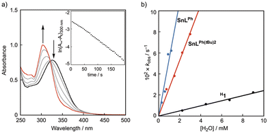
In Fig. 4(a), the spectral changes for the hydrolysis of H1 are shown. The absorption band of H1 at 330 nm decreases with the increasing absorption band at 300 nm due to the original ligand with an isosbestic point at 325 nm, obeying first-order kinetics (see inset of Fig. 4(a)). The pseudo-first-order rate constant (kobs, s−1) was proportional to the concentration of added water, as shown in Fig. 4(b), from which the second-order rate constant (k) was obtained as 2.4 M−1 s−1. The hydrolytic reactions of SnLPh(tBu)2 and SnLPh were analyzed in a similar manner to that of H1, and the second-order rate constants were determined as 26 M−1 s−1 and 54 M−1 s−1, respectively (Fig. 4(b)). The second-order rate constants of SnLPh(tBu)2 and SnLPh are larger by about 10 and 22 times, respectively, than that of H1, demonstrating that both of the bulky TIPT substituents and the coordinating solvent molecules suppress the attack of water molecules at the tin(II) centre.
Electrochemical properties of the tin(II) complexes
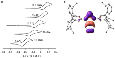
We recently reported electrochemical properties of H1 in THF, which was the first example of one of the tin(II) complexes with o-phenylenediamido ligands to be subjected to CV measurement.23 In this study, substituent effects of R1 on electrochemical properties of Cl1, Me1, OMe1, and naph1 were also examined. As shown in Fig. 5(a), a quasi-reversible redox wave was observed at +0.05 V, −0.10 V, −0.24 V, and −0.45 V vs. Fc/Fc+, respectively. naph1 also exhibited a quasi-reversible redox wave at +0.13 V vs. Fc/Fc+. Apparently, the oxidation potential of the tin(II) complexes shifts toward the negative direction as the electron-donating nature of the substituent of R1 increases from Cl, H, Me, to OMe. We have already demonstrated that one-electron oxidation of H1 takes place at the supporting ligand to generate the diiminosemiquinone radical complex of tin(II), R2.23 The observed substituent-dependent negative shift of the oxidation potential further supports this conclusion. Fig. 5(b) shows the HOMO diagram of H1 obtained by DFT calculations, where the majority of the HOMO exists on the phenylenediamido moiety. In both CVs of SnLPh(tBu)2 and SnLPh, irreversible oxidation waves were observed at Epa = −0.20 V and Epa = −0.17 V, respectively.Reactivity of the tin(II) complexes toward organic azides
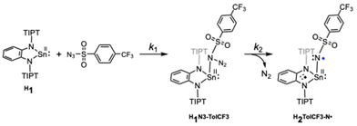
The reactivity of R1 complexes in a C–H amination reaction was examined using trisylazide (N3–Trs) as a substrate (Fig. 2 and Scheme 1). Following the reactions of OMe1, Me1 and H1, sultam (5,7-diisopropyl-2,3-dihydro-3,3-dimethyl-1,2-benzothiazole-1,1-dioxide) was obtained in 25, 23 and 22% yields, respectively. As a by-product, trisylamine was also obtained. However, sultam was not obtained from the reactions of trisylazide with Cl1 and naph1. Such a difference in the reactivity can be attributed to whether the nitrene-radical bound species, [Sn(RL)(Trs–N˙)] (R2Trs–N˙), is generated as the reactive oxidant by electron transfer from the o-phenylenediamido moiety to the bound N3-Trs and the successive release of dinitrogen (N2) (Scheme 2). In our previous paper, such a nitrene-radical bound species, R2Trs–N˙, has been revealed as the active oxidant for the intramolecular amination reaction to give sultam.23 In R2Trs–N˙, most of the spin is located on the nitrene nitrogen atom (the spin density = 82%) while the remainder is on the tin(II) center (2%) and on the sulfonyl group (–S(O)2–) (16%). Reactions of N3-Trs with tin(II) complexes with sterically less hindered ligands, SnLPh(tBu)2 and SnLPh, did not give sultam.Then, the reactivity of the tin(II) complexes toward organic azides was followed by UV-vis-NIR spectroscopy at low temperature. Since the nitrene-radical complex, H2Ns–N˙, has a diiminosemiquinone radical unit, which exhibits a broad absorption band (960 nm) in the near-IR region,23 formation of the analogues intermediate, R2R′-N˙, was examined in the reactions of the series of R1 complexes and organic azides (N3–R′) by monitoring the appearance of the broad absorption band in the near-IR region. Table S3† lists the λmax of the near-IR absorption bands of the generated R2R′–N˙. The absorption spectra of R2R′–N˙ are given in Fig. S6.† Complex OMe1 activated all organic azides employed, N3–R′, to produce a series of R2R′–N˙. Me1 gave Me2Ns–N˙, Me2TolCF3–N˙ and Me2Ts–N˙ from the reactions with the corresponding azides. Reactions of H1 with N3–Ns and N3–TolCF3 also afforded H2Ns–N˙ and H2TolCF3–N˙, respectively. Reactions of other combinations did not proceed. Thus, the reactivity of R1 toward organic azides, N3–R′, became higher as the oxidation potential became more negative: Cl → H → Me → OMe. Namely, OMe1 having the lowest oxidation potential exhibits the highest reactivity in the activation of organic azides. On the other hand, Cl1 and naph1 having higher oxidation potentials did not reduce the azides. IR spectra of the organic azides were recorded to observe the νN![[triple bond, length as m-dash]](https://www.rsc.org/images/entities/char_e002.gif) N stretch bands and their values are also listed in Table S3.† As is clearly seen, the higher the νN
N stretch bands and their values are also listed in Table S3.† As is clearly seen, the higher the νN![[triple bond, length as m-dash]](https://www.rsc.org/images/entities/char_e002.gif) N value, the easier the dinitrogen release.
N value, the easier the dinitrogen release.
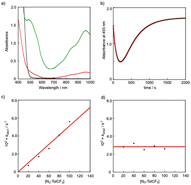
It is proposed that generation of a nitrene bound metal complex R2R′–N˙ from the precursor complex R1 and an organic azide N3–R′ requires the following two steps: (1) coordination of an organic azide to the precursor complex to yield an adduct complex and (2) elimination of a dinitrogen molecule (N2) from the adduct complex. A large number of nitrene bound metal complexes including metal imido and metal nitrene-radical complexes have so far been prepared by such reactions. However, no kinetics study on such a two-step process has been reported. By careful inspection of the absorption spectral change of R1 observed upon addition of N3–R′, we found that the reaction of H1 with N3–TolCF3 giving H2TolCF3–N˙ consisted of two-step processes. Fig. 6(a) shows spectral changes for the reaction of H1 (1.0 mM) in the presence of N3–TolCF3 (20.0 mM) in toluene at −40 °C. The original spectrum (black line) of H1 readily changed to the red line spectrum, and then the characteristic absorption bands at 490, 880, and 965 nm due to the nitrene-radical bound complex, H2TolCF3–N˙, gradually appeared (green line spectrum) (Fig. S7†). The time course of the absorbance changes at 455 nm was fitted by using eqn (3), from which the apparent rate constants for the first step, kobs1 (s−1), and the second step, kobs2 (s−1), were obtained (Fig. 6(b)):
| Abs455 = a + b·exp(−kobs1·t) − c·exp(−kobs2·t) | (3) |
As shown in Fig. 6(c) and (d), kobs1 (s−1) was proportional to the concentration of N3–TolCF3, whereas kobs2 (s−1) was independent of N3–TolCF3 concentration, from which the second-order rate constant k1 and the first-order rate constant k2 were determined as being 0.19 M−1 s−1 and 5 × 10⁻³ s−1, respectively (the time courses of the absorbance changes at each concentration of N3–TolCF3 are given in Fig. S8†). The first step is safely assigned to that involving coordination of N3–TolCF3 to H1 to yield an intermediate H1N3–TolCF3, while the second step involves N2 elimination from H1N3–TolCF3 coupled with a one-electron transfer from the phenylenediamido moiety to the azide moiety to give H2TolCF3–N˙ (Scheme 2). On the other hand, when OMe1 was employed instead of H1, the UV-vis spectrum of OMe1 was directly changed to that of OMe2TolCF3–N˙ following a single exponential kinetics equation, namely the adduct intermediate was not detected spectroscopically (Fig. S9†). Such a difference in the kinetics behaviors can be explained as follows. The oxidation potential of H1 is higher than that of OMe1. Thus, the intramolecular electron transfer from the phenylenediamido unit to the coordinating azide in H1N3–TolCF3 must be slower than that in the methoxy analogue OMe1N3–TolCF3. Accordingly, the first step for adduct formation of N3–TolCF3 and H1 was observable. On the other hand, intramolecular electron transfer within OMe1N3–TolCF3 to produce OMe2TolCF3–N˙ will be much faster than that within H1N3–TolCF3 taking the lower oxidation potential of OMe1 into account. Moreover, the tin(II) centre of OMe1 favors the two-coordinate structure as revealed by the 119Sn NMR spectral examination (Table 1), where the initial association process between OMe1 and N3–TolCF3, namely coordination of N3–TolCF3 to OMe1, becomes unfavorable (slower) when compared with the case of H1.
The formation mechanism of H2TolCF3–N˙ deduced by the kinetics study is further supported by DFT calculations. The majority of the LUMO of H1 comprises the 5pz orbital of the tin(II) centre as shown in Fig. S10,† which accepts coordination of N3–TolCF3 to yield the adduct complex, H1N3–TolCF3. This complex adopts the closed-shell singlet state (CSS), where the phenylenediamido unit constitutes the HOMO whereas the N3–TolCF3 part significantly contributes to the LUMO (Fig. 7). The energy difference between the HOMO and LUMO of H1N3–TolCF3 is 2.41 eV. In the conversion of H1N3–TolCF3 to H2TolCF3–N˙, the transition state (TS) is also a CSS, which is formed with Ea = 10.5 kcal mol−1. Two electrons in the HOMO of the TS delocalize over the phenylenediamido and N3–S(O)2– units excluding the sulfur and tin atoms and similarly in the LUMO there are contributions from the two units. Following the dinitrogen elimination with ΔE = −16.0 kcal mol−1, a triplet state is generated in the nitrene-radical bound complex H2TolCF3–N˙ having a triplet state is generated.
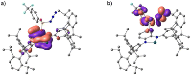 | ||
| Fig. 7 (a) Frontier Kohn–Sham orbitals of the HOMO (a) and the LUMO (b) for H1N3–TolCF3 (B3LYP/SDD (for Sn), D95** (for the other atoms)). | ||
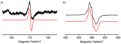
To confirm that H2TolCF3–N˙ is a triplet species, its X-band electron paramagnetic resonance (EPR) spectrum was recorded in toluene glass at 4.1 K (Fig. 8). As observed in H2Ns–N˙, which was recently reported,23 the half-field transition for ΔMS = ±2 was observed at g ∼ 4 together with allowed transitions for ΔMS = ±1, demonstrating that H2TolCF3–N˙ also includes a spin-triplet species. By simulating the observed spectra using the Easyspin toolbox40 on MATLAB software, we determined magnetic parameters of H2N˙–TolCF3 as follows: gxx = 2.001, gyy = 1.998, gzz = 2.000, |D| = 0.0039 cm−1, and |E| = 0.0005 cm−1. The signal intensities of the half-field transitions were not proportional to 1/T, indicating that the spin-triplet species is in a thermally excited state (Fig. S11†). Thus, this triplet species was characterised as a tin(II)–nitrene-radical complex with a diiminobenzosemiquinone radical anion, H2TolCF3–N˙.
Conclusions
In this manuscript, tin(II) complexes with o-phenylenediamido ligands that have a terphenyl-based sterically bulky substituent were synthesised and then characterised by several spectroscopic methods. Crystal structures of all complexes were determined and these show tin(II) centres that adopt a four-coordinate structure with two amido nitrogen atoms of the o-phenylenediamido ligand and two solvent molecules. Following 119Sn NMR study of the complexes in C6D6, each tin(II) center was revealed to exist in equilibrium between the four-coordinate tin(II) centre and the two-coordinate version formed by dissociation of the two solvent ligands, where ligands having electron-donating groups stabilised the two-coordinate tin(II) centre while those having electron-withdrawing groups stabilised the four-coordinate species. The terphenyl-based bulky substituent stabilised the tin(II) centre against hydrolysis, which was demonstrated by comparing its stability with that of the tin(II) complexes with less bulky substituents. The tin(II) complexes with sterically demanding o-phenylenediamido-based ligand derivatives underwent ligand-based redox and the oxidation potential varied from −0.45 V to +0.13 V as the substituent goes from –OMe to –naph. The tin(II) complexes having electron-donating groups exhibited intramolecular C–H amination of trisylazide to give sultam but the amination product was not obtained by the reactions of those complexes having electron-withdrawing groups with this substrate. Such a difference in the reactivity was the availability of the nitrene-radical bound tin(II) reactive intermediate. A step of binding an organic azide to a tin(II) complex and then successive one-electron transfer steps from the ligand to the bound azide moiety to give the nitrene radical tin(II) complex were analyzed kinetically. The combination of the o-phenylenediamido ligands and a tin(II) centre provides further insights into the roles of redox-active ligands in the reactions of main group element complexes.Experimental
Materials and methods
General
Reagents and solvents used in this study except for the ligand and complexes were commercial products of the highest available purity. The solvents were stored with a molecular sieve 4A. Silica gel 60 (0.063–0.200 mm) made by Merck was used for silica gel column chromatography. Sn[N(SiMe3)2]2,36 [Sn(LPh)]29 and [Sn(HLTIPT)] (H1)23 were prepared according to reported methods under argon in a Miwa DB0-1KP glovebox. LPh(tBu)2H2,15 5′-bromo-2,4,2′′,4′′-tetraisopropyl-[1,1′:3′,1′′]terphenyl (TIPT-Br),23 4,5-dimethoxyphenylene-1,2-diamine,37 4-methylbenzenesulfonyl azide (N3–Ts),38 4-nitrobenzenesulfonyl azide (N3–Ns),38 4-(trifluoromethyl)benzenesulfonyl azide (N3–TolCF3),39 2,4,6-trimethylphenylazide (N3–Mes),40 1-azido-4-nitrobenzene (N3–PhNO2)40 and mestylazide41 were synthesised by following the reported methods. EPR measurements were carried out on a BRUKER ELEXSYS E600 spectrometer under non-saturating microwave power conditions. UV-vis spectra were recorded on a Hewlett Packard 8453 photo-diode array spectrophotometer equipped with a UNISOK thermostated cell holder (USP-203). Solution IR spectra were acquired on a SHIMAZU spectrometer (IRPrestige-21). 1H, 13C and 119Sn NMR spectra were recorded on a JEOL ECP 400 or a JEOL ECS 400 spectrometer. Elemental analysis and HR-MS measurements were conducted in the Analytical Instrumentation Center of the Graduate School of Engineering, Osaka University. Electrochemical measurements were performed using a KOREA KIYON KK-011AS glovebox with a Hokuto Denko HZ-7000 in THF (1.0 mM) containing nBu4NPF6 (0.1 M) at room temperature. A set of a carbon working electrode (diameter = 3 mm), an Ag/AgNO3/CH3CN reference electrode and a platinum counter electrode was employed in these experiments. All redox potentials are referenced to the ferrocene/ferrocenium (Fc/Fc+) redox potential. The values of E1/2 and Δ(Epa − Epc) vs. Ag/AgNO3 from the cyclic voltammogram of Fc were 0.30 V and 0.20 V, respectively, under the employed conditions.![[thin space (1/6-em)]](https://www.rsc.org/images/entities/char_2009.gif) :
:![[thin space (1/6-em)]](https://www.rsc.org/images/entities/char_2009.gif) 1) as an eluent. A pale-yellow band was collected and evaporated to give a white solid of ClLTIPTH2 (891 mg, 46%), which was recrystallized by slow diffusion of acetonitrile into a THF solution. Anal. calcd (%) for C66H76Cl2N2·0.3THF: C, 81.37; H, 8.17; N, 2.82. Found: C, 81.42; H, 8.10; N, 2.84. 1H NMR (CDCl3, 600 MHz, ppm): δ = 7.41 (s, 2H, HArN2), 7.32 (t, J = 7.8 Hz, 4H, HTIPT), 7.18 (d, J = 7.8 Hz, 8H, HTIPT), 6.83 (d, J = 1.2 Hz, 4H, HTIPT), 6.64 (t, J = 1.2 Hz, 2H, HTIPT), 5.69 (s, 2H, HNH), 2.81 (sep, J = 7.2 Hz, 8H, HCH(iPr)), 1.17 (d, J = 7.2 Hz, 24H, HMe(iPr)), 1.08 (d, 7.2 Hz, 24H, HMe(iPr)). 13C NMR (CDCl3, 600 MHz, ppm): δ = 146.57, 142.00, 138.68, 134.60, 127.90, 125.04, 124.88, 122.50, 119.58, 117.53, 30.46, 24.40, 24.19 (Fig. S1†). HR-MS (FAB+): m/z = 968.5540.
1) as an eluent. A pale-yellow band was collected and evaporated to give a white solid of ClLTIPTH2 (891 mg, 46%), which was recrystallized by slow diffusion of acetonitrile into a THF solution. Anal. calcd (%) for C66H76Cl2N2·0.3THF: C, 81.37; H, 8.17; N, 2.82. Found: C, 81.42; H, 8.10; N, 2.84. 1H NMR (CDCl3, 600 MHz, ppm): δ = 7.41 (s, 2H, HArN2), 7.32 (t, J = 7.8 Hz, 4H, HTIPT), 7.18 (d, J = 7.8 Hz, 8H, HTIPT), 6.83 (d, J = 1.2 Hz, 4H, HTIPT), 6.64 (t, J = 1.2 Hz, 2H, HTIPT), 5.69 (s, 2H, HNH), 2.81 (sep, J = 7.2 Hz, 8H, HCH(iPr)), 1.17 (d, J = 7.2 Hz, 24H, HMe(iPr)), 1.08 (d, 7.2 Hz, 24H, HMe(iPr)). 13C NMR (CDCl3, 600 MHz, ppm): δ = 146.57, 142.00, 138.68, 134.60, 127.90, 125.04, 124.88, 122.50, 119.58, 117.53, 30.46, 24.40, 24.19 (Fig. S1†). HR-MS (FAB+): m/z = 968.5540.![[thin space (1/6-em)]](https://www.rsc.org/images/entities/char_2009.gif) :
:![[thin space (1/6-em)]](https://www.rsc.org/images/entities/char_2009.gif) 1) as an eluent. MeLH2 was recrystallized by slow diffusion of acetonitrile into a THF solution. Anal. calcd (%) for C68H82N2·0.3THF: C, 87.39; H, 9.16; N, 2.95. Found: C, 87.34; H, 9.17; N, 2.95. 1H NMR (CDCl3, 600 MHz, ppm): δ = 7.30 (t, J = 7.2 Hz, 4H, HTIPT), 7.19 (s, 2H, HArN2), 7.17 (d, J = 7.2 Hz, 8H, HTIPT), 6.77 (d, J = 1.8 Hz, 4H, HTIPT), 6.51 (t, J = 1.2 Hz, 2H, HTIPT), 5.62 (s, 2H, HNH), 2.85 (sep, J = 7.2 Hz, 8H, HCH(iPr)), 1.16 (d, J = 7.2 Hz, 24H, HMe(iPr)), 1.07 (d, 7.2 Hz, 24H, HMe(iPr)). 13C NMR (CDCl3, 600 MHz, ppm): δ = 146.63, 143.78, 141.48, 139.24, 132.36, 130.84, 127.67, 123.14, 122.41, 121.04, 116.16, 30.37, 24.43, 24.20, 19.26 (Fig. S2†). HR-MS (FAB+): m/z = 928.6641.
1) as an eluent. MeLH2 was recrystallized by slow diffusion of acetonitrile into a THF solution. Anal. calcd (%) for C68H82N2·0.3THF: C, 87.39; H, 9.16; N, 2.95. Found: C, 87.34; H, 9.17; N, 2.95. 1H NMR (CDCl3, 600 MHz, ppm): δ = 7.30 (t, J = 7.2 Hz, 4H, HTIPT), 7.19 (s, 2H, HArN2), 7.17 (d, J = 7.2 Hz, 8H, HTIPT), 6.77 (d, J = 1.8 Hz, 4H, HTIPT), 6.51 (t, J = 1.2 Hz, 2H, HTIPT), 5.62 (s, 2H, HNH), 2.85 (sep, J = 7.2 Hz, 8H, HCH(iPr)), 1.16 (d, J = 7.2 Hz, 24H, HMe(iPr)), 1.07 (d, 7.2 Hz, 24H, HMe(iPr)). 13C NMR (CDCl3, 600 MHz, ppm): δ = 146.63, 143.78, 141.48, 139.24, 132.36, 130.84, 127.67, 123.14, 122.41, 121.04, 116.16, 30.37, 24.43, 24.20, 19.26 (Fig. S2†). HR-MS (FAB+): m/z = 928.6641.![[thin space (1/6-em)]](https://www.rsc.org/images/entities/char_2009.gif) :
:![[thin space (1/6-em)]](https://www.rsc.org/images/entities/char_2009.gif) 2) as an eluent. The obtained solid was washed with acetonitrile to give a white solid of OMeLH2 (0.58 g, 40%). Anal. calcd (%) for C68H84N2O2·2.5H2O: C, 81.14; H, 8.91; N, 2.78. Found: C, 81.14; H, 8.60; N, 2.85. 1H NMR (CDCl3, 400 MHz, ppm): δ = 7.30 (t, 4H, HTIPT), 7.16 (d, 8H, HTIPT), 6.93 (s, 2H, HArN2), 6.69 (d, J = 1.2, 2H, HTIPT), 6.50 (t, J = 1.2 Hz, 4H, HTIPT), 5.63 (s, 2H, HNH), 3.75 (s, 6H, HOMe), 2.82 (sept, J = 6.6 Hz, 8H, HCH(iPr)), 1.12 (d, J = 6.6 Hz, 24H, HMe(iPr)), 1.05 (d, J = 6.6 Hz, 24H, HMe(iPr)). 13C NMR (CDCl3, 600 MHz, ppm): δ = 146.54, 145.39, 144.30, 141.58, 139.21, 128.22, 127.72, 123.24, 122.42, 115.48, 106.48, 56.37, 30.34, 24.44, 24.14 (Fig. S3†). HR-MS (FAB+): m/z = 960.6554.
2) as an eluent. The obtained solid was washed with acetonitrile to give a white solid of OMeLH2 (0.58 g, 40%). Anal. calcd (%) for C68H84N2O2·2.5H2O: C, 81.14; H, 8.91; N, 2.78. Found: C, 81.14; H, 8.60; N, 2.85. 1H NMR (CDCl3, 400 MHz, ppm): δ = 7.30 (t, 4H, HTIPT), 7.16 (d, 8H, HTIPT), 6.93 (s, 2H, HArN2), 6.69 (d, J = 1.2, 2H, HTIPT), 6.50 (t, J = 1.2 Hz, 4H, HTIPT), 5.63 (s, 2H, HNH), 3.75 (s, 6H, HOMe), 2.82 (sept, J = 6.6 Hz, 8H, HCH(iPr)), 1.12 (d, J = 6.6 Hz, 24H, HMe(iPr)), 1.05 (d, J = 6.6 Hz, 24H, HMe(iPr)). 13C NMR (CDCl3, 600 MHz, ppm): δ = 146.54, 145.39, 144.30, 141.58, 139.21, 128.22, 127.72, 123.24, 122.42, 115.48, 106.48, 56.37, 30.34, 24.44, 24.14 (Fig. S3†). HR-MS (FAB+): m/z = 960.6554.![[thin space (1/6-em)]](https://www.rsc.org/images/entities/char_2009.gif) :
:![[thin space (1/6-em)]](https://www.rsc.org/images/entities/char_2009.gif) 1) as an eluent, which was washed with acetonitrile to give a white solid of naphLH2 (0.78 g, 55%). Anal. calcd (%) for C70H82N2: C, 88.37; H, 8.69; N, 2.94. Found: C, 88.22; H, 8.85; N, 2.90. 1H NMR (CDCl3, 400 MHz, ppm): δ = 7.77 (s, 2H, HArN2), 7.48 (m, 2H, HArN2), 7.32 (t, J = 7.6 Hz, 4H, HTIPT), 7.23 (m, 2H, HArN2), 7.20 (d, J = 7.6 Hz, 8H, HTIPT), 6.98 (d, J = 1.2, 4H, HTIPT), 6.30 (t, J = 1.2 2H, HTIPT), 5.92 (s, 2H, HNH), 2.88 (sep, J = 6.8 Hz, 8H, HCH(iPr)), 1.20 (d, J = 6.8 Hz, 24H, HMe(iPr)), 1.10 (d, J = 6.8 Hz, 24H, HMe(iPr)). 13C NMR (CDCl3, 600 MHz, ppm): δ = 146.60, 142.71, 141.80, 138.96, 135.09, 129.96, 127.81, 126.12, 124.42, 124.36, 122.47, 117.53, 113.67, 30.45, 24.43, 24.24 (Fig. S4†). HR-MS (FAB+): m/z = 950.6500.
1) as an eluent, which was washed with acetonitrile to give a white solid of naphLH2 (0.78 g, 55%). Anal. calcd (%) for C70H82N2: C, 88.37; H, 8.69; N, 2.94. Found: C, 88.22; H, 8.85; N, 2.90. 1H NMR (CDCl3, 400 MHz, ppm): δ = 7.77 (s, 2H, HArN2), 7.48 (m, 2H, HArN2), 7.32 (t, J = 7.6 Hz, 4H, HTIPT), 7.23 (m, 2H, HArN2), 7.20 (d, J = 7.6 Hz, 8H, HTIPT), 6.98 (d, J = 1.2, 4H, HTIPT), 6.30 (t, J = 1.2 2H, HTIPT), 5.92 (s, 2H, HNH), 2.88 (sep, J = 6.8 Hz, 8H, HCH(iPr)), 1.20 (d, J = 6.8 Hz, 24H, HMe(iPr)), 1.10 (d, J = 6.8 Hz, 24H, HMe(iPr)). 13C NMR (CDCl3, 600 MHz, ppm): δ = 146.60, 142.71, 141.80, 138.96, 135.09, 129.96, 127.81, 126.12, 124.42, 124.36, 122.47, 117.53, 113.67, 30.45, 24.43, 24.24 (Fig. S4†). HR-MS (FAB+): m/z = 950.6500.Kinetics study on the formation of tin–nitrenoid complexes
A toluene solution of H1 (1.0 mM, 2.0 mL) in a 1.0 cm path-length UV-vis cuvette was held in a Unisoku thermostated cell holder at −40 °C. An aliquot (20 μL) of a toluene solution of N3–TolCF3 (1.0 g, 4.0 mmol in 1.0 mL) was added to the toluene solution of H1 in the cuvette through a septum cap by using a gas-tight syringe to start the reaction. In this case, the molar ratio of H1 and N3–TolCF3 was 1![[thin space (1/6-em)]](https://www.rsc.org/images/entities/char_2009.gif) :
:![[thin space (1/6-em)]](https://www.rsc.org/images/entities/char_2009.gif) 20. The same procedures were repeated by changing the amount of added N3–TolCF3 (40, 60, 80, and 100 equiv. against H1). The reaction consisted of a two-step process: H1 + N3–TolCF3 → [H1N3–TolCF3] → H2TolCF3–N˙. The time course of the absorbance changes at 455 nm due to the H1N3–TolCF3 adduct intermediate was fitted by the following equation: Abs. = a + b·exp(–kobs1·t) + c·exp(–kobs2·t) to give rate constants, where the apparent rate constants, kobs(1) (s−1) and kobs(2) (s−1), correspond to the first step and the second step, respectively.
20. The same procedures were repeated by changing the amount of added N3–TolCF3 (40, 60, 80, and 100 equiv. against H1). The reaction consisted of a two-step process: H1 + N3–TolCF3 → [H1N3–TolCF3] → H2TolCF3–N˙. The time course of the absorbance changes at 455 nm due to the H1N3–TolCF3 adduct intermediate was fitted by the following equation: Abs. = a + b·exp(–kobs1·t) + c·exp(–kobs2·t) to give rate constants, where the apparent rate constants, kobs(1) (s−1) and kobs(2) (s−1), correspond to the first step and the second step, respectively.
EPR measurement
An EPR sample tube (ϕ = 5 mm) containing a toluene solution (0.8 mL) of H1 (1.0 mM) was cooled and kept at −40 °C with a dry ice-CH3CN bath. To the toluene solution, a toluene solution of N3–TolCF3 was added through a septum cap by using a gas-tight syringe ([1]![[thin space (1/6-em)]](https://www.rsc.org/images/entities/char_2009.gif) :
:![[thin space (1/6-em)]](https://www.rsc.org/images/entities/char_2009.gif) [N3–TolCF3] = 1
[N3–TolCF3] = 1![[thin space (1/6-em)]](https://www.rsc.org/images/entities/char_2009.gif) :
:![[thin space (1/6-em)]](https://www.rsc.org/images/entities/char_2009.gif) 1). After standing at −40 °C for 1 h to generate H2TolCF3–N˙, the solution was frozen in liquid nitrogen. EPR spectra of the frozen solution were observed with an X-band ELEXSYS E600 EPR spectrometer (νMW = 9.5375 GHz) at liquid helium temperature. Microwave power of 0.01 mW and modulation amplitude of 0.1 mT were applied for the measurements of allowed transitions. On the other hand, microwave power of 1.0 mW and modulation amplitude of 1 mT were applied for the measurements of half-field forbidden transitions. The spectrum measured was simulated by the Easyspin toolbox.42
1). After standing at −40 °C for 1 h to generate H2TolCF3–N˙, the solution was frozen in liquid nitrogen. EPR spectra of the frozen solution were observed with an X-band ELEXSYS E600 EPR spectrometer (νMW = 9.5375 GHz) at liquid helium temperature. Microwave power of 0.01 mW and modulation amplitude of 0.1 mT were applied for the measurements of allowed transitions. On the other hand, microwave power of 1.0 mW and modulation amplitude of 1 mT were applied for the measurements of half-field forbidden transitions. The spectrum measured was simulated by the Easyspin toolbox.42
Intramolecular amination of trisylazide (N3–Trs)
Trisylazide (35 μmol, 10.9 mg) was dissolved in toluene (1.0 mL) and then an aliquot (20 μL) of the solution was added to a toluene solution (1.0 mL) of R1 (3.50 μmol), where the ratio of trisylazide![[thin space (1/6-em)]](https://www.rsc.org/images/entities/char_2009.gif) :
:![[thin space (1/6-em)]](https://www.rsc.org/images/entities/char_2009.gif) R1 is 1
R1 is 1![[thin space (1/6-em)]](https://www.rsc.org/images/entities/char_2009.gif) :
:![[thin space (1/6-em)]](https://www.rsc.org/images/entities/char_2009.gif) 1. The mixture was stirred at 70 °C for 24 h under argon. All volatiles were evaporated in vacuo and the crude products were analyzed by 1H NMR spectroscopy (CDCl3, 400 MHz; internal standard: 1,4-dimethoxybenzene (2.07 mg, 15.0 μmol)). The aminated product (sultam: 5,7-di-isopropyl-2,3-dihydro-3,3-dimethyl-1,2-benzothiazole-1,1-dioxide) was identified by comparing its 1H NMR chemical shifts with those of the authentic sample.
1. The mixture was stirred at 70 °C for 24 h under argon. All volatiles were evaporated in vacuo and the crude products were analyzed by 1H NMR spectroscopy (CDCl3, 400 MHz; internal standard: 1,4-dimethoxybenzene (2.07 mg, 15.0 μmol)). The aminated product (sultam: 5,7-di-isopropyl-2,3-dihydro-3,3-dimethyl-1,2-benzothiazole-1,1-dioxide) was identified by comparing its 1H NMR chemical shifts with those of the authentic sample.
Author contributions
H.S. conceived the idea and designed the project, and H.S. discussed all experimental results. A.Y. and M.Y. performed most of the experiments. K.S. contributed to EPR measurements and the analysis. Y.S., M.M. and K.Y. performed theoretical calculations. S.I. was involved in the discussion of experimental results. H.S. and S.I. wrote the manuscript. All the authors commented on the final draft of the manuscript and contributed to the analysis and interpretation of the data.Data availability
All relevant data are within the manuscript and its ESI.†Conflicts of interest
There are no conflicts to declare.Acknowledgements
This work was supported by KAKENHI (Grant-in-Aid) for Scientific Research (No. 23K04767).References
- V. K. K. Praneeth, M. R. Ringenberg and T. R. Ward, Angew. Chem., Int. Ed., 2012, 51, 10228–10234 CrossRef CAS PubMed.
- O. R. Luca and R. H. Crabtree, Chem. Soc. Rev., 2013, 42, 1440–1459 RSC.
- J. I. van der Vlugt, Chem. – Eur. J., 2019, 25, 2651–2662 CrossRef CAS PubMed.
- K. Singh, A. Kundu and D. Adhikari, ACS Catal., 2022, 12, 13075–13107 CrossRef CAS.
- Y. Umena, K. Kawakami, J. R. Shen and N. Kamiya, Nature, 2011, 473, 55–60 CrossRef CAS PubMed.
- N. Ito, S. E. V. Phillips, C. Stevens, Z. B. Ogel, M. J. McPherson, J. N. Keen, K. D. S. Yadav and P. F. Knowles, Nature, 1991, 350, 87–90 CrossRef CAS PubMed.
- J. Rittl and M. T. Green, Science, 2010, 330, 933–937 CrossRef PubMed.
- H. Schindelin, C. Kisker, J. Hilton, K. V. Rajagopalan and D. C. Rees, Science, 1996, 272, 1615–1621 CrossRef CAS PubMed.
- P. J. Chirik and K. Wieghardt, Science, 2010, 327, 794–795 CrossRef CAS PubMed.
- A. I. O. Suarez, V. Lyaskovskyy, J. N. H. Reek, J. I. van der Vlugt and B. de Bruin, Angew. Chem., Int. Ed., 2013, 52, 12510–12529 CrossRef CAS PubMed.
- D. L. J. Broere, B. de Bruin, J. N. H. Reek, M. Lutz, S. Dechert and J. I. van der Vlugt, J. Am. Chem. Soc., 2014, 136, 11574–11577 CrossRef CAS PubMed.
- D. L. J. Broere, N. P. van Leest, B. de Bruin, M. A. Siegler and J. I. van der Vlugt, Inorg. Chem., 2016, 55, 8603–8611 CrossRef CAS PubMed.
- D. Fujita, H. Sugimoto, Y. Shiota, Y. Morimoto, K. Yoshizawa and S. Itoh, Chem. Commun., 2017, 53, 4849–4852 RSC.
- D. Fujita, H. Sugimoto, Y. Morimoto and S. Itoh, Inorg. Chem., 2018, 57, 9738–9747 CrossRef CAS PubMed.
- D. Fujita, A. Kaga, H. Sugimoto, Y. Morimoto and S. Itoh, Bull. Chem. Soc. Jpn., 2019, 93, 279–286 CrossRef.
- Y. Ren, K. Cheaib, J. Jacquet, H. Vezin, L. Fensterbank, M. Orio, S. Blanchard and M. M. Desage-El, Chem. – Eur. J., 2018, 24, 5086–5890 CrossRef CAS PubMed.
- N. P. van Leest, M. A. Tepaske, J.-P. H. Oudsen, B. Venderbosch, N. R. Rietdijk, M. A. Siegler, M. Tromp, J. I. van der Vlugt and B. de Bruin, J. Am. Chem. Soc., 2020, 142, 552–553 CrossRef CAS PubMed.
- N. P. van Leest, M. A. Tepaske, B. Venderbosch, J.-P. H. Oudsen, M. Tromp, J. I. van der Vlugt and B. de Bruin, ACS Catal., 2020, 10, 7449–7463 CrossRef CAS PubMed.
- N. P. van Leest, J. I. van der Vlugt and B. de Bruin, Chem. – Eur. J., 2021, 27, 371–378 CrossRef CAS PubMed.
- N. P. van Leest and B. de Bruin, Inorg. Chem., 2021, 60, 8380–8387 CrossRef CAS PubMed.
- M. G. Chegerev, A. V. Piskunov, A. A. Starikova, S. P. Kubrin, G. K. Fukin, V. K. Cherkasov and G. A. Abakumov, Eur. J. Inorg. Chem., 2018, 2018, 1087–1092 CrossRef CAS.
- G. C. Briand, Dalton Trans., 2023, 52, 17666–17678 RSC.
- H. Sugimoto, M. Yano, K. Sato, M. Miyanishi, K. Sugisaki, Y. Shiota, A. Kaga, K. Yoshizawa and S. Itoh, Inorg. Chem., 2021, 60, 18603–18607 CrossRef CAS PubMed.
- H. Braunschweig, B. Gehrhus, P. B. Hitchcock and M. F. Lappert, Z. Anorg. Allg. Chem., 1995, 621, 1922–1928 CrossRef CAS.
- F. E. Hahn, L. Wittenbecher, M. Kühn, T. Lügger and R. A. Fröhlich, J. Organomet. Chem., 2001, 617–618, 629–634 CrossRef CAS.
- F. E. Hahn, L. Wittenbecher, L. D. Van and A. V. Zabula, Inorg. Chem., 2007, 46, 7662–7667 CrossRef CAS PubMed.
- J. V. Dickschat, S. Urban, T. Pape, F. Glorius and F. E. Hahn, Dalton Trans., 2010, 39, 11519–11521 RSC.
- M. M. Huang, M. M. Kireenko, E. K. Lermontova, A. V. Churakov, Y. F. Oprunenko, K. V. Zaitsev, D. Sorokin, K. Harms, J. Sundermeyer, G. S. Zaitseva and S. S. Karlov, Z. Anorg. Allg. Chem., 2013, 639, 502–511 CrossRef CAS.
- S. Krupski, R. Pöttgen, I. Schellenberg and F. E. Hahn, Dalton Trans., 2014, 43, 173–181 RSC.
- J. Brugos, J. A. Cabeza, P. García-Álvarez, E. Pérez-Carreño and D. Polo, Dalton Trans., 2018, 47, 4534–4544 RSC.
- Y. Mizuhata, T. Sasamori and N. Tokitoh, Chem. Rev., 2009, 109, 3479–3511 CrossRef CAS PubMed.
- K. Goto, G. Yamamoto, B. Tan and R. Okazaki, Tetrahedron Lett., 2001, 42, 4875–4877 CrossRef CAS.
- S. Paria, T. Ohta, Y. Morimoto, T. Ogura, H. Sugimoto, N. Fujieda, K. Goto, K. Asano, T. Suzuki and S. Itoh, J. Am. Chem. Soc., 2015, 137, 10870–10873 CrossRef CAS PubMed.
- D. V. Yandulov and R. R. Schrock, Science, 2003, 301, 76–78 CrossRef CAS PubMed.
- R. Hani and R. A. Geanangel, Coord. Chem. Rev., 1982, 44, 229–246 CrossRef CAS.
- T. Heidemann and S. Mathur, Eur. J. Inorg. Chem., 2014, 2014, 506–510 CrossRef CAS.
- Z. Qianqian, X. Bo, D. Mengzhen, L. Gongqiang, T. Ailing and Z. Erjun, J. Mater. Chem. C, 2018, 6, 10902–10909 RSC.
- A. K. Dhiman, S. Gupta, R. Sharma, R. Kumar and U. Sharma, J. Org. Chem., 2019, 84, 12871–12880 CrossRef CAS PubMed.
- S.-H. Hwang, H. Kim, H. Ryu, I. E. Serdiuk, D. Lee and T.-L. Choi, J. Am. Chem. Soc., 2022, 144, 1778–1785 CrossRef CAS PubMed.
- J. V. Ruppel, R. M. Kamble and X. P. Zhang, Org. Lett., 2007, 9, 4889–4892 CrossRef CAS PubMed.
- F. Sebest, L. Casarrubios, H. S. Rzepa, A. J. P. White and S. Díez-González, Green Chem., 2018, 20, 4023–4035 RSC.
- S. Stol and A. Schweiger, J. Magn. Reson., 2006, 178, 42–55 CrossRef PubMed.
- G. Sheldrick, Acta Crystallogr., Sect. A: Found. Adv., 2015, 71, 3–8 CrossRef PubMed.
- O. V. Dolomanov, L. J. Bourhis, R. J. Gildea, J. A. K. Howard and H. Puschmann, J. Appl. Crystallogr., 2009, 42, 339–341 CrossRef CAS.
- M. J. Frisch, G. W. Trucks, H. B. Schlegel, G. E. Scuseria, M. A. Robb, J. R. Cheeseman, G. Scalmani, V. Barone, G. A. Petersson, H. Nakatsuji, X. Li, M. Caricato, A. V. Marenich, J. Bloino, B. G. Janesko, R. Gomperts, B. Mennucci, H. P. Hratchian, J. V. Ortiz, A. F. Izmaylov, J. L. Sonnenberg, D. Williams-Young, F. Ding, F. Lipparini, F. Egidi, J. Goings, B. Peng, A. Petrone, T. Henderson, D. Ranasinghe, V. G. Zakrzewski, J. Gao, N. Rega, G. Zheng, W. Liang, M. Hada, M. Ehara, K. Toyota, R. Fukuda, J. Hasegawa, M. Ishida, T. Nakajima, Y. Honda, O. Kitao, H. Nakai, T. Vreven, K. Throssell, J. A. Montgomery Jr., J. E. Peralta, F. Ogliaro, M. J. Bearpark, J. J. Heyd, E. N. Brothers, K. N. Kudin, V. N. Staroverov, T. A. Keith, R. Kobayashi, J. Normand, K. Raghavachari, A. P. Rendell, J. C. Burant, S. S. Iyengar, J. Tomasi, M. Cossi, J. M. Millam, M. Klene, C. Adamo, R. Cammi, J. W. Ochterski, R. L. Martin, K. Morokuma, O. Farkas, J. B. Foresman and D. J. Fox, Gaussian 16, Revision A. 03, Gaussian, Inc., Wallingford, CT, 2016 Search PubMed.
- A. D. Becke, J. Chem. Phys., 1993, 98, 5648–5652 CrossRef CAS.
- C. Lee, W. Yang and R. G. Parr, Phys. Rev. B: Condens. Matter Mater. Phys., 1988, 37, 785–789 CrossRef CAS PubMed.
- G. Igel-Mann, H. Stoll and H. Preuss, Mol. Phys., 1988, 65, 1321–1328 CrossRef CAS.
- A. Bergner, M. Dolg, W. Kuechle, H. Stoll and H. Preuss, Mol. Phys., 1993, 80, 1431–1441 CrossRef CAS.
- T. H. Dunning Jr. and P. J. Hay, in Modern Theoretical Chemistry, ed. H. F. Schaefer III, Plenum, New York, 1977, vol. 3, pp. 1–28 Search PubMed.
Footnote |
| † Electronic supplementary information (ESI) available: Tables S1–S9, Fig. S1–S11. Cartesian coordinates. CCDC 2325047–2325051. For ESI and crystallographic data in CIF or other electronic format see DOI: https://doi.org/10.1039/d5dt00100e |
| This journal is © The Royal Society of Chemistry 2025 |


