
 Open Access Article
 This Open Access Article is licensed under a Creative Commons Attribution-Non Commercial 3.0 Unported Licence
A gel electrolyte-based direct seawater electrolysis†
Wenbin
Tang
abd,
Zhiyu
Zhao
*abcd,
Dongsheng
Yang
acd,
YanHao
Liu
b,
Liangyu
Zhu
bcd,
Yue
Wu
e,
Cheng
Lan
 abcd,
Wenchuan
Jiang
abcd,
Yifan
Wu
abcd,
Tao
Liu
*abcd and
Heping
Xie
*abcd
abcd,
Wenchuan
Jiang
abcd,
Yifan
Wu
abcd,
Tao
Liu
*abcd and
Heping
Xie
*abcd
aState Key Laboratory of Intelligent Construction and Healthy Operation and Maintenance of Deep Underground Engineering, College of Polymer Science and Engineering, Sichuan University & Shenzhen University, Chengdu 610065, China. E-mail: 471960678@qq.com; liutao3200023@scu.edu.cn; xiehp@scu.edu.cn
bInstitute of New Energy and Low-Carbon Technology, Sichuan University, Chengdu 610065, China
cGuangdong Provincial Key Laboratory of Deep Earth Sciences and Geothermal Energy Exploitation and Utilization, College of Civil and Transportation Engineering, Shenzhen University, Shenzhen 518060, China
dShenzhen Key Laboratory of Deep Engineering Science and Green Energy, Institute of Deep Earth Sciences and Green Energy, Shenzhen University, Shenzhen 518060, China
eSchool of Chemical Engineering, Sichuan University, Chengdu 610065, China
First published on 3rd June 2025
Abstract
In situ direct seawater electrolysis driven by renewable energy on floating platforms in deep and far oceans has become an attractive option for green hydrogen generation. By introducing a waterproof and breathable interface between seawater and an electrolyte and utilizing the interfacial vapour pressure difference, impurity ions from seawater can be isolated, and pure water for hydrogen production can be attained. However, liquid electrolytic systems may have certain drawbacks, such as leakage and pressure fluctuations in oceans with uncontrollable waves. Here, a flexible gel electrolyte with favourable ion conductivity and water capture performance was prepared and used in direct seawater electrolysis. Simulations were conducted to reveal the process of water migration in the gel electrolyte, and they indicated that the migration of the water molecules in the gel was driven mainly by the concentration gradient and depended on the bonding and dissociation of the hydrogen bonds between the water molecules and OH−. The system operated stably for more than 400 hours using untreated real seawater at a current density of 250 mA cm−2. In addition, a gel electrolyte-based hydrogen production system with a scale of 1045 mL H2 h−1 was constructed and operated stably for 20 hours with sunlight as the source of power in a flowing and fluctuating river. Additionally, this gel electrolyte was extremely easy to scale up (dimensions of 45 × 35 cm2). Moreover, the potential of the gel electrolyte to operate at 1 A cm−2 or lower temperatures (7.1 °C) and its applicability for hydrogen production directly from a humidified gas atmosphere (N2@99 RH, 25 °C, stable operation for 220 h) were investigated. These results provide an efficient pathway for achieving scalable hydrogen production under fluctuating ocean conditions.
Broader contextBy introducing a waterproof and breathable interface between seawater and a self-humidifying electrolyte and utilizing the interfacial vapour pressure difference, it is possible to isolate impurity ions from seawater and obtain pure water for hydrogen production. But at present, the self-humidifying electrolytes with low saturated vapor pressure are almost liquid electrolytes such as KOH solution, which may cause leaks and pressure fluctuations in the electrolyzer in oceans with uncontrollable waves. Here, a flexible gel electrolyte with favourable ion conductivity and water capture performance was first prepared and used in direct seawater electrolysis. Simulations were conducted to reveal the process of water migration in the gel electrolyte. The system enabled stable hydrogen production through electrolysis using real seawater for more than 400 hours, with no significant increase in energy consumption compared to alkaline water electrolysis using pure water. The system enables stable hydrogen production under fluctuating renewable energy power conditions in natural rivers full of fluctuating water flow. Additionally, this gel can be easily mass-produced through a freeze-ion regulation method, allowing for electrolysis at high current densities or low temperatures, and even enabling hydrogen production directly from moist gases, and extending its application range to various complex environmental conditions. |
Introduction
The proportion of green hydrogen generated from water electrolysis is increasing and may be favourable for mitigating climate change in the future.1–5 However, traditional water electrolysis technology strongly relies on the availability of pure water.6 Therefore, with an increase in the demand for hydrogen energy, large amounts of pure water are expected to be consumed, placing a burden on freshwater resources. Although pure water can be obtained from impure water (such as seawater) by pre-desalination, additional purification facilities and energy consumption are needed. To this end, using untreated and inexhaustible seawater to directly generate hydrogen is highly convenient for water electrolysis.However, various ions (Cl−, Ca2+, Mg2+, etc.) present in seawater can cause side reactions, ion precipitation, membrane clogging and corrosion in an electrolysis system; this results in system instability and failure.7,8 Strasser et al. proposed a strategy based on catalyst modification to avoid chloride ion corrosion in alkaline environments.9 In 2020, they proposed asymmetric electrolysis, by which side reactions in an electrolytic system were mitigated by preventing contact between the anode and seawater.10 In addition, Shi et al. proposed screening based on the membrane pore size; here, the ions present in seawater could be isolated to a certain extent to create a pure electrolytic environment.11 Recently, our group proposed the seawater electrolysis method driven by a water phase-transition migration mechanism to completely avoid the influence of complex seawater components. In our system, a waterproof breathable interface was used to isolate the electrolytes from seawater, whereas water vapour generated from seawater migrated and was absorbed by the electrolytes through the porous interface for water electrolysis because of the water vapour pressure difference between the seawater and the electrolyte. The seawater electrolysis operation was stable for more than 3200 h.12 A floating system for seawater electrolysis (1.2 Nm3 H2 h−1) was further fabricated and operated for more than 10 days in the ocean (Xinghua Bay, Fujian Province), confirming its operational feasibility in uncontrollable fluctuating environments.13 This is the first time that offshore wind power was used to drive direct seawater electrolysis.
Hydrogen directly produced from seawater is a powerful means to solve the problem of offshore wind power consumption. Especially for development in the deep and far seas, wind turbine platforms need to use floating platforms.14,15 However, in a fluctuating ocean environment, the traditional electrolysis system on a floating platform may have problems such as pressure fluctuations, hydrogen and oxygen crossover, and alkali leakage due to the use of a liquid electrolyte.16 Additionally, alkaline electrolysis systems have large volumes and require large amounts of liquid electrolytes to circulate.1,3,4,17,18 Thus, systems that are lightweight, compact and safe are increasingly being pursued. On this basis, the use of solid or quasi-solid electrolytes to replace traditional liquid electrolytes is desirable since they can reduce the risk of electrolyte leakage, system liquid circulation, and pressure fluctuations. However, this has led to new requirements for the design of electrolytes. Gels provide a nonfluid and multifunctional basis for electrolytes. To meet the requirements of self-dampening and electrochemical performance of the seawater electrolysis strategy based on water phase-transition migration, a gel electrolyte with low vapour pressure needs to be developed to absorb the water molecules. Moreover, the electrolyte needs to possess excellent ion conductivity to reduce the energy loss during ion migration and needs to exhibit good mechanical flexibility to withstand mechanical disturbances.
Low ionic conductivity and limited flexibility are challenges faced by gel electrolytes.19 Most gel electrolytes capable of transferring OH− ions have difficulty in achieving both high mechanical stability and electrical conductivity. A sodium polyacrylate/KOH hydrogel reinforced with a bacterial cellulose aerogel was prepared with an excellent stress of 1.1 MPa, while its ionic conductivity was only 19.1 mS cm−1.20 The sodium alginate (SA)/PVA/poly(acrylic acid) (PAA)–KOH hydrogel electrolyte prepared by stirring and dissolving molding has a relatively high ionic conductivity of 210 mS cm−1, but its tensile ultimate stress is only 0.12 MPa.21 In addition, gels whose main purpose is to capture water vapor usually have difficulty in combining strong mechanical properties due to loose cross-linking and low chain density, which limits their application in direct hydrogen production from seawater in uncontrollable ocean wave fluctuations.21,22 Thus, a facile strategy remains to be developed to make a gel electrolyte meet these crucial properties simultaneously.
Here, a flexible gel electrolyte with self-dampening, ion conductivity and flexibility, which is synthesized using a simple freezing and ion regulation (based on the Hofmeister effect23–25) method, is proposed and integrated into a seawater electrolysis system. This electrolyte features a three-dimensional porous network for robust mechanical support and an internal filling medium with low vapour pressure and high ion conductivity. These properties enable excellent self-dampening and electrochemical performance; thus, it is suitable for seawater electrolysis driven by water phase-transition migration. In addition, the water migration mechanism in the gel electrolyte is explored, revealing that water molecules within the gel electrolyte are driven by concentration gradients and are transported by associating with and dissociating from OH− ions. The system operated stably for more than 400 hours using untreated real seawater at a current density of 250 mA cm−2. The Faradaic efficiency was 99%. Stable electrolytic hydrogen production was achieved at a current density of 250 mA cm−2 (1045 mL H2 h−1) for 20 h when the system was coupled with a renewable energy source. In addition, a large-dimensional (35 × 45 cm2) gel electrolyte can be easily prepared. Moreover, we extended the application range of this gel electrolyte and confirmed that it can be used for hydrogen production at a low temperature of 7.1 °C. Owing to its unique configuration, the gel electrolyte can self-dampen and stably function in an electrolysis system for over 220 h in a high-humidity gas environment. This strategy may prevent traditional liquid electrolyte leakage, alleviate the impact of liquid electrolytes on the water phase transition migration interface, and help reduce the volume of the electrolyser; thus, this strategy has the potential to be suitable for application in oceans with uncontrollable fluctuations and high humidity.
Results and discussion
Concept
The direct seawater electrolysis system is composed of hydrophobic breathable polytetrafluoroethylene (PTFE) membranes, catalysts and a gel electrolyte (Fig. 1a). The PTFE membrane separates the seawater from the internal electrocatalytic electrode and the gel electrolyte. The gel electrolyte in this process achieves ion conduction, water capture migration and gas separation. Liquid seawater and dissolved impurity ions cannot pass through the pores of the PTFE membrane due to surface tension. The saturation vapour pressure of the gel electrolyte is lower than that of seawater; here, water vapour continuously diffuses from the seawater side to the gel electrolyte side through the PTFE membrane (Fig. 1b). The water molecules come into contact with the surface of the gel electrolyte and are subsequently absorbed because of the hydrogen bonds and dipole moments in the gel electrolyte; this process provides a pure water source for producing hydrogen via electrolysis. Water molecules continue to decompose at the anode and the cathode to produce hydrogen and oxygen gas during electrolysis, and the OH− ions in the gel move from the cathode to the anode to form an ion pathway. The interfacial water vapour pressure difference is maintained by water electrolysis, and water molecules continue to migrate from the seawater to the gel electrolyte to supply water.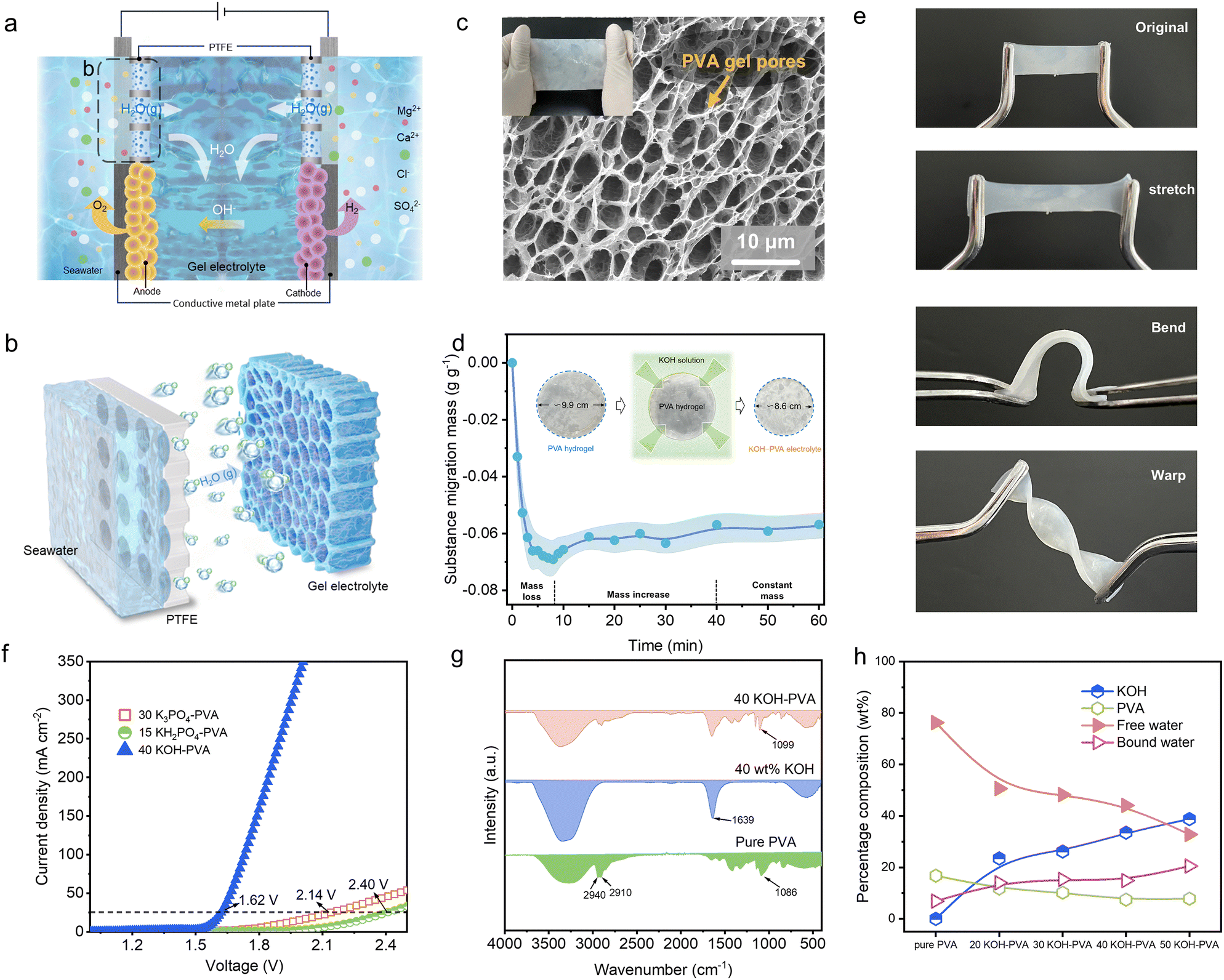 | ||
| Fig. 1 Formation of the gel electrolyte. (a) Gel-based direct seawater electrolysis system for hydrogen production. (b) Schematic of water from seawater absorbed by the gel electrolyte. (c) SEM image of the porous gel electrolyte. (d) Forming process of the gel electrolyte. (e) Flexible features of the gel electrolyte: adaptable to stretching, bending and warping. (f) Linear sweep voltammetry (LSV) curves of different gel electrolytes. (g) Fourier transform infrared spectroscopy (FTIR) of pure PVA, KOH solution, and 40 KOH–PVA gel electrolyte membranes. (h) Content curves of KOH, PVA, bound water and free water of KOH–PVA. | ||
Preparation of the gel electrolyte
The gel electrolyte is based on polyvinyl alcohol (PVA) as the polymer matrix. The preparation process involves initially freezing the PVA aqueous solution, followed by direct immersion into a liquid electrolyte with low vapour pressure, high ionic conductivity, a wide water decomposition window, and excellent electrochemical stability. A polymer network with three-dimensional micropores was constructed during the freezing process and was prepared for the subsequent electrolyte storage and functionalization. During the freezing process, the internal water condensed and aggregated into ice crystals and squeezed the PVA polymer chains closer to each other; this led to the formation of hydrogen bonds and dipole moments between the adjacent PVA molecular chains. The three-dimensional structure of the PVA network was solidified. Scanning electron microscopy (SEM) revealed abundant pores ranging from 2.8 to 5.8 μm in size in the gel electrolyte; these pores provided ample channels for ion and water molecular migration during the electrolysis process (Fig. 1c and Fig. S1, ESI†). When the frozen polymer matrix was immersed in a high-concentration electrolyte, the electrolyte rapidly infiltrated the interior of the PVA network. Water molecules within the pores and between PVA molecular chains were expelled due to the Hofmeister effect,23–25 leading to further densification of the gel. Owing to rapid dehydration, the mass of the gel electrolyte rapidly decreased and the volume decreased. As equilibrium was achieved between the amount of water inside and outside the gel, the rate of water loss slowed, and KOH continuously diffused into PVA, causing a slight increase in the mass of the gel electrolyte (Fig. 1d).Driven by hydrogen bonding and dipole moments,26–28 KOH interacts with the hydroxyl groups of PVA molecular chains and is absorbed and fixed within the porous framework of PVA. The prepared gel electrolyte can adapt to various deformations, such as stretching, bending and warping, and exhibited excellent flexibility (Fig. 1e and Fig. S2, ESI†). Various gel electrolytes can be used for seawater electrolysis and include those made of KOH–PVA, K3PO4–PVA and KH2PO4–PVA (gel electrolytes prepared from PVA immersed in KOH, K3PO4 and K2HPO4 solutions, respectively); they have overpotentials of 0.39 V, 0.905 V and 1.17 V, respectively, at a current density of 25 mA cm−2 (Fig. 1f). Compared with the ionic conductivity of 30 K3PO4–PVA (5.17 mS cm−1) and 15 KH2PO4–PVA (9.91 mS cm−1), the 40 KOH–PVA gel electrolyte exhibits superior ionic conductivity (259.51 mS cm−1) (Fig. S3 (ESI†), 30 K3PO4–PVA, 15 KH2PO4–PVA and 40 KOH–PVA are fabricated using frozen PVA immersed in 30 wt% K3PO4, 15 wt% KH2PO4 and 40 wt% KOH solutions, respectively). In addition, 40 KOH–PVA exhibits excellent water capture behaviour, with an average of approximately 0.55 g cm−2 h−1 over 10 minutes (Fig. S4, ESI†). Therefore, KOH–PVA demonstrated greater potential.
To further understand the interaction between KOH and PVA in the gel electrolyte, Fourier transform infrared (FTIR) spectroscopy was employed. FTIR analysis reveals a certain interaction and dependency between KOH and PVA (Fig. 1g and Fig. S5, ESI†). A new characteristic peak appears at 1639 cm−1, which likely occurs because KOH entered the gel.26 The peaks at 2940 cm−1 and 2910 cm−1 in the infrared spectrum of pure PVA correspond to the asymmetric and symmetric stretching vibrations of C–H in PVA, respectively.29 As the concentration of KOH increases (Fig. S5, ESI†), the intensity of the v(C–O) peak at 1086 cm−1 weakens and shifts to higher wavenumbers (1093, 1095, 1099, and 1101 cm−1 for 20 KOH–PVA, 30 KOH–PVA, 40 KOH–PVA, and 50 KOH–PVA, respectively). This shift is attributed to the strong electron-donating nature of the oxygen atoms in the –OH groups of PVA, and the K+ ions form C–O⋯K-type electrostatic interactions with the C–O bonds.26 Additionally, a broad peak corresponding to –OH stretching is observed between 3000 and 3500 cm−1 and shifts to higher wavenumbers with increasing KOH concentration. This shift is related to a reduction in the number and strength of the hydrogen bonds.30 The interaction between the K+ ions and the O atoms in PVA reduces the number of sites available for hydrogen bond formation by the O atoms of PVA. Unlike in pure PVA, a new network structure is formed in KOH–PVA; here, the hydrogen bonds and electrostatic interactions coexist.
To study the influence of the concentration of KOH solution on the gel electrolyte material, the compositions of the gel electrolytes prepared with KOH solutions at different concentrations were further analysed using thermogravimetric analysis (TGA) (Fig. 1h and Fig. S6, ESI†). With increasing KOH concentration, the number of KOH ions entering the gel electrolyte increases, and the high concentration of KOH solution causes a large amount of free water to escape from the polymer; thus, the proportion of free water decreases, and this process is the main reason for the observed reduction in the volume of the gel. To gain insight into the crystal phase structure of the gel electrolyte and its impact on ion migration, X-ray diffraction (XRD) analysis was conducted. Understanding the structural changes induced by the KOH incorporation is important for regulating the gel electrolyte performance (Fig. S7, ESI†). The width and intensity of the characteristic peaks (approximately 20° and 40.50°) become significantly broader and weaker, respectively, after the introduction of KOH into PVA. This facilitates the migration and movement of the ions in the polymer and enhances the ion conductivity.
Water migration and electrolysis
Owing to the vapour pressure difference between seawater and the gel electrolyte, water molecules generated by the natural evaporation of seawater migrate through the porous PTFE membrane to the surface of the gel electrolyte, where they are then absorbed by the gel electrolyte. A portion of the water molecules combine with KOH through solvation, whereas another portion forms hydrogen bonds with the hydroxyl groups on PVA (Fig. 2a). The water capture capability of the gel electrolyte was investigated. The KOH concentration plays a crucial role in regulating the water capture behaviour, as shown in Fig. 2b and Fig. S8 (ESI†). The average water migration rates within 10 min are approximately 0.16, 0.27, 0.55 and 0.71 g h−1 cm−2 in 20 KOH–PVA, 30 KOH–PVA, 40 KOH–PVA, and 50 KOH–PVA, respectively; these behaviours are suitable for electrolysis processes with maximum theoretical current densities of 475, 811, 1641 and 2122 mA cm−2. In addition, we found that increasing the thickness of the gel electrolyte can enhance the rate of water molecule migration over a period of time (Fig. S9, ESI†). This may be because a thicker gel electrolyte provides more space and binding sites to accommodate water molecules. And we found that the concentration of PVA has minimal influence on the water capture capacity (Fig. S10, ESI†). Within 10 min, the water migration rate of the three kinds of gel electrolytes prepared from the polymer matrix with different PVA concentrations is approximately 0.7 g h−1 cm−2 when the KOH concentration is about 50 wt%. We further explored the dimensional change caused by gel swelling after water migration. After ten minutes of water migration, the diameter of the 40 KOH–PVA gel electrolyte increased from 6.45 cm to 6.47 cm, reflecting a negligible deformation (Fig. S11, ESI†). In addition, because water is being consumed during electrolysis, the gel electrolyte does not continuously expand due to water absorption. | ||
| Fig. 2 Water migration and electrochemical properties. (a) Diagram illustrating the water capture principle for the KOH–PVA gel electrolyte. (b) Water capturing ability of KOH–PVA gel electrolytes prepared with different KOH concentrations and the corresponding current density achievable. (c) Various types of hydrogen bonding interactions occurring inside the 40 KOH–PVA gel electrolyte. (d) Raman spectra of the water content change on the other side of the gel electrolyte after water capture and migration for 10 min. (e) Changes in the ion conductivity of 40 KOH–PVA during the formation process. (f) Electrochemical impedance spectroscopy and ionic conductivity of the KOH–PVA gel electrolyte prepared with different KOH concentrations. (g) LSV curves for the hydrogen production using KOH–PVA gel electrolyte membranes prepared with different KOH concentrations. (h) The stress–strain curves of gel electrolytes prepared with KOH solutions of different concentrations. (i) Statistics of the maximum tensile stress and ionic conductivity of hydrogel electrolytes capable of transferring OH− ions. | ||
Molecular dynamic simulations were performed to reveal the water migration mechanism in the gel electrolyte (Fig. S12, ESI†). Water entering the gel electrolyte forms numerous hydrogen bonds with KOH, significantly outnumbering the water molecules bound to the hydroxyl groups on PVA (Fig. 2c). The hydrogen bonding between KOH and H2O dominates the water capture process of the gel electrolyte. The number of hydrogen bonds formed by H2O and KOH accounts for approximately 92.4%, whereas the number of hydrogen bonds formed by PVA–H2O accounts for only approximately 7.6% (Fig. S13, ESI†). The binding energy simulation results indicate that the binding energy between H2O and KOH ions is much lower than the binding energy between H2O and PVA; these results are in agreement with the above findings (Fig. S14, ESI†). Water molecules tend to bind with KOH ions and are transported to the electrode via continuous dissociation and association with the KOH ions inside the gel at different concentrations. Water molecule capture and internal migration processes were further investigated via Raman spectroscopy (Fig. 2d and Fig. S15, ESI†). Water molecules move longitudinally and axially in the gel electrolyte, and the O–H peak at 3100–3700 cm−1 in the Raman spectrum clearly increases in intensity after 10 min;31,32 this result indicates that water molecules can be transported and migrated within a certain spatial region.
Water molecules that entered the gel electrolyte and further migrated to the electrode surface decompose into hydrogen and oxygen due to the electric field. A strong correlation was observed between KOH and the electrochemical performance of gel electrolytes. Within 10 min, the KOH ions quickly enter the gel electrolyte, and the ionic conductivity of the gel electrolyte rapidly increased to approximately 234.4 mS cm−1, whereas the ionic conductivity stabilizes at approximately 278.9 mS cm−1 after 50 min (Fig. 2e). The ionic conductivities of the gel electrolytes treated with different KOH concentrations vary. After 24 h of immersion, the ion conductivities of 20 KOH–PVA, 30 KOH–PVA, 40 KOH–PVA and 50 KOH–PVA are 141.9, 185.0, 259.5 and 202.4 mS cm−1, respectively (Fig. 2f). Higher concentrations of KOH result in higher ion migration efficiency, but excessively high concentrations lead to incomplete ionization of KOH ions, impeding ion transport.
To reveal the influence of gel-electrolyte parameters such as the KOH concentration and gel thickness on the electrochemical performance of electrolysis, linear scan voltammetry (LSV) measurements were carried out. As shown in Fig. 2g, 40 KOH–PVA exhibits the best electrochemical performance, and its overpotential is approximately 0.67 V at 250 mA cm−2. In addition, the electrochemical performance is highly influenced by the thickness of the gel electrolyte. The overpotential of the gel electrolyte with a 0.64 mm thickness is approximately 0.62 V at 250 mA cm−2, whereas that of the gel electrolyte with a 3.87 mm thickness is approximately 0.83 V (Fig. S16, ESI†). This occurs mainly because a thinner gel electrolyte results in a shorter ion conduction distance, and the ion transport resistance is relatively weak; thus, the voltage loss in the ion transport process is lower, reducing the overpotential of the electrolytic hydrogen production process.
The stress–strain curves of gel electrolytes prepared with different ion regulation concentrations (Fig. 2h) were obtained. The maximum tensile stresses of 50 KOH–PVA, 40 KOH–PVA, 30 KOH–PVA and 20 KOH–PVA are 1.14, 0.88, 0.70 and 0.60 MPa, while their maximum strains are 896, 818, 728 and 674%, respectively. It is worth noting that the 40 KOH–PVA prepared in this study maintained a tensile stress and ion conductivity of 0.88 MPa and 259.5 mS cm−1, respectively, exhibiting outstanding performances compared with the recently reported flexible gel electrolytes (Fig. 2i).19–21,33–45
Direct seawater electrolysis with a gel electrolyte
A static cyclic test was carried out to verify the matching and stability of the two processes of electrolysis and self-dampening in the gel electrolyte (Fig. 3a). Each cycle consists of water migration for 50 minutes followed by electrolysis at a current density of 250 mA cm−2 (the catalytic area was 2 cm2) for 60 min. The gel electrolyte shows good stability for at least 6 cycles with no significant degradation in performance; this result indicates the potential for sustainable cycling and stable electrolysis. Therefore, when the amount of water migrating and the amount of electrolytic water consumed reach dynamic equilibrium, the system is able to provide a stable “in situ water capture-electrolysis” process, and seawater is directly used for continuous and efficient hydrogen production.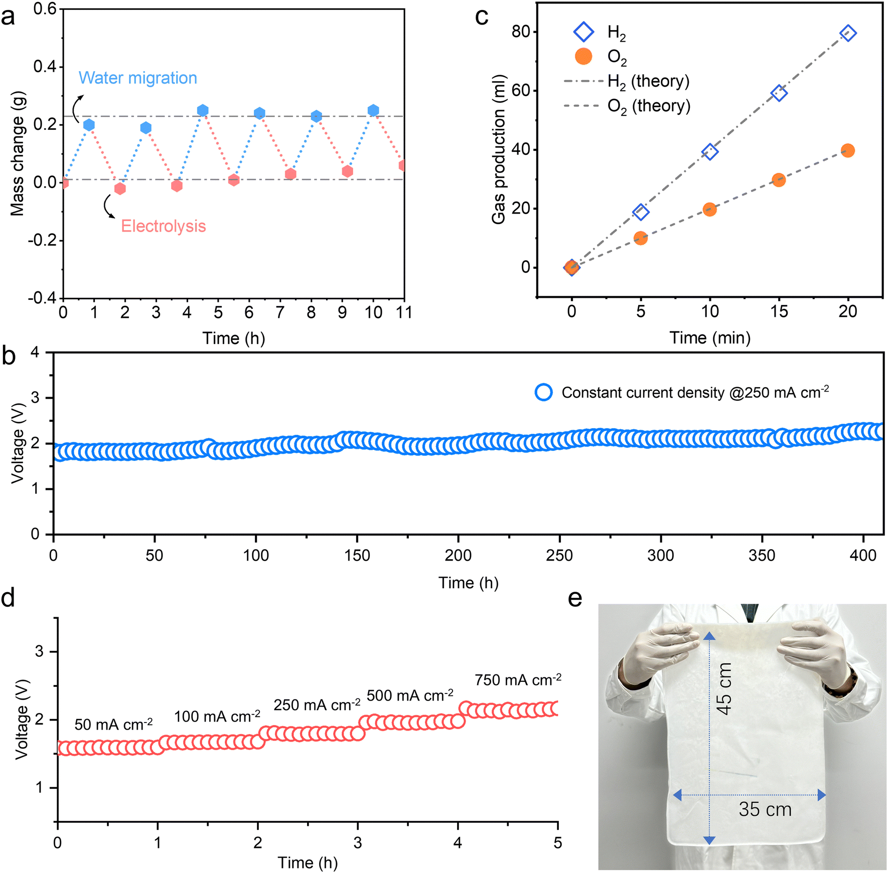 | ||
| Fig. 3 Stability and amplification potential. (a) Cyclic hygroscopic-electrolysis process of 40 KOH–PVA. (b) Hydrogen production stability test for direct seawater electrolysis using 40 KOH–PVA. (c) Gas production at the anode and cathode during direct seawater electrolysis using 40 KOH–PVA. (d) Stability test for direct seawater electrolysis using 40 KOH–PVA at different current densities. (e) Large-scale membrane preparation using 40 KOH–PVA. | ||
A gel electrolyte-based direct seawater electrolysis system was designed and proposed (Fig. S17, ESI†). At current densities of 250 mA cm−2 and 400 mA cm−2, the system using real seawater for electrolytic hydrogen production runs at voltages of approximately 1.8 V and 2.0 V, and the electrolytic energy consumption values are approximately 4.5 kW h Nm−3 H2 and 5 kW h Nm−3 H2, respectively (Fig. S18 and S19, ESI†). The system could run stably for more than 400 hours at 250 mA cm−2, exhibiting preferable stability (Fig. 3b). The hydrogen and oxygen produced from electrolysis were collected by drainage, and the Faradaic efficiency of hydrogen production was approximately 99% (Fig. 3c). Gas chromatography (GC) further demonstrated the barrier effect of the gel electrolyte. A continuous flow of H2 was introduced on one side, and the other side was purged with nitrogen. No H2 penetration is detected on the other side of the gel electrolyte after 60 h; this result indicates that the gel serves as a good barrier and can prevent hydrogen and oxygen from crossover (Fig. S20, ESI†). This occurs mainly because the PVA polymer had intrinsic barrier properties,46–48 and the remaining pores are further occupied by a KOH solution. This gel electrolyte with gas barrier properties replacing the tradition liquid electrolyte may help alleviate the crossover problem of hydrogen and oxygen in gas–liquid separators caused by liquid level tilt under fluctuating conditions (Fig. S21, ESI†).
The pores in the PTFE membrane remain clear, and the hydrophobicity of the PTFE membrane does not change; these results indicate that the PTFE membrane has a good chemical stability and tolerance in seawater and retains its ability to effectively prevent liquid water infiltration into the membrane pores of PTFE (Fig. S22 and S23, ESI†). The anode and cathode electrocatalysts retain their original morphology; thus, the complex ions in seawater did not penetrate the PTFE membrane and did not corrode the catalysts (Fig. S22, ESI†). ClO− concentration testing further quantitatively demonstrated the high efficiency of our system (Fig. S24, ESI†). No significant increase in the ClO− ion concentration was detected in the gel electrolyte, and the ion barrier rate of the system is above 99.99%. The FTIR spectra of the gel electrolyte before and after electrolysis indicate that the chemical structure of the gel electrolyte after electrolysis is stable (Fig. S25, ESI†). The peaks in the possible carbonate characteristic peak regions have been marked and analyzed.49–51 No obvious characteristic peaks belonging to HCO31− at 1305 and 1208 cm−1 were observed, nor were any obvious characteristic peaks belonging to CO32− at 1411 cm−1.52,53
The LSV curve indicates that the gel electrolyte can adapt to water electrolysis at a relatively high current density. No side reactions are observed for 40 KOH–PVA even at current densities up to 1000 mA cm−2 (Fig. S26, ESI†). A stepwise stability test was further carried out to verify the performance of the gel electrolyte at higher current densities ranging from 50 mA cm−2 to 750 mA cm−2 (Fig. 3d). And during continuous seawater electrolysis at a relatively high current density of 500 mA cm−2 for 70 hours, the voltage exhibits preferable stability, maintaining around 2.08 V throughout the process (Fig. S27, ESI†). In addition, these gel electrolytes can be easily scaled up. Through freezing and ion regulation processes, a single-sheet KOH–PVA membrane with a size of 35 × 45 cm2 was prepared and had a complete and uniform appearance (Fig. 3e). In the future, by stacking multiple groups of single devices, water migration and electrolysis parts can be spatially separated, thus enabling rapid and convenient scale-up and realizing a larger-scale hydrogen production under a certain volume (Fig. S28, ESI†).
Universality and diversity
A scenario was evaluated for matching renewable energy generation and storage for the electrolysis of unpurified water. A solar panel was employed to supply power for the electrolysis system. A battery and a constant current module were set up between the solar panels and the electrolysers to collect solar power and output a stable current for hydrogen production (Fig. 4a). The electrolysis experiment was conducted in a flowing and fluctuating river (Chengdu) at a constant current density of 250 mA cm−2, during which the scale of hydrogen production was approximately 1045 mL h−1. The hydrogen production process was monitored for two days under fluctuating solar power conditions. Despite the varying solar power input, the system maintained stable electrolysis for over 18 hours, and the water electrolysis voltage was approximately 1.95 V; this result demonstrates a good compatibility of the gel electrolyte-based seawater electrolysis system with renewable energy and stable hydrogen production characteristics (Fig. 4b). | ||
| Fig. 4 Application in various scenarios. (a) Hydrogen production system based on the 40 KOH–PVA gel electrolyte powered by a solar panel system, operating in flowing river. (b) Variation in the output power of the solar panels and the voltage stability of hydrogen production through electrolysis. (c) LSV curve of the gel electrolyte at 7.1 °C. (d) Gel electrolysis hydrogen production system that directly used moist gas passing through seawater as its water source. (e) Stability of the hydrogen production via gel electrolysis at different current densities and in different wet gas atmospheres. | ||
We further verified the feasibility of the gel electrolyte application in electrolysis at a low temperature. The LSV curve of the 40 KOH–PVA gel electrolyte was obtained at 7.1 °C (Fig. 4c). The results show that the overpotential of the system at 250 mA cm−2 is approximately 0.77 V; this value increases by approximately 0.1 V compared with the overpotential at 25 °C. This result shows the feasibility of seawater electrolysis in different cold regions.
The application of the gel electrolyte can be further expanded to directly capture water present in humid gas for electrolysis, as shown in Fig. 4d. Hydrogen was produced by sparging seawater with nitrogen to carry water vapour to the gel electrolyte as the water source for electrolysis at 60 °C and 25 °C. At 60 °C, the system operated stably for more than 20 h at voltages of 1.8 V and 2.2 V and current densities of 250 mA cm−2 and 500 mA cm−2, respectively. Even at 25 °C, 220 h of stability was attained at 100 mA cm−2 and a voltage of 1.9 V, indicating the universality and diversity of our system (Fig. 4e).
Conclusions
In summary, a porous-network-structured multifunctional gel electrolyte with self-dampening capability, electrochemical stability, and high ion conductivity was designed and developed through freezing and ion regulation. This gel electrolyte was innovatively applied in direct seawater electrolysis based on the water phase-transition mechanism. The water capture and transportation mechanism of the gel electrolyte were revealed, and the dominant role of KOH in the water migration and electrolysis processes was shown. This safe, compact and ingenious system provides a new approach for seawater electrolysis. Our system operated stably for more than 400 hours at a current density of 250 mA cm−2, with a Faradaic efficiency of 99%. A large-scale electrolyser based on gel electrolytes was further operated in a flowing river using renewable solar energy as the energy input, and can be used as a reference for the future expansion and integration of gel electrolyte systems with renewable energy sources. Furthermore, we demonstrated the potential of gel electrolytes to operate at a lower temperature (7.1 °C) and expanded their applicability by enabling hydrogen production directly from a humidified gas atmosphere in a complex environment. Our study lays the foundation for development of safe, lightweight and compact seawater electrolysis systems for application in far and deep oceans.Experimental
Materials
The materials used in this study included KOH (Adamas, >90%), NaCl (Greagent, 99.5%), PVA (1799), porous PTFE membranes, a commercial porous MoNi/NF catalyst (pore size 85 ppi, area density 450 g m−2; Kunshan Guangjiayan Electronic Materials), and a commercially available PtNi network catalyst (base network braided with 0.15 mm diameter nickel wire; Luzhou Hongjiang electrolysis equipment).Preparation of the PVA gel electrolyte
PVA precursor: PVA1799 particles were dissolved in deionized water, vigorously stirred and heated (90 °C) for 24 hours to obtain clear and transparent 10 wt%, 15 wt%, and 20 wt% PVA solutions. The PVA solutions were introduced into a polytetrafluoroethylene mould, and the PVA solutions were frozen at −20 °C for 24 hours to obtain 10 wt%, 15 wt%, and 20 wt% PVA precursors.In this study, gel electrolytes fabricated using frozen PVA (10 wt%) were immersed in 10 wt%, 20 wt%, 30 wt%, 40 wt% and 50 wt% KOH solutions for 24 hours; these electrolytes were referred to as 20 KOH–PVA, 30 KOH–PVA, 40 KOH–PVA and 50 KOH–PVA, respectively. The 10 wt%, 15 wt%, and 20 wt% PVA samples immersed in 50 wt% KOH solution were referred to as 50 KOH–10 PVA, 50 KOH–15 PVA, and 50 KOH–20 PVA, respectively. The gel electrolyte membranes prepared with 30 wt% K3PO4 solution and 15 wt% KH2PO4 solution containing 10 wt% PVA were referred to as 30 K3PO4–PVA and 15 KH2PO4–PVA, respectively.
Material characterization
Test for the hypochlorite ion content in gel electrolyte. The ion content in the gel electrolyte was determined by adding 1 g of gel electrolyte to 100 g of deionized water and stirring for 5 h to obtain a gel ion leaching solution. The concentration of hypochlorite (ClO−) in the leached solution was determined via the o-toluidine method.54
Water migration test
A 0.5 M NaCl solution was used as the simulated seawater. KOH–PVA gel and simulated seawater were placed on either side of a PTFE membrane, and the weight change in the gel was recorded at regular intervals. Here, we evaluated KOH–PVA gels prepared with different concentrations of PVA (10 wt%, 15 wt%, and 20 wt%) and different KOH concentrations (20 wt%, 30 wt%, 40 wt%, and 50 wt%) for water migration.Ion conductivity test
The ionic conductivity of the gel electrolyte was determined by using stainless steel conductive plates that held a 2 × 2 cm2 piece of gel electrolyte. An AC impedance (EIS) test was performed in the range of 0.1–106 Hz on a Solartron electrochemical workstation. The ionic conductivity of the gel electrolyte was calculated using the formula σ = l(RbA)−1, where A is the gel area; since the area parameter was entered before the impedance test, RbA is the transverse intercept of the impedance spectrum curve, and l is the gel electrolyte thickness.Linear sweep voltammetry
LSV tests in the low-current density range of the gel and catalyst systems were performed using an electrochemical workstation (CHI660, CH Instruments) at a scanning speed of 2 mV s−1. LSV tests at higher current densities were carried out with a power supply (ITECH, IT6900A) at a scanning speed of 2 mV s−1. The cathode and anode catalysts are a PtNi mesh and MoNi/NF, respectively.Stability test for electrolysis
The electrolytic voltage stability of a single cell was recorded using a multimeter with a power supply (ITECH, IT6900A) at different constant current densities. The electrolytic voltage stability of hydrogen production from five electrolytic cells using solar panels as a power source was examined at 250 mA cm−2 (2.5 A) using a multimeter, which recorded the voltage change over an effective area of 10 cm2. The cathode and anode catalysts were PtNi mesh and MoNi/NF, respectively.Calculation of energy consumption for hydrogen production
The actual energy consumption Q for electrolytic hydrogen production is calculated as follows:where I is the current and U is the voltage. The resulting H2 volume V is subsequently calculated as follows:

| V = 22.4 × I × t/(Z × F). |
![[thin space (1/6-em)]](https://www.rsc.org/images/entities/char_2009.gif) 485 C mol−1. Thus, the energy consumption is as follows: Q = W/V.
485 C mol−1. Thus, the energy consumption is as follows: Q = W/V.
Ion barrier rate calculation
| Ion barrier rate = (c1 − c2)/c1 × 100%, |
Assembly of a single laboratory-scale gel electrolyser
The laboratory-scale gel electrolytic cell had a symmetrical structure with a 40 KOH–PVA electrolyte membrane with a size of 6 × 7.5 cm2 (thickness of approximately 1.5 mm) in the middle, followed by a catalyst layer, a conductive metal plate, a porous PTFE film and an electrolytic cell frame. The anode and cathode catalyst layers contained commercial porous MoNi/NF and PtNi meshes, respectively. The anode and cathode of the tank had a 3 mm diameter hole for discharging gases. There were 6 × 4 cm2 openings on the outer frame of the electrolyser, and these openings were used to place the porous PTFE film to isolate the liquid seawater from the outside while providing water migration channels. Before starting operation, inert gas such as nitrogen is introduced to remove impurities in the electrolyser.Assembly of the electrolytic hydrogen production system based on renewable energy
The electrolytic hydrogen production system based on renewable energy consisted of solar panels, a current and voltage stability control module, a storage battery and a hydrogen production device. The rated output voltage of the solar panel was 18 V, the capacity of the battery was 20 AH, and the water electrolysis hydrogen production device was composed of five laboratory-scale gel electrolysers in parallel. The current and voltage stability control module could transfer the unstable electrical energy from the solar panel to the battery and supply energy to the electrolytic cell. When the power supply from the solar panel was insufficient, the electrical energy stored in the battery could be supplied to the electrolytic cell.Molecular dynamics simulations
Molecular dynamics simulations were performed to explore the structure and dynamics of H2O molecules in the PVA–KOH gel. Three PVA chains (the first two were made of 200 linked repeat units, and the third one was formed with 100 units), 7290 H2O molecules, and 1365 KOH molecules were placed in a periodic unit cell (7.26 nm on each side) to form a PVA–KOH gel model (Fig. S12a, ESI†). The PVA–KOH gel model was subjected to geometry minimization to remove the steric clashes, followed by a 300 ps NPT run at 300 K and 1 atm to reach a reasonable density. Finally, a further 10000 ps NVT run at 300 K was performed. The final results were analysed on the basis of the last 3000 ps simulation period (Fig. S12b, ESI†).
Stability test of seawater electrolysis in a wet gas atmosphere
Dry N2 was injected into the seawater at a rate of 2 mL s−1. The N2 carried water molecules present in the seawater to the gel electrolyte, and the water vapour was absorbed by the gel electrolyte for hydrogen production. The stability of hydrogen production via electrolysis was examined at different seawater temperatures and current densities. The cathode and anode catalysts were PtNi mesh and MoNi/NF, respectively.Author contributions
H. X., T. L., Z. Z. and W. T. conceived and designed the project. W. T., Z. Z., D. Y., Y. L., L. Z., Y. W., C. L., W. J. and Y. F. W. performed characterization and experiments. H. X., T. L. and Z. Z managed and supervised the project. W. T., Z. Z., T. L. and H. X. wrote the manuscript. All authors reviewed the manuscript.Data availability
All the data supporting the findings of this study are presented in the paper and its ESI.† This study did not generate or analyze datasets or code.Conflicts of interest
There are no conflicts to declare.Acknowledgements
We would like to thank the National Natural Science Foundation of China (Grant No. 51827901, 52470125, 52403383, 52104400, 52304427, and 52374133). This work is supported by the Sustainable Development Technology Special Project of Shenzhen Science and Technology Innovation Commission (KCXST20221021111601003). This work is also supported by the National Key R&D Program of China (grant no. 2022YFB4102101). This work is also supported by the Postdoctoral Innovation Talent Support Program (No. BX20240240). We are grateful for the support from the Program for Guangdong Introducing Innovative and Entrepreneurial Teams (Grant No. 2019ZT08G315). We would like to thank the Sichuan Natural Science Foundation (Grant No. 2024NSFSC1157 and 2024NSFSC1139) and Sichuan Province Science and Technology Innovation Seed Project (MZGC20240032). We thank the Sichuan University Interdisciplinary Innovation Fund. We thank the Institute of New Energy and Low-Carbon Technology (Sichuan University).Notes and references
- Y. Xia, H. Cheng, H. He and W. Wei, Commun. Eng., 2023, 2, 22 CrossRef CAS.
- G. Glenk and S. Reichelstein, Nat. Energy, 2019, 4, 216–222 CrossRef CAS.
- M. El-Shafie, Results Eng., 2023, 20, 101426 CrossRef CAS.
- S. Shiva Kumar and H. Lim, Energy Rep., 2022, 8, 13793–13813 CrossRef.
- B. Amini Horri and H. Ozcan, Curr. Opin. Green Sustainable Chem., 2024, 47, 100932 CrossRef CAS.
- D. Tonelli, L. Rosa, P. Gabrielli, K. Caldeira, A. Parente and F. Contino, Nat. Commun., 2023, 14, 5532 CrossRef CAS.
- J. Guo, Y. Zheng, Z. Hu, C. Zheng and J. Mao, et al. , Nat. Energy, 2023, 8, 264–272 CrossRef CAS.
- F. Gao, P. Yu and M. Gao, Curr. Opin. Chem. Eng., 2022, 36, 100827 CrossRef.
- F. Dionigi, T. Reier, Z. Pawolek, M. Gliech and P. Strasser, ChemSusChem, 2016, 9, 962–972 CrossRef CAS PubMed.
- S. Dresp, T. Ngo Thanh, M. Klingenhof, S. Brückner, P. Hauke and P. Strasser, Energy Environ. Sci., 2020, 13, 1725–1729 RSC.
- L. Shi, R. Rossi, M. Son, D. M. Hall and M. A. Hickner, et al. , Energy Environ. Sci., 2020, 13, 3138–3148 RSC.
- H. Xie, Z. Zhao, T. Liu, Y. Wu and C. Lan, et al. , Nature, 2022, 612, 673–678 CrossRef CAS PubMed.
- T. Liu, Z. Zhao, W. Tang, Y. Chen and C. Lan, et al. , Nat. Commun., 2024, 15, 5305 CrossRef CAS PubMed.
- N. Y. Sergiienko, L. S. P. Da Silva, E. E. Bachynski-Polić, B. S. Cazzolato, M. Arjomandi and B. Ding, Renewable Sustainable Energy Rev., 2022, 162, 112477 CrossRef.
- O. S. Ibrahim, A. Singlitico, R. Proskovics, S. McDonagh, C. Desmond and J. D. Murphy, Renewable Sustainable Energy Rev., 2022, 160, 112310 CrossRef CAS.
- A. H. El-Kady, M. T. Amin, F. Khan and M. M. El-Halwagi, Int. J. Hydrogen Energy, 2024, 52, 1312–1332 CrossRef CAS.
- H. Tüysüz, Acc. Chem. Res., 2024, 57, 558–567 Search PubMed.
- S. Hu, B. Guo, S. Ding, F. Yang and J. Dang, et al. , Appl. Energy, 2022, 327, 120099 CrossRef CAS.
- S. Sun, X. Zhao, C. Gao, L. Xiao and R. Sun, Chem. Eng. J., 2024, 495, 153781 CrossRef CAS.
- D. Wang, Z. Li, L. Yang, J. Zhang, Y. Wei, Q. Feng and Q. Wei, Chem. Eng. J., 2023, 454, 140090 CrossRef CAS.
- G. Ling, J. Ren, Z. Wang, R. Ren and Y. Lv, J. Energy Storage, 2024, 100, 113549 CrossRef.
- O. S. Jeon, E. S. Ko, Y. Y. Park, D. Hong, S. H. Lee, Y. P. Jeon, Y. La, S. Kim, I. Lee, G. Park, E. J. Lee, S. Kang, Y. J. Yoo and S. Y. Park, Adv. Energy Mater., 2023, 13, 2300285 CrossRef CAS.
- Y. Zhang and P. S. Cremer, Curr. Opin. Chem. Biol., 2006, 10, 658–663 CrossRef CAS.
- X. Sun, Y. Mao, Z. Yu, P. Yang and F. Jiang, Adv. Mater., 2024, 36, 2400084 CrossRef CAS.
- W. Cui, Y. Zheng, R. Zhu, Q. Mu, X. Wang, Z. Wang, S. Liu, M. Li and R. Ran, Adv. Funct. Mater., 2022, 32, 2204823 CrossRef CAS.
- F. Santos, J. P. Tafur, J. Abad and A. J. Fernández Romero, J. Electroanal. Chem., 2019, 850, 113380 CrossRef CAS.
- H. Najafi Fath Dehghan, A. Abdolmaleki, M. Pourahmadi, P. Khalili, A. R. Arvaneh and M. Sadat-Shojai, J. Mol. Liq., 2023, 382, 121860 CrossRef CAS.
- M. Miotke-Wasilczyk, J. Kwela, A. Lewkowicz and M. Józefowicz, Spectrochim. Acta, Part A, 2023, 284, 121802 CrossRef CAS PubMed.
- J. Qiao, J. Fu, R. Lin, J. Ma and J. Liu, Polymer, 2010, 51, 4850–4859 CrossRef CAS.
- M. Reichenbächer and J. Popp, Challenges in Molecular Structure Determination, 2012 Search PubMed.
- F. Li, Z. Li, Y. Wang, S. Wang, X. Wang, C. Sun and Z. Men, Spectrochim. Acta, Part A, 2018, 196, 317–322 CrossRef CAS.
- F. Ni, N. Qiu, P. Xiao, C. Zhang, Y. Jian, Y. Liang, W. Xie, L. Yan and T. Chen, Angew. Chem., Int. Ed., 2020, 59, 19237–19246 CrossRef CAS.
- C. Zou, L. Chen, Q. Liu, W. Lu, X. Sun, J. Liu, Y. Lei, W. Zhao and Y. Liu, Langmuir, 2024, 40, 9999–10007 CrossRef CAS.
- N. Chen, L. Tao, X. Lu, M. M. Hassan, R. Yang, J. Liu and Q. Lu, Giant, 2024, 17, 100230 CrossRef CAS.
- K. Jin, J. Sun, C. Li, X. Su, A. Chen, Q. Han, Z. Zhang, Y. Fu, Y. Zhao and Z. Cai, J. Power Sources, 2024, 616, 235139 CrossRef CAS.
- Q. Zhang, L. Zhao, H. Yang, L. Kong and F. Ran, J. Membr. Sci., 2021, 629, 119083 CrossRef CAS.
- Y. Zhang, Y. Chen, M. Alfred, F. Huang, S. Liao, D. Chen, D. Li and Q. Wei, Composites, Part B, 2021, 224, 109228 CrossRef CAS.
- X. Fan, J. Liu, Z. Song, X. Han, Y. Deng, C. Zhong and W. Hu, Nano Energy, 2019, 56, 454–462 CrossRef CAS.
- Z. Song, J. Ding, B. Liu, X. Liu, X. Han, Y. Deng, W. Hu and C. Zhong, Adv. Mater., 2020, 32, 1908127 CrossRef CAS.
- L. Ma, S. Chen, D. Wang, Q. Yang, F. Mo, G. Liang, N. Li, H. Zhang, J. A. Zapien and C. Zhi, Adv. Energy Mater., 2019, 9, 1803046 CrossRef.
- N. Sun, F. Lu, Y. Yu, L. Su, X. Gao and L. Zheng, ACS Appl. Mater. Interfaces, 2020, 12, 11778–11788 CrossRef CAS.
- Y. Zhang, C. Li, X. Cai, J. Yao, M. Li, X. Zhang and Q. Liu, Electrochim. Acta, 2016, 220, 635–642 CrossRef CAS.
- X. You, C. Qiao, D. Peng, W. Liu, C. Li, H. Zhao, H. Qi, X. Cai, Y. Shao and X. Shi, Polymers, 2021, 13, 9 CrossRef CAS.
- D. Jiang, H. Wang, S. Wu, X. Sun and J. Li, Small Methods, 2022, 6, 2101043 CrossRef CAS.
- N. Zhao, F. Wu, Y. Xing, W. Qu, N. Chen, Y. Shang, M. Yan, Y. Li, L. Li and R. Chen, ACS Appl. Mater. Interfaces, 2019, 11, 15537–15542 CrossRef CAS.
- H. A. Silvério, W. P. Flauzino Neto and D. Pasquini, J. Nanomater., 2013, 2013, 289641 CrossRef.
- X. Yun and T. Dong, Food Packaging, Academic Press, 2017, pp. 147–184 Search PubMed.
- Z. Yu, B. Li, J. Chu and P. Zhang, Carbohydr. Polym., 2018, 184, 214–220 CrossRef CAS.
- S. R. Allayarov, M. P. Confer, D. A. Dixon, T. N. Rudneva, L. A. Kalinin, E. M. Tolstopyatov, I. A. Frolov, L. F. Ivanov, P. N. Grakovich and O. N. Golodkov, Polym. Degrad. Stab., 2020, 181, 109331 CrossRef CAS.
- F. Santos, J. P. Tafur, J. Abad and A. J. Fernández Romero, J. Electroanal. Chem., 2019, 850, 113380 CrossRef CAS.
- I. M. Jipa, A. Stoica, M. Stroescu, L. Dobre, T. Dobre, S. Jinga and C. Tardei, Chem. Pap., 2012, 66, 138–143 CAS.
- X. Li, L. Li, G. Chen, X. Chu, X. Liu, C. Naisa, D. Pohl, M. Löffler and X. Feng, Nat. Commun., 2023, 14, 4034 CrossRef CAS PubMed.
- A. A. I. Velez, E. Reyes, A. Diaz-Barrios, F. Santos, A. J. Fernández Romero and J. P. Tafur, Gels, 2021, 7, 256 CrossRef CAS PubMed.
- F. Sun, J. Qin, Z. Wang, M. Yu and X. Wu, et al. , Nat. Commun., 2021, 12, 4182 CrossRef CAS PubMed.
Footnote |
| † Electronic supplementary information (ESI) available. See DOI: https://doi.org/10.1039/d5ee00453e |
| This journal is © The Royal Society of Chemistry 2025 |