
Covalent organic framework membranes for energy storage and conversion
Liyu
Zhu
a,
Yu
Cao
b,
Ting
Xu
 *a,
Hongbin
Yang
a,
Luying
Wang
c,
Lin
Dai
a,
Fusheng
Pan
*b,
Chaoji
Chen
*d and
Chuanling
Si
*a
*a,
Hongbin
Yang
a,
Luying
Wang
c,
Lin
Dai
a,
Fusheng
Pan
*b,
Chaoji
Chen
*d and
Chuanling
Si
*a
aState Key Laboratory of Bio-based Fiber Materials, Tianjin Key Laboratory of Pulp and Paper, Tianjin University of Science and Technology, Tianjin 300457, P. R. China. E-mail: xuting@tust.edu.cn; sichli@tust.edu.cn
bKey Laboratory for Green Chemical Technology of Ministry of Education, School of Chemical Engineering and Technology, Tianjin University, Tianjin 300072, P. R. China. E-mail: fspan@tju.edu.cn
cBeijing Key Laboratory of Lignocellulosic Chemistry, Beijing Forestry University, Beijing 100083, P. R. China
dSchool of Resource and Environmental Sciences, Hubei Biomass-Resource Chemistry and Environmental Biotechnology Key Laboratory, Wuhan University, Wuhan 430079, P. R. China. E-mail: chenchaojili@whu.edu.cn
First published on 19th March 2025
Abstract
Covalent organic frameworks (COFs) are a class of porous crystalline materials based on reticular and dynamic covalent chemistry. Flexible molecular design strategies, tunable porosity, modifiable frameworks, and atomically precise structures have made them powerful platforms for developing advanced devices in energy storage and conversion. In particular, the emergence of COF membranes has dramatically expanded the application scenarios for insoluble and un-processable COF powders and opened new doors for their utilization in the field of energy storage and conversion. In this process, exciting research activities have emerged, ranging from synthesis methods to energy-related applications of COF membranes. Therefore, in this critical review, current research progress on the utilization of COF membranes for energy devices, specifically fuel cells, rechargeable batteries, supercapacitors, and photo/osmotic energy conversion, is first comprehensively reviewed in terms of the core features, design principles, synthesis methods, properties, engineering technologies and applications of COF membranes. Meanwhile, the key challenges and prospects of COF membranes in energy-related applications are also meticulously reviewed and addressed. We sincerely expect that this review can further stimulate the research enthusiasm for COF membranes in energy-related applications and offer valuable guidance for the design and application strategies of advanced COF membranes with a focus on energy devices.
Broader contextMembranes are pivotal in a myriad of energy production processes and modern separation techniques. For membranes in energy-related applications, key properties of such materials include appropriately sized pores, finely tuned interactions between desired permeants and the membrane, sufficient chemical stability/mechanical strength, etc. Compared to the multi-scale heterogeneity and dynamics of conventional polymer membranes, the rigid framework, well-defined molecular structure, and directionally editable nature of covalent organic frameworks (COFs) bring great possibilities for precisely resolving the transport behavior of ions. Notably, most of the conventional COF synthetic approaches offer poor control over the material's morphology and thus result in insoluble and unprocessable microcrystalline powders. Therefore, fabricating these insoluble particles for further application presents a formidable challenge. In this case, the emergence of COF membranes brings new possibilities for iterating and upgrading energy storage and conversion devices. This review comprehensively analyses and focuses on the key features of COF membranes for energy-related applications from representative application examples, including ionic transport, charge transport, selectivity, mechanical property, crystallinity, stability, and interface connectivity. This review will provide inspiration for the development of better COF membranes for energy storage and conversion and boost the enduring enthusiasm in this field. |
1. Introduction
The increasing environmental pollution and global energy consumption stemming from fossil-fuel usage have spurred worldwide efforts toward developing renewable, sustainable, and environmentally friendly energy solutions. Energy storage and conversion are the most efficient and advanced energy utilization technologies for converting sustainable energy into transportable and stable chemical energy and have grown by leaps and bounds in recent decades.1–3 Among them, a variety of advanced energy systems have proliferated, such as fuel cells, rechargeable batteries, flow batteries, supercapacitors, and photo/osmotic energy conversion devices. A major route to advancing these energy-related devices is the discovery of critical electrodes, electrolytes, or separator materials with higher performance.4,5 Indeed, the performance of energy storage and conversion devices depends primarily on two fundamental microscopic processes: charge and mass (ion) transport. That is, it is essential to employ materials with suitable charge or mass transfer capabilities in various functional components.In all of these well-established and emerging energy-related systems, membrane-based components generally serve to transport ions/electrons and isolate electrochemical reactions.6,7 For example, the designable mass transfer selectivity/directionality of membrane-based electrolyte/separator and the achievable interfacial connectivity/flexibility of membrane-based electrode are the most representative and advanced sources.8–15 To achieve exceptional conversion efficiencies and broader application scenarios, membranes typically need to possess high ionic conductivity, excellent selectivity, superior durability, high safety, and low fabrication cost.16 Generally, the commonly explored/employed separation or exchange membranes in energy storage/conversion devices are polymeric materials, and it is worth noting that the molecular structure of conventional organic polymers is typically amorphous, which makes it challenging to gain explicit control over their pore environment and molecular structure, leading to insufficient insight into structure–property relationships and ionic conduction mechanism.17–19 Especially for improving the performance of these electrochemical devices, separation membranes with precisely tunable and customizable pore structures are particularly fascinating.
As an emerging porous crystalline material, covalent organic frameworks (COFs) are assembled by covalent bonding of organic structural units with precise symmetry, which have the advantage of well-defined structures, high porosity, and adjustable nanopores.20 More encouragingly, the construction of COF topologies depends on the geometry of the individual building blocks and the nature of the covalent connections between them, which endows COFs with tremendous possibilities in structural design.21 Concomitantly, COFs also offer the possibility of modifying active fragments on their frameworks or impregnating active molecules in their nanochannels.22–24 With the assistance of these characteristics, COFs have been extensively researched in energy storage and conversion over the past decade (Fig. 1a).25–28 In 2015, for the first time, the formation of spiroborate-linked COFs via polyol condensation with trimethyl borate attracted tremendous attention due to their superior Li+ conductivity after treatment with Li+ solution, and this triggered a spurt in the development of ionic COF materials.29 Subsequent studies reported that various anionic COFs (e.g., silicate, sulfonate, and imidazolate) and cationic COFs (e.g., imidazolium, ethidium, ammonium, guanidinium, and dimidium) with diverse linkage types were employed to facilitate efficient and selective ion transport (Fig. 1b). However, it is noteworthy that the synthesized COF crystallites are typically integrated at different length scales by uncontrolled covalent self-assembly, which leads to the precipitation of polycrystalline powders. In this context, COF materials present in the form of bulk polycrystalline powders usually cannot meet the specific requirements of applications related to energy storage devices and mass transfer materials.30–32 Therefore, this provided the much-needed impetus and opened the floodgates of research on COF membranes.
 | ||
| Fig. 1 General overview of COF membrane applications in energy storage and conversion. (a) Schematic of the preparation method, key requirements, and energy-related applications of COF membranes; (b) timeline of the development of representative ion-conducting COFs; (c) number of publications using “COF membranes” as topic keywords and research activities relating to COF membranes according to the Web of Science. | ||
As we mentioned above, the orderly assembly of organic linkers through covalent bonds results in COFs with uniform pore sizes, high pore density, and regular topology. Indeed, these properties are uncontrollably attractive for the construction of advanced separation membrane materials.33–35 Briefly, the length, shape, and symmetry of the linker determine the geometry of the framework of COFs, which allows the COF membranes to be fine-tuned over a wide range of precisely defined pore sizes to accommodate/anchor guest molecules or ions with different van der Waals volumes. In addition, the functionality of COF membrane can be precisely tuned in a targeted manner by introducing different functional groups on linkers, resulting in a precise control of host–guest interaction in an attractive or repulsive manner. In terms of preparation methods for COF membranes, a variety of strategies have been developed for the direct or indirect synthesis of self-supported and freestanding COF membranes, including in situ growth, interfacial polymerization, layer-by-layer stacking, blending, etc. It can be said that the updating and iteration of these preparation strategies have also further advanced the development of COF membranes. Concurrently, the exponential growth in the number of publications on COF membranes also indicates the considerable interest of the scientific community in this field (Fig. 1c).
Although research on the application of COF membranes in energy-related devices may be in its infancy, the characteristics discussed above have a clear contribution to the charge and mass transport required in energy storage and conversion processes, and have a profound impact on the development of the new-energy sector. In this review, we focus on the key features (e.g., pore size, surface charge, hydrophilicity, crystallinity, ion transport, electron transport, selectivity, crystallinity, mechanical property, interface connectivity, and stability) and design principles of COF membranes for energy storage and conversion applications, established interconnections between different membrane-formation methods and specific applications, and evaluated their performance in terms of structural design. Meanwhile, the development of COF membranes in fuel cells, rechargeable batteries, flow batteries, supercapacitors, solar energy conversion, and osmotic energy conversion applications are highlighted. The prospects and challenges in the development of COF membranes for electrochemical applications are comprehensively discussed. It is sincerely expected that this review will contribute some inspiration for future research in energy storage and conversion applications based on COF membranes.
2. Opportunities for COF membranes in energy storage and conversion
Research into various advanced energy storage and conversion devices is increasing dramatically to meet the demands of sustainable development and decarbonization.36–41 Based on the discussion of the principles of energy device design and the challenges of constructing such devices using conventional materials, the most crucial requirement for the development of an efficient electrochemical device is the configuration of membranes capable of fast and durable transport of ions between electrodes.5,42,43 Generally, these membranes can be categorized as follows: (i) membrane assembled from flexible chain segments of polymers; (ii) membrane assembled from polymer and organic/inorganic nanomaterials; (iii) membrane assembled from rigid building blocks. Indeed, the flexible ion channels constructed from polymer chain segments (such as some polymer-based membranes and biomass-based membranes) may collapse at low humidity, leading to a decrease in ion conduction efficiency.44–48 For some two-dimensional membranes (such as GO membrane, MXene membrane, and MOF membrane), although their rigidly ordered ion channels are less susceptible to environmental influences, their relatively low ionic conduction rate, stability, and more complicated modifications limit their applications to some extent.49,50 In comparison, COFs have more flexible modification methods and structures relying on unique linkage rules. In terms of the ionic conduction mechanism (Grotthuss mechanism and vehicular mechanism), ions such as H+, Li+, Na+, and OH− can be transferred between adjacent conduction sites with opposite charges. For COFs, ion-conducting COFs are typically achieved by decorating the COF backbone with ion donor groups (e.g., sulfonic acid, carboxylic acid, and quaternary ammonium) or loading proton carriers (e.g., H3PO4, phytic acid, ionic liquid, imidazole) into their nanopores.51–53 In this regard, decorating the framework of COFs with ion-conducting groups is usually recognized as the Grotthuss conduction mechanism, whereas filling their pores with proton carriers is usually recognized as a vehicular conduction mechanism. With these two versatile preparation strategies, COFs become an ideal and advanced platform to facilitate rapid ion transport. Moreover, the reaction process of COFs is generally governed by thermodynamics, which controls the reversibility of bond formation.54 This reversible chemical reaction allows for a self-correcting process, thus generating highly periodic networks that can further develop into crystalline structures. In this process, COFs with defined pore sizes, spatial structure, and charge properties can be designed topologically through the periodic connection and arrangement of preformed building blocks. Moreover, in addition to pore size regulation, pore wall modification and guest molecule incorporation are also sources of advancement of COFs for energy-related applications (Fig. 2a).55,56 | ||
| Fig. 2 Advances in COFs and COF membranes for energy storage and conversion applications. (a) Schematic illustration of the advantages of COFs in energy-related applications; (b) schematic illustration of functional COFs prepared by post-synthetic modification strategy for electrochemical devices; (c) schematic illustration of functional COFs prepared by functional groups modification strategy for electrochemical devices; (d) schematic illustration of functional COFs prepared by ionic precursors strategy for electrochemical devices; (e) schematic illustration of the advantages of COF membranes in energy-related applications. | ||
Depending on the expected application in electrochemical energy storage and conversion, the chemical structure of COFs can be flexibly controlled by exploiting different methods to manipulate the number and properties of functional groups and active sites. In general, functional monomers can be directly used in the synthesis of COFs, in addition to which backbone modification is another route to customize the chemical structure and function of COFs. The conversion from framework to framework can be achieved through chemical reactions of the linker or exchange of the entire structural unit (Fig. 2b).57–59 Moreover, some functional groups are difficult to incorporate into COFs by typical solvothermal or mechanochemical synthesis methods due to their incompatibility with the structural units of COFs or reaction conditions. In this regard, introducing functional molecules into the COF frameworks through chemical transformation and maintaining their topologies can effectively tune the functional properties of COFs (Fig. 2c).60,61 That is, the functional groups or molecules that cannot be synthesized directly can be introduced into the framework of COFs by applying functional group modifications. Furthermore, the functional groups on the linkers of COFs can be used to coordinate and bind ionic precursors introduced into the pore system. By applying this strategy, some ions or molecules can be effectively immobilized on the frameworks of COFs (Fig. 2d).62,63
In addition, membranes are central to a wide range of energy generation processes and advanced separation techniques.64–68 Especially in the field of energy storage and conversion, membranes play a crucial role. For example, the effectiveness of numerous energy-generation technologies, such as batteries, fuel cells, and electrolyzers, hinges on the ion transport capabilities of membranes. For membranes in energy-related applications, key properties of such materials include appropriately sized pores, finely tuned interactions between desired permeants and the membrane, and sufficient chemical stability/mechanical strength.69–72 Compared to the multi-scale heterogeneity and dynamics of conventional polymer membranes, the rigid framework, well-defined molecular structure, and directionally editable nature of COFs bring great possibilities for precisely resolving the transport behavior of ions. However, most conventional COF synthesis approaches offer poor control over the morphology, resulting in unprocessable and insoluble microcrystalline powders.73–75 It is therefore a major challenge to produce these insoluble particles for further utilization. The emergence of COF membranes brings new possibilities for iterating and upgrading energy storage and conversion devices. In particular, the “membrane” exhibits wider application scenarios and better separation/conduction/adaptation properties than the traditional “powder”.76,77 Specifically, through the rational selection and collocation of COFs building blocks and COF membranes can achieve properties such as superior mechanical strength and morphological integrity, controllable thickness ad area, as well as outstanding chemical stability (Fig. 2e). In this process, the research from the macroscopic preparation methods of COF membranes to the microscopic formation process have been developed broadly, which will be explained in detail in Section 3.2.
Indeed, the diversity of building blocks creates countless combinations that offer tremendous possibilities for the structural design of COFs, which are the basis for COF membranes in energy storage and conversion applications. Meanwhile, the building blocks of COFs also determine several fundamental properties of COF membranes, such as pore size, hydrophilicity, surface charge, and stability. In other words, the linkage chemistry of COFs shows great flexibility in designing COF membranes with different physicochemical properties. Moreover, the evolution of COF membrane preparation methods has led to a better match between COF membranes and energy-related applications. With these unique properties of COFs and in combination with COF membrane preparation methods, COF membranes are showing increasing attractiveness in energy storage and conversion applications.
3. Formation feasibility of COF membranes
In general, several properties of COF membranes are strongly dependent on the building blocks and linkage chemistry of COFs. Specifically, the chain segment length/type of the monomer, the length/type of the monomer branched chain, the type of linkage bonds, and the dimensional structure of the COFs will have a decisive effect on the pore size, hydrophilicity, surface charge, stability, selectivity, crystallinity, and conductivity of COF membranes.78–80 Indeed, the microscopic and macroscopic properties of COF membranes are also realized by the design of reactive monomers and linkage bonds, which will be also mentioned in the subsequent discussion. To better understand the relationship between the physicochemical structure and properties of COFs, in this section, the building blocks, linkage chemistry, and spatial structure in COFs are briefly reviewed. The discussion of these basic physiochemical structures provides some guidance for the subsequent construction of functionalized COF membranes.3.1 Linkage chemistry based on COFs
The topology structure allows the design of COFs with different frameworks and pore sizes. Generally, the building blocks of COFs have a π-backbone and a rigid conformation to take up the formation of topologically oriented bonds and to preserve the 2D planarity of the extensive polygons. In fact, in addition to geometry, the monomers have a wide variety of structures, including different reactive groups, sizes, and docking sites, leading to the production of different COFs with different functions and structures.81–83 The monomer structures with typical backbone and reactive sites are illustrated in Fig. 3a–c. In this process, the frameworks range from benzene to simple alkynes, macrocycles, and heterocycles with different C2, C3, C4, C6, and Td geometries.84–86 | ||
| Fig. 3 Summary of representative monomers and topology structure in COFs. (a)–(c) The common chemical structures of building blocks; (d) the topology structures (2D and 3D) of COFs. | ||
The tetragonal topology allows for the utilization of C4-symmetric and C2-symmetric monomers as nodes and linkers in the construction of structures (Fig. 3d). Notably, the C2-symmetric monomers encompass a wide variety of backbones, including triphenyl, stilbene, bipyridine, phenyl, thiophene, biphenyl, thiadiazole, and porphyrin, while C4-symmetric monomers are represented by phthalocyanine and porphyrin nodes. By adjusting the linkers and nodes, the coupling of C2-symmetric edges with C4-symmetric vertices results in the formation of a wide variety of tetragonal architectures.92,93 Concerning linkages, the formation of tetragonal structures can be achieved through the utilization of imine, boronate ester, and C![[double bond, length as m-dash]](https://www.rsc.org/images/entities/char_e001.gif) C bonds. The classification of tetragonal COFs is determined by their knot structure, which can be further categorized into porphyrin and phthalocyanine frameworks. The synthesized of rhombic-shaped COFs has been achieved through utilization of the [C2 + C2] topology diagram and tetraphenyl pyrene knots, leading to the formation of CC-linked, azine-linked, and imine-linked COFs.94,95 Moreover, the design of Kagome-type COFs has been accomplished through the utilization of the [C2 + C2] or [C3 + C2] diagram (Fig. 3d). The kagome lattice encompasses both the triangular micropore and the hexagonal or dodecagonal mesopore. Notably, the synthesis of a dual-pore kagome COF or a single-pore rhombic COF can be synthesized by the introduction of substituents into the C2 symmetry linker. In addition, the triangular topology enables the fabrication of microporous through the use of C6-symmetric linkages.
C bonds. The classification of tetragonal COFs is determined by their knot structure, which can be further categorized into porphyrin and phthalocyanine frameworks. The synthesized of rhombic-shaped COFs has been achieved through utilization of the [C2 + C2] topology diagram and tetraphenyl pyrene knots, leading to the formation of CC-linked, azine-linked, and imine-linked COFs.94,95 Moreover, the design of Kagome-type COFs has been accomplished through the utilization of the [C2 + C2] or [C3 + C2] diagram (Fig. 3d). The kagome lattice encompasses both the triangular micropore and the hexagonal or dodecagonal mesopore. Notably, the synthesis of a dual-pore kagome COF or a single-pore rhombic COF can be synthesized by the introduction of substituents into the C2 symmetry linker. In addition, the triangular topology enables the fabrication of microporous through the use of C6-symmetric linkages.
The design of 3D COFs can be approached via a variety of topology diagrams, such as [C2 + C3], [Td + C4], [Td + C3], [Td + C2], and [Td + Td] (Fig. 3d).96–99 3D COFs can be synthesized through different types of Td-symmetric nodes, such as tetra(4-aminophenyl)methane (TAPM), tetra(4-dihydroxyborylphenyl)silane (TBPS), and 1,3,5,7-tetraaminoadamantane (TAA). The imide-linked 3D COF can be synthesized with the dia topology. The spiroborate-linked 3D COFs can be synthesized with rra topology. Compared to 2D COFs, 3D COFs have been studied relatively infrequently due to several challenges in terms of crystallinity. Specifically, the reaction sites between 2D COFs are more accessible, and the driving force provided by π–π stacking facilitates the formation of long-range ordered crystal structures. However, the larger monomer size, stronger steric hindrance effects, and difficult-to-correct reversible covalent bonding of 3D COFs require more precise and stringent synthesis conditions. In general, the crystallinity of 3D COFs was mainly improved by employing high-temperature heating (solvothermal provides additional energy for covalent bond rearrangement).100,101 Moreover, the mechanical stability of 3D COFs is relatively low due to the porous hollow structure. Therefore, achieving high crystallinity under mild conditions and expanding the variety may be the direction to advance the development of 3D COFs.
N linkages (azine, imine, and hydrazone), and other linkages (Fig. 4).
 | ||
| Fig. 4 Schematic diagram of representative linkages of COFs. | ||
Boroxine is a six-membered B3O3 ring structure composed of three boric acid groups by molecular dehydration.98,103 Boronate ester is a planar structure formed through the condensation reaction of catechol derivative with boric acid. Indeed, these two reactions are typical dynamic covalent reactions, and the thermodynamic products can be promoted by error correction under suitable conditions.104 The self-condensation of boronic acids results in the formation of cyclic six-membered boroxine with a planar structure, accompanied by the production of water as a byproduct.
The cyclic five-membered boronate ester is a planar linkage that can be constructed through the condensation of catechol derivatives and boronic acids.105,106 The boronate-ester linkage has been widely explored in the context of synthesizing 2D COFs in a range of π-systems, encompassing biphenyl, benzene, thiophene, triphenylene, and triphenyl benzene. The combinations can generate various COFs, such as COF-8, COF-66, TP-COF, and TT-COF. Notably, boronate ester linkage can produce highly crystalline COFs due to its high reversibility. However, boron is susceptible to attack by nucleophiles such as water molecules because it is a Lewis acid site. That is, the boroxine- and boronate ester-linked COFs are strongly affected by humidity and have the lowest stability among the various linkages. Briefly, the hydrolysis process of boronate ester-linked COFs exposed to humid environments can be divided into two steps: (i) one water molecule initiates the attack on the boron center and breaks the five-membered ring; (ii) another water molecule dissociates the remaining boronate ester bond, thus significantly expediting hydrolysis by reducing the reaction barriers.107,108
The CN bond is a reversible chemical bond formed through the reaction between the amine group and carbonyl group. Specifically, the creation of CN bond is initiated by the nucleophilic addition of an amine to a carbonyl group, catalyzed by a proton to produce an unstable intermediate alcohol amine. The resulting alcohol amine is dehydrated and deprotonated to construct CN bonds.109 The CN linkages utilized in the synthesis of COFs can be categorized into azine, hydrazone, and imine depending on the surrounding chemical environment. Notably, the COFs linked by CN bonds have been demonstrated to exhibit superior hydrolytic stability in comparison to those boron-containing COFs because all constituent elements are filled with eight electrons in their structure, whereas the electron-deficient boron atom of B–O bond is present in the former.110
An imine linkage can be constructed through the reaction of aldehyde and aromatic amines with Lewis acid or organic acid catalysts.111,112 In general, the imine-linked 2D COFs can be divided into trigonal, kagome, rhombic, tetragonal, and hexagonal architectures. In this regard, various π-units such as benzene, hexaphenylbenzene (HPB), hexaazatriphenylene (HAT), porphyrin, tetrathiafulvalene, triphenyltriazine have been developed as knots, whereas bipyridine, biphenyl, ortho-substituted benzene have been utilized as edges. Moreover, the construction of 3D imine-linked COFs can be recrystallized by regrowth of the amorphous polymer.113 It is worth noting that imine-bonded COFs are stable in organic and water solvents, but are not resistant to hydrolysis under strong acidic and alkaline conditions, which may be due to the protonation of imine bonds in high or low pH conditions.
The hydrazone linkage is formed by the condensation reaction of a hydrazide and an aldehyde.114 Weakly acidic environments can promote the formation of hydrazone linkages, so acetic acid is commonly employed as a reaction catalyst. Compared to imine bond, hydrazone bond can introduce a significantly electronegative element that is associated with the CN bond. The p–π conjugation that occurs between the lone pair electrons of the nitrogen atom and the CO bond greatly improves the stability of the connection.115 Moreover, the azine linkage can utilize the shortest hydrazine monomer to connect two aldehydes, forming polygonal skeletons that create the smallest pores. Similar to hydrazone bond, the strong conjugation effect of azo bond makes it more chemically stable than the substituent amine bond.
The imide linkage can be formed through the reaction between acetic anhydride and amine derivatives.116 In general, strategies for regulating the degree of reversibility of iminization include regulating the solubility of the monomer by controlling the ratio of the solvent mixture, controlling the rate of reaction with a suitable catalyst, and promoting a closed-loop reaction of the imine at a suitable temperature.117,118 After optimization of the reaction conditions, the formed imide-linked COFs have superior crystallinity and thermal stability.119 Moreover, imide-linked COFs are stable in various organic solvents including DMF, MeOH, hexane, and acetone. Besides, the amide linkages are thermally and highly stable during the formation process and are irreversible under ambient conditions. In general, the amide-linked COFs are more stable than the original COFs and can maintain porosity and crystallinity in strong base and acid solutions.120 In addition, aminal linkages are formed by condensation of aldehydes and secondary amines. Notably, aminal linked-COFs typically have good chemical stability and high crystallinity in neutral and alkaline conditions.121 Furthermore, the process of β-ketoenamine-linked COF formation consists of two steps, in which the crystalline backbone is formed by a reversible Schiff base reaction, followed by irreversible tautomerization to enhance the structural stability without destroying the crystallinity.122
Triazine linkage can be acquired by trimerization of aromatic nitrile.123 Generally, the robust frameworks and triazine bonds give COFs exceptional chemical stability. Compared to imine-linked COFs, the sp2-carbon-linked COFs presented superior chemical stability under basic and acidic conditions due to the relatively low reversibility of reaction and the non-polar nature of linkage.124 Besides, 1,4-dioxin linked COFs were constructed by the condensation of ortho-difluorobenzene or pyridine and catechol and exhibited high chemical stability.125 Meanwhile, the orientation and strong rigidity of linkages guarantee the high crystallinity of 1,4-dioxin linked COFs. Moreover, COFs with azole linkages can also be synthesized from five-membered heterocyclic bonds (e.g., thiazole, oxazole, and imidazole) formed by one-pot synthesis or post-synthesis methods.126,127 In brief, the reactions for the formation of these linkages are cascade reactions, including reversible imine bonds and irreversible azole rings, resulting in highly crystalline and stable COFs. Further, a condensation reaction using tetra-(4-dihydroxyboryl-phenyl)methane and tert-butylsilane triol allowed the synthesis of borosilicate-linked COF-202.128
Indeed, the spatial structure and linkage chemistry of COF membranes are fundamental to their structural construction and prerequisites for achieving crystallinity, stability, ion selectivity, ion conductivity, etc. Thus, fully understanding the differences in different linkage chemistries and resolving the structure–property relationship is the driving force behind the ideal COF membrane.
3.2 Formation mechanism and synthesis process of COF membranes
Several strategies have been employed to prepare continuous and free-standing COF membranes, such as in situ growth, interfacial polymerization, layer-by-layer stacking, and blending (Fig. 5). Simultaneously, COF membranes prepared using combinations or modifications of these strategies have been widely developed for other applications. Therefore, in this section, the advancements and shortcomings of these representative COF membrane preparation strategies will be discussed in detail and critically analyzed with a focus on COF membrane preparation methods. With these examples of COF membrane preparation strategies in various applications, some new insights or inspirations for the application of COF membranes in electrochemistry are expected to be provided.
 | ||
| Fig. 5 Schematic illustration of representative COF membrane preparation strategies. (a) In situ growth; (b) interfacial polymerization; (c) layer-by-layer stacking; (d) blending. | ||
3.2.1.1 In situ growth. Although the pore size, hydrophilicity, surface charge, and stability of COFs exhibit outstanding features and performance for ion/molecule separation, the discontinuous COF membranes fail to exploit the full potential of COFs in terms of advanced separation membranes. Therefore, the establishment of methods for synthesizing continuous and stable COF membranes is essential for achieving high-performance separation membranes.35,129 In this context, the independent COF membranes or COF composite membranes could be fabricated on porous substrates by in situ growth methods (Fig. 5a). The in situ growth method permits the construction of uniform, defect-free, crystalline, and ultra-thin COF membranes on porous substrates. Notably, the challenge of preparing COF membranes by in situ growth method is to assemble COF membranes uniformly on porous substrates, which demands that the thickness of the generated COF layer be sufficient to cover the porous substrate to prevent structural defects. In this regard, the functionalization of porous substrates using functional groups, nanosheets, or nanoparticles can effectively solve this problem. For example, Caro and coworkers synthesized a novel 2D COF-COF composite membrane on a 2D NH2–Al2O3 substrate by continuously modulating the growth of azine-based ACOF-1 and imine-based COF-LZU1 via solvothermal method.130 Importantly, the formed COF-LZU1-ACOF-1 composite membrane has a continuous and well-defined grain growth interface without pinholes, cracks, or other structural defects. Therefore, the resultant COF composite membrane exhibited superior thermal and long-time stabilities. Similarly, Meng and coworkers prepared a 2D imine-linked COF-LZU1 membrane of 400 nm thickness on NH2–Al2O3 tubes employing an in situ solvothermal growth strategy.131 With this method of membrane formation, the COF-LZU1 membranes have no visible defects. Further, Caro and colleagues prepared COF membranes with vertically aligned structures via in situ directed growth of 2D COFs within the backbone of NH2-modified CoAl-layered double hydroxide (LDH) nano-sheets.132 In this process, the pre-synthesized LDH nanosheets with vertically aligned lamellar structures on Al2O3 substrates served as templates for the vertical growth of COFs.
Noteworthy, the crystallization of sub-micron thick and defect-free COF membranes on porous substrates by in situ growth remains challenging. In most cases, COF membranes on porous substrates have a wide pore size distribution, a rough surface, and a low thickness. This requires the growth of a sufficiently thick COF membrane to reduce defects in void regions not covered by COF nuclei, especially from macropores or substrate roughness regions. In this regard, the growth of COF crystals can be tuned by modifying the porous substrate with nanoparticles or nanosheets as well as functional groups that strongly interact with the precursor.
3.2.1.2 Interfacial polymerization. Interfacial polymerization (IP) generally involves the irreversible polycondensation reaction at the interface of two phases by dissolving two reacting monomers in two immiscible solvents.133,134 In this process, the growth of COF membranes was induced by employing well-structured 2D interfaces as phase interface templates, which effectively confined the reaction to the apparent phase interface and prevented the secondary reactions from occurring in the native solution to some extent. Based on different reaction interfaces, the interfacial polymerization methods for COF membranes can be divided into the following categories, including organic/water interface, water/water interface, solid/vapor interface, air/water interface, and organic/solid/water interface (Fig. 5b). It is necessary to mention that the stability of COF membranes prepared by interfacial polymerization using pure monomer polycondensation is typically undesirable, and therefore the additives added during the polymerization process are an important influencing factor. This will also be mentioned in the ensuing discussion. The pioneering results of employing interfacial polymerization to prepare COF-based continuous membranes were reported in 2017. Banerjee and coworkers fabricated four 2D β-ketoenamine-connected COF membranes with high crystallinity and thicknesses varying from 50 nm to 200 nm via a dichloromethane/water interface.135 Notably, a salt-mediated (amine-p-toluene sulfonic acid) strategy was employed to moderate the diffusion rate of amine monomer and to thermodynamically manage the crystallization process, considering that the classical Schiff base reaction normally yields amorphous polymers. By utilizing this method, the prepared COF membranes exhibited good crystallinity and morphological integrity. However, it should be noted that this method usually requires the amine monomer and aldehyde monomer to be solubilized in the aqueous and organic phases, respectively. Indeed, a major limitation of this synthetic strategy for organic/water interfacial polymerization is the relatively poor solubility of most amine monomers in water. To solve this issue, Dichtel and coworkers presented a novel interfacial polymerization strategy to synthesize COF membranes by incorporating Lewis acid Sc(OTf)3 as a catalyst at the organic/water interface.136 Sc(OTf)3 has been used as a highly active catalyst to facilitate the formation of imine-linked COF with high water resistance. The amine and aldehyde monomers in the solvent were utilized as an organic phase, and the Sc(OTf)3 solution was employed as an aqueous phase. Importantly, this catalyst-mediated polymerization strategy can flexibly adjust the thickness (2.5 nm–100 μm) of the formed COF membranes and has higher scalability.
From another perspective, the employment of organic solvents in the polymerization process raises two significant issues that need to be solved: (i) designing green interface systems to achieve better compliance with environmental requirements; (ii) regulating interfacial characteristics for better coordination of reversible reactions of reactive monomers and orderly stacking of building blocks. Therefore, Jiang and coworkers proposed an assembly method using aqueous two-phase interfacial polymerization to prepare flexible and self-supported COF membranes.137 Notably, an aqueous solution comprising dextran and polyethylene can be separated into two water-rich phases with a distinct interface. Therefore, flexible and morphologically intact COF membranes were prepared at the water–water interface by partitioning the amine monomer and aldehyde monomer into two aqueous phases. More importantly, this work is a groundbreaking attempt to fabricate COF membranes at the water/water interface and represents a technological breakthrough in the green fabrication approach for COF membranes. Compared with liquid/liquid interfacial polymerization, the solid/vapor interface has two remarkable advantages: (i) increasing the reaction rate by raising the reaction temperature without destroying the interface; (ii) limiting the interfacial reactions perfectly due to the stable presence of solid interfaces.138 In this regard, Jiang and coworkers proposed a strategy to synthesize high-thickness (120 nm) and highly crystalline 2D COF membranes in a short time (9 h) using solid/vapor interfacial polymerization.139 Briefly, the Si/SiO2 was first modified with 3-aminopropyl (APTES), and then the octanoic acid solution (OA) of 1,3,5-triformylphloroglucinol (TFP) was uniformly applied to the modified Si/SiO2via spin-coating method. Then the Si/SiO2 was placed in an autoclave with a p-phenylenediamine solution at the bottom and heated to 150 °C to promote the polymerization of OA-PDA vapor and TFP. The self-standing and highly crystalline COF membranes were obtained by etching the Si/SiO2 using hydrofluoric acid. Notably, the growth of COF membranes on a solid/vapor interface needs strict operating conditions, such as sufficient and stable solid/vapor phase monomer delivery, a homogeneous growth interface, and high-temperature stability of monomer.
Except for the liquid/liquid interface and solid/vapor interface, an air/water interface polymerization strategy was developed by combining the characteristics of these two interfacial polymerizations.140 Lai and coworkers presented large-area imine-based COF membranes with high thermal stability (200 °C) and crystallinity at the air/water interface.141 In this process, a mixture of aldehyde and amine monomers was first added dropwise to an aqueous solution, and then a dense COF membrane with a thickness of 2–3 molecular layers was prepared by evaporating the solvent and controlling the polymerization pressure. Moreover, Fang and coworkers reported the air/liquid interfacial polymerization of a free-standing large metalloporphyrin-based COF membrane and its application in oxygen electrocatalysis.142 In brief, the COF membranes were synthesized from tris-aldehyde and meso-benzohydrazide-substituted metal porphyrins at the air/DMSO interface. Notably, these COF membranes can be scaled up to 3000 cm2 and exhibit superior structural integrity and mechanical stability. Furthermore, the high crystallinity of COF membranes can be fabricated by liquid/liquid and liquid/gas interfacial polymerization, but the formed individual membranes typically need to be transported to porous support to achieve the mechanical strength required for the separation test. To prevent a complex transfer process, Wang and coworkers constructed a liquid/solid/liquid interface by introducing a solid porous substrate at the liquid/liquid interface to direct synthesis of COF membranes.143 Briefly, an aqueous phase solution containing amine monomers and an organic phase solution containing aldehyde monomers were individually placed on the porous substrate and discharged after sufficient contact time. In this process, the porous substrate, the aqueous solution immersed in the porous substrate, and the organic solution on the surface of the substrate together form a water/solid/organic bilayer interface. The amine monomer can diffuse from the pores inside the substrate to react with the aldehyde monomer on the surface of the substrate to create COF membranes supported by a porous substrate. The COF membranes obtained by this polymerization method without post-transfer also showed satisfactory separation performance and operational stability.
It is worth mentioning that the IP is typically performed under ambient conditions, which may affect the crystallinity of COF membranes or COF nanosheets to some extent. Moreover, IP is probably not applicable to the fabrication of most COF membranes because of the large variation in solubility of monomers in solvents. In this regard, the crystallinity of COF membranes prepared by using interfacial polymerization can be enhanced in the following ways: (i) providing a buffer zone between organic and aqueous interfaces; (ii) slowing the diffusion rate of reactive monomers into the reaction interface; (iii) choosing suitable monomers that can create rigid connecting bonds to promote the formulation of ordered crystalline structures; (iv) employing the interface polymerization method such as solid–vapor at high temperatures.
3.2.1.3 Layer-by-layer stacking. Layer-by-layer stacking of 2D nanosheets is a fast, efficient, and facile method for membrane assembly and has also been extensively investigated.144,145 In general, the nanosheet colloidal solution was obtained by stripping bulk materials comprising monolayers in an aqueous solution or organic solution.146,147 In this approach, 2D nanosheets were deposited on porous substrates by vacuum-assisted or pressure-assisted filtration, the self-assembly of the nanosheets was triggered by the removal of solution, resulting in a continuous membrane (Fig. 5c). In this regard, because the dimensional nature of the organic precursors has an important effect on the spatial structure of the synthesized materials, therefore, for COF materials, most of the reported COFs have potentially 2D layered structures. That is, this method applies to the preparation of COF membranes from COF nanosheets. In addition, the COF membranes with different thicknesses can be formed by adjusting the dosage and concentration of COF dispersion according to the application scenarios and requirements. The successful fabrication of graphene or graphene oxide membranes inspired the covalent organic nanosheet stacking method to fabricate COF membranes. Indeed, COF membranes can be prepared by direct assembly of COF nanosheets.148,149 In this regard, Jiang and coworkers reported a dual-mediated modulation strategy for highly crystalline COF nanosheets (IPC-COF) that can be assembled into robust and defect-free COF membranes by vacuum-assisted filtration.150 The thickness of the COF membrane can be regulated from hundreds of nanometers to tens of microns by changing the volume of the COF nanosheet suspension. Notably, the formed COF membrane has superior mechanical and morphological stability. This method of COF membrane preparation can also be extended to other COF types. In this regard, Pan and coworkers assembled COF nanosheets (TpPa–SO3H(2), TpBd–SO3H, TpPa–SO3H, NABAPa-SO3H, TFPBPa-SO3H, CABPTZPa-SO3H) obtained by interfacial polymerization into COF membranes with dense structure and high stability using vacuum filtration self-assembly.151 It is worth mentioning that the interlayer π–π interactions between the assembled COF nanosheets are typically weak, which leads to the unsatisfactory mechanical strength of COF membranes.152 Therefore, in this regard, a design concept of mixed-dimensional assembly opens a new path for the construction of high-performance COF membranes. For example, Tang and coworkers utilized 1D amino-rich chitosan (CS) and 2D sulfonate-rich CON-2(SO3H) nanosheets assembled by vacuum filtration to form a COF composite membrane with superior mechanical strength and morphological stability.153 Notably, the excellent stability of CON-2(SO3H)@CS composite membranes stems from the high flexibility of CS chains and the strong electrostatic interaction with CON-2(SO3H).154 Indeed, the advantages of each component can be fully utilized by utilizing the layer-by-layer stacking method, and the morphology, properties, and applications of the formed COF composite membranes can be effectively regulated. In this regard, it should be noted that strong interfacial interactions between COF nanosheets or with other components are a prerequisite for the successful preparation of stable and high-performance COF membranes using the layer-by-layer stacking strategy.
3.2.1.4 Blending. Mixed matrix membranes (MMMs) can combine the advantages of polymer matrices and organic/inorganic materials, thus adapting to the needs of different application scenarios. However, for conventional inorganic materials, their poor interfacial compatibility and affinity with the polymer matrix may introduce some unanticipated interfacial defects thus limiting the realization of perfect performance. The full nature of COF materials endows them with exceptional compatibility with polymer matrices compared to other traditional inorganic materials, which brings unprecedented opportunities for the design and development of novel COF-based MMMs (Fig. 5d).155 In this process, the COF materials filled in a polymer matrix can provide additional channels for the transportation, permeation, or selection of metal ions or water molecules. There are two main methods to prepare mixed matrix membranes by blending or incorporating COFs into polymers: (i) solvent evaporation phase conversion (SEPC); (ii) nonsolvent-induced phase separation (NIPS).
The SEPC is typically achieved by utilizing high-temperature direct evaporation of the solvent in the liquid cast membrane solution to fabricate membrane material. In this regard, Banerjee and coworkers reported the introduction of chemically stabilized COFs (TpBD and TpPa-1) into polybenzimidazole (PBI) polymer matrix to fabricate flexible and independent TpBD@PBI-Bul/TpPa-1@PBI-Bul composite membranes.156 Notably, the compatibility between PBI-Bul and TpPa-1/TpBD was remarkably enhanced with the assistance of intermolecular interactions between TpPa-1/TpBD and benzimidazole groups of PBI, which significantly increased the loading (50%) of COFs in the polymer matrix. In comparison, approximately 30% loading of ZIF-8 in MOF MMMs was possible.157 In a typical NIPS, COFs and polymeric materials are incorporated directly into an organic solvent to obtain a homogeneous doping solution. The casting solution is then poured on a glass plate or nonwoven to form a membrane with a certain thickness and subsequently immersed in water to induce a phase transition to form a composite membrane. The COF composite membranes were finally acquired by soaking them in deionized water to remove residual solvents. Noteworthy, although COFs have good compatibility with the polymer matrix, the phenomenon of poor dispersion of COFs in the casting solution remains due to the relatively large physical size of COFs.
The formation of COF membranes is usually associated with morphological transformations of the reactants at the microscopic level.54,159 For example, a morphological transition was first observed in the resulting crystalline polymeric material during the preparation of imine-based COFs via 2,4,6-tris(4-amionophenyl)pyridine and 2,6-dihydroxynaphthalene-1,5-dicarbaldehyde. Specifically, irregular nanoparticles (∼40 nm) were first formed in the initial stage of the reaction and gradually fused to generate large microspheres (∼350 nm). The COF microspheres can be gradually transformed into COF nanofibers up to 10 μm in length by a dissolution–recrystallisation process (Fig. 6a). The subsequent polymerization of the molecular building blocks at the interface resulted in the formation of COF nanofibers, characterized by a width ranging from 50 to 100 nm and a length spanning from 0.5 to 1 μm.135 These COF nanofibers aggregated at the oil–water interface for supramolecular self-assembly to form COF membranes (Fig. 6b). Moreover, the free –CHO and –NH2 functionalities in COF nanospheres can trigger the assembly of COF crystallites through Schiff base condensation to form the porous and crystalline COF membranes (Fig. 6c).160 In this process, the surface energy of COF nanospheres is minimized by covalent self-assembly, which leads to the transformation of the COF morphology from microscopic 0D spheres to macroscopic 2D membranes. Furthermore, in some salt-mediated reactions of organic linkers, the formation of hydrogen bond interactions between hydrophilic sulfate anions and amine cations results in the assembly of 1D COF nanofibers. These nanofibers are stabilized in colloidal form, gradually evolving into nanolayer morphology and further assembling into COF membranes (Fig. 6d).161 For example, Jiang and coworkers investigated the structural evolution of COF-DhTGCl membrane at different stages to illustrate the assembly process of COF membranes between the two-phase interfaces.137 Briefly, only a few species with a fiber configuration were generated during the initial phase of the reaction. When the reaction time is extended, the fibers continue to grow and assemble to form an amorphous lamellar structure, which further assembles into a continuous membrane at the water–water interface. Notably, the same phenomenon was observed in the supramolecular self-assembly-driven conversion of 1D COF nanofibers to 2D COF membranes, as well as in the salt-mediated slow conversion of 1D nanofibers to 3D COF membranes. That is, the nature of the self-assembly determines the properties of COF membrane, including mechanical strength, structural integrity, and crystallinity. In other words, the strength of supramolecular interactions during COF membrane assembly is a prerequisite for determining the performance of COF membranes.
 | ||
| Fig. 6 Schematic illustration of the general processes and morphological transformation of COF synthesis. (a) From microsphere to nanofiber; (b) from nanofiber to membrane; (c) from nanosphere to membrane; (d) from nanofiber to nanolayer to membrane. | ||
Based on the understanding of the dimensional morphology transformation process of COFs, the microscopic process for the preparation of COF membranes by conventional interfacial polymerization can be summarized as follows: (i) diffusion. The monomers dissolved in two phases diffuse relative to each other and undergo a reversible reaction process in the interfacial region; (ii) reaction. The rate of formation of crystalline nanoplates from monomers is synergistically controlled by kinetic and thermodynamics processes; (iii) assembly. The formed nanolayers are anchored by the interfacial region and assembly within the interfacial region to form COF membranes. Therefore, it can be said that the formation quality and rates of COF nanolayers are controlled synergistically by thermodynamic processes (defined by the bonding type between two monomers) and kinetic processes (determined by the transport of monomers toward the reverse phase).
4. Essential characteristics and key requirements of COF membranes for energy storage and conversion
Generally, the inherent characteristics of the materials employed in the construction of the membrane determine the specific performance in the application. Membrane separation covers a wide range of fields including water treatment, pervaporation, gas separation, organic solvent nanofiltration, and energy conversion and storage. Especially in energy-related applications, higher demands are placed on the properties of COF membranes. In this regard, the properties of COF membranes such as pore size, surface charge, hydrophilicity, and stability have a decisive impact on the internal resistance, the construction of ion-transport channels, the cycling life, and the safety of electrochemical devices (Fig. 7).24,162 Indeed, according to different specific requirements for COF membranes, rational design of COFs is the optimal method to construct high-performance and long-term stable COF membranes. Moreover, according to the dynamic covalent chemistry strategy, bottom-up synthesis and post-modification are the two main approaches to constructing ionic COFs, and both strategies can significantly affect the pore size, surface charge, and hydrophilicity of COFs, and have a profound impact on the conductivity, selectivity, and physicochemical stability of the prepared COF membranes.163 Specifically, the essential features and key requirements of COF membranes for energy-related applications include ion transport, charge transport, selectivity, mechanical property, crystallinity, stability, and interfacial connectivity. These properties provide COF membranes with excellent interfacial stability and durability in energy-related applications. Therefore, in this section, we discuss and analyze the influence of the physicochemical properties of COFs on their electrochemical performance through some representative examples. | ||
| Fig. 7 Schematic diagram of key requirements and design principles for COF membranes for electrochemical devices. | ||
4.1 Intrinsic structural features
The fundamental nature of COFs determines the intrinsic structural properties of COF membranes. Specifically, the average pore size, surface charge, and hydrophilicity of COF membranes depend on the COFs. Especially in energy storage and conversion applications, these properties of COF membranes play a crucial role. Therefore, this section focuses on the impact of strategies to regulate the pore size, surface charge, and hydrophilicity of COFs on the formed COF membranes in energy storage and conversion.| COFs | Pore size (Å) | Linkages | Organic linkers | Properties | Ref. |
|---|---|---|---|---|---|
| SNW-1 | ∼5 | Imine | Melamine and terephthalaldehyde | Hydrophilic | 170 |
| TpHz | 7 | Ketoenamine | Tp and hydrazine hydrate | Hydrophilic | 171 |
| COF-1 | 7 | Boroxine | 1,4-Benzenediboronic acid | — | 172 |
| COF-300 | 7.2 | Imine | Tetra-(4-anilyl)methane and terephthaldehyde | — | 173 |
| NUS-2 | 8 | Ketoenamine | Tp and hydrazine hydrate | — | 174 |
| COF-320 | ∼8 | Imine | 4,4′-Biphenyldicarboxaldehyd and tetra-(4-anilyl)methane | — | 175 |
| ACOF-1 | 9.4 | Azine | 1,3,5-Triformylbenzene hydrazine hydrate | — | 176 |
| CTF-1 | 12 | Triazine | 1,4-Dicyanobenzene | — | 177 |
| COF-LZU1 | 12 | Imine | 1,3,5-Triformylbenzene and 1,4-diaminobenzene | Hydrophilic | 178 |
| RT-COF-1 | 12 | Imine | 1,3,5-Benzenetricarbaldehyde and 1,3,5-tris(4-aminophenyl)benzene | — | 179 |
| Tp-Tta | 14 | Ketoenamine | Tp and 4,4′,4′′-(1,3,5-triazine-2,4,6-triyl)trianiline | — | 180 |
| NUS-9 | 14 | Ketoenamine | Tp and 2,5-diaminobenzenesulfonic acid | Proton conduction | 181 |
| NUS-10 | 14 | Ketoenamine | Tp and 2,5-diaminobenzene-1,4-disulfonic acid | Proton conduction | |
| TpPa–SO3H | 14 | Ketoenamine | Tp and 2,5-diaminobenzenesulfonic acid | Proton conduction | 182 |
| TFP-DHF | 14.1 | Ketoenamine | Tp and 9,9-dihexylfluorene-2,7-diamine | Hydrophobic | 141 |
| TpPa-2 | ∼15 | Ketoenamine | Tp and 2,5-dimethyl-1,4-phenylenediamine | Hydrophilic | 183 |
| EB-COF: Br | 17 | Ketoenamine | 1,3,5-Triformylbenzene | Positive charge | 184 |
| TpPa-1 | 18 | Ketoenamine | 1,3,5-Triformylphloroglucinol | Hydrophilic | 183 |
| NUS-3 | 18 | Ketoenamine | Tp and 2,5-diethoxy-terephthalohydrazide | — | 185 |
| CTF-2 | 20 | Triazine | 2,6-Dicyanonaphthalene | — | 186 |
| Tp-Ttba | 21 | Ketoenamine | Tp and 4,4′,4′′-(1,3,5-triazine-2,4,6-triyl)tris(1,1′-biphenyl)trianiline | — | 187 |
| TpBD | 22 | Ketoenamine | Tp and benzidine | Hydrophilic | 188 |
| TpBpy | 25 | Ketoenamine | Tp and 2,2′-bipyridine-5,5′-diamine | — | 188 |
| TpAzo | 26 | Ketoenamine | Tp and 4,4′-azodianiline | — | 189 |
| COF-5 | 27 | Boroxine | 2,3,6,7,10,11-Hexahydroxytriphenylene and 1,4-benzenediboronic acid | — | 172 |
| COF-42 | 28 | Hydrazone | 1,3,5-Benzenetricarbaldehyde | — | 190 |
| TAPB-PDA | 34 | Imine | Terephthalaldehyde and 1,3,5-tris(4-aminophenyl)-benzene | — | 191 |
4.1.1.1 Selection of reaction monomers. The shape and pore size of COFs can be pre-designed rationally employing the topology of the different organic linking units. In general, hexagonal COFs can be constructed by symmetric structural units such as C2 + C2, C2 + C3, and C3 + C3. For example, Banerjee and coworkers prepared COF membranes with different pore sizes ranging from 1.4 nm to 2.6 nm by tuning the length and structure of linkers (Fig. 8a).135 Guo and coworkers prepared three COF membranes (TpBD-COF, TpPa-COF, and TpDATP-COF) as artificial lithium/electrolyte interphase to modulate the ion transport behavior.192 Notably, the TpPa-COF membrane has the smallest pore size and has the lowest interfacial resistance when coated onto lithium metal. Therefore, TpPa-COF membranes exhibited faster Li+ transport kinetics compared to TpBD-COF membranes and TpDATP-COF membranes. Indeed, the large pore sizes of COFs can provide more free volume for ion migration, leading to fast conduction. However, smaller pore sizes of COFs are more favorable for salt dissociation due to the interaction between the pore walls and charged ions, resulting in an abundance of mobile ions. Therefore, from this point of view, the pore size of the COF membrane and the interaction between mobile ions and pore walls of COFs should be considered as the design principles to regulate the ion conduction behavior.
 | ||
| Fig. 8 Intrinsic structural features of COF membranes for applications in energy storage and conversion. (a) Schematic diagram of the synthesis of COFs with different pore sizes using different reaction monomers; (reproduced with permission from ref. 135. Copyright 2017, American Chemical Society) (b) The synthetic route of TpPa–SO3Li and the photographs of polysulfide permeation tests as well as the zeta potential for Celgard and TpPa–SO3Li/Celgard separators; (reproduced with permission from ref. 193. Copyright 2021, American Chemical Society) (c) The synthetic route of TPAD-COF and the water contact angle with time for TPAD-COF and TPAD-COF-BF2. (Reproduced with permission from ref. 194. Copyright 2022, Wiley). | ||
4.1.1.2 Pore wall decoration. Another approach to tuning the pore size of COF membranes is to introduce functional groups or side-group chain segments in the connectors after the crystalline network has been formed. In other words, the well-ordered and well-defined topology structure in COFs enables the interconversion of functional groups by introducing pendant functional groups through pore-wall engineering. The bottom-up synthetic and post-synthesis modification approaches are effective in accurately modulating the pore size of COFs, and more importantly, the introduction of functional groups also imparts functional properties such as hydrophilicity and surface charge to COFs. These properties will also be reflected in the COF membrane. Briefly, the advantages of the bottom-up synthesis method are the uniform distribution of functional groups in the COF skeleton and the tunability of the functional groups. However, the variety of functional groups causes some limitations on this approach, since the functional groups have to satisfy the requirements of structural regularity without affecting the synthetic reactions of COFs. The post-synthetic modification approach involves further modification of the synthesized COFs through covalent linkages between existing pendant groups (e.g., –CN3,
CH2, –NH2, –OH) and the functional side chains. Particularly for ion transport, pore wall modification strategies can construct COFs with neutral, cationic, or anionic frameworks. The interactions (electrostatic interaction, hydrogen-bond interaction, ion–dipole interaction) between the decorated pores and ions allow for the dissociation of salts, resulting in the production of free cations that can be transported rapidly. For example, Wang and coworkers reported that the methoxy functional groups of TPB-DMTP-COF can interact with LiTFSI through the hydrogen bond of C–H⋯F.195 Notably, the transport efficiency of Li+ in Li–SeS2 batteries was improved due to the accumulation of LiTFSI in TPB-DMTP-COF when TPB-DMTP-COF was employed as the coating material. Similarly, Zheng and coworkers fabricated a conformal and flexible covalent triazine framework (CTF) membrane on the surface of Li metal to stabilize Li.196 In brief, the positively charged Li+ can be absorbed by the lone pair electrons of N atoms of the triazine group in the CTF framework. Therefore, the uniform Li+ flux can be achieved due to the homogeneous distribution of triazine groups in CTF, which promotes the uniform deposition of Li+.
It should be mentioned that the spatial site resistance effect of large-size side groups can hinder the formation of the crystal framework of COFs to some extent during the decoration of pore walls. Therefore, mastering the balance of conformational relationships between the side-chain groups and crystallinity of COFs is an issue that needs particular attention in future development.
In addition, Sun and coworkers prepared a Li-doped COF membrane (TpPa–SO3H/Celgard) for rapid Li+ conduction in LSBs (Fig. 8b).193 The abundant active sites and regular pore structure of TpPa–SO3H enable uniform loading of Li+. Notably, the commercial Celgard separator has a Li+ transfer number of 0.6, while the TpPa–SO3H modified Celgard separator has a Li+ transfer number of up to 0.88. The conductivity of TpPa–SO3Li is also increased to 0.62 mS cm−1 compared to TpPa–SO3H (0.52 mS cm−1). Moreover, the TpPa–SO3Li also exhibits a stronger negative charge compared to TpPa–SO3H. Importantly, the strongly negatively charged TpPa–SO3Li membrane can facilitate the inhibition of polysulfide migration from the cathode to the anode. That is, the ionic transport behavior of COFs can be effectively modulated by controlling their surface charge.
The imine-based COFs (e.g., COF-LZU1, SNW-1) and ketoenamine-linked COFs (e.g., TpHz, TpPa-1, TpPa-2, and TpBD) generally show higher hydrophilic because of their abundant nitrogen/oxygen-containing functional groups (Table 1). In this regard, Jiang and coworkers used computational chemistry to show that TpPa-COF-based membranes with hydrophilicity have higher fluxes than hydrophobic membranes under the same pore-size conditions due to the presence of hydrogen bonds.203 Simultaneously, Wang and coworkers obtained the modified COFs with vertically aligned hydrophilic gradients and depth-dependent pore size by hydrolyzing imine-bonded COFs with sodium hydroxide solution (imine bond is hydrolyzed to hydrophilic amino and aldehyde groups).204 Moreover, Hoberg and coworkers condensed benzenetetramine and hexaketocyclohexane by microwave induction followed by bromination.205 Notably, various functional groups can be substituted for bromine and consequently incorporated into the nanopores of COFs. Among them, COF membranes with carboxyl group functionalization have higher hydrophilicity.205 In general, the hydrophilicity of photothermal conversion materials has received the broadest attention and research in the application of solar steam generation (SSG). In this regard, Chen and coworkers developed a 1,4,5,8-tetrakis(phenylamino)anthracene-9,10-dione (TPAD)-based COF with broad light adsorption and superhydrophilicity for SSG (Fig. 8c).194 Briefly, TPAD is widely considered a near-infrared region dye due to the strong dipole and intramolecular hydrogen bonding between the CO and NH groups. Meanwhile, the presence of numerous NH hydrophilic groups in TPAD allows it to be soluble in polar solvents, thus increasing its hydrophilicity. Consequently, the TPAD-COF exhibited a notable energy conversion efficiency of 94%, accompanied by a substantial water evaporation rate of 1.42 kg m−2 h−1 under one sun irradiation. In addition, Mi and coworkers used sulfonate-functionalized COF (ZUT-COF-SO3H) with a large specific surface area and high crystallinity as nanofillers to fabricate Nafion-COF membranes. Notably, the enhanced stability and hydrophilicity of ZUT-COF-SO3H contribute to the exceptional water retention stability of membranes, and the abundant sulfonate sites as well as regular channels facilitate efficient proton conduction. Therefore, the ZUT-COF-SO3H-Nafion composite membrane can achieve a superior proton conductivity of 0.1338 S cm−1 at 80 °C and 80% RH, which is 2.4 times of pure Nafion membrane.
4.2 Ion transport
 | (1) |
 | ||
| Fig. 9 Ion conduction mechanisms of different media. Schematic representation of ionic conduction mechanisms of (a) inorganic solid electrolytes, (b) polymer solid electrolytes, and (c) COF solid electrolytes. | ||
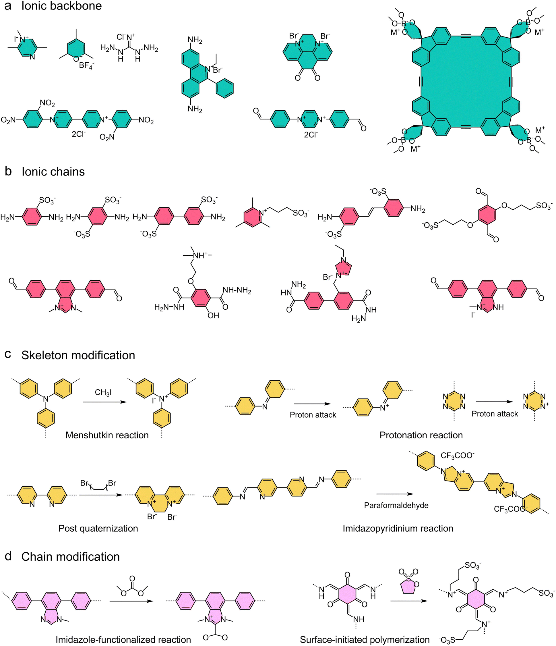 | ||
| Fig. 10 Representative examples of backbones, linkers, and modifications of ionic COFs constructed by bottom-up and post-synthetic modification strategies. (a) Ionic backbone; (b) ionic chain; (c) skeleton modification; (d) chain modification. | ||
In addition, the energy required for ions to overcome various energy barriers to undergo motion in solid materials is defined as the activation energy (Ea) for ion conduction. In general, the Ea in inorganic materials is typically related to the thermodynamic/kinetic barriers, lattice structure, and electrochemical stability. In contrast to inorganic materials, polymers are flexible and can contract or expand accommodating ionic pathways. Notably, the elastic structure of polymers can reduce mechanical energy barriers, but may also bring about other barriers associated with the arrangement of polymer chains.215 For COFs, the Ea of ionic conduction is closely related to pore size, structural stability, and chemical compatibility. Specifically, the pore size of COFs determines the selective transport of ions. To optimize ion transport, the pore size of COFs can be modulated to accommodate ions of different sizes. Moreover, the functional groups of COFs can interact (e.g., hydrogen bonding, electrostatic forces, or π–π interactions) with ions to facilitate or hinder their movement.209 The structural stability of COFs also affects the Ea to some extent. The Ea of ionic conduction can be measured by techniques such as electrochemical impedance spectroscopy (EIS) and further calculated by the Arrhenius equation (eqn (2)).
 | (2) |
In general, COFs demonstrated lower ionic conduction activation energy in comparison to inorganic or polymeric materials because of their distinctive chemical and structural properties. In this regard, ions need to surmount higher energy barriers related to defect sites in inorganic materials, and the randomness of polymer structure creates incoherent paths that can increase the activation energy for ion transport. By precisely controlling the pore size and pore wall functionalization in COFs, the activation energy for ion transport can be effectively reduced.
| σ = n × μ × q | (3) |
The transference number of ions is also an important parameter to quantify the contribution of specific ionic species to the whole ion current. The ion transference number can be calculated in eqn (4).
 | (4) |
4.2.3.1 Monomer and linkage selection. The ion transport in COFs is a complex and multifactorial process. Specifically, the structure and morphology of COFs as well as the nature of ion-COF interactions can significantly affect the ion transport behavior. As we mentioned above, the nature of the chemical structure greatly affects the ion transport properties of COFs.218,219 For instance, the type of monomers and linkages, the functional groups and side chains on the backbone can play an important role in ion transport.
From the perspective of monomer type, Dichtel and coworkers developed a β-ketoenamine-linked DAPH-TFP-COF to modulate Li+ transport (Fig. 11a).220 Briefly, the DAAQ-TFP-COF was synthesized by imine-condensation between 2,6-diaminoanthraquinone (DAAQ) and 1,3,5-triformylphloroglucinol (TFP), and DAPH-TFP-COF was formed at imine-exchange conditions between TFP and benzophenone imine of 2,7-diaminophenazine (DAPH). Notably, the introduction of conductive polymer PEDOT into the DAAQ-TFP nanopores can significantly enhance the electrochemical performance. Due to the higher Li+ diffusion coefficient (DAPH-TFP: 1.1 × 10⁻⁹ cm2 s−1; DAAQ-TFP: 1.6 × 10⁻¹⁰ cm2 s−1), the DAPH-TFP COF exhibited the highest power density and energy density, outperforming both the DAAQ-TFP and PEMOT@DAAQ-TFP COF. Considering the composition of monomers, the redox properties and the diffusion-inducing effect on ions of the phenazine samples were significantly higher than anthraquinone samples. Moreover, Jiang and coworkers synthesized proton-conducting COF materials (TpPa–SO3H, TpBD–SO3H, and TpPa–(SO3H)2) using monomers with different positions and numbers of –SO3H groups.151 Notably, the distance and density of hydrophilic –SO3H groups are critical for proton conduction. For TpPa–SO3H, TpBD–SO3H, and TpPa–(SO3H)2, their –SO3H group distances are 1.4 nm, 1.0 nm, and 0.8 nm, respectively, based on crystal parameter data. Due to the differences in functional groups, these COFs exhibited different proton conduction properties. At 90 °C and 100% RH, TpPa–(SO3H)2 showed the highest proton conductivity of 1389 mS cm−1 due to the lowest –SO3H group distance (0.8 nm). Furthermore, the proton conductivity increased by six-fold when the –SO3H group distance was reduced from 1.4 nm to 1.0 nm.
 | ||
| Fig. 11 Regulation strategies for ion transport in COFs. (a) The chemical structures of DAAQ-TFP-COF and DAPH-TFP-COF. (Reproduced with permission from ref. 220. Copyright 2020, American Chemical Society) (b) The chemical structures of Azo-1 (thiazole), Azo-2 (imine), and Azo-3 (β-ketoenamine) with different linkages. (Reproduced with permission from ref. 221. Copyright 2021, Wiley-VCH) (c) The chemical structures of LiCON-1, LiCON-2, and LiCON-3 with different functional groups and side chains. (Reproduced with permission from ref. 222. Copyright 2020, American Chemical Society). | ||
In terms of the linkage type of COFs, molecular linkers containing heteroatoms are widely used to enhance the wettability of COFs in electrolyte solutions. For example, β-ketoenamine-linked COFs were employed as electrodes or solid-state electrolytes in batteries or capacitors. Thiazole linkage is developed to fulfill the requirements of π-conjugated system and chemical stability. Moreover, the sulfur-containing thiophene, thiazole, and tetrathiafulvalene linkages are found to have superior conductivity and charge mobility. Therefore, to demonstrate the effect of linkage type of COFs on redox reactions, Singh and coworkers demonstrated differences in redox and ionic mobility of three azo-containing COFs linked by thiazole-(Azo-1), imine-(Azo-2), and β-ketoenamine-(Azo-3) (Fig. 11b).221 The Azo-1, Azo-2, and Azo-3 have hexagonal pores with pore diameters of 2.8, 3.0, and 2.7 nm, respectively. For rechargeable lithium-ion batteries, Li+ can be reversibly bound and extracted by the reduction and oxidation of azo groups according to eqn (5).
| R − N = N − R + 2e− + 2Li+ ↔ R − LiN − NLi − R | (5) |
In addition, the COF backbone can be functionalized and modified to produce significant differences in ion transport. In this regard, Loh and coworkers demonstrated the difference in ionic conductivity and ion mobility number of Li-organic batteries with different side-chain functional groups of COF-based solid-state electrolytes (LiCON-1, LiCON-2, and LiCON-3) (Fig. 11c).222 The SD-COF-1 was synthesized by polycondensation between 2,5-bis(allyloxy)-terephthalohydrazide and 2,4,6-triformylphenol. SD-COF-2 and SD-COF-3 were obtained by photochemical thiol–ene click reaction of SD-COF-1 with sodium 2-mercaptoethanesulfonate and 3-mercaptopropanoic acid, respectively. LiCON-1, LiCON-2, and LiCON-3 were obtained by treating SD-COF-1, SD-COF-2, and SD-COF-3 with aqueous lithium carbonate. Due to the differences in side-chain functional groups, LiCONs exhibited significant differences in Li+ conductivity and Li+ mobility number. For example, the conductivities of LiCON-1, LiCON-2, and LiCON-3 were 2.13 × 10⁻⁷, 4.36 × 10⁻⁶, and 3.21 × 10⁻⁵ S cm−1 at 20 °C, respectively. The Li+ mobility numbers of LiCON-1, LiCON-2, and LiCON-3 were 0.86, 0.83, and 0.92 at 20 °C, respectively. Therefore, the use of Li salts from strong acids and anionic groups with stronger acidity can produce higher ionic conductivity and ion mobility numbers.
4.2.3.2 Solvent and salt control. Indeed, the ion transport properties can also be strengthened by improving the concentration or mobility of ions. In this regard, the mobility of ions can be enhanced by the addition of solvents, while the mobile ion concentration can be increased by the addition of salts containing mobile ions.223 Briefly, the dielectric constant of the medium inside the COFs can be altered by the presence of solvent molecules doped into the pores of COFs due to the interaction of solvent molecules with the porous structure of COFs.224 For instance, propylene carbonate (PC) can be employed to dissolve ions in COFs for enhanced ion conductivity. In this process, PC can increase the dielectric constant of the environment surrounding the ions, thereby reducing the Coulombic interactions between the ions and making them easier to transport. Moreover, the interactions generated by the functional groups of COFs and the solvent can change the structural environment of COFs, thus affecting the ion mobility.225 COFs with amine or hydroxyl groups may create hydrogen bonding networks with polar solvents, thereby increasing ion channels. Meanwhile, the solvent can also serve as addition hopping site, which allows for enhanced ion conductivity through different ion conduction paths between the different pores.
In addition, the addition of salts including mobile ions to COFs can increase ion conductivity by improving the concentration of mobile ions. In this regard, Uribe and coworkers achieved a high ion conductivity of 2.6 × 10⁻⁴ S cm−1 by impregnating LiClO4 (Li+ source) in COF-5 at room temperature.226 Similarly, Wang and coworkers doped LiPF6 into CD-COF to obtain a superior ion conductivity of 2.7 × 10⁻³ S cm−1 at room temperature.227 In this process, depending on the interaction with the framework, the salts introduced into the COF pores may remain in the pores as solid particles or may be dissolved or partially dissolved. However, too high concentration of added salt results in reduced ion mobility due to ion aggregation and increased viscosity. Moreover, the lower dissociation energy of salt means that it is easier to dissociate to generate free ions, which contributes to COFs releasing enough energy to break through the high dissociation barrier. Conclusively, the addition of salts to COFs can greatly enhance their ion conductivity due to salt dissociation increases the availability of free ions and provides ion transport pathways.
4.3 Charge transport
C, CN, CO, and phenyl ring) of COF frameworks.232,233 Superior broad light absorption is also exhibited by the strong dipole and intramolecular hydrogen bonding between CO and N–H groups in COF frameworks. In these processes, charge transport in COFs plays a critical role. Generally, electrical conductivity reflects the ability to achieve charge transport in a material and can be expressed as eqn (6).| σ = enμ | (6) |
 | (7) |
An in-depth understanding of the charge-transport capabilities of COFs demands knowledge of the detailed charge-transport mechanism. For COFs, the units are linked by covalent bonds (in-plane direction or xy-plane direction) and the various layers are stacked by van der Waals interactions (out-of-plane direction or z-direction). In general, charge can be transported through coherent tunneling in the xy-plane, and transported through a carrier hopping mechanism in the z-direction.234–236 Indeed, effects to understand the charge transport capabilities of 2D COFs typically rely on the determination of band structures and crystal structures. Moreover, factors such as the packing arrangement and molecular structure of the COF framework can greatly affect the carrier mobility and conductivity.
4.3.2.1 Bottom-up design. In general, the monomer linkages and units of COFs can significantly affect the degree of electronic couplings and π-conjugation between the nearby monomer units, resulting in different charge transport properties.237–239 In this regard, given the strength of the connection between geometric structure and electronic structure of the π-conjugated system in COFs, Jean and coworkers evaluated the charge carrier mobility by considering electronic vibration coupling.240 Notably, COFs are usually constructed based on three-arm cores (e.g., triphenylene and benzene) or four-arm cores (e.g., porphyrins and pyrene). In general, three-arm cores tend to form highly symmetric lattices, which usually result in the occurrence of completely flat top valence bands or bottom conduction bands. In this case, the charge carrier effective mass in COFs is extremely large and the associated carrier mobility is reduced. Therefore, four-arm core COFs (Por-COF, Pyr-COF, and ZnPor-COF) with different monomers were constructed to investigate the differences in charge transport (Fig. 12a). Considering the effect of localized electronic vibrational interactions, the electron mobilities are about 82 cm2 V−1 s−1, 66 cm2 V−1 s−1, and 94 cm2 V−1 s−1 for Por-COF, Pyr-COF, and ZnPor-COF, respectively. Indeed, there is no direct overlap between the frontier orbitals of the pyrene pores and the electronic couplings derived from the mixing of the pyrene frontier with the diacetylene-connected orbitals. The charge transport of both electrons and holes can be regarded as originating in electron/hole transfer between adjacent pyrene units, with the pyrene unit acting as a charge-carrying part. Therefore, the selection of monomers with greater strength of electronic coupling between adjacent core units facilitates electron transport.
 | ||
| Fig. 12 Regulation strategies for charge transport in COFs. (a) The chemical structures of Pyr-COF, Por-COF, and ZnPor-COF. (Reproduced with permission from ref. 240. Copyright 2019, Royal Society of Chemistry) (b) The structures of COF-366, COF-66, and TTF-COF. (Reproduced with permission from ref. 241. Copyright 2011, American Chemical Society) (c) The structures of COFTPAB-DHPA, IL-COFTPAB-DHPA, and Co-COFTPAB-DHPA. (Reproduced with permission from ref. 242. Copyright 2022, Elsevier). | ||
COFs with π-conjugation systems and short layer spacing can generate electronic interactions between different layers.243 Therefore, Yaghi and coworkers created extended planar π-electron systems by choosing porphyrin units to form two COFs (COF-66 and COF-366) with high charge carrier mobility (Fig. 12b).241 The well-defined lamellar structure and arrangement in COFs facilitates the flow of carriers. The charge-carrier conduction of COF-66 and COF-366 was performed by flash photolysis time-resolved microwave conductivity measurements at 25 °C with a maximum value of 1.7 × 10⁻⁵ cm2 V−1 s−1 and 4.1 × 10⁻⁵ cm2 V−1 s−1, respectively. Moreover, the time-of-flight (TOF) transient current integration measurements performed on COF-366 and COF-66/poly(methylmethacrylate) membranes showed 1D hole mobilities of 8.1 cm2 V−1 s−1 and 3.0 cm2 V−1 s−1, respectively. In brief, the comparison between COF-366 and COF-66 demonstrates both the advancement of the porphyrin unit in COFs in electron transport and the difference in electron transport by the linkages of COFs.
4.3.2.2 Post-synthesis design. In addition, the functional groups or side chains in the frameworks of COFs also have a significant effect on their electronic transport. In this regard, Qiao and coworkers prepared COFTAPB-DHPA membranes with customizable shapes by interfacial synthesis, and then further enhanced charge transport by metal coordination (Co2+, Co-COFTAPB-DHPA) and spatial-partitioning (covalent bond with ionic liquid, IL-COFTAPB-DHPA) (Fig. 12c).242 For COFTAPB-DHPA, the fully conjugated π-electron system and stable open mesoporous structure facilitate the ion diffusion to the internal active material interface, thus ensuring rapid charge migration. IL-COFTAPB-DHPA exposed more electrode/electrolyte accessible interface owing to the presence of IL side chains, thus improving the charge accumulation capacity. For Co-COFTAPB-DHPA, electrons can be transferred from the backbone of COFTAPB-DHPA to Co component, providing a high electron cloud density for the active site and thus enhancing the redox activity. Moreover, IL-COFTAPB-DHPA and Co-COFTAPB-DHPA exhibited energy densities of 139.7 mW h cm−3 and 230.4 mW h cm−3 when used as electrodes for capacitors, which also demonstrated the effect of the differences in the functional groups and side chains of COFs on the charge transport and redox properties. It is worth mentioning that some linkages of COFs can disrupt conjugation to the detriment of planar charge transport. For example, imine linkages can provide in-plane π-conjugation, but the inherent polarization of C
N linkages can hinder efficient charge transport to some extent. In addition, diacetylene linkages can deliver stronger electronic coupling compared to phenylene-based linkages, resulting in higher carrier mobilities and smaller effective masses.
For the same type of functional groups and connection types, COFs can be designed into different topologies such as triangular, quadrilateral, hexagonal, honeycomb, Kagome, and heterocellular.84 The arrangement of the building blocks and the resulting symmetry also have a strong influence on the charge transport properties. As we mentioned above, four-arm cores can produce more dispersion bands and a larger effective mass than three-arm cores in Pyr-COFs and Por-COFs.240 Indeed, the highly symmetric structure of COFs can produce flat top valence bands and bottom conduction bands, which can reduce the charge transport efficiency to some extent. In this regard, reducing the symmetry of COFs facilitates charge transport.
Despite the theoretical high inter-layer and intra-layer electronic conductivity of COFs, several limitations still exist: (i) the defects and boundaries between COF crystals may hinder electron transport to some extent; (ii) the diffusion of electrons in COF nanosheets at high currents is limited due to strong π–π interfacial interactions. Moreover, the stability of the active center introduced in the COF framework also has an impact on electron transport. In this regard, achieving stability of the radical intermediates is the key to improving electron transport in COFs.
4.4 Ion/molecule selectivity
4.4.1.1 Size confinement. The size confinement is closely associated with the pore size of the COF membrane. The wide range of pore sizes (from angstroms to nanometers) for COFs endows them with great possibilities and potential for exploiting pore size variations to achieve selectivity. Especially for lithium–sulfur (Li–S) batteries, the COF-based separator can mitigate the polysulfide shuttle effect effectively through size confinement.246 For example, Lee and coworkers synthesized COF-1 (0.7 nm) and COF-5 (2.7 nm) in situ on carbon nanotubes (CNTs) as an intermediate layer between the sulfur cathode separator of Li–S batteries for inhibiting polysulfide shuttling (Fig. 13a).247 Briefly, the COF-1 intermediate layer with microporous features enabled superior ion-selective transport compared to COF-5 with its larger pore size. Notably, the COF-1/CNT interlayer can act as both a barrier layer for polysulfide and a fast channel for ionic conduction, thus creating a synergistic effect within the batteries. Therefore, with the size confinement of COFs, the introduction of COF-1/CNT interlayer significantly improves the capacity retention and cycling performance of Li–S batteries.
 | ||
| Fig. 13 Types of ion/molecule selectivity in COF membranes. (a) COF-1 and COF-5 with different pore sizes achieve selectivity through size confinement. (Reproduced with permission from ref. 247. Copyright 2016, American Chemical Society) (b) Lithiated TpPa–SO3Li/Celgard separator achieves selectivity through electrostatic interactions. (Reproduced with permission from ref. 193. Copyright 2021, American Chemical Society) (c) Short-range interactions induced by different electrostatic potentials (ESP) confer COF-TpPa/PAN, COF-TbPa/PAN, and COF-TaBt/PAN membrane selectivity. (Reproduced with permission from ref. 248. Copyright 2024, Springer Nature). | ||
4.4.1.2 Electrostatic interaction. Electrostatic interactions are an alternative and effective method to realize ion-selective transport in COFs. Specifically, ion selective transport can be realized by electrostatic interactions of charged groups on the COF pore walls, which can be modulated by tuning the charge density of COF functional groups. For example, to achieve rapid anion transport, a positively charged functional group can be grafted onto the framework of COFs to facilitate anion diffusion. In this regard, Sun and coworkers prepared a COF membrane (TpPa–SO3Li) on a commercial separator for Li–S batteries (Fig. 13b).193 Specifically, the well-aligned nanochannels and continuous negative charge sites in TpPa–SO3Li can effectively promote Li+ conduction and inhibit polysulfide diffusion through electrostatic interaction. In this process, the electrostatic interaction originates from the sulfonic acid groups on the COF frameworks. Notably, the TpPa–SO3Li functional layer was fabricated on a commercial Celgard substrate by vacuum-assisted self-assembly and could maintain good mechanical strength after the folding test. Moreover, the superior hindering ability of TpPa–SO3Li to diffuse polysulfide was also demonstrated visually using an H-shaped cell with TpPa–SO3Li/Celgard. Consequently, Li–S batteries using this COF composite separator achieved higher initial capacity and retention.
4.4.1.3 Short-range interactions. The distribution of electrostatic potential (ESP) can be changed by selecting the linkages in the COF membranes, which affects the short-range interactions between the membranes and ions and thus the selectivity of COF membranes. To test this hypothesis, Sun and coworkers synthesized three COF membranes (COF-TpPa/PAN, COF-TbPa/PAN, and COF-TaBt/PAN) with charge-neutral structures using β-ketoenamine, hydrazone, and imine linkages (Fig. 13c).248 Specifically, ESP indicated the variations in the magnitude and distribution of the electrostatic potential between these COF membranes, indicating significant short-range interactions with ions. To elucidate the differences in selectivity of these COF membranes, their conductivities were analyzed over a wide of KCl concentrations. In this regard, COF-TbPa/PAN membranes exhibited lower selectivity due to weak ion adsorption sites. COF-TpPa/PAN membranes exhibited high affinity ion-binding sites and enhanced ion adsorption capacity with increasing ion concentration, thus improving the ion screening effect. In contrast, COF-TaBt/PAN membranes possessed suitable ion-binding sites and their selectivity decreased once the ion concentration exceeded a specific threshold. Indeed, the superior selectivity of COF-TpPa/PAN membranes in KCl solutions is attributed to the strong short-range interactions between Cl− and membranes, which facilitates the transport of K+. As a result, with this excellent permeation selectivity, the COF-TpPa/PAN membrane exhibited prominent permeation energy conversion efficiency.
4.4.2.1 Bottom-up design. As we mentioned above, bottom-up design is an effective and simple method to introduce functional molecules into the COF frameworks. In this regard, target COFs can be accessed by choosing suitable or pre-designed building blocks for polymerization reactions. The type and content of functional groups and the length of molecular chains can be accurately adjusted and evenly distributed in the COF pores. For example, Guo and coworkers fabricated COF-TpBD and COF-TpBD-COOH for coating polypropylene (PP) separators to achieve homogeneous transport and deposition of Li+ through a bottom-up design (Fig. 14a).249 Notably, the abundant negative charge sites in COF-TpBD-COOH can inhibit the free diffusion of lithium salt anions by electrostatic interaction compared with COF-TpBD. In other words, the carboxyl groups in the COF framework can act as ionic sieves, hindering the migration of anions and promoting the homogenization of Li+ transport, thus exhibiting excellent selectivity. As a consequence, the COF-TpBD-COOH-coated PP separator can significantly inhibit the dendrite generation in lithium-ion batteries, resulting in a higher electrochemical performance.
 | ||
| Fig. 14 Construction strategies for ion/molecule selectivity in COFs. (a) Introducing functional groups and molecular chains on COF frameworks by bottom-up design strategy. (Reproduced with permission from ref. 249. Copyright 2022, Wiley-VCH) (reproduced with permission from ref. 250. Copyright 2024, PNAS. ORG) (b) Introducing molecular chains and metal ions on COF frameworks by post-synthetic design strategy. (Reproduced with permission from ref. 251. Copyright 2022, Springer Nature) (reproduced with permission from ref. 193. Copyright 2021, American Chemical Society). | ||
In addition to controlling the type of functional group, selectivity can be achieved by adjusting the length of the molecular chain on the COF framework through a bottom-up design. Sun and coworkers synthesized COF membranes with different oligoether segment lengths for specific selectivity towards Li+ and Mg2+ (Fig. 14a).250 Notably, the incorporation of oligoethers in COF membranes can significantly enhance Li+ conductivity and improve the separation efficiency between Li+ and Mg2+ compared to membranes without oligoethers. Indeed, the selectivity of these COF membranes arose from the length of the oligoether chain within the pore versus the energy barrier for ion partitioning into the pore. It is worth noting that oligoethers containing different amounts of ethylene oxide (EO) units have different solubility and flexibility, thus affecting the barrier to ion transport within the membrane. Among the COF membranes with different lengths of EO units, increasing the length of EO units facilitated ion transport, whereas the COF membranes with two EO units showed the strongest selectivity between Li+ and Mg2+. Therefore, the introduction of functional groups or functional side chains within the COF framework through a bottom-up strategy can effectively modulate the selectivity of COFs.
4.4.2.2 Post-synthesis design. The introduction of functional groups by bottom-up method can influence the crystallinity of COFs, resulting in the inability to synthesize some ion-selective COFs. Therefore, the post-synthesis design brings new possibilities for the creation of novel ion-selective COFs. For example, Lai and coworkers converted a vinyl-containing COF membrane (COF-V) into cysteine-functionalized COF membrane (COF-Cys) with specific ion-selectivity by post-synthesis design (Fig. 14b).251 In this process, the cysteine functional groups were grafted onto the framework of COF-V by a fast thiol–ene click reaction. Notably, cysteine can act as an ion-selective switch in response to external stimuli. Therefore, the ion selectivity of COF-Cys membrane is dynamic and can be switched between Na+ and K+ selectivity by applying a pH stimulus. Specifically, the permeability of COF-Cys membrane to K+ and Na+ was 21.4 and 12.6 mmol h−1 m−2 at pH 3.8, respectively, the COF-Cys membrane exhibited selective transport of K+. In contrast, the Na+ flux of the COF-Cys membrane increased to 73.7 mmol h−1 m−2 when the solution pH was increased to 8.9, while the K+ flux remained at 27.3 mmol h−1 m−2. Moreover, changing the pH of the solution did not reverse the K+/Na+ selectivity of the COF-V membrane, suggesting that reversible ligand interactions between the cysteine molecules and target ions facilitate the switchable K+/Na+ selectivity in COF-Cys membrane. Apart from introducing functional groups into the framework of COF by post-synthesis, specific ions can also be introduced to achieve ion selectivity. As we mentioned above, Sun and coworkers converted TpPa–SO3H into TpPa–SO3Li by post-synthesis for achieving selective transport of Li+ and polysulfides.193
It can be said that the bottom-up and post-synthesis design can effectively bind the target ions or molecules to the framework of COFs to achieve innovative selectivity. The selectivity of COFs is highly dependent on the characteristics of the pore environment, and thus the relationship between pore properties (e.g., size, functional group type/density, and molecular chain type/length) and ion-selective transport still needs to be further explored.
4.5 Mechanical property
Mechanical properties, one of the most important factors in the application of COF membranes, are highly related to efficient and stable ion/electron transport.252–254 Especially in energy storage and conversion applications, COF membranes used as solid electrolytes, electrode protection layers, flexible electrodes, or ion transport media are required to have excellent mechanical properties to cope with complex environmental variations and achieve long-term operational durability. That is, the excellent mechanical properties of COF membranes are a prerequisite for their successful application. In this section, we simplify the types of COF membrane into pure COF membrane and COF composite membrane, and explore the key strategies for enhancing the mechanical properties of COF membrane through representative examples in energy storage and conversion.4.5.2.1 One-step preparation of pure COF membranes. Generally, COFs synthesized by hydrothermal/solvothermal are in powder form. Therefore, the conversion of COF powders into membranes is a key concern of COF community. In Section 3.2, we have summarized and discussed in detail the various methods of preparing COF membranes. Indeed, the mechanical properties of COF membranes are largely dependent on the preparation method and modulation strategy of COF membranes. The pure COF membranes are usually prepared by interfacial polymerization (IP). Notably, the IP technology for preparing non-ionic COF membranes is difficult to transfer directly to the construction of ionic COF membranes for electrochemical energy storage and conversion because monomers with multiple ionic groups typically display extremely low reactivity due to the strong steric hindrance effects and electron-withdrawing of ionic groups. In this regard, the proper activation of ionic monomers is the key to prepare ionic COF membranes with high mechanical properties in one step using IP technology. Therefore, Zhang and coworkers used Brønsted acid to activate the aldehyde monomer in the organic phase and Brønsted base to activate the ionic amine monomer in the aqueous phase to prepare TpBD–(SO3H)2 COF membranes for fuel cells with excellent mechanical properties in one step by IP (Fig. 15a).258 Briefly, Brønsted acid can convert –CHO into cation –C+HOH, and Brønsted base can convert –NH3+ into –NH2. After double activation, the Schiff base reaction at the aqueous–organic interface was significantly accelerated, resulting in ionic COF membranes with high mechanical properties and highly crystalline. Notably, the Fukui function is employed as a descriptor to compare the reactivity of monomers with different numbers of ion groups. During the activation process, both the aldehyde monomer and the amine monomer are accompanied by a significant change in the Fukui function, which greatly affects the course of the Schiff base reaction and thus improves the mechanical properties of COF membranes. That is, the rational activation of reactive monomers to enhance the polymerization reaction rate contributes to the one-step construction of COF membranes with superior mechanical properties (20 MPa) using IP, which also ensures the research and application of pure COF membrane as high-performance proton exchange membranes in fuel cells. Similarly, this monomer-activated strategy was also used to prepare 3D COF membranes with high mechanical properties. For example, Jiang and coworkers described the preparation of 3D COF membranes with high mechanical properties using a dual acid-mediated IP strategy for stable and efficient ion transport.259 Specifically, the aldehyde monomer used to synthesize 3D COF was dissolved in aqueous acetic acid, while the amine monomer was dissolved in octanoic acid. The organic phase containing amine monomers was then slowly added to the top of the aqueous phase containing aldehyde monomers and kept under undisturbed conditions for 3 days to form a stable and transferrable COF membrane. Notably, the formed 3D COF membrane has a high Young's modulus (2.4 GPa) and excellent wet/dry stability, which ensures the stable operation of the COF membrane as a proton exchange membrane and osmotic energy conversion membrane. In this regard, the double acid-mediated polymerization strategy is a decisive factor in the synthesis of COF membranes with high mechanical properties.
 | ||
| Fig. 15 Strategies for constructing pure COF membranes with high mechanical strength. (a) One-step fabrication of COF membranes with high mechanical properties using dual-activated interfacial polymerization and the corresponding mechanical properties. (Reproduced with permission from ref. 258. Copyright 2022, Springer Nature) (b) The synthesis process and nano-indentation measurement result of FCOF membrane. (Reproduced with permission from ref. 260. Copyright 2021, Springer Nature) (c) Two-step preparation of IPC-COF membranes with high mechanical properties using vacuum filtration self-assembly and the corresponding mechanical properties. (Reproduced with permission from ref. 150. Copyright 2020, Wiley-VCH). | ||
In addition, COF membranes with high mechanical strength and flexibility provide new opportunities for the construction of metal anode protection layers for rechargeable batteries. In general, the protective layer as a metal anode requires excellent mechanical properties (elastic modulus >30 GPa) to effectively prevent the generation of metal dendrites and buffer the volume expansion of the metal anode during the cycling process. In this regard, Guo and coworkers developed an ultrathin and high mechanical strength fluorinated 2D COF membrane (FCOF) as a protective layer on the surface of Zn anodes for aqueous Zn ion batteries (Fig. 15b).260 Briefly, a continuous FCOF membrane was fabricated by solvothermal method on tube walls by dissolving the monomers in a dioxane/mesitylene mixture with acetic acid as a catalyst. Notably, the FCOF membrane can adhere tightly to the surface of Zn foil due to its excellent flexibility and mechanical properties. Specifically, nano-indentation measurements showed that the elastic modulus of FCOF membrane exceeded 30 GPa and the hardness exceeded 1.2 GPa, which is a prerequisite for the FCOF membrane to play the role of ion modulation to protect the stable operation of Zn anode. In other words, the good mechanical strength of FCOF membrane is beneficial in buffering volume expansion and retarding dendrite extension during dissolution/deposition of Zn anodes.
4.5.2.2 Two-step preparation of pure COF membranes. Notably, the strategy of IP can also be utilized to directly synthesize COF nanosheets and pure COF membranes with high mechanical properties can be obtained by vacuum-assisted self-assembly (two-step preparation of pure COF membranes). For example, Jiang and coworkers developed a bottom-up approach to synthesize IPC-COF nanosheets in aqueous solution through diffusion and solvent co-mediated conditioning and prepared IPC-COF membranes with ultra-high mechanical properties (91.2 MPa) via vacuum-assisted self-assembly (Fig. 15c).150 Indeed, the ordered structure between IPC-COF nanosheets and the interfacial interactions induced by vacuum filtration contribute to such high mechanical strength. Meanwhile, the excellent mechanical properties of IPC-COF membranes also ensure their stable operation as proton exchange membranes for fuel cells.
4.5.2.3 Monomer pre-functionalization to prepare COF composite membranes. In addition to some strategies that can be directly prepared into pure COF membranes, COF composite membranes with high mechanical strength have also been developed. For example, Zhang and coworkers grafted flexible poly(ethylene glycol) (PEG) onto reactive monomers and prepared COF membranes (PEG-COF) with superior mechanical properties and flexibility through IP (Fig. 16a).261 Notably, the fracture stress and strain of the pristine COF-42 membrane were 0.1 MPa and 5.0%, respectively, and their mechanical properties (21 MPa) were greatly improved after combining with PEG in one system (PEG-COF-4). Specifically, COF-42 membranes without PEG molecules are formed from loose COF particles and have low mechanical strength. The flexible PEG chains introduced into the COF-42 framework can be intertwined with each other, resulting in higher ultimate stress and Young's modulus of the synthesized COF membrane, which effectively ensures the application of COF composite membranes in humidity-responsive power generation. In this process, the length of PEG chains doped into the COF framework also had a significant effect on the mechanical properties of the COF composite membrane.
 | ||
| Fig. 16 Strategies for constructing COF composite membranes with high mechanical strength. (a) The preparation process and mechanical properties of PEG-COF composite membrane. (Reproduced with permission from ref. 261. Copyright 2022, Wiley-VCH) (b) The preparation process and mechanical properties of CON-2(SO3H)@CS composite membrane. (Reproduced with permission from ref. 153. Copyright 2023, Wiley-VCH) (c) The preparation process and mechanical properties of SPEEK/TpBd-Cx-SO3H composite membrane. (Reproduced with permission from ref. 262. Copyright 2024, Royal Society of Chemistry). | ||
4.5.2.4 Assembly of nanosheets to prepare COF composite membranes. 2D materials have received extensive and enthusiastic attention in membrane applications because of their unique spatial structure and ion transport behavior. As we mentioned above, 2D COF nanosheets can be easily acquired by employing IP. In addition to the direct assembly of COF nanosheets into membranes, the introduction of 1D or 2D materials to assist or strengthen the interaction force between nanosheets is a common strategy for the preparation of nanosheet-based COF composite membranes. From the perspective of the mechanical properties of COF composite membranes, such assembly triggered by solution removal helps to fully utilize the structural advantages among the components to prepare COF composite membranes with high mechanical properties, which is especially important for COF-based solid-state electrolytes or other ion transport membranes. For example, Tang and coworkers prepared COF composite membranes with high mechanical strength (95 MPa) by vacuum-assisted self-assembly of positively charged chitosan and negatively charged COF nanosheets [CON-2(SO3)] for fuel cells (Fig. 16b).153 Notably, the strong electrostatic interactions between chitosan and CON-2(SO3) nanosheets triggered by water removal during assembly are the source of such excellent mechanical properties. With such excellent mechanical property-derived structural stability, the prepared CON-2(SO3)@CS composite membrane exhibited remarkable durability in fuel cells. Similarly, 1D silk nanofibers (SNFs) have been reported to be designed as nano-binders to connect COF nanosheets (TpPa–SO3H) into robust COF composite membranes for fuel cells by vacuum-assisted self-assembly.263 As the content of COF nanosheets increases, the mechanical properties of COF/SNF composite membrane can reach up to 141 MPa, which is mainly attributed to the abundant interfacial hydrogen bonding interactions and physical entanglement between 2D COF nanosheets and 1D SNF.
4.5.2.5 Filling into polymers to prepare COF composite membranes. Filling COFs into a polymer matrix by solvent evaporation is a conventional method for preparing COF composite membranes and has been widely developed and studied for energy storage and conversion applications due to its simplicity and scalability. In this regard, Jiang and coworkers introduced COF with tunable side chain lengths (TpBd-Cx-SO3H) into sulfonated poly(ether ether ketone) to prepare proton exchange membranes for fuel cells using the casting method (Fig. 16c).262 It is worth noting that the rigid framework and flexible side chains of TpBd-Cx-SO3H together strengthen the hydrogen bonding interactions polymer matrix, thereby forming a membrane with exceptional mechanical strength (120.41 MPa). That is, the excellent mechanical strength ensures high stability and integrity of COF membranes in fuel cell components, contributing to excellent operational durability and safety. Along a similar research path, Yang and coworkers prepared a robust and self-standing COF composite membrane (polyCOM) for fuel cells using solvent evaporation by in situ incorporation of hyperbranched polyethylenimine (HPEI) into COFs.264 Specifically, HPEI can crosslink the adjacent COF particles and enhance their interactions, giving polyCOM excellent structural capabilities and mechanical properties. Notably, the tensile strength of polyCOM can reach up to 45.4 MPa, which is 2.4 times higher than that of the TpPa–SO3H membrane (13.26 MPa). In brief, the rigidity and flexibility of COF membranes can be significantly enhanced by in situ introduction of polymers, which improves the durability of COF membranes against external environmental stimuli. Noteworthy, from the perspective of mechanical properties, the mechanical properties of COF composite membranes are mainly dependent on the polymer matrix, and the filled or introduced COFs act as reinforcing agents to a large extent.
4.6 Crystallinity
4.6.2.1 Porous substrate assistance. Direct crystallization of COF membranes on porous substrate is essential for the industrial application of this novel membrane technology. In general, the crystallinity of COF membranes fabricated by conventional liquid–liquid IP and substrate-assisted preparation was relatively low. In this regard, Zhu and coworkers prepared a highly crystalline COF membrane (COF-DT) on a porous substrate by contra-diffusion IP (Fig. 17a).268 Briefly, the oil phase containing DMTP and the water phase including TAPB and HAc were separated by the PAN on the two sides of a diffusion cell. Notably, the hydrolyzed PAN support could act as a moderator because of its hydrophilic surface, allowing TAPB to diffuse slowly from the aqueous phase to the oil phase. Therefore, a distinct yellow COF layer appeared on the surface of PAN with a diameter of about 3.5 cm after 72 hours, and self-supported and highly crystalline COF-DT membranes were obtained by dissolving PAN in DMF.
 | ||
| Fig. 17 Strategies for constructing COF membranes with high crystallinity. (a) Schematic representation of the process of growing highly crystalline COF-DT membrane on porous PAN support via IP. (Reproduced with permission from ref. 268. Copyright 2023, Royal Society of Chemistry) (b) Schematic diagram of the preparation process of highly crystalline TFB-TAPB membrane by microwave-assisted method. (Reproduced with permission from ref. 269. Copyright 2024, Wiley-VCH) (c) Schematic diagram of the fabrication of highly crystalline COF membrane using phase transition (reproduced with permission from ref. 270. Copyright 2022, Springer Nature). | ||
Along a similar design approach, Jiang and coworkers designed a Brønsted acid-mediated method to fabricate TFP-HZ COF membranes with high crystallinity by IP on porous PAN substrates.271 Notably, as a versatile medium, Brønsted acid can catalyze imine exchange reactions and facilitate the crystallization process of COF membranes. Indeed, the key to substrate-assisted preparation of COF membranes was to induce condensation reactions near the surface of the PAN substrate. For instance, when a hydrophobic precursor was added to the PAN surface, the hydrophobic solvent would not penetrate the nanopores of the PAN because of surface tension. Therefore, the reaction zone of COF membrane can be maintained on the surface of PAN substrate. Similarly, Wang and coworkers reported the utilization of a substrate surface for the positioning of the water-oil interface in the synthesis of COF membranes.272 For example, the hydrophobic PVDF substrate has been demonstrated to impede the penetration of aqueous solutions, whereas the hydrophilic substrate has been shown to prevent the penetration of organic solutions.
4.6.2.2 Microwave assistance. Indeed, the random movement of nanoparticles/monomers usually results in the creation of low-crystalline and loose membranes. To fabricate COF membranes with high crystallinity, disordered-to-ordered strategies have been developed to prepare crystalline COF membranes. Notably, the preparation of COF membranes with high crystallinity requires a substantial input of energy to overcome the energy barriers that accompany the transition from a disordered to an ordered state. In other words, this process usually involves heating or other forms of energy input to promote structural self-repair and rearrangement.
Microwaves are a prevalent form of electromagnetic energy characterized by strong penetration and high heating efficiency, which allows reactants to overcome activation energy barriers more quickly, thus accelerating the reaction rate. Therefore, to prepare COF membranes with high crystallinity, Jiang and coworkers reported a microwave-assisted fabrication method for highly crystalline COF membranes (Fig. 17b).269 Specifically, the first step involves a typical in situ growth process, during which the substrate is submerged in a mixed solution of reactive monomers and catalysts, thereby facilitating expeditious in situ polymerization at room temperature to generate an amorphous pristine membrane. The second step comprises microwave-assisted crystallization, whereby the pristine membrane absorbs microwave energy due to its high dissipation factor. In particular, in the second process, the energy provided by the microwave can enhance the rate of the reversible Schiff base reaction, facilitate structural self-repairing, and accelerate the transformation of the membrane from disordered to ordered structure, enabling the formation of a thermodynamically stable crystalline COF membrane. Moreover, the nanoindentation technique also demonstrated the excellent mechanical properties of crystalline TFB-TAPB membranes prepared by microwave-assisted preparation.
4.6.2.3 Phase switching. In general, COF membranes are mainly prepared via a one-step procedure in liquid phases (interfacial polymerization or in situ solvothermal) through the integration of highly coupled polymerization and crystallization procedures. Notably, controlling the simultaneous crystallization and polymerization that occurs during COF membrane formation in liquids is highly challenging, mainly because of the high surface tension and high viscosity of the liquids that make the removal of by-products from the reaction site extremely difficult. In addition, the random movement of the monomer molecules in the liquid phase results in the generation of low-crystallinity COF membranes. Therefore, Jiang and coworkers presented a strategy to prepare COF membranes with high crystallinity by phase switching (Fig. 17c).270 Specifically, a mixed solution containing aldehyde and amine monomers was cast onto the indium tin oxide (ITO) and subjected to a polymerization process in the presence of solvent and catalyst after solvent evaporation to obtain highly crystalline COF membranes. The temperature in this process was maintained at 60 °C to utilize the reversibility of the imine linkages, and the formed membrane was converted to a highly crystalline COF membrane by bond rearrangement in the gas phase at 145 °C. Further, the free-standing COF membrane could be obtained by etching the ITO layer. Notably, high crystallinity COF membranes can be obtained by the two-step process (decoupling polymerization and crystallization) compared to the common liquid-phase one-step process (polymerization and crystallization occur simultaneously).
4.6.2.4 Monomer activation. As we mentioned above, activation of the reactive monomers using catalysts can effectively control the rate of polymerization, which can regulate the morphology of the formed COFs or COF membranes. In this regard, Zhang and coworkers used Brønsted acid to activate the aldehyde monomer in the organic phase and Brønsted base to activate the ionic amine monomer in the aqueous phase to prepare COF membranes with high crystalline in one step with the help of interfacial polymerization strategy.258 By concurrently activating the ionic amine monomers in the aqueous phase and the aldehyde monomers in the organic phase during IP, the Schiff base reaction at the organic-aqueous interface was accelerated remarkably. Similarly, Wang and coworkers proposed a monomer pre-assembly process to fabricate high crystallinity COF membranes using a surfactant-assisted interfacial polymerization (SAIP).273 Amphiphilic surfactant self-assembles chains across the interface aggregate and pre-assembles monomers and enhances interphase transport of monomers, leading to complete topological growth. It is noteworthy that the crystallinity and pore uniformity of the formed COF membrane have been greatly improved in addition to the reduction of the polymerization time from 72 to 48 hours.
4.7 Stability
4.7.2.1 Selection and conversion of linkage. The stability of COF membranes is dependent on the strength of their linkages, which can be substantially improved by converting weak connections to more robust alternatives by direct or post-synthetic methods. For example, stable COFs can be obtained by converting imine bonds to β-ketoenamine linkages via irreversible enol-to-keto conversion. In this process, the disappearance of easily protonated C
N bonds and the incorporation of irreversible reaction endow the framework with resistance to proton molecular attack. For example, the TpAzo with keto-enamine configuration retains its original structure after treatment with strong acids (9 M HCl). Moreover, the incorporation of bulky alkyl groups into the pores of COFs can also be effective in enhancing stability. The TpPa-2 synthesized from the condensation of Tp and Pa-2 shows superior resistance towards 9 M NaOH. Similarly, Dichtel and coworkers proposed that β-ketoenamine-linked COFs synthesized by monomer exchange reaction have higher stability and crystallinity compared to those formed by direct condensation.275 The prepared COFs maintained high crystallinity under acidic (9 M HCl), basic conditions (9 M NaOH), and boiling water.
Post-synthetic modifications with topological arrangement flexibility permit the incorporation of multiple functional groups or linkers into COFs without disrupting the periodic structure. In this regard, Liu and coworkers reported the conversion of imine-based COFs into stable aromatic frameworks by fixing the reversible imine linkages via a post-synthetic approach (Fig. 18a).60 A series of quinoline-linked COFs with high stability were obtained by an aza-Diels–Alder cycloaddition reaction between arylalkynes and aryl imines. This is attributed to the conversion into a more robust quinoline unit through kinetic fixation. Similarly, Dong and coworkers prepared quinoline-linked COFs with high crystallinity and stability by three-component one-pot in situ Povarov reactions.276 Notably, the obtained COFs have the same structure as those obtained by performing post-synthetic modification methods. Moreover, Yaghi and coworkers prepared amide-linked COFs with excellent stability by direct oxidation of imine-linked frameworks.58 Notably, the XRD patterns of oxidized COFs did not change significantly after 24 h of immersion in 12 M HCl and 1 M NaOH, whereas the imine-linked COFs became amorphous. Additionally, Lotsch and coworkers reported a significant enhancement of the stability of COFs by chemically converting imine bonds to thiazole bonds via a sulfur-assisted locking strategy.57 Notably, thiazole-based COFs are more resistant to acids and bases compared to imine-based COFs and are even effective against hydrazine and sodium borohydride.
 | ||
| Fig. 18 Strategies for constructing highly chemically stable COFs. (a) Schematic representation of the conversion of pristine COF-1 to MF-1 by aza-Diels–Alder reaction and XRD patterns after treatment with various reagents. (Reproduced with permission from ref. 60. Copyright 2018, Springer Nature) (b) Schematic diagram of DmaTph and DhaTph condensed from Tph and Dma/Dha and XRD patterns after treatment in HCl and boiling water. (Reproduced with permission from ref. 277. Copyright 2023, Wiley-VCH) (c) The chemical structure of CCOF-H and CCOF-CMe3 and the XRD patterns after treatment in boiling water, NaOH, and HCl. (Reproduced with permission from ref. 278. Copyright 2017, American Chemical Society). | ||
4.7.2.2 Reinforcement of interlayer interaction. Another way to enhance the stability of COFs is to enhance the interlayer interactions of COFs, which can be modified by intra-layer or inter-layer hydrogen bonding and resonance effects.279 In this regard, Banerjee and coworkers demonstrated that the integration of hydroxyl functional groups adjacent to the imine-based COFs can enhance their chemical stability in acid conditions (Fig. 18b).277 The addition of –OH functional groups around the Schiff base center of COFs can form intramolecular hydrogen bonds to protect the basic imine nitrogen from hydrolysis under the presence of acid and water. Therefore, the obtained COFs showed excellent stability in 3 M HCl due to the reduced nucleophilicity of the imine bond and the post-synthetic modification strategy. Similarly, Liu and coworkers integrated intramolecular hydrogen bonding into the azine-linked COFs making them stable not only at 400 °C but also in methanol, NaOH (1 M), HCl (1 M), and THF solutions for 6 h at room temperature.280 Moreover, Banerjee and coworkers synthesized hollow spherical COFs with intramolecular hydrogen bonding by a self-template synthesis method with superior chemical stability in water and HCl (3 M).281 Subsequently, Jiang and coworkers presented an interlayer strategy using hydrogen bonding to lock COFs for achieving outstanding stability.282 The three-component condensation system is employed to increase the content of hydrogen bonding sites, which gives COFs with planar conformation and trans-imine bonds.
In general, the polarization of CN bonds in COFs may lead to electrostatic repulsion, which negatively affects the stability of COFs. Therefore, Jiang and coworkers proposed a resonance effect strategy by incorporating electron-donating groups (e.g., –CH3, –OCH3, –SCH3) to weaken the polarization effect. Briefly, the lone pairs are separated from the electron-donating groups on the central phenyl ring by resonance effects, thus strengthening the interlayer interactions. Subsequently, this concept was used to synthesize highly stable TPB-DMTP-COF by employing dimethoxyterephthaldehyde (DMTP) as linker and TPB as knot.283 With the presence of the –OCH3 groups, the obtained TPB-DMTP-COF could maintain superior stability in water (25 and 100 °C), organic solvents, NaOH (14 M), and HCl (12 M). Further, the synthesized COFs (TAPB-BMTTPA-COF) have higher stability under strong acid and base conditions by replacing the –OCH3 group with –SCH3 group.284 Notably, the treatment with boiling water, HCl (6 M), NaOH (6 M), and hexane for 3 d hardly affect the crystallinity and porosity of synthesized COFs.
4.7.2.3 Construction of hydrophobic pore surface. Additionally, the hydrophobicity of the COF pore environment can also contribute to the hydrolytic stability of COFs by effectively resisting the erosion of water molecules. For example, Lavigne and coworkers introduced alkyl chains into the boronate ester-linked COFs to enhance their stability in aqueous environments.107 In this regard, the hydrophobicity produced by the alkylation of longer alkyl chains can greatly slow down the invasion of water molecules, thus reducing the rate of hydrolysis. Along the same research path, Cui and coworkers developed alkylated chiral COFs (CCOFs) with high chemical stability by incorporating tert-butyl groups into the pore walls of COFs (Fig. 18c).278 Interestingly, the alkylated COFs were stable in both 9 M NaOH and 1 M HCl solutions, whereas the non-alkylated COFs were not stable under the same conditions. Moreover, olefin-linked COFs (COF-701) fabricated by aldol condensation are another example of stabilization benefiting from hydrophobicity. Briefly, the hydrophobic nature and low polarity of olefin linkages give COF-701 exceptional stability under harsh conditions. Therefore, the formation of hydrophobic pore surfaces by direct synthesis or post-modification can protect COFs to a certain extent from the external environment.
Moreover, the electrochemical stability of COFs during energy storage and conversion also deserves special attention. In this regard, Long and coworkers demonstrated that methyl-modified COFs (DAF-COF) have higher electrochemical stability as catalysts for redox reactions.285 Kim and coworkers developed fluorine-rich COFs as electrode material for potassium ion batteries with enhanced electrochemical stability and performance.286 In this process, the introduction of fluorine atoms not only stabilized the embedding kinetics of K+ but also enhanced their electron affinity/conductivity and improved the reversibility of bond transitions in the charge/discharge cycle, thus enhancing the electrochemical stability of COFs. Huang and coworkers presented a Ni-phthalocyanine-based COF (NiPc-Im-COF) linked by stable imidazole structural units with excellent electrochemical stability in electrocatalytic carbon dioxide.287 Indeed, the electrochemical stability of COFs is closely related to the chemical/thermal/mechanical stability and can also be enhanced by rational selection and modification of the frameworks.
Generally, the boroxine-linked COFs were highly sensitive to water, bases, acids, alcohols, and atmospheric humidity. Other representative COFs such as triazine (CTF-1), imine (COF-300), β-ketoenamine (TpPa-2), hydrazone (COF-42), polyimide (PI-COF-5), spiroborate (ICOF-2), acrylonitrile (Sp2c-COF), ester (COF-119), amine (rPI-3) exhibited satisfactory stability due to the increased strength of chemical bonds compared to boron-based linkages. The representative connection types of COFs and their crystallinity, thermal stability, and chemical stability are summarized in Fig. 19 and the reported stability date is summarized in Table 2.
 | ||
| Fig. 19 Stability of COFs about linkage bonds. Schematic diagram of the (a) development timeline of representative COFs and their corresponding (b) connection types and (c) stability. | ||
| Linkage | COFs | H2O | Acid | Alkali | Ref. |
|---|---|---|---|---|---|
| “×” represents the reported COF material showing an unstable state in this case. “—” represents the reported COF material is unknown in this case. | |||||
| Boroxine | COF-1 | × | × | × | 107 |
| APTES-COF-1 | — | × | × | 61 | |
| Boronate ester | sp3 hybridized ICOFs | Water (2 d) | — | 6 M LiOH (1 d) | 29 |
| Imine | TPB-TP-COF | — | 12 M HCl × | 1 M NaOH × | 58 |
| TPB-DMTP-COF | Boiling water (7 d) | 12 M HCl (7 d) | 14 M NaOH (7 d) | 283 | |
| BND-TFB-COF | Boiling water (2 d) | 9 M HCl × | 9 M NaOH × | 275 | |
| Hydrazone | TpODH | Boiling water (2 d) | 9 M HCl (2 d) | 9 M NaOH | 115 |
| β-Ketoenamine | TpPa-1 | Boiling water (7 d) | 9 M HCl (7 d) | 9 M NaOH × | 183 |
| Tp-Azo-COF | — | 9 M HCl (7 d) | 6 M NaOH | 189 | |
| 3PD | 50 °C water (7 d) | 9 M HCl (7 d) | 9 M NaOH | 122 | |
| Olefin | sp2C-COF-1/2/3 | Water (7 d) | 12 M HCl (7 d) | 14 M NaOH (7 d) | 288 |
| COF-701 | — | 12.1 M HCl (1 d) | Saturated KOH (1 d) | 289 | |
| Por-sp2c-COF | Boiling water (1 d) | 9 M HCl (1 d) | 9 M NaOH (1 d) | 290 | |
| 1,4-Dioxin | JUC-505 JUC-506 | Boiling water (7 d) | 12 M HCl (7 d) | 14 M NaOH (7 d) | 125 |
| COF-316 | — | 12 M HCl (3 d) | 6 M NaOH | 291 | |
| Imidazole | LZU-501 | Water (3 d) | 9 M HCl (3 d) | 9 M NaOH (3 d) | 126 |
| Oxazole | LZU-190 | Boiling water (3 d) | 9 M HCl (3 d) | 9 M NaOH (3 d) | 127 |
| Thiazole | COF-921 | — | 12.1 M HCl | 10 M NaOH (1 d) | 292 |
| TTT-COF | — | 12.5 M HCl (16 h) | 12 M NaOH (16 h) | 57 | |
| Azine | Py-Azine COF | Water (1 d) | 1 M HCl (1 d) | 1 M NaOH (1 d) | 293 |
| Triazine | CTF-DCBT | Boiling water | 4 M HCl | 4 M NaOH | 294 |
| Imide | TfpBDH | Water | 3 M HCl × | — | 295 |
| Phenazine | CS-COF | — | 1 M HCl | 1 M NaOH | 296 |
| Pyrazin | PZ-COF | — | 1 M HCl | 1 M NaOH | 297 |
| Amide | CAF-1/2 | Boiling water | 12 M HCl | 14 M NaOH | 298 |
4.8 Interface connectivity
In several energy storage applications (take the examples of COF-based solid electrolyte or electrode protection layer for aqueous zinc ion batteries), COF membranes as ion transport media can be used to achieve excellent and stable electrode interface chemistry by modulating functional groups or preparation methods.In this regard, COF membranes can improve interfacial compatibility by introducing polymers to establish adhesive interfacial contacts (Fig. 20a). For example, Lan and coworkers prepared zine anode protection membranes for aqueous zinc ion batteries by solvent evaporation of COFs with zincophilic properties and polyvinyl chloride (PVC).299 Due to the excellent adhesion of PVC, the formed PVC-Zn-AAn-COF composite membrane can be tightly and reproducibly adhered to the zinc foil, effectively reducing the contact resistance between the PVC-Zn-AAn-COF composite membrane and zinc anode. Moreover, the interfacial compatibility of COF membranes with metal anode can also be effectively enhanced by growing the COF membranes directly on the metal anode (Fig. 20b). For instance, Grzybowski and coworkers synthesized COF membranes on zinc anode surfaces for the inhibition of surface corrosion and growth of large zine dendrites by a direct and scalable self-assembled dip-coating technique.300 Notably, the thickness and stiffness of COF membrane increased with the growth time. Unlike micron-sized polymer membranes, COF membranes have a low degree of expansion when in contact with the electrolyte, contributing to a reduction in structural failure and performance degradation due to volume expansion. Moreover, the COF membranes were self-assembled in situ directly on the zinc anode, resulting in excellent interfacial connectivity between COF membranes and zinc anode, which can significantly inhibit the dendrite growth and the formation of electrochemically inactive zinc by-products. In addition, excellent interfacial connectivity can also be achieved by transferring the pre-synthesized COF membranes onto the metal anode (Fig. 20c). In this regard, Guo and coworkers developed a fluorinated COF membrane (FCOF) as a protective layer for zinc anodes.260 Notably, the FCOF@Zn anode was fabricated from Zn foil by drawing in acetone solvent. In particular, the FCOF membrane can adhere tightly to the surface of zinc foil after drying and will not detach even under unfolding, bending, or rolling of zinc, which also demonstrates the excellent interfacial connectivity between the FCOF membranes and zinc foil and ensures the tight contact between the components. As a result, the zinc deposits show horizontally aligned lamellar morphology as well as achieving ultra-high stability of FCOF@Zn symmetric battery.
 | ||
| Fig. 20 Strategies for constructing interfacial connectivity of COF membranes. (a) Schematic diagram of the synthesized COF particles blended with polymer matrix to achieve excellent interfacial adhesion; (b) schematic diagram of excellent interfacial compatibility achieved by direct preparation of COF membrane on the metal anode; (c) schematic diagram of transferring COF membrane to the metal anode to achieve excellent interfacial compatibility. | ||
From another perspective, the interfacial compatibility between COFs and polymer substrates in COF composite membranes also deserves special attention. In this regard, COFs have been shown to have ideal interfacial compatibility with conventional organic polymer matrix due to their organic properties. In terms of structural integrity and consistency of such composites, three strategies to further enhance the interfacial interactions between COFs and polymers are as follows: (i) introducing functional groups (e.g., –NH2, –COOH, and –SO3H) into the framework of COFs; (ii) modifying/grafting the polymer matrix to introduce functional groups (e.g., –NH2, –COOH); (iii) designing polymers to participate in the synthesis process of COFs. Specifically, the modification of COF framework and the polymer molecular chain can enhance the interfacial interactions by enabling the formation of a stronger hydrogen bonding network between the COFs and the polymer. In this regard, the resulting COF composite membrane may show structural defects under high pressure and high loading of COFs. On the other hand, enabling the formation of strong covalent bonds between COFs and polymers can effectively enhance the interfacial interactions, but the topology or crystallinity of the COFs is susceptible to being affected during the in situ synthesis process. For example, to resolve the interfacial interactions triggered by the mode of entanglement between COFs and polymer chains, Yaghi and coworkers blended woven COF frameworks with similar mechanical and chemical properties with a polymer matrix to probe the properties of the composites from the micro-interfaces.301 Briefly, binding of woven COFs to poly(methyl methacrylate) results in surface interactions, whereas binding to polyimide results in the formation of polymer-COF junctions. The polymer-COF junctions formed are created by the polyimide chains passing through the nanopores of COFs, which allows the rearrangement of polyimide molecular chains to produce strong interfacial interactions. Therefore, COF nanocrystals can be distributed on the nanoscale and have excellent compatibility with polyimide, which subsequently exhibits excellent strength, ductility, and toughness.
As seen in this research direction, the interfacial interrelationship between the COF membrane and electrode performs a key role in maintaining the structural stability of the system and suppressing the inhomogeneous deposition of ions. Designing novel structures of COFs and COF membrane preparation methods to better match the metal anode materials to achieve modulation of ion transport behavior, suppression of undesirable reactions, and enhancement of cycling stability may be a future development direction. In this regard, the interfacial connectivity between COF membranes and electrodes seems to be demonstrated by the physical characterization of macrostructures, and probing the interfacial interactions both from a microscopic point of view and the mechanism of function may provide some theoretical guidance for the design of the next-generation COF membrane-based electrolytes or protective layers.
5. Applications of COF membranes for energy storage and conversion
As mentioned before, COFs feature distinctive properties, including high porosity, adjustable pore sizes, large surface areas, relatively high thermal/chemical stability, and customizable structures. Precisely because of these fascinating properties, there has been considerable research into the various applications of COFs and increased interest in their utilization for electrochemical energy storage and conversion. In particular, the emergence of COF membranes has greatly expanded the forms, scenarios, and performance of COF in electrochemical applications, such as fuel cells (FCs), rechargeable batteries (RBs), redox flow batteries (RFBs), supercapacitors (SCs), photo-energy conversion (PEC), and osmotic energy conversion (OEC) (Fig. 21). In particular, the common features of COF membranes between these applications deserve to be discussed in depth. Briefly, the common characteristics of COF membranes for these energy-related applications include excellent mechanical strength, ionic conductivity, morphological stability, chemical stability, and thermal stability. In addition, COF membranes need to possess additional properties for certain applications. For RBs, RFBs, and OEC, COF membranes need to have excellent selectivity. For SCs and PEC, COF membranes require highly reactive framework structures. In this section, we critically discuss the application of COF membranes in energy storage and conversion through the latest and most representative examples.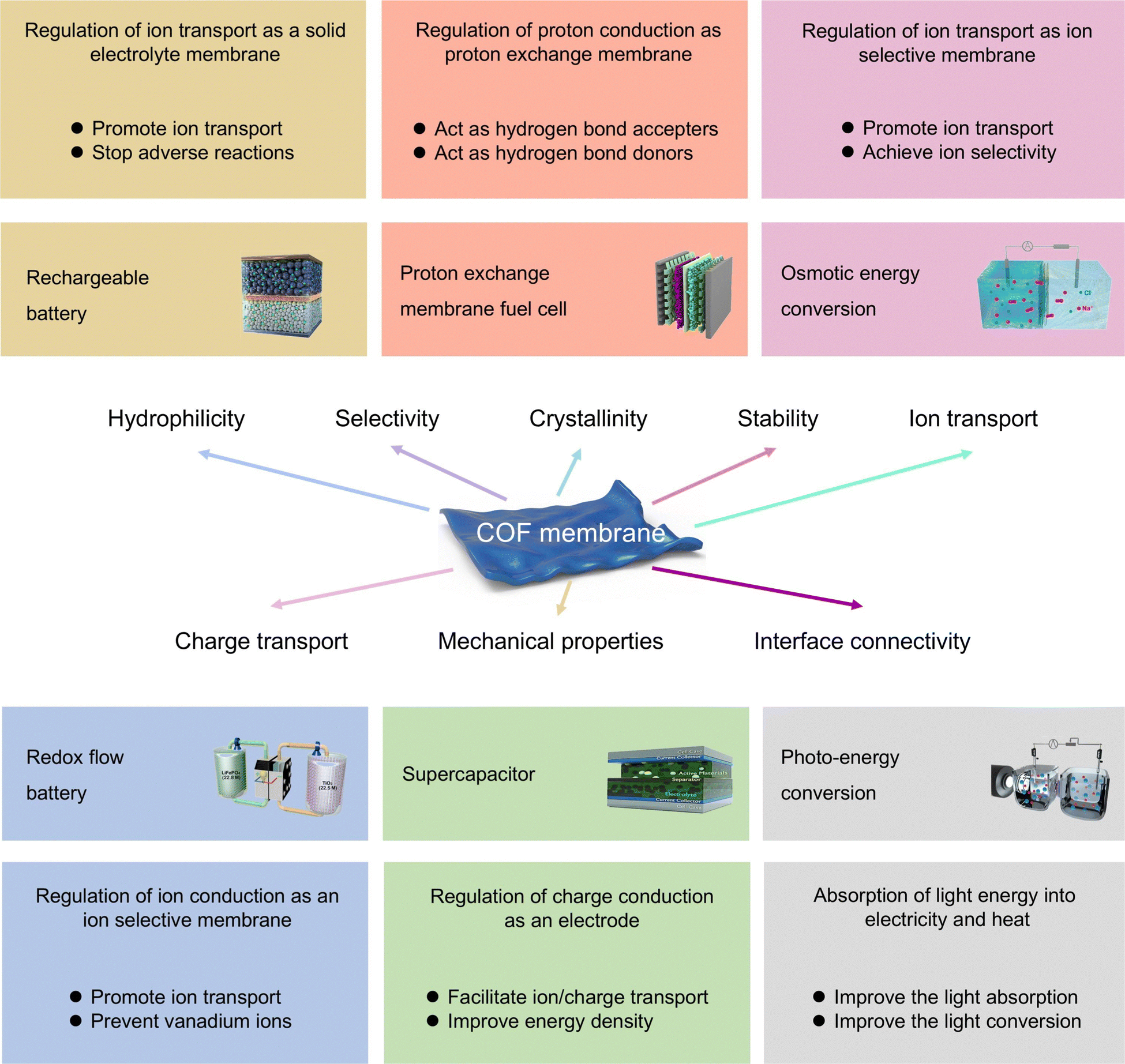 | ||
| Fig. 21 Schematic summary of the role and function of COF membranes in energy storage and conversion applications. | ||
5.1 Fuel cell
To overcome the challenging environmental and energy issues, various advanced energy storage and conversion devices are being exploited, among which proton exchange membrane fuel cells (PEMFCs) are recognized as remarkably promising choices because of their excellent properties for high energy density, mild operating conditions, and low pollutant emissions.302 The PEMs in PEMFCs can both conduct protons and act as an electron insulator and reactant barrier for cathode/anode. In this regard, proton/anion conducting COFs can be constructed by modifying the frameworks with proton donor groups (e.g., carboxylic acid, phenolic hydroxyl, sulfonic acid, and quaternary ammonium) or loading proton carriers (e.g., H3PO4, phytic acid, imidazole, and ionic liquid) in their nanopores.27,51 For example, Jiang and coworkers presented a modulation strategy with solvent and diffusion as co-mediators for the preparation of highly crystalline NUS-9 nanosheets, which can be fabricated by vacuum-assisted self-assembly into robust and defect-free COF membranes (Fig. 22a and b).150 The rigid ionic nanochannels of NUS-9 allow for superior water retention and proton conduction dominated by the Grotthuss mechanism, resulting in weak humidity-dependent fuel cell performance and proton conductivity over a wide humidity range. Moreover, the swelling ratio and water absorption of the IPC-COF membrane remained virtually unchanged even when the temperature was raised from 25 °C to 100 °C, further confirming their exceptional framework rigidity, structural integrity, and mechanical stability. Noticeably, the strategy of employing COF membranes with rigid and crystalline nanochannels to decrease the humidity dependence of the proton conduction process may be another research direction for designing the next generation of PEMs. More importantly, the IPC-COF membrane presented higher proton conductivity and fuel cell performance compared to Nafion 212 membranes due to the continuous and rigid proton conduction nanochannels inside the IPC-COF membranes (Fig. 22c and d). Further, to obtain COF membranes with higher crystallinity, higher porosity, and self-support, Banerjee and coworkers prepared three COF membranes (TpAzo, TpBpy, and TpBD(Me)2) for PEMFCs by an amino p-toluene sulfonic acid salt mediated (PTSA·H2O), slow-crystallization approach.303 Notably, the introduction of PTSA has two crucial roles: (i) increasing the crystallinity and porosity of COF membranes as an auxiliary reagent; (ii) enhancing the proton conduction properties of COF membranes. Importantly, although the degree of proton donor impregnation (8–12 wt%) was low compared to other reported materials, the COF membranes formed by slow-heating at moderate temperatures (50–90 °C) for three to four days show superior proton conductivities (PTSA@TpAzo, 7.8 × 10⁻² S cm−1 at 80 °C and 95% RH). Moreover, the formed COF membrane has excellent prevention of reactive gas crossover and exhibits a maximum current density of 90 mA cm−2 and a maximum power output of 24 mW cm−2. | ||
| Fig. 22 COF membranes as proton conducting membranes for FCs. (a) Schematic illustration of pore characterizations, cross-sectional properties, morphological stability, and fuel cell performance of IPC-COF membranes; (b) SEM images of IPC-COF membranes; (c) and (d) the comparison of Nafion 212 and IPC-COF membrane in proton conductivity and fuel cell performance. (Reproduced with permission from ref. 150. Copyright 2020, Wiley-VCH) (e) Schematic representation of the synthesis process of 3D SCOF membranes by imine condensation and interfacial polymerization; (f) SEM images of 3D SCOF membranes; (g) and (h) the proton conductivity of SCOF membranes under 100% RH and the comparison in proton conductivity of SCOF membrane with other membranes. (Reproduced with permission from ref. 259. Copyright 2023, Springer Nature). | ||
By rationally designing the density and type of framework groups of COFs, Jiang and coworkers reported three COF membranes with a tunable density of quaternary ammonium groups as efficient anion conductors.200 Quaternary ammonium groups are integrated into the framework of COFs through flexible alkyl side chains, endowing the resulting COF nanochannels abundant in cationic groups. Notably, the presence of flexible side chains greatly alleviated the steric hindrance and electrostatic repulsion generated by the quaternary ammonium cationic groups, thus guaranteeing a tight stacking inside the COF membranes. Therefore, the formed COF membranes present excellent dimensional stability and exceptional anionic conductivity (300 mS cm−1 at 80 °C and 100% RH). Additionally, as we mentioned above, with the geometry of the building units and the nature of covalent bonding connections, 2D or 3D COF structures can be flexibly constructed. Interestingly, some 3D COFs exhibit dynamic changes in spatial configuration when stimulated by different external environments, which provides novel ideas for the design of high-performance proton conductors. In this regard, Wu and coworkers used interfacial polymerization to fabricate 3D COF (COF-300) based proton exchange membranes with interconnected nanochannels, no defects, and high stability.304 With the spatial contraction and expansion of COF-300 in aqueous (3.3 Å) and ethanol solutions (9.6 Å), etidronic acid was locked in its nanochannels as proton carriers. Therefore, the etidronic acid@COF-300 membrane exhibited superior proton conductivity at 100% relative humidities and different temperatures (0.236 S cm−1 at 30 °C and 0.65 S cm−1). Similarly, Jiang and coworkers presented a 3D COF membrane (SCOF) using a dual-acid-mediated (acetic acid and octanoic acid) interfacial polymerization strategy for efficient proton conduction (Fig. 22e).259 Notably, the prepared SCOF membrane was intact, flexible, defect-free, and mechanically robust (Fig. 22f). In this process, the aldehyde-acid complex and amine-acid complex diffuse in opposite directions and to start the reaction to form microcrystals and connect to form membrane. Briefly, the monomer–acid complex interactions can play a key role in modulating the monomer diffusivity, which is essential for the formation of stable and defect-free COF membranes. Moreover, the proton conductivity of SCOF membrane can reach 0.843 S cm−1 at 90 °C and 100% RH, which shows great potential compared to other PEMs (Fig. 22g and h).
From another point of view, the performance of fuel cell is also affected by the resistance to oxygen transport in the catalyst layer. In this regard, combining novel COFs with Nafion could be an effective solution to this problem. Therefore, Wang and coworkers prepared a “breathable” proton conductor by blending α-aminoketone-linked COF ionomers (Am-COF-3-SO3H) with Nafion (Fig. 23a).305 In brief, the α-aminoketone-linked Am-COFs were converted from the imine-linked TAPB-BPDA-COF by a linker exchange method. As we mentioned in Section 2, the linker exchange method can effectively separate the crystallization process and the formation of irreversible bonds of COFs, allowing the construction of COFs that cannot be constructed in a single step. Therefore, Am-COFs exhibit excellent chemical/thermal stability due to the irreversible a-aminoketone bonds. To improve the dispersion of Am-COF and reduce the phase separation from other components, sodium propanesulfonic acid was grafted on the pore wall of Am-COF to obtain Am-COF-SO3H. Compared to Nafion, the Am-COF-SO3H exhibited excellent water adsorption and water retention, which was attributed to the high flexibility of the framework at high temperatures, favoring the creation of numerous hydrogen bonds with guest water molecules (Fig. 23b). With these superior stability and water retention as well as abundant hydrogen bonding network, the peak and power densities of Am-COF-SO3H/Nafion composite membrane in a hydroxide fuel cell were 1.01 and 1.87 times higher than Nafion membranes, respectively (Fig. 23c and d). This breakthrough highlights the potential of COF composite membranes to address the fundamental challenge of fuel cells to enhance the fuel cell performance at medium operating temperatures.
 | ||
| Fig. 23 COF membranes as proton conducting membranes for FCs. (a) Synthetic route of Am-COF-3-SO3H; (b) schematic diagram of simulated proton conduction in COF/Nafion composite structure; (c) water content of around per –SO3− in pure Nafion and Am-COF-3-SO3H; (d) polarization and power density plots of Nafion and Am-COF-3-SO3H in H2-O2 fuel cells. (Reproduced with permission from ref. 305. Copyright 2024, AAAS, Science) (e) Schematic diagram of the aminopropyl quaternary ammonium-functionalized COFs; (f) schematic diagram of the microstructure and interactions at the DPBI/DCOF; (g) relationship between hydroxide conductivity and DCOF content in PBI substrates; (h) polarization and power density plots of DCOF/DPBI-20% at 70 °C. (Reproduced with permission from ref. 306. Copyright 2025, Wiley-VCH). | ||
For COF microcrystalline powders, hot pressing may lead to unavoidable gaps between COF nanoparticles thus leading to excessive ion transport resistance.307 To optimize the microstructure of ionic channel and strike a balance between high ionic conductivity and dimensional stability, Wu and coworkers prepared an anion exchange membrane by doping a high-crystallinity COF with aminopropyl quaternary ammonium (QA) cationic side chain (DCOF) into polybenzimidazole (PBI) matrix (Fig. 23e).306 Notably, the lower hydrophilicity of aminopropyl spacer compared to the reported ether-QA side chains resulted in excellent hydroxyl conductivity (172.5 mS cm−1 at 80 °C) and low swelling ratio (5.3%) of DCOF composite membranes. Moreover, molecular dynamics simulations showed that the strong interfacial interaction between PBI and DCOF enhanced the PBI-DCOF compatibility, resulting in the doping of DCOF in PBI up to 20 wt% (Fig. 23f). Therefore, the PBI/DCOF composite membrane could achieve maximum power density of 323 mW cm−2 at 70 °C in hydrogen–oxygen fuel cells, which exceeds most of the reported COF composite membrane (Fig. 23g and h).
Indeed, COF materials have been intensively and extensively studied in the field of proton conduction, and several pristine and post-modified COF materials exhibited extraordinary proton conductivity and far exceeded conventional Nafion materials (Table 3). In particular, the editable framework structure of COF membranes offers numerous possibilities for building different functions. However, it is worth noting that how to achieve extraordinary durability of COF membranes in PEMFCs is an issue that requires special attention. Overall, COF materials, especially COF-based membrane materials, have tremendous development potential and improvement space for fuel cell applications.
| COF-based membrane | Conductivity (mS cm−1) | IEC (mmol g−1) | Stress (MPa) | Working condition | Ref. |
|---|---|---|---|---|---|
| IL-COF-SO3H@SNF-35 | 205 | 1.93 | 29 | 80 °C and 100% RH | 308 |
| TB-COF@LCNFs-12 | 348 | 2.85 | 72.98 | 80 °C and 100% RH | 309 |
| CON-2(SO3H)@CS-3 | 353 | 2.81 | 95 | 80 °C and 100% RH | 310 |
| SNWs/LCNF@TP-COF-25 | 395 | 2.72 | 109.8 | 80 °C and 100% RH | 311 |
| TpBd–SO3H(2) | 1389 | 5.4 | — | 90 °C and 100% RH | 151 |
| SCOF | 540 | — | — | 80 °C and 100% RH | 17 |
| Nafion/Z-COF-10 | 220 | 0.85 | 26 | 80 °C and 100% RH | 312 |
| IL-COF/GPPO-5 | 89.98 | 2.42 | 35 | 80 °C and 100% RH | 313 |
| TJU-1 | 187 | 2.99 | 30.4 | 80 °C and 100% RH | 307 |
| 10%ZUT-COF-SO3H@Nafion | 133.8 | — | — | 80 °C and 100% RH | 314 |
| Nafion/P-COF-4 | 141 | 1.42 | 49.9 | 25 °C and 100% RH | 315 |
| SPC-COF-NS | 364.1 | 3.42 | 24.3 | 80 °C and 98% RH | 316 |
| Z-TpPa | 180 | — | — | 80 °C and 98% RH | 317 |
| COF-SDQA | 329.4 | 2.73 | 27 | 80 °C and 100% RH | 200 |
| 40%-COF-OPBI | 177.7 | — | 12.1 | 160 °C | 318 |
| PTSA@TpAzo | 78 | — | — | 80 °C and 95% RH | 303 |
| SPEEK/HPW@COF-15 | 6.2 | 1.75 | 75 | 65 °C and 40% RH | 319 |
| Nafion/H3PO4@S1-15 | 60.4 | — | — | 80 °C and 51% RH | 320 |
| im@PI-2/PPO-5 | 147 | 2.76 | 18.8 | 80 °C and 100% RH | 321 |
| TpPa–SO3H/DGO-15% | 916.4 | 2.45 | 87.8 | 80 °C and 100% RH | 322 |
| DNA@iCOF-3 | 494.7 | 3.55 | 50 | 80 °C and 98% RH | 323 |
| TpBd-C3-SO3H | 889 | — | 90 | 90 °C and 100% RH | 199 |
| SPEEK/TpBd-C3-SO3H-6 | 540.4 | 2.62 | 120.41 | 80 °C and 100% RH | 262 |
| TpBD–(SO3H)2 | 660 | 4.6 | — | 90 °C and 100% RH | 258 |
| 3D SCOF | 843 | 4.1 | — | 90 °C and 100% RH | 259 |
| SPEEK/TpPa–SO3-5 | 346 | 2.34 | 74.5 | 80 °C and 100% RH | 324 |
5.2 Rechargeable battery
Rechargeable batteries with long cycle life, high energy density, and superior safety/reliability are urgently required to realize low carbon emissions and sustainable development of society. At the material level, a stable electrode–electrolyte interface is undoubtedly the fundamental breakthrough in battery performance, and a source of motivation to promote the replacement and upgrading of rechargeable batteries.325–330 In this regard, the characteristics of COF-based membranes such as porosity, structure, roughness, wettability, thickness, and security can significantly influence the ion transport efficiency, long-term cyclability, and internal resistance of rechargeable batteries. Therefore, this section focuses on the potential applications of solid-state electrolytes based on COF-based membranes in representative lithium metal batteries (LMBs), lithium–sulfur batteries (LSBs), zinc-ion batteries (ZIBs), and sodium–sulfur batteries (SSBs). Notably, in addition to being employed as a solid electrolyte, the COF membrane can also be used as a protective membrane for metal anodes to promote uniform ion deposition, resulting in higher and more stable electrochemical performance.260,299,300As the most extensively employed member of the rechargeable battery, LMBs have attracted persistent and extensive research interest as electrochemical energy storage devices with low self-discharge, high energy density, minimal memory effect, and stable recyclability. Separators play a crucial role in regulating ion transport behavior and maintaining short-circuit safety. However, the non-uniform deposition of Li+ in LMBs typically results in the creation of lithium dendrites, which can cause severe puncture of the separator and short circuits.331–333 In this case, COF-based membranes with well-organized distribution and continuous nanochannels offer an emerging platform for uniform Li+ transport and deposition.334,335 Meanwhile, the trade-off between ionic mobility number and mechanical strength has remained in solid-state separators. To explore solid-state ionic conductors with equilibrium properties, Manthiram and coworkers presented an electrolyte-mediated single lithium-ion conducting COF solid-state conductor (Fig. 24a).336 Briefly, the presence of lithium bis(trifluoromethanesulfonyl)imide (LiTFSI) can initiate the copolymerization of dimethylacrylamide (DMA) to form a polymer electrolyte with high ductility (Fig. 24b). Taking advantage of this property, the DMA@LiTFSI solution was encapsulated into the nanopores of LiCOFs for in situ polymerization. Notably, the presence of functional groups of flexible DMA chains in COF nanochannels can release Li+ from the rigid framework of COFs and decouple LiTFSI, which dramatically accelerates the ordered movement of Li+. Therefore, the formed DMA@LiTFSI-mediated COF (DLC) electrolyte exhibited excellent ionic conductivity (1.7 × 10⁻⁴ S cm−1), high t+ (0.85), excellent long-term voltage stability, and superior mechanical stability (22 MPa) (Fig. 24c). Notably, Li+ can diffuse predominantly along the pore walls of Li-COF, the larger pore volume is detrimental to ion conduction and dilutes the overall charge carrier concentration (Fig. 24d). In the DLC channels, the functional groups of DMA can release Li+ from the rigid COF backbone, thus facilitating Li+ conduction. Therefore, the DLC electrolyte exhibited a stable Li plating/stripping in a Li/Li symmetric cell for 450 h (Fig. 24e). Importantly, this special copolymerization strategy demonstrated the tremendous potential of COF composite membranes in terms of regulating the uniform transport and deposition of Li+ in solid-state electrolytes. Further, it is necessary to inhibit the uncontrolled deposition of Li+ by promoting Li+ migration and the irreversible depletion of the cathode by suppressing polysulfide shuttling to achieve the practical application of LSBs.337 Loh and coworkers reported a fluorinated COF membrane (4F-COF) with high selectivity and durability for LSBs (Fig. 24f).338 Briefly, the selective nanofluidic channels were created by integrating fluorine functional groups into the nanochannels of COFs. Therefore, the formed 4F-COF membranes have high density and ordered negatively charged ion channels that can prevent polysulfide migration, as well as Li+ transport properties (Fig. 24g and h). With these properties, LSBs assembled with 4F-COF have a Li metal endurance of more than 2000 h at 1 mA cm−2, a capacity decay of 0.018% per cycle for 1000 cycles at 2C, and rate performance of 568 mA h g−1 at 10C (Fig. 24i). In particular, a reversible capacity of 5.35 mA h cm−2 and a capacity retention of 70.4% (over 200 cycles) can be obtained in a high sulfur-loaded cathode and poor electrolyte. The results highlight the superiority of COF functionalized separators for practical LSB applications.
 | ||
| Fig. 24 COF membranes as solid electrolyte membranes for RBs. (a) Synthesis process of LiCOF; (b) synthesis process of DMA/LiTFSI; (c) digital photos of MA@LiTFSI-mediated COF (DLC) electrolyte; (d) schematic of Li+ transport in conventional SPE, LiCOF, and DLC; (e) cycling capacity of Li/LiCOF/Li and Li/DLC/Li symmetric cells. (Reproduced with permission from ref. 336. Copyright 2022, Wiley-VCH) (f) The topology structures of Df-THzOPr-COF and Df-4F-THzOPr-COF; (g) contact angles between electrolyte and PP and 4F-COF/PP; (h) Li+ transference number and zeta potential of different separators; (i) cycle stability of Li/4F-COF/Li, Li/Df-COF/Li, and Li/PP/Li symmetric cells at 1 mA cm−2. (Reproduced with permission from ref. 338. Copyright 2023, American Chemical Society). | ||
In general, COFs are built by dynamic covalent bonding (e.g., boronate and imine) and can be realized as extended ordered structures by error correction. It should be mentioned that the inherent reversibility of these bonds unavoidably results in their weak chemical stability, thus posing a great limitation to their practical applications, especially in membrane technologies.339 As we mentioned above, the construction of COFs employing irreversible bonds such as pyridinium, phenazine, dioxin, and CC stands as a critical strategy for pursuing high chemical stability. To obtain crystalline and oriented COF membranes, Feng and coworkers reported two novel vinylene-linked cationic COF membranes (V-C2DP-1) with robust frameworks and oriented 1D nanochannels as anion-selective electrode coating for ZIBs.340 Notably, the formed V-C2DP membranes exhibited superior TFSI− selective transportation in facilitating the working voltage, intercalation phase, and reversibility of graphite cathodes in ZIBs due to their oriented 1D channels, well-defined cationic sites, and highly stable frameworks. Therefore, the resulting ZIBs displayed superior long-term cycling life (95% capacity retention after 1000 cycles) and higher specific capacity (124 mA h g−1). This strategy also provided a promising platform for the development of novel COF membranes with oriented 1D channels and highly stable frameworks.
Further, from the perspective of SSBs, the design of an ideal SSB separator should consider the following aspects: (i) uniform pore structure and high selective Na+ transport capacity to enhance the charging/discharging rate of batteries; (ii) continuous dense structure to block sodium polysulfides and inhibit polysulfide shuttle effect; (iii) efficient conversion of an inert layer of polysulfide on the separator surface to inhibit cell polarization. Therefore, from these issues, Lu and coworkers proposed a design strategy to mimic the function and structure of human cerebral blood vessels to construct bilayer-structured COF composite membranes (HB/CNT@COF) that integrate three components [COF-300, carbon nanotubes (CNTs), and hydroxynaphthol blue (HB)] for SSBs.341 To maximize the effect of COFs, COF-300 with high chemical stability and angstrom-sized pores was selected as the anchoring matrix, which could alleviate the clogging of nanopores by guest molecules and realize the penetration of CNTs due to its special 3D spatial structure. In this process, the conjugated HB molecules and CNTs readily bind to COF-300 by π–π stacking interactions, resulting in the fabrication of HB/CNT@COF composite membranes during interfacial polymerization. Therefore, the SSBs assembled with HB/CNT@COF composite membranes exhibited high capacity (733.4 mA h g−1) and excellent operational stability at 4C. Notably, the host–guest self-assembly strategy extends the application scenario of COF membranes to high-performance SSBs, providing a new perspective on the design of COF-based electrolytes.
As we mentioned above, the ordered open channels and tunable structure of COFs provide an ideal platform to study the ion transport behavior inside the atomically precise frameworks. Noteworthy, COFs have the disadvantages of irregular powder morphology, insolubility in common solvents, and non-melting at high temperatures during processing. Given these challenges, Zhang and coworkers prepared a COF membrane-based electrolyte for LMBs with excellent mechanical/thermal/electrochemical stability by incorporating flexible organic lithiophilic segments into the rigid framework of COF structure via a side-chain engineering strategy (Fig. 25a).342 In brief, a bottom-up self-assembly method was employed to integrate flexible polyethylene glycol (PEG) molecules into the framework of COFs, which facilitates the rapid transport of Li+ through their segmented motion in the rigid 2D COF structure. Expandable, flexible, and tough PEG2-COMs were subsequently obtained by electrostatic spinning and vacuum drying (Fig. 25b). In particular, the PEG2-COMs with PEG chains can provide uniformly dispersed lithophilic sites, which facilitates the uniform deposition of Li+ and improves the stability of the interface between the electrolyte and Li anode. Therefore, the plating/stripping curves of Li/Li symmetric batteries using PEG-COMs showed a stable voltage profile with low hysteresis, suggesting the formation of a stable interface at Li anode (Fig. 25c). That is, this strategy provides a general method for building scalable COF membrane-based electrolytes, broadening the practical application of COF membranes in solid-state LMBs.
 | ||
| Fig. 25 COF membranes as solid electrolyte membranes for RBs. (a) Schematic diagram of the preparation process of PEGx-COMs; (b) SEM images of PEG2-COMs and PEG2-COMs-HT; (c) Li plating/stripping curves for symmetric Li-ion batteries using PEGMEs, PEG1-COMEs, and PEG2-COMEs. (Reproduced with permission from ref. 342. Copyright 2024, Wiley-VCH) (d) Schematic scheme of OH−@P+-X-COFs; (e) schematic diagram of the preparation process of vapor-assisted COF film; (f) galvanostatic charge/discharge tests of OH−@P+-X-COF film/hydrogel-based zinc–air batteries. (Reproduced with permission from ref. 343. Copyright 2024, Wiley-VCH). | ||
In addition, to fully exploit the application of COF membranes in rechargeable batteries, Kim and coworkers synthesized a OH−@P+-X-COF membrane electrolyte for zinc–air batteries with superior hydroxide conductivity using p-phenylenediamine and quaternized phosphonium monomers with aldehyde functional groups monomers by a vapor-assisted method (Fig. 25d and e).343 Notably, the vapor-assisted method can effectively reduce the grain boundaries on both mesoscopic and macroscopic scales, thereby minimizing the contact resistance in the COF membranes. Therefore, the free-standing COF membranes can be synthesized when the optimal ratio of phosphine to phosphonium is 6![[thin space (1/6-em)]](https://www.rsc.org/images/entities/char_2009.gif) :4, with OH− conductivity up to 126.3 mS cm−1 at 80 °C. Due to the high water retention capacity, OH−@P+-60-COF hydrogel electrolyte exhibited a substantially stable cycle life of 2300 min in air (Fig. 25f). Compared to pure PVA hydrogel-based electrolyte or other solid-state electrolytes, OH−@P+-60-COF film/hydrogel electrolyte can offer superior battery performance in terms of discharge capacity, power density, and cycle life.
:4, with OH− conductivity up to 126.3 mS cm−1 at 80 °C. Due to the high water retention capacity, OH−@P+-60-COF hydrogel electrolyte exhibited a substantially stable cycle life of 2300 min in air (Fig. 25f). Compared to pure PVA hydrogel-based electrolyte or other solid-state electrolytes, OH−@P+-60-COF film/hydrogel electrolyte can offer superior battery performance in terms of discharge capacity, power density, and cycle life.
The critical parameters used to evaluate COF membranes for rechargeable battery applications are summarized in Table 4. As we mentioned above, COF-based membranes with ordered pores and regular channels are prominently advanced in regulating ion transport behaviors and have broad application prospects in rechargeable batteries. Notably, COF membranes in rechargeable batteries are still significantly affected by the preparation method, crystallinity, stability, and mechanical strength. For example, in situ interfacial polymerization on the substrate surface provides direct access to oriented and ordered COF membranes. These COF membranes are thinner and have lower internal resistance but reduced mechanical strength. Various COF membranes are complicated to prepare and require harsh organic solvents. Therefore, simplification of COF membrane synthesis methods for rechargeable batteries to achieve economic viability for further industrial applications.
| COF-based membranes | Battery type | Fabrication method | Initial capacity (mA h g−1) | Cycling performance (mA h g−1) (cycles, rate) | Ref. |
|---|---|---|---|---|---|
| Li-CON@GN | Li | Filtration | 982/1C | 645 (600, 1C) | 344 |
| DMTA-COF/CNT | Casting | 1068/1C | 621 (500, 1C) | 345 | |
| TpPa–SO3Li | Filtration | 822.9/0.2C | 641.8 (100, 0.2C) | 193 | |
| SCOF-Celgard | Casting | 925/0.5C | 750 (120, 0.5C) | 346 | |
| SCOF-2 | Casting | 795/1C | 497 (800, 1C) | 347 | |
| PyBBT-COF | Filtration | 1249/0.2C | 905 (100, 0.2C) | 348 | |
| Py-DPP-COF@CNT | Casting | 1016/1C | 584 (1000, 1C) | 349 | |
| CB-COF | Casting | 942/1C | 569 (1000, 1C) | 350 | |
| COF-SO3H@rGO | Casting | 1163.4/0.2C | 523 (1000, 2C) | 351 | |
| TpPa–SO3H@PP | In situ IP | 863.97/1C | 645.62 (500, 1C) | 352 | |
| QTB-SA/COF/PP | Filtration and casting | 900/1C | 494 (500, 1C) | 353 | |
| PMCB-COF | Casting | 926/1C | 625 (500, 1C) | 354 | |
| COF-LiSTFSI | Filtration | 884.5/1C | 454 (1000, 1C) | 355 | |
| 4F-COF/PP | Casting | 1037/0.2C | 873.1 (100, 0.2C) | 338 | |
| NaOOC-COF | Na | Casting | 149/0.2C | 130 (600, 0.2C) | 356 |
| sp2c-COF | Casting | 160/1C | 129.6 (2450, 1C) | 357 | |
| HB55.2@COF | In situ IP | 933/0.2C | 733.4 (400, 4C) | 341 | |
| BSCPE | Casting | 115.7/0.1C | 100.4 (200, 0.1C) | 140 | |
| Azo-TbTh | In situ IP | 820/1C | 524 (1000, 1C) | 358 | |
| TpPa–SO3H | Zn | In situ IP | 190/0.2C | 179 (1000, 0.2C) | 254 |
| TCOF-S-Gel | Casting | 248/1C | 230 (1400, 2C) | 153 | |
| Tp-Bpy | In situ IP | 195.4/0.5C | 145.6 (400, 0.5C) | 359 | |
| COF-S-F | Casting | 235.3/1.2C | 206.8 (800, 1.2C) | 360 |
5.3 Redox flow battery
As an efficient and unique large-scale energy storage system, redox flow batteries (RFBs) have been employed in combination with wind and solar energy for peak shaving and valley filling on the grid, thus overcoming the unsustainability and instability of these renewable energy sources. In particular, the selectivity and proton conductivity of ion conductive membranes also have a decisive influence on the coulombic efficiency (CE) and voltage efficiency (VE) of RFBs. In this regard, the tailorable nanochannels and nanoscale pores of COF-based membranes give them tremendous potential for overcoming the trade-off between membrane selectivity and ionic conductivity.361,362 To achieve COF membranes with long-term stability and exceptional structural integrity under practical RFB operating conditions, Xu and coworkers proposed a strategy based on mechanochemistry and macromolecular suturing to prepare an azo-functionalized COF membrane with high stability and proton conductivity for RFBs (Fig. 26a).259 Briefly, the SPEEK macromolecular chains were employed as an adhesive between COF materials, stitching the inevitable structural defects within the membrane during the phase inversion process (Fig. 26b). In this process, the functional chains of sulfonate groups of SPEEK can fill large-sized defects, enhance the interactions between COF clusters, and offer alternative active sites for proton transportation across membranes (Fig. 26c). Notably, the optimized SPEEK@TpAzo membrane presented a high VE of 79.06% at 40 mA cm−2 and maintained nearly 100% of its discharged capacity even after 100 cycles at 80 mA cm−2, which is better than pure TpAzo membrane (Fig. 26d). Importantly, the strategy of using macromolecular stitching to fabricate freestanding COF membranes in a facile way promotes the development of COF membranes for RFBs. Similarly, to address the trade-off between the selectivity and conductivity of SPEEK membranes in RFBs, Meng and coworkers utilized the Donnan effect between COF-immobilized imidazolium-based ionic liquid and SPEEK polymeric materials to construct SPEEK/IL@TpPa–SO3H composite membrane with high ion selectivity for RFBs.363 Notably, the vanadium resistance of the SPEEK membrane was further enhanced by the Donnan effect of repulsion of the sane charge and attraction of the opposite charge between the imidazole and Vn+. To reduce the leakage of ionic liquid in the SPEEK matrix, porous COFs (TpPa–SO3H) with sulfonic acid functional groups were employed to immobilize the ionic liquid. With the synergistic effect of these strategies, the SPEEK/IL-5@TpPa–SO3H-3 composite membrane displayed higher CE (98.43%) and EE (91.7%) than the SPEEK/IL-5 and Nafion 115 membranes in the assembled RFBs at the current density range of 40–120 mA cm−2. | ||
| Fig. 26 COF membranes as ion conducting membranes for RFBs. (a) Schematic illustration of the preparation process of SPEEK@TpAzo membrane; (b) SEM images of TpAzo and SPEEK@TpAzo-4 membranes; (c) schematic diagram of proton conduction in SPEEK@TpAzo-4 membrane; (d) cycling efficiencies of TpAzo and SPEEK@TpAzo membranes; (reproduced with permission from ref. 364. Copyright 2018, Elsevier) (e) schematic illustration of the preparation process of self-standing TpPa–SO3H/SPEEK composite membranes; (f) digital photos and SEM images of TpPa–SO3H/SPEEK-1% composite membranes; (g) cycling efficiencies of TpPa–SO3H/SPEEK composite membranes at 80 mA cm−2; (reproduced with permission from ref. 365. Copyright 2023, Wiley-VCH). | ||
Following a similar research path, to prepare self-supported COF membranes with high permeation selectivity and crystallinity for RFBs, Xu and coworkers fabricated self-supporting COF membranes with excellent flexibility and high crystallinity through a macromolecule-mediated strategy and demonstrated enhanced performance in RFBs (Fig. 26e).365 The suitable nanochannels and abundant acid group frameworks of TpPa–SO3H enable the formed membranes with effective rejection of active substances and superior proton conduction. Noticeably, the introduction of SPEEK macromolecular chains as a long-range ordered template through a macromolecule-mediated strategy led to the controlled crystallization of TpPa–SO3H COFs. Briefly, the –SO3H groups of SPEEK can interact with the amine precursor of TpPa–SO3H and act as growth points to promote the directed crystallization of self-supporting COF membranes. Therefore, the TpPa–SO3H/SPEEK-1% prepared utilizing this method is flexible, continuous, and defect-free (Fig. 26f). Further, the RFBs equipped with self-standing sulfonated COF membranes exhibited superior stability during 300 cycles (Fig. 26g). Likewise, inspired by the precise pore size adjustability and superior compatibility of COFs, Yan and coworkers utilized Schiff base-type COF (SNW-1) to improve the proton conductivity and selective permeability of polybenzimidazole (PBI) substrates in RFBs.366 Briefly, SNW-1 with appropriate pore size (0.48 nm) for accurate screening of vanadium ions (>0.6 nm) and hydrated protons (<0.24 nm). Meanwhile, SNW-1 is also compatible with PBI substrates. Consequently, thanks to the nitrogen-rich surface (up to 40 wt%) and micropores of SNW-1, the formed PBI/SNW composite membranes presented superior proton conductivity, excellent vanadium permeation resistance, high VE (94.8%) and CE (98.7%).
In addition to these COF composite membranes blended with polymers, self-standing COF membranes with continuous ion-transport channels may have greater potential for improving the efficiency and power of RFBs. In particular, the homogeneous structure in pure COF membranes avoids the problem of incompatibility of different materials. In this regard, several issues of self-standing COF membranes require special attention: (i) low mechanical property; (ii) low chemical property (imine linkages); (iii) relative low selectivity for vanadium ions (>8 Å). Therefore, to address these problems with self-standing COF membranes, Wang and coworkers prepared an amine-linked self-standing covalent-organic polymer (COP) membrane (TAPT-CC) with 4.5 to 6.4 Å sub-nanometer pores for RFBs. Notably, amine linkages (the irreversible secondary amine linkages and triazine core) have higher chemical stability than imine linkages, allowing them to withstand harsher chemical environments. TAPT-CC membrane was prepared by in situ polymerization between 2,4,6-tris(4-aminophenyl)-s-triazine (TAPT) and cyanuric chloride (CC). Notably, the synthesized TAPT-CC membrane exhibited superior mechanical properties (30 MPa) and vanadium ion selectivity. The selectivity of TAPT-CC membrane is mainly derived from the “ion sieve” effect produced by the ultra-micropores structure. Specifically, the distribution of micropores within the TAPT-CC membrane ranged from 4.5 to 6.4 Å, whereas the dynamics diameters of hydrated hydrogen ions and hydrated vanadium ions were 3 Å and 8 Å, respectively. That is, the ion selectivity was achieved by the size confinement of COP membrane, which was also discussed in Section 4.4. Moreover, the persistent pore structure and hydrogen bonding network in TAPT-CC membranes enabled fast proton transport. Thanks to excellent mechanical strength, superior ion selectivity, and continuous hydrogen bonding network, TAPT-CC membrane achieved remarkable efficiency (energy efficiency of over 80% at the current density of 200 mA cm−2) and durability (over 1000 cycles) in RFBs.
Ideal RFB separators need to have excellent proton conductivity, superior ionic selectivity, and good electrochemical stability. As we mentioned in Section 4, COF membranes can achieve excellent proton conductivity, selectivity, and stability through bottom-up design and post-synthetic modification strategies. Therefore, COF membranes exhibit tremendous potential in the application of RFB separators. In this process, polymer/COF composite membranes have been extensively studied due to their simplicity and scalability. For pure COF membranes, excellent mechanical/chemical stability and optimized ionic selectivity are the three main elements for their application in RFBs. That is, future research on pure COF membranes should focus on these three areas.
5.4 Supercapacitor
As an energy storage technology, supercapacitors (SCs) have become a hotspot of attention in academia and industry for their excellent performance such as high-power density, maintenance-free, and long-term operation. In terms of power density and energy density, SCs are intermediate between batteries and dielectric capacitors, with higher energy density than the latter and higher power density than the former.367–369 Moreover, SCs are characterized by higher safety, environmental friendliness, higher reliability, rapid charge, and maintenance-free operation. In general, SCs are categorized into pseudo-capacitive and electrochemical double-layer capacitors based on two energy storage mechanisms.370 Electrode-active materials are typically modified to enhance the overall performance of SCs by integrating two energy storage mechanisms to enhance the conductivity, specific surface area, and modification of redox-active groups.371 In this regard, COFs with well-defined nanochannels, inherently large surface areas, long-range ordered arrangements, and redox-active building blocks, bring new development opportunities for the materials design of SCs.372,373 Briefly, the utilization of COF materials as building blocks for SCs follows several design principles: (i) synthesizing redox-active skeletons by direct introduction or post-synthesis of functionalized reversible redox reaction units; (ii) enhancing the conductivity and processability of COFs by incorporating or in situ polymerizing conductive polymers in nanochannels; (iii) enhancing the capacitance and electrical conductivity of COFs by pyrolyzing to form porous carbon materials.Recently, the inorganic/organic material superlattice heterostructures have demonstrated tremendous potential for charge storage. For SCs, the distinctive 2D heterostructure can remarkably affect the charge modulation/distribution at the interface and utilize the cooperative effect of two tightly contacted stacked layers to improve the performance of SCs. Thus, from this research direction, Qian and coworkers assembled COF membrane with imine-bond connections (COF-A) and COF membrane with β-keto-enamine connections (COF-B) into superlattice self-supporting composite membrane electrode (MSC-ABA-COF) based on pseudo-capacitive and electrochemical double-layer capacitive energy storage mechanisms (Fig. 27a).374 The design concepts are listed below: (i) the structure of COFs connected by covalent bonds can be bent and stacked undisturbed and stacked in a long-range periodic manner, resulting in a uniform nano-superlattice, which offers excellent ionic proximity to the inner surface of the active site; (ii) the nature of the superlattice allows the COF layers to be freely combined, thus utilizing the synergistic effect of layers to enhance the electrochemical performance (Fig. 27b).375 The almost constant CV curves confirmed the good adaptability of MSC-ABA-COF device, while the unique superlattice structure of MSC-ABA-COF also exhibited excellent charge storage capability compared to the currently reported 2D alloys, graphite-like carbon, and undoped COF-based electrodes, leading to a high capacitance of MSC-ABA-COF (Fig. 27c). Moreover, the SC based on MSC-ABA-COF assembly can provide an energy density of 63.2 mW h cm−3 at 3.3 W cm−3 power density and superior long-term cycle stability (Fig. 27d). It can be said that this superlattice nature of COFs provides a new way for the design of novel electrodes in SCs.
 | ||
| Fig. 27 COF membranes as membrane-based electrodes for SCs. (a) Schematic illustration of synthesizing A-COF and B-COF films; (b) schematic diagram of the assembly of ABACOF superlattice; (c) CV curves of MSC-ABA-COF; (d) cycling stability of MSC-ABA-COF. (Reproduced with permission from ref. 374. Copyright 2022, Springer) (e) The synthesis and structure of g-C34N6-COF; (f) the optical photo of g-C34N6-COF/CNT film; (g) the preparation process of COF-MSC; (h) CV curves of COF-MSC; (i) the cycling stability of COF-MSC. (Reproduced with permission from ref. 376. Copyright 2019, Wiley-VCH). | ||
Indeed, the COF electrode membranes were typically prepared by vacuum extraction/filtration of COF powders/nanosheets. In this process, the unavoidable agglomeration and irregular stacking in the formed COF composite membranes hinder the ion/charge transfer to a certain extent and thus prevent the full structural advantages in SCs. Therefore, to develop free-standing COF membranes with long-range ordered porous structures, Zhang and coworkers prepared COFTAPB-DHPA membrane electrodes for SCs by utilizing the orientation effect of the surfactant monolayer and the confinement effect at the gas–liquid interface and improved the capacitance performance through metal coordination (Co-COFTAPB-DHPA) and space-partitioning (IL-COFTAPB-DHPA).242 In this process, the imidazole ionic liquid grafted within the COFTAPB-DHPA nanopores (IL-COFTAPB-DHPA) effectively increased the surface area and ensured the rapid transportation of ions, thus enhancing the electrochemical performance of COFTAPB-DHPA. The Co2+ anchored on the COFTAPB-DHPA backbone (Co-COFTAPB-DHPA) could offer extra pseudo-capacitance via reversible redox reactions of Co(II/III). Therefore, the formed COFTAPB-DHPA, IL-COFTAPB-DHPA, and Co-COFTAPB-DHPA composite membranes showed maximum energy density of 90.7 mW h cm−3, 139.7 mW h cm−3, and 230.4 mW h cm−3, superior volumetric capacitance of 723.2, 1157.9, and 1790.1 F cm−3 at 10 mV s−1, and outstanding CA/CV values, respectively. This impressive performance can be explained as follows: (i) COFTAPB-DHPA possess an open mesoporous structure and completely conjugated π–π electron system, which promotes rapid diffusion of ions from the interface to the internal for fast charge migration, thus realizing high charge storage capacity; (ii) the prepared COFTAPB-DHPA membranes have enormous advantages, such as highly long-range ordered nanochannels and ultrathin nanoscale thickness, which can ensure fast ion/charge transfer capability and superior surface charge accumulation. Importantly, this work offers some theoretical guidance for the preparation and design of large-area crystalline 2D COF membranes.
Additionally, the rational selection and design of electrode materials are critical for SCs and RBs. Currently, various active materials, including nitrides, sulfides, transition metal oxides, carbon-based substances, TiO2, and Li3VO4, have emerged as strong contenders for anode materials for batteries.377,378 However, battery anodes constructed using insertion materials present intrinsic challenges because such anodes rely on conversion reactions and alloying/dealloying. In this regard, these challenges involve inherently low electronic conductivity, slow kinetics, poor theoretical capacities, and large volume changes during lithiation/de-lithiation, leading to lower energy and power densities and impaired cycling stability.379 Therefore, to develop innovative configurations for battery anode/cathode, Qiao and coworkers proposed a molecular-level structural design strategy to construct COF membrane-based anodes (COFBTMB-TP) and cathodes (COFTAPB-BPY) for high-performance SCs.380 Interestingly, the synthesized COFBTMB-TP membrane possesses strong electronegative –CF3 groups that can regulate the electron cloud density for Li+ migration, thus ensuring the fast anodic kinetic process. The thickness-adjustable cathodic COFTAPB-BPY membrane can be matched to the capacity of anodic COF membrane. Notably, benefiting from the well-organized 1D nanochannels, 2D aromatic backbone, and easily accessible active sites of COF membranes, the formed COFBTMB-TP//COFTAPB-BPY SC exhibited high energy density (318 mW h cm−3), outstanding rate capability, remarkable cycle stability (77% capacity retention after 5000 cycles), low resistance, and slow self-discharge. That is, the challenges of SC charge storage kinetics and positive-negative capacity imbalance can be effectively addressed by utilizing reasonably designed COF membranes, which also provides a new thought for the design of electrodes for SCs.
In addition, Zhang and coworkers reported the flexible membrane electrode for micro-supercapacitor (MSC) by vacuum-filtration using fully conjugated COFs (g-C34N6-COF) with unsubstituted CC linkages prepared by Knoevenagel reaction and carbon nanotubes (CNTs) (Fig. 27e and f).376 Briefly, the fully conjugated and planar triazine core was incorporated into the 2D framework to produce the uninterrupted p-electron delocalization over 2D direction. Further, the g-C34N6-COF electrode was fabricated by mask-assisted vacuum filtration, and the COF-MSC was fabricated with a polyethylene terephthalate (PET) membrane as the substrate and LiCl/PVA as the electrolyte (Fig. 27g). Due to the abundant active sites, regular porous structure, and high specific surface area of g-C34N6-COF, the obtained COF-based MSC exhibited an equal area capacitance of 15.2 mF cm−2, an energy density of 7.3 mW h cm−3, and superior rate capability (Fig. 27h). Moreover, COF-MSC also exhibited remarkable cycling stability with 93.1% capacitance maintained after 5000 cycles (Fig. 26i). This COF-based device can provide excellent flexibility and integration capabilities for the development of wearable and portable electronic systems with unique development prospects.
5.5 Photo-energy conversion
As we mentioned above, COFs are characterized by high stability, efficient π–π conjugation, high crystallinity, large specific surface area, and charge transfer. In addition to the examples discussed above for energy storage, it is possible to construct ideal photo energy conversion materials by rational design of molecular structure and modulation of electronic structure. In this process, the crystallinity of COFs is critical to its performance. In general, the difficulty in the preparation of highly crystalline COFs may be the deviation in the ratio between dissolved copolymerized monomers due to different solubilities.381 In most situations, the monomers are only partially solubilized during interfacial polymerization or solvothermal synthesis. Therefore, it is challenging to find solvent combinations that both solubilize the monomers and keep the stoichiometry to allow the adequate polymerization of COFs. Chen and coworkers integrated two different functional groups (amino and aldehyde) in a simple pyrene molecule for the preparation of highly crystalline Py-COF membranes and as hole transport layers for perovskite solar cells (Fig. 28a and b).382 Notably, the highly crystalline and porous Py-COF membranes can be readily fabricated by the self-condensation of BFBAPy in a variety of solvents including ethanol, methanol, CHCl3, CH2Cl2, dimethylacetamide, and acetonitrile. Compared with other COF membranes, the formed Py-COF membranes exhibited better substrate adaption, lower solvent dependence, and higher transparency. This solvent adaptability of Py-COFs makes it possible to generate high-quality membranes on ITO substrate with PSS/PEDOT coating. Therefore, the solar cell with Py-COF membrane as a hole transport layer demonstrated an open-circuit-voltage of 0.76 V, a filler factor of 54.33%, a short-circuit-current of 15.38 mA cm−2, and a power conversion efficiency of 6.36% (Fig. 28c and d). Notably, the efficiency of photo-energy conversion can be improved if large-area oriented COF membranes with better interfacial quality, better-matched energy gaps, and fewer grain boundaries can be obtained. | ||
| Fig. 28 COF membrane as a conduction layer for photo-energy conversion devices. (a) Schematic illustration of the construction of 2D COF using the two-in-one strategy; (b) the synthesis process of Py-COF; (c) the device structure of perovskite solar cell; (d) schematic diagram of the current density–voltage characteristic curve using Py-COF membrane as hole transport later in a solar cell; (reproduced with permission from ref. 382. Copyright 2019, American Chemical Society) (e) synthesis routes and UV/vis-NIR absorption schematics of tBu-TPAD-BF2 and TPAD-COF-BF2; (f) the photographs of TPAD-COF-BF2 and TPAD-COF membranes and corresponding photothermal images; (g) variation of water mass with time for different membrane coverings; (h) ion concentration in seawater before and after treatment with TPAD-COF in SSG device; (reproduced with permission from ref. 194. Copyright 2022, Wiley-VCH). | ||
From another perspective, domestic wastewater purification or desalination using solar steam generation (SSG) technology is another way of converting photo-energy. In this regard, photothermal conversion materials have attracted widespread attention as critical components of SSG.383–385 Principally, promising photothermal conversion materials should possess a combination of high solar thermal conversion efficiency, broad light absorption, open porosity, high stability, low cost, and high hydrophilicity.386–388 Therefore, Wang and coworkers proposed a 1,4,5,8-tetrakis(phenylamino)anthracene-9,10-dione (TPAD)-based COF membrane with broad light-absorption properties and superhydrophilicity covering the entire UV/vis region to the near-infrared region for SSG (Fig. 28e).194 It is worth mentioning that TPAD is known as a near infrared region dye due to its intramolecular and strong dipoles hydrogen bonds between CO and NH groups. Therefore, the TPAD-linked COFs can be both broadly light absorption and hydrophilicity. To further extend the range of light absorption, a large π–π conjugated TPAD-COF-BF2 was fabricated by chelating BF2 molecules in TPAD nanopores. TPAD membranes were prepared by vacuum-filtration on hydrophilic polytetrafluoroethylene (PTFE) substrates. Further, the temperature difference between TPAD-COF membrane and TPAD-COF-BF2 membrane before and after light irradiation was 51.8 °C and 58.0 °C, respectively, which indicated that the TAPD-based COFs have superior solar-thermal energy conversion efficiency (Fig. 28f). Notably, the hydrophilic nature of TPAD-COF was transformed after BF2 doping, which was caused by the reduction of hydrophilic NH groups in the COF backbone and the incorporation of hydrophobic BF2 groups. The results showed that the TPAD-COF membrane is a high-efficiency light absorber with a water evaporation rate up to 1.42 kg m−2 h−1 and a solar energy conversion efficiency of up to 94% (Fig. 28g and h). Importantly, the hydrophilicity of COFs plays a more crucial role than the light-absorbing ability as a photothermal conversion material for SSG.
Furthermore, another way to apply COF membranes to light-energy conversion is to endow them with interesting photo-stimulation responsiveness. Zhang and coworkers demonstrated that the dithienyle-thene-based COFs can undergo a photo-induced transition without destroying the structure (UV light can turn on the conductivity, while visible light can turn off the conductivity).389 Briefly, COF-O built from the photo-responsive unit 1,2-bis(5-formyl-2-methylthien-3-yl)cyclopentene can be converted reversibly from low state to high state under UV irradiation, and also reversibly converted under visible light. Interestingly, the photo-induced ring-closing/opening reactions cannot disrupt the integrity of the COF framework, and both processes produce logarithmic carriers over time. The COF–O membrane was fabricated by interfacial polymerization in CHCl3 solution and CH3CN/H2O. During the COF membrane formation, water can maintain the insolubility of the solvent at the interface, while CH3CN can contribute to the solubility of TAPA. Notably, the reversible phenomenon of COF–O membrane can be monitored by a circuit containing light-emitting diodes. In this process, the conductivity of the COF–O membrane served as control, and after irradiation for 6 min at room temperature, the switching conversion led to an increase in its conductivity from 1 ± 0.25 × 10⁻⁷ cm−1 to 2 ± 0.23 × 10⁻⁵ cm−1, which is approximately 200-fold increase. Noteworthy, the optical properties of COF materials can be effectively modulated by inducing additional stimulus-response building units, which also provides some guidance for designing new photosensitive COFs.
As we mentioned above, the regular porous structure of COFs can be responsible for mass transport, while the π-conjugated system of COFs extending in the in-plane and stacking directions can be responsible for electron transport. Indeed, these microstructure characteristics are highly favorable for artificial photosynthesis. Therefore, inspired by the microstructures of natural leaves, Wang and coworkers synthesized a COF membrane (2N-COF) containing a triazine-imide-triazine chemical structure unit for photocatalytic carbon dioxide using interfacial polymerization.390 The light-absorbing bandgap of COFs can broaden with the increase in the number of triazine groups. Electron–hole pairs recombine easily in small bandgap sample, so increasing the number of triazine groups facilitates the separation of electron–hole pairs. Therefore, CO2 photoreduction was performed with H2O under gas-solid conditions by irradiating the COF membrane with visible light without adding any metal, sacrificial agent, or photosensitizer. After 4 h of visible light irradiation, the CO yield of 2N-COF membrane was 3.2 times higher than that of 2N-COF powders, which also demonstrated the potential of 2N-COF membrane to reduce CO2 to CO under natural sunlight. Indeed, the photocatalytic activity of 2N-COF membranes mainly stems from the presence of triazine groups, which not only offer photogenerated electrons, but also facilitate the separation of photogenerated holes and electrons. It can be said that this work opens up a new avenue for COF membranes in modeling photosynthesis in leaves, which may drive future related research.
For photoenergy conversion, the ordered structure and homogeneous pores in COFs can improve the separation and migration of photogenerated carriers. Functional groups or linkages with photo-responsive and light-absorbing properties are the basis for enabling photoenergy conversion. In this regard, several issues should be mentioned: (i) rapid synthesis of COF membranes with photo-responsive properties; (ii) in-depth analysis of relevant reaction mechanisms; (iii) construction of multi-photoreactive structures of COFs; (iv) construction of excellent stability of COF membranes.
5.6 Osmotic energy conversion
Osmotic energy is the energy generated by the difference in water pressure between different concentrations of solutions to generate electricity, which is a tremendous and sustainable source of clean energy.391,392 The efficiency of osmotic energy production depends mainly on the properties of the semipermeable membranes (ion conductivity and selectivity for positive or negative ions).393 Briefly, the ideal semipermeable membranes should simultaneously possess high ionic conductivity (ensure high power output), superior selectivity (avoid Gibbs free energy loss), and superior mechanical strength (avoid membrane breakage).394 Currently, several 2D materials (e.g., MXene, boron nitride, graphene oxide, and MoS2) have been employed in the development of permselective membranes for osmotic energy conversion. In this process, the stacks of 2D nanosheets and the interlayer voids between them can be employed as nanofluidic channels to reduce transport resistance and enable ionic flow. However, these membranes based on 2D materials are still hampered by several intrinsic drawbacks in their applications: (i) the relatively long ion-diffusion distances and low nanochannel density result in limited ion transport kinetics; (ii) insufficient ion selectivity reduces the conversion efficiency; (iii) the low stability and durability in water.395,396 In this regard, COF membranes with high pore density and uniform pore environment are expected to exhibit excellent selectivity and ion permeability in osmotic energy conversion.397–399To precisely design molecular-scale ion transport nanochannels and enhance ion permeation power density, Lai and coworkers demonstrated ionic diode COF membranes with asymmetric geometries, well-defined nanochannels, and surface charge polarity for high-performance osmotic energy converters (Fig. 29a).400 The COF permeation membranes are assembled from a negatively charged COF layer (TpPa–SO3Na) and a positively charged COF layer (TpEB) for rapid anion selectivity and unidirectional ion diffusion (Fig. 29b and c). Notably, the highly efficient selective and conductive nature of COF composite membranes stems from the following factors: (i) the asymmetry of the membrane surface charge and internal structure leads to enrichment and depletion of ions in the formed COF permeable membranes, resulting in unidirectional ion diffusion properties; (ii) both TpPa–SO3Na and TpEB have high ion exchange capacity (3.0 mmol g−1), which gives the formed COF membranes the potential to become high-efficiency ion filters; (iii) the ultra-high pore density (1013 cm−2) and matched pore size of COF membranes produce high ion fluxes. Therefore, the TpEB@TpPa–SO3Na-300 composite membrane harvests osmotic energy from the hypersaline environment of the Dead Sea with an output power density of up to 56.3 W m−2. Due to the good structural integrity and chemical stability, the TpEB@TpPa–SO3Na-300 composite membrane also exhibited superior operating stability under real water conditions, thus demonstrating great prospects for development in practical applications (Fig. 29d).
 | ||
| Fig. 29 COF membrane as a separation membrane for osmotic energy conversion equipment. (a) Schematic illustration of salinity-gradient energy harvesting using TpEB@TpPa–SO3Na composite membrane; (b) the structure of TpPa–SO3Na, TpEB, and TpEB@TpPa–SO3Na; (c) optical and SEM images of TpEB@TpPa–SO3Na-300 membrane; (d) power and current density of TpEB@TpPa–SO3Na-300 composite membrane in rea sea/river water system; (reproduced with permission from ref. 400. Copyright 2022, American Chemical Society) (e) schematic diagram of ion transport through a ZnTPP-COF membrane under a salt gradient; (f) calculated steady-state concentration distributions of Cl− and K+ near the ZnTPPCOF; (g) current density of ZnTPP-COF membrane under the conditions of the maximum output power density; (h) output power density of ZnTPP-COF, NiTPP-COF, and CuTOO-COF membranes in artificial seawater/artificial river water and 0.01 M NaCl/0.5 M NaCl; (reproduced with permission from ref. 401. Copyright 2022, Springer Nature). | ||
As we mentioned above, 2D surface-charged materials (e.g., BN, MoS2, and GO) are expected to be ideal ion-selective membranes for efficient osmotic power generation because of their low membrane resistance. However, due to the difficulty in controlling the porosity of these 2D nanomaterials, the theoretical power density is far from being achieved (MoS2 membrane with 30% porosity has a theoretical energy density of up to 1 MW m−2).402 Therefore, Tang and coworkers demonstrated that COF membranes (ZnTPP-COF) with well-ordered pore arrangements can achieve ultrahigh ionic conductivity and low membrane resistivity in osmotic power generation devices (Fig. 29e).401 Briefly, the ZnTPP-COF membrane was constructed by employing the Schiff base condensation reaction between 2,5-dihydroxyterephthalaldehyde monomer and amine-terminated zinc tetraphenylporphyrin monomer. Notably, the surface charge density and pore density of ZnTPP-COF membrane were calculated to be 4.1 mC m−2 (positively charged nature) and 4.5 × 1012 cm−2, respectively, which made its ionic conductivity far superior to that of other atomically or molecularly thin 2D membranes with low pore density. The anion-selective characterization of ZnTPP-COF membrane was elucidated by continuum-based Poisson–Nernst–Planck simulation analysis (Fig. 29f). Briefly, the positive charge on the membrane surface implied significant anion selectivity, as illustrated by the distribution of Cl− and K+ around the pores, leading to an electrostatic potential along the salinity gradient. Moreover, the maximum output power density of ZnTPP-COF membrane was as high as 135.8 mW m−2 at an intermediate load resistance of 0.5 MΩ, which was mainly attributed to its large penetration current density. To prove the tunability and universality of metal tetraphenylporphyrin-based COF membranes as efficient osmotic power generators, metal tetraphenylporphyrin-based COF membranes centered on nickel and copper were synthesized (CuTPP-COF and NiTPP-COF). Compared with the ZnTPP-COF membranes, the anion selectivity of these two COF membranes was slightly reduced, which might be caused by the relatively low surface charge density of NiTPP-COF and CuTP-COF. More importantly, the current density of ZnTPP-COF monolayer membrane operating at maximum output power density dropped by less than 2.6% within 50 min and recovered immediately after replenishment of fresh electrolyte solution, suggesting that the current drop was primarily due to a decrease in salinity gradient (Fig. 29g). Further, the maximum output power densities of CuTPP-COF and NiTPP-COF were 172.9 W m−2 and 151.3 W m−2 in 0.01 M NaCl/0.5 M NaCl salinity gradient system, respectively. In the artificial seawater/artificial river water system, the output power densities of CuTPP-COF and NiTPP-COF were increased to 348.8 W m−2 and 260.3 W m−2, respectively (Fig. 29h). Indeed, the significantly higher output power density of CuTPP-COF and NiTPP-COF is attributed to the enhanced permeation conductivity. Moreover, to precisely design porous structure for fast ion transport in osmotic energy harvesting, Zhu and coworkers employed an IP strategy with ionic coordination to enable the preparation of COF membranes with higher selectivity and output power density for osmotic energy conversion.403 Notably, the introduced metal ions (e.g., Ca2+, Mg2+, Al3+, Fe3+, Zn2+, Co2+, Cu2+) can act as “molecular bridges” to connect with O and N atoms in the upper and lower COF frameworks, thus inducing a reorientation of COF frameworks so that they are aligned parallel to each other and form ordered nanochannels within the COF membranes. With this reoriented arrangement structure, the Ca-COF membrane exhibited a cation selectivity of up to 0.93 and an ionic conductivity of up to 0.06 S m−1 (1.1 orders of original COF membrane). In particular, the Ca-COF membrane can achieve an output power density of 320.8 W m−2 when exposed to natural seawater/river water mixtures, exceeding the current state-of-the-art membrane in this field. Briefly, this work presented an efficient method for precisely aligning metal ion-coordinated COF nanochannels and improving the local surface negative charge, which greatly contributes to the excellent performance of osmotic energy conversion.
Along the same research path, inspired by the structure of biological serum ion channels and diffusion, Wang and coworkers reported a biomimetic membrane (PyPa-SO3H/SANF) consisting of sulfonated 2D COF nanosheets (PyPa-SO3H) and aramid nanofibers (ANFs) grafted with sodium styrenesulfonate (SSNa) for generating osmotic energy.404 Notably, porous PyPa-SO3H nanosheets have both abundant 1D nanofluidic nanochannels distributed perpendicularly along the lamination direction and 2D nanochannels parallel to the lamination direction, which synergistically endow ultrafast ion migration kinetics. In addition, SSNa-grafted ANFs not only remarkably increased the membrane stability in water-like collagen fibers but also increased the interlayer spacing between adjacent nanosheets, which facilitated ion diffusion and further improved the ion selectivity. For membranes based on conventional 2D nanosheets, ion transport is largely confined to the interlayer space between the 2D nanosheets, and the ion transport rate in the vertical direction of such membranes is usually low because of the intricate transport paths and long diffusion distances.405,406 In contrast, PyPa-SO3H has an abundance of high-density 1D nanochannels that significantly increase the transmembrane ion flux. Therefore, with this multi-component synergy, the SO3H/SANF composite membrane achieved excellent water wettability, high cation selectivity, efficient permeability, prominent operational stability, and high-power density (9.6 W m−2 at river water/natural sea system).
From a COF type perspective, sp2 carbon-conjugated COFs (sp2c-COFs) with low-reversible vinylene linkages can offer robust frameworks, superior in-plane conjugation, and high chemical stability, rendering them attractive for energy-related devices in harsh operating environments.289,407,408 However, the sp2c-COFs can only be prepared by solvothermal synthesis, and the resulting powder is insoluble in water, making it difficult to integrate into devices. To prepare defect-free and large-area sp2c-COF membranes, Zhang and coworkers demonstrated the synthesis of free-standing, large-area, and high-crystalline sp2c-COF membranes via self-assembled monolayer-assisted surface-initiated Schiff-base-mediated aldol polycondensation (SI-SBMAP) reaction for efficient osmotic energy conversion.409 Interestingly, COF membranes with adjustable thickness from tens of nanometers to a few micrometers and large areas up to 120 cm2 can be generated on arbitrary substrates (e.g., polyacrylonitrile membrane, aluminum sheet, and fluorine-doped tinoxide) of various shapes (e.g., ingot, sphere, and plane) utilizing SI-SBMAP approach. Encouraged by the extremely stable framework structure, fast ion transport channels, and high conductance of the resultant sp2c-COF membranes, the osmotic energy conversion device achieved an output power density of up to 14.1 W m−2 under 50-fold NaCl salinity gradient conditions, with an intermediate resistance as low as 17.74 kΩ, which is close to three times that of commercial benchmarks. This work presents a robust and new approach for synthesizing sp2c-COF membranes and offers significant potential for their application in energy-related devices under harsh conditions.
6. Summary and outlook
COFs represent a burgeoning category of porous crystalline materials distinguished by systematically arranged pore structures, notable for their high porosity, substantial specific surface area, and low density. Through the rational modification/selection of organic linkers and post-synthesis modification of COFs, COF membranes can be constructed with various properties, such as good chemical/thermal stability, controllable pore size, superior ion conductivity, exceptional hydrophilicity, and special photosensitivity. All these aspects render COFs ideal candidates for advanced membrane design and separation. Notably, the bottom-up and post-synthesis modification strategies can significantly affect or change the pore size, surface charge, selectivity, hydrophilicity, crystallinity, and stability of COF membranes according to dynamic covalent chemistry strategies. To flexibly employ COF materials in membrane applications, various strategies including in situ growth, interfacial polymerization, layer-by-layer stacking, and blending have been developed to fabricate COF membranes. With these mentioned design concepts and synthesis methods, COF membranes with different functional properties are bound to see greater development and progress. As analyzed in this review, although a variety of COF membranes with different properties and functionalities have been developed, numerous key properties related to the underlying chemical principles and physical properties in energy-related applications remain unclear and deserve to be disclosed, including: (i) connection and matching between physicochemical properties and synthetic strategies of COF membranes and applications; (ii) microscopic dynamic transformation behavior during COF membrane formation; (iii) general rules and methods for regulating the physicochemical properties of COF membranes. In this process, numerous challenges remain for the future development of membranes based on COFs in both academic research and industrial applications, especially in energy storage and conversion applications where higher demands are placed on the performance of COF membranes. Herein we clarified the way forward in these aspects (Fig. 30): | ||
| Fig. 30 A summary of preparation strategies, key requirements, and future development of COF membranes for energy storage and conversion. | ||
(i) Awareness of COF membrane synthesis processes and applications. the membrane fabrication method of COFs. The performance of COF membranes is significantly affected to some extent by the fabrication method. Specifically, an in situ interfacial polymerization on the substrate surface allows direct access to oriented ordered and non-transferable COF membranes. Substrate-independent COF membranes prepared at different interfacial can be transferred and can maintain the original pore channels and crystallinity. And this type of COF membrane has thinner thickness and lower internal resistance, which is favourable for ionic conduction, but the mechanical strength is reduced. For typical casting strategies, the binder doping and solvent effects within the composite system can result in limited performance of the formed COF membranes. The flexible design and adjustment of COF membrane preparation strategies for different application scenarios as well as the reduction of the dependence on organic solutions and operating environments during the preparation process deserve more attention in the future. For some specific applications of COF membranes, the utilization of pore engineering to fabricate hydrophobic surfaces sacrifices the porosity of COFs and increases the complexity of monomer synthesis. Briefly, there is an urgent need to develop more efficient, greener, simpler, and scalable preparation methods. Moreover, the relatively high cost and complex/time-consuming fabrication methods of COFs also hinder the large-scale fabrication of COF-based membranes to some extent. Therefore, before considering the COF membrane for industrialization, scale-up synthesis, long-term stability, and manufacturing cost need to be assured. It is worth noting that in-depth understanding of the COF membrane synthesis process and matching it to the application is a prerequisite for the development of high-performance COF membranes.
(ii) Awareness of COF membrane microscopic linkage chemistry. To realize the predesign of COF membrane in terms of properties and functions, it is crucial to deeply resolve the connection chemistry of COFs, as this is the initial step to realize the intended functions of COF membrane. Briefly, the properties of the formed COF membrane (e.g., pore size, surface charge, hydrophilicity, ion transport, charge transport, selectivity, crystallinity, and stability) can be effectively manipulated by designing the chain segment length of linker monomer, the type of linkage, the functional groups carried, and the length of the side chains. Current research on the types of linkage functions has focused on imine and boronate ester linkages, while relatively little research has been done on the mechanisms of other linkages. Moreover, more attention should be paid to ostensibly “irreversible” reactions that may contain a reversible intermediate rate-determining step that affects the crystallinity and stability of COF membrane. That is, the preparation, function, and properties of COF membranes are completely dependent on the choice of monomers and the understanding of monomer linkage chemistry. Notably, the development of new topologies is crucial for the evolution of COF membrane. Apart from the regular polygon structures, COFs possess open chemistry and are capable of integrating ordered but irregular polygonal structures. Furthermore, new reactions for synthesizing COFs deserve special attention. The new reactions not only significantly expand the structural diversity of COF membrane, but also enlarge the physics, chemistry, and materials science in this field. Based on the basic theory of linkage chemistry of COFs, the design and development of COF membranes with new linkage bonds and spatial structures may be a mainstream direction for future research.
(iii) Awareness of the macroscopic properties of COF membranes. From an application point of view, the crystallinity, stability, and mechanical properties of COF membranes are the prerequisites for COF membranes to be successfully applied. In this regard, the introduction of reversible chemical reactions into the synthesis process of COF membranes using dynamics covalent chemistry allows for “error adjustment” and “self-healing” during the bond formation. However, the highly reversible nature of the synthesis process inevitably results in limited chemical stability of COF membranes. Employing some robust linkages (e.g., azole linkage, 1,4-dioxin linkage) and reactions that are generally considered irreversible can be used to fabricate highly stable COF membranes. Notably, this approach not only enhances the stability of COF membranes but also maintains a highly ordered crystalline structure. Indeed, intermediate reaction processes including reversible and irreversible steps are critical factors in the successful formation of these linkages. That is, a certain degree of reversibility of formation reaction is required to convert the kinetically amorphous intermediates into thermodynamically crystalline products in the synthesis of COF membranes. Current strategies to enhance the crystallinity are intended to slow down the nucleation and growth of COF membranes and focus on modulating monomers or adding appropriate inhibitors. The stability of COF membranes is generally enhanced by the selection of robust linkages, the introduction of irreversible steps by post-synthesis, and the addition of non-covalent interactions through backbone construction. Moreover, the mechanical strength of freestanding pure COF membranes is not yet practical, and a support substrate is often required to withstand the shear stresses generated during operation. Especially in applications that require the employment of self-supporting COF membranes, mechanical properties are particularly important as a prerequisite for COF membranes to be able to move towards practical applications. In this regard, the mechanical strength of COF membranes can be enhanced accordingly by the design of reactive monomers and the choice of membrane preparation methods. Moreover, the integration (such as layer–layer assembly) of COF with other emerging materials to fabricate COF membranes can be researched to improve the mechanical strength and other properties. Therefore, designing and synthesising COF membranes with high mechanical strength may lead to a wider range of application scenarios.
(iv) Awareness of characterisation techniques for specific applications of COF membranes. As we mentioned above, COFs have well-defined molecular and spatial structures. From the point of view of characterization techniques, advanced experimental instruments and advanced theoretical calculations (e.g., Machine leaning, ab initio MD simulations, and DFT calculations, etc.) provide sufficient evidence to elucidate the ion transport mechanism and quantify the molecular structure of COF membranes at the atomic level. Especially for some specific applications, additional characterization and rigorous calculations are recommended to further delineate the correlation between the framework structure of COFs and membrane performance, facilitating the proposition of innovative mechanisms or concepts. Indeed, advances in COF membranes are particularly dependent on an understanding of the linking chemistry and membrane-forming methods of COFs. Although numerous challenges remain, the structure versatility and ease of framework modification offer a wide stage for COFs and COF membranes, and highlight the fascinatingly bright future of these materials.
Data availability
The data that support the findings of this study are available from the corresponding author, upon reasonable request.Conflicts of interest
The authors declare no conflict of interest.Acknowledgements
This work was supported by National Key R&D Program of China (2024YFD2201501).References
- E. Pomerantseva, F. Bonaccorso, X. L. Feng, Y. Cui and Y. Gogotsi, Science, 2019, 366, 969 CrossRef PubMed.
- J. W. Zhou and B. Wang, Chem. Soc. Rev., 2017, 46, 6927–6945 RSC.
- C. Zhang, Y. Yang, X. Liu, M. Mao, K. Li, Q. Li, G. Zhang and C. Wang, Innovation, 2023, 4, 100518 Search PubMed.
- X. F. Xu, Q. M. Deng, H. C. Chen, M. Humayun, D. L. Duan, X. Zhang, H. C. Sun, X. Ao, X. Y. Xue, A. Nikiforov, K. F. Huo, C. D. Wang and Y. J. Xiong, Research, 2022, 2022, 9837109 CAS.
- H. Q. Zheng, L. Zhang, M. T. Lu, X. Y. Xiao, Y. Yang, Y. J. Cui and G. D. Qian, Research, 2022, 2022, 9869510 CAS.
- H. Y. Liu, T. Xu, C. Y. Cai, K. Liu, W. Liu, M. Zhang, H. S. Du, C. L. Si and K. Zhang, Adv. Funct. Mater., 2022, 32, 2113082 CrossRef CAS.
- T. Xu, K. Liu, N. Sheng, M. H. Zhang, W. Liu, H. Y. Liu, L. Dai, X. Y. Zhang, C. L. Si, H. S. Du and K. Zhang, Energy Storage Mater., 2022, 48, 244–262 CrossRef.
- S. C. Cao, J. Tan, L. L. Ma, Y. S. Liu, Q. M. He, W. Y. Lu, Z. Liu, M. X. Ye and J. F. Shen, Energy Storage Mater., 2024, 66, 103232 CrossRef.
- Y. X. Wang, T. Xu, K. Liu, M. Zhang, X. M. Cai and C. L. Si, Aggregate., 2024, 5, e428 CrossRef CAS.
- W. Liu, Q. Y. Lin, S. Y. Chen, H. B. Yang, K. Liu, B. Pang, T. Xu and C. L. Si, Adv. Compos. Hybrid Mater., 2023, 6, 149 CrossRef CAS.
- H. J. Wang, M. D. Wang, X. Liang, J. Q. Yuan, H. Yang, S. Y. Wang, Y. X. Ren, H. Wu, F. S. Pan and Z. Y. Jiang, Chem. Soc. Rev., 2021, 50, 5468–5516 CAS.
- T. Xu, H. S. Du, H. Y. Liu, W. Liu, X. Y. Zhang, C. L. Si, P. W. Liu and K. Zhang, Adv. Mater., 2021, 33, 2101368 CrossRef CAS PubMed.
- Q. D. Liang, K. Liu, T. Xu, Y. X. Wang, M. Zhang, Q. S. Zhao, W. R. Zhong, X. M. Cai, Z. J. Zhao and C. L. Si, Small, 2024, 20, 2307344 CAS.
- J. K. Li, G. H. Wang, X. Y. Wang, Y. T. Zhao, Y. Z. Zhao, W. J. Sui, D. S. Wang and C. L. Si, ACS Catal., 2024, 14, 16003–16013 CAS.
- H. Zhang, M. Zhang, T. Xu, X. Wang, J. J. Qi, Y. X. Wang, W. Liu, L. Y. Zhu, Z. H. Yuan and C. L. Si, Chem. Eng. J., 2025, 505, 159476 CAS.
- T. R. Pang, G. H. Wang, W. J. Sui, T. Xu, D. S. Wang and C. L. Si, Coord. Chem. Rev., 2025, 528, 216426 CAS.
- L. Liu, L. Y. Yin, D. M. Cheng, S. Zhao, H. Y. Zang, N. Zhang and G. S. Zhu, Angew. Chem., Int. Ed., 2021, 60, 14875–14880 CAS.
- Y. Yang, X. Y. He, P. H. Zhang, Y. H. Andaloussi, H. L. Zhang, Z. Y. Jiang, Y. Chen, S. Q. Ma, P. Cheng and Z. J. Zhang, Angew. Chem., Int. Ed., 2020, 59, 3678–3684 CAS.
- H. S. Du, W. M. Liu, M. L. Zhang, C. L. Si, X. Y. Zhang and B. Li, Carbohydr. Polym., 2019, 209, 130–144 CAS.
- S. B. Ge, K. X. Wei, W. X. Peng, R. Z. Huang, E. Akinlabi, H. Y. Xia, M. W. Shahzad, X. H. Zhang, B. B. Xu and J. C. Jiang, Chem. Soc. Rev., 2024, 53, 11259–11302 CAS.
- X. Li, P. Yadav and K. P. Loh, Chem. Soc. Rev., 2020, 49, 4835–4866 CAS.
- J. Li, X. C. Jing, Q. Q. Li, S. W. Li, X. Gao, X. Feng and B. Wang, Chem. Soc. Rev., 2020, 49, 3565–3604 CAS.
- C. Wang, J. D. Tang, Z. Y. Chen, Y. H. Jin, J. B. Liu, H. Xu, H. Wang, X. M. He and Q. Q. Zhang, Energy Storage Mater., 2023, 55, 498–516 CrossRef.
- H. Y. Zhang, Y. B. Geng, J. Huang, Z. X. Wang, K. Du and H. Y. Li, Energy Environ. Sci., 2023, 16, 889–951 RSC.
- D. G. Wang, T. J. Qiu, W. H. Guo, Z. B. Liang, H. Tabassum, D. G. Xia and R. Q. Zou, Energy Environ. Sci., 2021, 14, 688–728 RSC.
- X. G. Liang, Y. Tian, Y. F. Yuan and Y. Kim, Adv. Mater., 2021, 33, 2105647 CAS.
- Z. C. Guo, Z. Q. Shi, X. Y. Wang, Z. F. Li and G. Li, Coord. Chem. Rev., 2020, 422, 213465 CrossRef CAS.
- S. Yang, L. L. Lu, J. Li, Q. Q. Cheng, B. B. Mei, X. W. Li, J. N. Mao, P. Z. Qiao, F. F. Sun, J. Y. Ma, Q. Xu and Z. Jiang, Susmat, 2023, 3, 379–389 CAS.
- Y. Du, H. S. Yang, J. M. Whiteley, S. Wan, Y. H. Jin, S. H. Lee and W. Zhang, Angew. Chem., Int. Ed., 2016, 55, 1737–1741 CAS.
- D. Rodríguez-San-Miguel and F. Zamora, Chem. Soc. Rev., 2019, 48, 4375–4386 Search PubMed.
- Y. Pan, H. H. Liu, Z. Q. Huang, W. H. Zhang, H. Q. Gao, L. J. Liang, L. L. Dong and H. Meng, Angew. Chem., Int. Ed., 2024, 63, e202316315 CAS.
- C. Qian, H. W. Wu, W. L. Teo, Y. Z. Liao and Y. L. Zhao, Trends Chem., 2023, 5, 853–867 CrossRef CAS.
- S. S. Yuan, X. Li, J. Y. Zhu, G. Zhang, P. Van Puyvelde and B. Van der Bruggen, Chem. Soc. Rev., 2019, 48, 2665–2681 RSC.
- H. Wang, Z. T. Zeng, P. Xu, L. S. Li, G. M. Zeng, R. Xiao, Z. Y. Tang, D. L. Huang, L. Tang, C. Lai, D. N. Jiang, Y. Liu, H. Yi, L. Qin, S. J. Ye, X. Y. Ren and W. W. Tang, Chem. Soc. Rev., 2019, 48, 488–516 RSC.
- Y. Q. Zhang, H. Wang, W. G. Wang, Z. W. Zhou, J. H. Huang, F. Yang, Y. P. Bai, P. Z. Sun, J. Ma, L. E. Peng, C. Y. Tang and L. Shao, Matter, 2024, 7, 1406–1439 CAS.
- W. Li, L. Y. Zhu, Y. Xu, G. H. Wang, T. Xu and C. L. Si, Adv. Mater., 2024, 36, 2415761 CrossRef PubMed.
- L. Y. Zhu, H. B. Yang, T. Xu, F. Shen and C. L. Si, Nano-Micro Lett., 2025, 17, 87 CrossRef CAS PubMed.
- L. Y. Zhu, H. B. Yang, T. Xu, L. Y. Wang, J. D. Lei and C. L. Si, Adv. Funct. Mater., 2024, 35, 2419334, DOI:10.1002/adfm.202419334.
- L. Yan, H. Liu, Y. F. Yang, L. Dai and C. L. Si, Carbon Energy, 2025, 12, e662 Search PubMed.
- W. Li, Y. Xu, G. H. Wang, T. Xu and C. L. Si, Adv. Energy Mater., 2024, 14, 2470207, DOI:10.1002/adma.202415761.
- A. X. Liu, L. Chen, L. H. Qi, J. Huang, Y. K. Zou, Z. W. Hu, L. Yu, Z. B. Zhong, Q. F. Ye and C. J. Chen, Susmater, 2024, 4, e235, DOI:10.1002/sus2.235.
- L. Xue, G. Luo, X.-C. Yang, Y. Qin and B. Zhang, Innovation Mater., 2024, 2, 100047 Search PubMed.
- J. S. Lu, W. Y. Zhu, L. Dai, C. L. Si and Y. H. Ni, Carbohydr. Polym., 2019, 215, 289–295 CAS.
- M. Zhang, T. Xu, K. Liu, L. Y. Zhu, C. Y. Miao, T. Chen, M. G. Gao, J. F. Wang and C. L. Si, Susmater, 2024, 5, e255, DOI:10.1002/sus2.255.
- M. Zhang, T. Chen, T. Xu, H. Zhang, X. Wang, J. J. Qi, Q. Dong, L. Y. Zhu, Z. H. Yuan and C. L. Si, Chem. Eng. J., 2025, 506, 159872 CAS.
- W. Li, Y. Xu, G. H. W, T. Xu, K. Wang, S. R. Zhai and C. L. Si, Carbon Energy, 2025, 7, e708 Search PubMed.
- Q. S. Zhao, T. Xu, K. Liu, H. S. Du, M. Zhang, Y. X. Wang, L. X. Yang, H. Zhang, X. Wang and C. L. Si, Energy Storage Mater., 2024, 71, 103605 Search PubMed.
- Y. Zheng, H. Liu, L. Yan, H. Y. Yang, L. Dai and C. L. Si, Adv. Funct. Mater., 2024, 34, 2310653 CAS.
- Y. H. Guo, F. S. Pan, G. Z. Y. Yang, R. N. Zhang, S. Y. Yu, Y. H. Wang, Z. T. Zhu, W. Q. Gao, Z. M. Zhang, T. Li and Z. Y. Jiang, J. Membr. Sci., 2023, 687, 122088 CAS.
- L. P. Shao, Y. Li, F. S. Pan, Z. M. Zhang, S. W. Liang, Y. T. Wang, J. Y. Zou and Z. Y. Jiang, J. Membr. Sci., 2021, 638, 119736 CAS.
- L. Y. Zhu, H. T. Zhu, L. Y. Wang, J. D. Lei and J. Liu, J. Energy Chem., 2023, 82, 198–218 CrossRef CAS.
- R. Sahoo, S. Mondal, S. C. Pal, D. Mukherjee and M. C. Das, Adv. Energy Mater., 2021, 11, 2102300 CrossRef CAS.
- H. Xu, S. S. Tao and D. L. Jiang, Nat. Mater., 2016, 15, 722–726 CrossRef CAS PubMed.
- S. Wang, Z. Y. Zhang, H. M. Zhang, A. G. Rajan, N. Xu, Y. H. Yang, Y. W. Zeng, P. W. Liu, X. H. Zhang, Q. Y. Mao, Y. He, J. J. Zhao, B. G. Li, M. S. Strano and W. J. Wang, Matter, 2019, 1, 1592–1605 Search PubMed.
- S. C. Jesudass, S. Surendran, G. Janani, T. H. Kim and U. Sim, Adv. Energy Mater., 2023, 13, 2301918 CAS.
- X. J. Zhao, P. Pachfule and A. Thomas, Chem. Soc. Rev., 2021, 50, 6871–6913 CAS.
- F. Haase, E. Troschke, G. Savasci, T. Banerjee, V. Duppel, S. Dörfler, M. M. J. Grundei, A. M. Burow, C. Ochsenfeld, S. Kaskel and B. V. Lotsch, Nat. Commun., 2018, 9, 2600 Search PubMed.
- P. J. Waller, S. J. Lyle, T. M. O. Popp, C. S. Diercks, J. A. Reimer and O. M. Yaghi, J. Am. Chem. Soc., 2016, 138, 15519–15522 CAS.
- C. Qian, Q. Y. Qi, G. F. Jiang, F. Z. Cui, Y. Tian and X. Zhao, J. Am. Chem. Soc., 2017, 139, 6736–6743 CAS.
- X. L. Li, C. L. Zhang, S. L. Cai, X. H. Lei, V. Altoe, F. Hong, J. J. Urban, J. Ciston, E. M. Chan and Y. Liu, Nat. Commun., 2018, 9, 2998 Search PubMed.
- M. S. Lohse, T. Stassin, G. Naudin, S. Wuttke, R. Ameloot, D. De Vos, D. D. Medina and T. Bein, Chem. Mater., 2016, 28, 626–631 CAS.
- X. J. Zhao, P. Pachfule, S. Li, T. Langenhahn, M. Y. Ye, C. Schlesiger, S. Praetz, J. Schmidt and A. Thomas, J. Am. Chem. Soc., 2019, 141, 6623–6630 CAS.
- S. Lin, C. S. Diercks, Y. B. Zhang, N. Kornienko, E. M. Nichols, Y. B. Zhao, A. R. Paris, D. Kim, P. Yang, O. M. Yaghi and C. J. Chang, Science, 2015, 349, 1208–1213 CAS.
- C. C. M. Sproncken, P. Liu, J. Monney, W. S. Fall, C. Pierucci, P. B. V. Scholten, B. Van Bueren, M. Penedo, G. E. Fantner, H. H. Wensink, U. Steiner, C. Weder, N. Bruns, M. Mayer and A. Ianiro, Nature, 2024, 630, 866–871 CAS.
- L. H. Dai, K. Huang, Y. S. Xia and Z. Xu, Green Energy Environ., 2021, 6, 193–211 CAS.
- R. Tan, A. Q. Wang, R. Malpass-Evans, R. Williams, E. W. Zhao, T. Liu, C. C. Ye, X. Q. Zhou, B. P. Darwich, Z. Y. Fan, L. Turcani, E. Jackson, L. J. Chen, S. M. Y. Chong, T. Li, K. E. Jelfs, A. I. Cooper, N. P. Brandon, C. P. Grey, N. B. McKeown and Q. L. Song, Nat. Mater., 2020, 19, 195–202 CAS.
- W. Li, W. H. Zhang, Y. Xu, G. H. Wang, T. Xu, S. X. Nie and C. L. Si, Nano Energy, 2024, 128, 109912 CAS.
- W. Liu, K. Liu, H. S. Du, T. Zheng, N. Zhang, T. Xu, B. Pang, X. Y. Zhang, C. L. Si and K. Zhang, Nano-Micro Lett., 2022, 14, 104 CAS.
- Y. S. Xia, H. Y. Cao, F. Xu, Y. X. Chen, Y. Xia, D. Z. Zhang, L. H. Dai, K. Qu, C. Lian, K. Huang, W. H. Xing, W. Q. Jin and Z. Xu, Nat. Sustain., 2022, 5, 1080–1091 Search PubMed.
- P. P. Zuo, Y. Y. Li, A. Q. Wang, R. Tan, Y. H. Liu, X. Liang, F. M. Sheng, G. G. Tang, L. Ge, L. Wu, Q. L. Song, N. B. McKeown, Z. J. Yang and T. W. Xu, Angew. Chem., Int. Ed., 2020, 59, 9564–9573 CrossRef CAS PubMed.
- H. C. Tao, Q. Fan, T. Ma, S. Z. Liu, H. Gysling, J. Texter, F. Guo and Z. Y. Sun, Prog. Mater. Sci., 2020, 111, 100637 CrossRef CAS.
- P. Rosaiah, D. W. Yue, K. Dayanidhi, K. Ramachandran, P. Vadivel, N. S. Eusuff, V. R. M. Reddy and W. K. Kim, Adv. Colloid Interface Sci., 2024, 327, 103144 CrossRef CAS PubMed.
- L. P. Zheng, Z. Q. Zhang, Z. Z. Lai, S. J. Yin, W. P. Xian, Q. W. Meng, Z. F. Dai, Y. B. Xiong, X. J. Meng, S. Q. Ma, F. S. Xiao and Q. Sun, Nat. Commun., 2024, 15, 6837 CrossRef CAS PubMed.
- F. Yang, J. Guo, C. Z. Han, J. H. Huang, Z. W. Zhou, S. P. Sun, Y. Q. Zhang and L. Shao, Sci. Adv., 2024, 10, eadr9260 CAS.
- H. Yang, H. Y. Zhang, C. J. Kang, C. Q. Ji, D. C. Shi and D. Zhao, Sci. Adv., 2024, 10, eads0260 CrossRef CAS PubMed.
- H. B. Yang, L. Y. Zhu, Y. J. M. Zhou, T. Xu, C. Y. Zheng, Z. H. Yuan and C. L. Si, Chem. Eng. J., 2024, 498, 155333 CrossRef CAS.
- H. Zhou, L. Yan, D. X. Tang, T. Xu, L. Dai, C. Y. Li, W. S. Chen and C. L. Si, Adv. Mater., 2024, 36, 2470251 CrossRef.
- Q. W. Meng, J. G. Li, Z. Z. Lai, W. P. Xian, S. Wang, F. Chen, Z. F. Dai, L. Zhang, H. Yin, S. Q. Ma and Q. Sun, Sci. Adv., 2024, 10, eado8658 CAS.
- C. J. Liu, J. J. Hou, M. Z. Yan, J. Q. Zhang, H. G. Alemayehu, W. Zheng, P. C. Liu, Z. Y. Tang and L. S. Li, Angew. Chem., Int. Ed., 2024, 63, e202320137 CAS.
- Y. K. Liu, X. A. Liu, A. Su, C. T. Gong, S. W. Chen, L. W. Xia, C. W. Zhang, X. H. Tao, Y. Li, Y. H. Li, T. L. Sun, M. R. Bu, W. Shao, J. Zhao, X. N. Li, Y. W. Peng, P. Guo, Y. Han and Y. H. Zhu, Chem. Soc. Rev., 2024, 53, 502–544 CAS.
- Z. B. Zhou, P. J. Tian, J. Yao, Y. Lu, Q. Y. Qi and X. Zhao, Nat. Commun., 2022, 13, 2180 CAS.
- C. Qian, L. L. Feng, W. L. Teo, J. W. Liu, W. Zhou, D. D. Wang and Y. L. Zhao, Nat. Rev. Chem., 2022, 6, 881–898 CAS.
- C. Y. He, S. S. Tao, R. Y. Liu, Y. F. Zhi and D. L. Jiang, Angew. Chem., Int. Ed., 2024, 136, e202403472 Search PubMed.
- K. Y. Geng, T. He, R. Y. Liu, S. Dalapati, K. T. Tan, Z. P. Li, S. S. Tao, Y. F. Gong, Q. H. Jiang and D. L. Jiang, Chem. Rev., 2020, 120, 8814–8933 CAS.
- X. Feng, X. S. Ding and D. L. Jiang, Chem. Soc. Rev., 2012, 41, 6010–6022 CAS.
- X. Y. Chen, K. Y. Geng, R. Y. Liu, K. T. Tan, Y. F. Gong, Z. P. Li, S. S. Tao, Q. H. Jiang and D. L. Jiang, Angew. Chem., Int. Ed., 2020, 59, 5050–5091 CAS.
- F. Auras, L. Ascherl, V. Bon, S. M. Vornholt, S. Krause, M. Doeblinger, D. Bessinger, S. Reuter, K. W. Chapman, S. Kaskel, R. H. Friend and T. Bein, Nat. Chem., 2024, 16, 1373–1380 CAS.
- C. Y. Wang, Z. C. Zhang, Y. T. Zhu, C. H. Yang, J. S. Wu and W. P. Hu, Adv. Mater., 2022, 34, 2102290 CAS.
- X. Y. Wang, M. H. Liu, Y. X. Liu, S. C. Shang, C. S. Du, J. X. Hong, W. Q. Gao, C. Y. Hua, H. L. Xu, Z. W. You, J. Y. Chen and Y. Q. Liu, J. Am. Chem. Soc., 2023, 145, 26900–26907 CAS.
- N. Huang, L. P. Zhai, D. E. Coupry, M. A. Addicoat, K. Okushita, K. Nishimura, T. Heine and D. L. Jiang, Nat. Commun., 2016, 7, 12325 Search PubMed.
- I. E. Khalil, P. Das and A. Thomas, Acc. Chem. Res., 2024, 57, 3138–3150 CAS.
- H. P. Liao, H. M. Wang, H. M. Ding, X. S. Meng, H. Xu, B. S. Wang, X. P. Ai and C. Wang, J. Mater. Chem. A, 2016, 4, 7416–7421 CAS.
- E. L. Spitler, J. W. Colson, F. J. Uribe-Romo, A. R. Woll, M. R. Giovino, A. Saldivar and W. R. Dichtel, Angew. Chem., Int. Ed., 2012, 51, 2623–2627 CAS.
- R. F. Chen, J. L. Shi, Y. Ma, G. Q. Lin, X. J. Lang and C. Wang, Angew. Chem., Int. Ed., 2019, 58, 6430–6434 CAS.
- X. Chen, N. Huang, J. Gao, H. Xu, F. Xu and D. L. Jiang, Chem. Commun., 2014, 50, 6161–6163 CAS.
- S. Xue, X. F. Ma, Y. F. Wang, G. G. Duan, C. M. Zhang, K. M. Liu and S. H. Jiang, Coord. Chem. Rev., 2024, 504, 215659 CAS.
- Q. Zhu, X. Wang, R. Clowes, P. Cui, L. J. Chen, M. A. Little and A. I. Cooper, J. Am. Chem. Soc., 2020, 142, 16842–16848 CAS.
- H. M. El-Kaderi, J. R. Hunt, J. L. Mendoza-Cortés, A. P. Cóté, R. E. Taylor, M. O'Keeffe and O. M. Yaghi, Science, 2007, 316, 268–272 CrossRef CAS PubMed.
- X. Y. Guan, F. Q. Chen, Q. R. Fang and S. L. Qiu, Chem. Soc. Rev., 2020, 49, 1357–1384 CAS.
- J. H. Chang, Z. Y. Zhang, H. R. Zheng, H. Li, J. Q. Suo, C. Q. Ji, F. Q. Chen, S. P. Zhang, Z. T. Wang, V. Valtchev, S. L. Qiu, J. L. Sun and Q. R. Fang, Nat. Chem., 2025 DOI:10.1038/s41557-024-01715-6.
- D. Y. Zhu, Y. F. Zhu, Y. Chen, Q. Q. Yan, H. Wu, C. Y. Liu, X. Wang, L. B. Alemany, G. H. Gao, T. P. Senftle, Y. Peng, X. Wu and R. Verduzco, Nat. Commun., 2023, 14, 2865 CAS.
- A. M. Elewa, A. F. M. EL-Mahdy, A. E. Hassan, Z. H. Wen, J. Jayakumar, T. L. Lee, L. Y. Ting, I. M. A. Mekhemer, T. F. Huang, M. H. Elsayed, C. L. Chang, W. C. Lin and H. H. Chou, J. Mater. Chem. A, 2022, 10, 12378–12390 RSC.
- E. Hamzehpoor, F. Effaty, T. H. Borchers, R. S. Stein, A. Wahrhaftig-Lewis, X. Ottenwaelder, T. Friscic and D. F. Perepichka, Angew. Chem., Int. Ed., 2024, 63, e202404539 CrossRef CAS PubMed.
- R. Nishiyabu, Y. Kubo, T. D. James and J. S. Fossey, Chem. Commun., 2011, 47, 1124–1150 CAS.
- D. Naberezhnyi, S. Park, W. Li, M. Westphal, X. L. Feng, R. H. Dong and P. Dementyev, Small, 2021, 17, 2104392 CrossRef CAS PubMed.
- B. J. Smith, N. Hwang, A. D. Chavez, J. L. Novotney and W. R. Dichtel, Chem. Commun., 2015, 51, 7532–7535 RSC.
- L. M. Lanni, R. W. Tilford, M. Bharathy and J. J. Lavigne, J. Am. Chem. Soc., 2011, 133, 13975–13983 CrossRef CAS PubMed.
- H. F. Li, H. Y. Li, Q. Q. Dai, H. Li and J. L. Brédas, Adv. Theor. Simul., 2018, 1, 1700015 CrossRef.
- Z. Zhang, C. L. He and X. S. Chen, Mater. Chem. Front., 2018, 2, 1765–1778 CAS.
- X. L. Li, S. L. Cai, B. Sun, C. Q. Yang, J. Zhang and Y. Liu, Matter, 2020, 3, 1507–1540 Search PubMed.
- L. Cusin, H. J. Peng, A. Ciesielski and P. Samorì, Angew. Chem., Int. Ed., 2021, 60, 14236–14250 CAS.
- M. Afshari, M. Dinari, H. Farrokhpour and F. Zamora, ACS Appl. Mater. Interfaces, 2022, 14, 22398–22406 CAS.
- D. M. Fischbach, G. Rhoades, C. Espy, F. Goldberg and B. J. Smith, Chem. Commun., 2019, 55, 3594–3597 CAS.
- F. J. Uribe-Romo, C. J. Doonan, H. Furukawa, K. Oisaki and O. M. Yaghi, J. Am. Chem. Soc., 2011, 133, 11478–11481 CAS.
- Y. Li, C. Wang, S. J. Ma, H. Y. Zhang, J. J. Ou, Y. M. Wei and M. L. Ye, ACS Appl. Mater. Interfaces, 2019, 11, 11706–11714 CAS.
- J. Maschita, T. Banerjee, G. Savasci, F. Haase, C. Ochsenfeld and B. V. Lotsch, Angew. Chem., Int. Ed., 2020, 59, 15750–15758 CAS.
- Z. B. Zhou, X. H. Han, Q. Y. Qi, S. X. Gan, D. L. Ma and X. Zhao, J. Am. Chem. Soc., 2022, 144, 1138–1143 CAS.
- Z. F. Wang, Y. S. Zhang, T. Wang, L. Q. Hao, E. Lin, Y. Chen, P. Cheng and Z. J. Zhang, Chem, 2023, 9, 2178–2193 CAS.
- Q. R. Fang, Z. B. Zhuang, S. Gu, R. B. Kaspar, J. Zheng, J. H. Wang, S. L. Qiu and Y. S. Yan, Nat. Commun., 2014, 5, 4503 Search PubMed.
- X. Hang, J. J. Huang, C. Yuan, Y. Liu and Y. Cui, J. Am. Chem. Soc., 2018, 140, 892–895 Search PubMed.
- S. Y. Jiang, S. X. Gan, X. Zhang, H. Li, Q. Y. Qi, F. Z. Cui, J. Lu and X. Zhao, J. Am. Chem. Soc., 2019, 141, 14981–14986 CAS.
- M. R. Rao, Y. Fang, S. De Feyter and D. F. Perepichka, J. Am. Chem. Soc., 2017, 139, 2421–2427 CAS.
- Y. L. Yang, H. Y. Niu, L. Xu, H. Zhang and Y. Q. Cai, Appl. Catal., B, 2020, 269, 118799 CAS.
- X. D. Zhuang, W. X. Zhao, F. Zhang, Y. Cao, F. Liu, S. Bia and X. L. Feng, Polym. Chem., 2016, 7, 4176–4181 RSC.
- X. Y. Guan, H. Li, Y. C. Ma, M. Xue, Q. R. Fang, Y. S. Yan, V. Valtchev and S. L. Qiu, Nat. Chem., 2019, 11, 587–594 CrossRef CAS PubMed.
- P. L. Wang, S. Y. Ding, Z. C. Zhang, Z. P. Wang and W. Wang, J. Am. Chem. Soc., 2019, 141, 18004–18008 CrossRef CAS PubMed.
- P. F. Wei, M. Z. Qi, Z. P. Wang, S. Y. Ding, W. Yu, Q. Liu, L. K. Wang, H. Z. Wang, W. K. An and W. Wang, J. Am. Chem. Soc., 2018, 140, 4623–4631 CrossRef CAS PubMed.
- J. R. Hunt, C. J. Doonan, J. D. LeVangie, A. P. Côté and O. M. Yaghi, J. Am. Chem. Soc., 2008, 130, 11872–11873 CrossRef CAS PubMed.
- X. J. Sun, M. T. Di, J. Liu, L. Gao, X. M. Yan and G. H. He, Small, 2023, 19, 2303757 CAS.
- H. W. Fan, A. Mundstock, A. Feldhoff, A. Knebel, J. H. Gu, H. Meng and J. Caro, J. Am. Chem. Soc., 2018, 140, 10094–10098 CrossRef CAS PubMed.
- H. W. Fan, J. H. Gu, H. Meng, A. Knebel and J. Caro, Angew. Chem., Int. Ed., 2018, 57, 4083–4087 CrossRef CAS PubMed.
- H. W. Fan, M. H. Peng, I. Strauss, A. Mundstock, H. Meng and J. Caro, J. Am. Chem. Soc., 2020, 142, 6872–6877 Search PubMed.
- Y. Q. Qu, Y. Liu, H. G. Jia, S. P. Xu, M. Y. Zhang, T. Y. Xiao and X. Y. Du, J. Environ. Chem. Eng., 2024, 12, 112711 CrossRef CAS.
- R. Lei, Z. Y. Zha, Z. Hao, J. X. Wang, Z. Wang and S. Zhao, J. Membr. Sci., 2022, 650, 120431 Search PubMed.
- K. Dey, M. Pal, K. C. Rout, H. S. Kunjattu, A. Das, R. Mukherjee, U. K. Kharul and R. Banerjee, J. Am. Chem. Soc., 2017, 139, 13083–13091 CAS.
- M. Matsumoto, L. Valentino, G. M. Stiehl, H. B. Balch, A. R. Corcos, F. Wang, D. C. Ralph, B. J. Mariñas and W. R. Dichtel, Chem, 2018, 4, 308–317 CAS.
- H. J. Wang, J. S. Zhao, Y. Li, Y. Cao, Z. T. Zhu, M. D. Wang, R. N. Zhang, F. S. Pan and Z. Y. Jiang, Nano-Micro Lett., 2022, 14, 216 CAS.
- Y. Hu, N. Goodeal, Y. Chen, A. M. Ganose, R. G. Palgrave, H. Bronstein and M. O. Blunt, Chem. Commun., 2016, 52, 9941–9944 RSC.
- N. A. Khan, R. N. Zhang, H. Wu, J. L. Shen, J. Q. Yuan, C. Y. Fan, L. Cao, M. A. Olson and Z. Y. Jiang, J. Am. Chem. Soc., 2020, 142, 13450–13458 CrossRef CAS PubMed.
- J. H. Guo, F. Feng, X. Y. Jiang, R. Wang, D. K. Chu, Y. F. Ren, F. F. Chen, P. He, Z. F. Ma, S. L. Chen and T. X. Liu, Adv. Funct. Mater., 2024, 34, 2313496 CrossRef CAS.
- D. B. Shinde, G. Sheng, X. Li, M. Ostwal, A. H. Emwas, K. W. Huang and Z. P. Lai, J. Am. Chem. Soc., 2018, 140, 14342–14349 CrossRef CAS PubMed.
- J. Q. Tang, Z. Z. Liang, H. A. Qin, X. Q. Liu, B. B. Zhai, Z. Su, Q. Q. Liu, H. T. Lei, K. Q. Liu, C. Zhao, R. Cao and Y. Fang, Angew. Chem., Int. Ed., 2023, 62, e202214449 CrossRef CAS PubMed.
- R. Wang, X. S. Shi, A. K. Xiao, W. Zhou and Y. Wang, J. Membr. Sci., 2018, 566, 197–204 CrossRef CAS.
- F. Wang, Z. Zhang, I. Shakir, C. B. Yu and Y. X. Xu, Adv. Sci., 2022, 9, 2103814 CrossRef CAS PubMed.
- Y. Y. Wu, C. F. Fu, Q. Huang, P. P. Zhang, P. Cui, J. Ran, J. L. Yang and T. W. Xu, ACS Nano, 2021, 15, 7586–7595 CrossRef CAS PubMed.
- J. Yang, M. Z. Li, S. L. Fang, Y. L. Wang, H. Y. He, C. L. Wang, Z. J. Zhang, B. C. Yuan, L. Jiang, R. H. Baughman and Q. F. Cheng, Science, 2024, 383, 771–777 CrossRef CAS PubMed.
- S. J. Wan, X. Li, Y. L. Wang, Y. Chen, X. Xie, R. Yang, A. P. Tomsia, L. Jiang and Q. F. Cheng, Proc. Natl. Acad. Sci. U. S. A., 2020, 117, 27154–27161 CrossRef CAS PubMed.
- W. H. Zhang, M. J. Yin, Q. Zhao, C. G. Jin, N. X. Wang, S. L. Ji, C. L. Ritt, M. Elimelech and Q. F. An, Nat. Nanotechnol., 2021, 16, 337–343 CrossRef CAS PubMed.
- M. Sun and J. H. Li, Nano Today, 2018, 20, 121–137 CrossRef CAS.
- L. Cao, H. Wu, Y. Cao, C. Y. Fan, R. Zhao, X. Y. He, P. F. Yang, B. B. Shi, X. D. You and Z. Y. Jiang, Adv. Mater., 2020, 32, 2005565 CrossRef PubMed.
- B. B. Shi, X. Pang, S. N. Li, H. Wu, J. L. Shen, X. Y. Wang, C. Y. Fan, L. Cao, T. H. Zhu, M. Qiu, Z. Y. Yin, Y. Kong, Y. Q. Liu, M. Z. Zhang, Y. W. Liu, F. Pan and Z. Y. Jiang, Nat. Commun., 2022, 13, 6666 CrossRef CAS PubMed.
- K. Koner, H. S. Sasmal, D. Shetty and R. Banerjee, Angew. Chem., Int. Ed., 2024, 63, e202406418 CAS.
- T. Y. Qiu, T. H. Wang, W. S. Tang, Y. Q. Li, Y. G. Li, X. Y. Lang, Q. Jiang and H. Q. Tan, Angew. Chem., Int. Ed., 2023, 62, e202312020 CAS.
- C. P. Yang, Q. S. Wu, W. Q. Xie, X. Zhang, A. Brozena, J. Zheng, M. N. Garaga, B. H. Ko, Y. M. Mao, S. M. He, Y. Gao, P. B. Wang, M. Tyagi, F. Jiao, R. Briber, P. Albertus, C. S. Wang, S. Greenbaum, Y. Y. Hu, A. Isogai, M. Winter, K. Xu, Y. Qi and L. B. Hu, Nature, 2021, 598, 590–596 Search PubMed.
- X. W. Mu, J. Zhan, J. L. Wang, W. Cai, B. H. Yuan, L. Song and Y. Hu, J. Colloid Interface Sci., 2019, 539, 609–618 CAS.
- B. P. Biswal, H. D. Chaudhari, R. Banerjee and U. K. Kharul, Chem. Eur. J., 2016, 22, 4695–4699 CAS.
- A. Bhaskar, R. Banerjee and U. Kharul, J. Mater. Chem. A, 2014, 2, 12962–12967 CAS.
- G. L. Zhan, Z. F. Cai, M. Martínez-Abadía, A. Mateo-Alonso and S. De Feyter, J. Am. Chem. Soc., 2020, 142, 5964–5968 CAS.
- C. F. Zhao, H. Lyu, Z. Ji, C. H. Zhu and O. M. Yaghi, J. Am. Chem. Soc., 2020, 142, 14450–14454 CAS.
- H. S. Sasmal, A. Halder, S. Kunjattu, K. Dey, A. Nadol, T. G. Ajithkumar, P. R. Bedadur and R. Banerjee, J. Am. Chem. Soc., 2019, 141, 20371–20379 CrossRef CAS PubMed.
- S. Karak, S. Kandambeth, B. P. Biswal, H. S. Sasmal, S. Kumar, P. Pachfule and R. Banerjee, J. Am. Chem. Soc., 2017, 139, 1856–1862 CrossRef CAS PubMed.
- Y. Cao, M. D. Wang, H. J. Wang, C. Y. Han, F. S. Pan and J. Sun, Adv. Energy Mater., 2022, 12, 2200057 CrossRef CAS.
- M. H. Liu, Q. Xu and G. F. Zeng, Angew. Chem., Int. Ed., 2024, 136, e202404886 CrossRef.
- S. T. Emmerling, R. Schuldt, S. Bette, L. Yao, R. E. Dinnebier, J. Kästner and B. V. Lotsch, J. Am. Chem. Soc., 2021, 143, 15711–15722 CrossRef CAS PubMed.
- H. S. Yang, Y. Du, S. Wan, G. D. Trahan, Y. H. Jin and W. Zhang, Chem. Sci., 2015, 6, 4049–4053 CAS.
- Z. L. Li, C. H. Hsueh, Z. Z. Tang, J. Chen, X. L. Wang, H. Cui, Y. Yang, X. D. Wang, D. S. Ren, H. Q. Gao, M. Y. Li, H. Xu and X. M. He, Susmat, 2022, 2, 197–205 CAS.
- Z. F. Pang, S. Q. Xu, T. Y. Zhou, R. R. Liang, T. G. Zhan and X. Zhao, J. Am. Chem. Soc., 2016, 138, 4710–4713 CAS.
- T. Y. Zhou, S. Q. Xu, Q. Wen, Z. F. Pang and X. Zhao, J. Am. Chem. Soc., 2014, 136, 15885–15888 CAS.
- A. Nagai, Z. Q. Guo, X. Feng, S. B. Jin, X. Chen, X. S. Ding and D. L. Jiang, Nat. Commun., 2011, 2, 536 Search PubMed.
- V. Vatanpour, G. Tuncay, O. O. Teber, S. Paziresh, N. Tavajohi and I. Koyuncu, ACS Appl. Mater. Interfaces, 2024, 16, 65194–65210 CAS.
- J. E. Lopez-Cazares, K. Kim, J. Y. S. Lin and K. L. Jin, Ind. Eng. Chem. Res., 2024, 63, 3684–3694 CAS.
- A. P. Côté, A. I. Benin, N. W. Ockwig, M. O'Keeffe, A. J. Matzger and O. M. Yaghi, Science, 2005, 310, 1166–1170 Search PubMed.
- F. J. Uribe-Romo, J. R. Hunt, H. Furukawa, C. Klöck, M. O'Keeffe and O. M. Yaghi, J. Am. Chem. Soc., 2009, 131, 4570–4571 CAS.
- S. H. Xiong, L. Li, L. Dong, J. T. Tang, G. P. Yu and C. Y. Pan, J. CO2 Util., 2020, 41, 101224 CAS.
- C. J. Kang, Z. Q. Zhang, S. Kusaka, K. Negita, A. K. Usadi, D. C. Calabro, L. S. Baugh, Y. X. Wang, X. D. Zou, Z. H. Huang, R. Matsuda and D. Zhao, Nat. Mater., 2023, 22, 636–643 Search PubMed.
- H. W. Fan, A. Mundstock, J. H. Gu, H. Meng and J. Caro, J. Mater. Chem. A, 2018, 6, 16849–16853 Search PubMed.
- G. L. Li, J. R. Ye, Y. Shen, Q. L. Fang and F. Liu, Chem. Eng. J., 2021, 421, 127784 CAS.
- S. Y. Ding, J. Gao, Q. Wang, Y. Zhang, W. G. Song, C. Y. Su and W. Wang, J. Am. Chem. Soc., 2011, 133, 19816–19822 CAS.
- C. Montoro, D. Rodríguez-San-Miguel, E. Polo, R. Escudero-Cid, M. L. Ruiz-González, J. A. R. Navarro, P. Ocón and F. Zamora, J. Am. Chem. Soc., 2017, 139, 10079–10086 CAS.
- Y. W. Zhang, H. C. Ye, D. Y. Chen, N. J. Li, Q. F. Xu, H. Li, J. H. He and J. M. Lu, J. Membr. Sci., 2021, 628, 119216 CAS.
- Y. W. Peng, G. D. Xu, Z. G. Hu, Y. D. Cheng, C. L. Chi, D. Q. Yuan, H. S. Cheng and D. Zhao, ACS Appl. Mater. Interfaces, 2016, 8, 18505–18512 CAS.
- S. Chandra, T. Kundu, K. Dey, M. Addicoat, T. Heine and R. Banerjee, Chem. Mater., 2016, 28, 1489–1494 CrossRef CAS.
- S. Kandambeth, A. Mallick, B. Lukose, M. V. Mane, T. Heine and R. Banerjee, J. Am. Chem. Soc., 2012, 134, 19524–19527 CrossRef CAS PubMed.
- D. X. Ma, Y. Z. Song, H. H. Zhao, C. C. Yu, Y. W. Zhang, C. Li and K. Liu, ACS Sustainable Chem. Eng., 2023, 11, 6183–6190 CrossRef CAS.
- Z. X. Kang, Y. W. Peng, Y. H. Qian, D. Q. Yuan, M. A. Addicoat, T. Heine, Z. G. Hu, L. Tee, Z. G. Guo and D. Zhao, Chem. Mater., 2016, 28, 1277–1285 CrossRef CAS.
- F. Jiang, Y. J. Wang, T. P. Qiu, G. G. Yang, C. F. Yang, J. J. Huang, Z. B. Fang and J. Li, J. Power Sources, 2022, 523, 231041 CrossRef CAS.
- W. K. Wang, W. W. Zhao, H. T. Xu, S. J. Liu, W. Huang and Q. Zhao, Coord. Chem. Rev., 2021, 429, 213616 CrossRef CAS.
- Y. Yang, X. Y. Chu, H. Y. Zhang, R. Zhang, Y. H. Liu, F. M. Zhang, M. Lu, Z. D. Yang and Y. Q. Lan, Nat. Commun., 2023, 14, 593 CrossRef CAS PubMed.
- S. Chandra, T. Kundu, S. Kandambeth, R. BabaRao, Y. Marathe, S. M. Kunjir and R. Banerjee, J. Am. Chem. Soc., 2014, 136, 6570–6573 CAS.
- K. Gottschling, G. Savasci, H. Vignolo-González, S. Schmidt, P. Mauker, T. Banerjee, P. Rovó, C. Ochsenfeld and B. V. Lotsch, J. Am. Chem. Soc., 2020, 142, 12146–12156 CAS.
- J. Y. Wang, L. P. Si, Q. Wei, X. J. Hong, L. G. Lin, X. Li, J. Y. Chen, P. B. Wen and Y. P. Cai, J. Energy Chem., 2019, 28, 54–60 Search PubMed.
- Z. D. Zhao, W. J. Chen, S. Impeng, M. X. Li, R. Wang, Y. C. Liu, L. Zhang, L. Dong, J. D. Unruangsri, C. X. Peng, C. C. Wang, S. Namuangruk, S. Y. Lee, Y. G. Wang, H. B. Lu and J. Guo, J. Mater. Chem. A, 2020, 8, 3459–3467 CAS.
- Y. Cao, H. Wu, G. Li, C. Liu, L. Cao, Y. M. Zhang, W. Bao, H. L. Wang, Y. Yao, S. Liu, F. S. Pan, Z. Y. Jiang and J. Sun, Nano Lett., 2021, 21, 2997–3006 CAS.
- X. L. Yan, S. Z. Lyu, X. Q. Xu, W. B. Chen, P. N. Shang, Z. F. Yang, G. Zhang, W. H. Chen, Y. P. Wang and L. Chen, Angew. Chem., Int. Ed., 2022, 61, e202201900 CAS.
- Y. Yang, X. J. Hong, C. L. Song, G. H. Li, Y. X. Zheng, D. D. Zhou, M. Zhang, Y. P. Cai and H. X. Wang, J. Mater. Chem. A, 2019, 7, 16323–16329 CAS.
- Y. X. Zheng, S. X. Xia, F. Dong, H. Sun, Y. P. Pang, J. H. Yang, Y. Z. Huang and S. Y. Zheng, Adv. Funct. Mater., 2021, 31, 2006159 CAS.
- W. W. Xin, Y. C. Qian, B. Niu, W. P. Chen, C. C. Zhu, X. Y. Kong, L. Jiang and L. P. Wen, Mater. Today, 2021, 51, 56–64 Search PubMed.
- N. Basel, Q. Liu, L. Fan, Q. Wang, N. Xu, Y. H. Wan, Q. Dong, Z. F. Huang and T. Guo, Sep. Purif. Technol., 2022, 303, 122243 Search PubMed.
- B. B. Shi, X. Pang, B. Lyu, H. Wu, J. L. Shen, J. Y. Guan, X. Y. Wang, C. Y. Fan, L. Cao, T. H. Zhu, Y. Kong, Y. W. Liu and Z. Y. Jiang, Adv. Mater., 2023, 35, 2211004 Search PubMed.
- Y. Kong, B. Lyu, C. Y. Fan, Y. Yang, X. Y. Wang, B. B. Shi, J. W. Jiang, H. Wu and Z. Y. Jiang, J. Am. Chem. Soc., 2023, 145, 27984–27992 Search PubMed.
- C. Yang, C. Qian, M. Q. Yu and Y. Z. Liao, Chem. Eng. J., 2023, 454, 140341 CAS.
- Q. Sun, Y. X. Pan, X. L. Wang, H. Li, J. Farmakes, B. Aguila, Z. Y. Yang and S. Q. Ma, Chem, 2019, 5, 3184–3195 CAS.
- K. Zhang, Z. J. He, K. M. Gupta and J. W. Jiang, Environ. Sci.: Water Res. Technol., 2017, 3, 735–743 CAS.
- S. Zhao, C. H. Jiang, J. C. Fan, S. S. Hong, P. Mei, R. X. Yao, Y. L. Liu, S. L. Zhang, H. Li, H. Q. Zhang, C. Sun, Z. B. Guo, P. P. Shao, Y. H. Zhu, J. W. Zhang, L. S. Guo, Y. H. Ma, J. Q. Zhang, X. Feng, F. C. Wang, H. A. Wu and B. Wang, Nat. Mater., 2021, 20, 1551–1558 CAS.
- V. A. Kuehl, J. S. Yin, P. H. H. Duong, B. Mastorovich, B. Newell, K. D. Li-Oakey, B. A. Parkinson and J. O. Hoberg, J. Am. Chem. Soc., 2018, 140, 18200–18207 CAS.
- Y. H. Xie, C. Q. Huang, K. Zhou and Y. L. Liu, J. Chem. Phys., 2024, 161, 014708 CrossRef CAS PubMed.
- T. Famprikis, P. Canepa, J. A. Dawson, M. S. Islam and C. Masquelier, Nat. Mater., 2019, 18, 1278–1291 CrossRef CAS PubMed.
- C. J. Chen and L. B. Hu, Adv. Mater., 2021, 33, 2002890 CrossRef CAS PubMed.
- W. M. Lee, H. C. Li, Z. L. Du and D. W. Feng, Chem. Soc. Rev., 2024, 53, 8182–8201 Search PubMed.
- C. Y. Wang, B. B. Xu, X. Zhang, W. P. Sun, J. Chen, H. G. Pan, M. Yan and Y. Z. Jiang, Small, 2022, 18, 2107064 Search PubMed.
- J. C. Bachman, S. Muy, A. Grimaud, H. H. Chang, N. Pour, S. F. Lux, O. Paschos, F. Maglia, S. Lupart, P. Lamp, L. Giordano and Y. Shao-Horn, Chem. Rev., 2016, 116, 140–162 CrossRef CAS PubMed.
- Z. Z. Zhang, Y. J. Shao, B. Lotsch, Y. S. Hu, H. Li, J. Janek, L. F. Nazar, C. W. Nan, J. Maier, M. Armand and L. Q. Chen, Energy Environ. Sci., 2018, 11, 1945–1976 RSC.
- Y. Choo, D. M. Halat, I. Villaluenga, K. Timachova and N. P. Balsara, Prog. Polym. Sci., 2020, 103, 101220 CrossRef CAS.
- S. H. Wang, L. Yu, S. S. Wang, L. Zhang, L. Chen, X. Xu, Z. Q. Song, H. Liu and C. J. Chen, Nat. Commun., 2022, 13, 3408 CAS.
- J. F. Wu, R. Zhang, Q. F. Fu, J. S. Zhang, X. Y. Zhou, P. Gao, C. H. Xu, J. L. Liu and X. Guo, Adv. Funct. Mater., 2021, 31, 2008165 CAS.
- L. Yu, T. T. Gao, R. Y. Mi, J. Huang, W. Q. Kong, D. P. Liu, Z. Q. Liang, D. D. Ye and C. J. Chen, Nano Res., 2023, 16, 7609–7617 CAS.
- Y. H. Ye, L. Yu, E. Lizundia, Y. L. Zhu, C. J. Chen and F. Jiang, Chem. Rev., 2023, 123, 9204–9264 CAS.
- L. Cao, I. C. Chen, C. F. Chen, D. B. Shinde, X. W. Liu, Z. Li, Z. Y. Zhou, Y. T. Zhang, Y. Han and Z. P. Lai, J. Am. Chem. Soc., 2022, 144, 12400–12409 CAS.
- Z. Shan, M. M. Wu, Y. H. Du, B. Q. Xu, B. Y. He, X. W. Wu and G. Zhang, Chem. Mater., 2021, 33, 5058–5066 CrossRef CAS.
- E. Vitaku, C. N. Gannett, K. L. Carpenter, L. X. Shen, H. D. Abruña and W. R. Dichtel, J. Am. Chem. Soc., 2020, 142, 16–20 CrossRef CAS PubMed.
- V. Singh, J. Kim, B. Kang, J. Moon, S. Kim, W. Y. Kim and H. R. Byon, Adv. Energy Mater., 2021, 11, 2003735 CrossRef CAS.
- X. Li, Q. Hou, W. Huang, H. S. Xu, X. W. Wang, W. Yu, R. L. Li, K. Zhang, L. Wang, Z. X. Chen, K. Y. Xie and K. P. Loh, ACS Energy Lett., 2020, 5, 3498–3506 CrossRef CAS.
- Y. R. Gao, A. M. Nolan, P. Du, Y. F. Wu, C. Yang, Q. L. Chen, Y. F. Mo and S. H. Bo, Chem. Rev., 2020, 120, 5954–6008 CrossRef CAS PubMed.
- R. B. Lin and B. L. Chen, Chem, 2022, 8, 2114–2135 CAS.
- Z. J. Zheng, H. Ye and Z. P. Guo, Energy Environ. Sci., 2021, 14, 1835–1853 RSC.
- D. A. Vazquez-Molina, G. S. Mohammad-Pour, C. Lee, M. W. Logan, X. F. Duan, J. K. Harper and F. J. Uribe-Romo, J. Am. Chem. Soc., 2016, 138, 9767–9770 CAS.
- Y. Y. Zhang, J. Y. Duan, D. Ma, P. F. Li, S. W. Li, H. W. Li, J. W. Zhou, X. J. Ma, X. Feng and B. Wang, Angew. Chem., Int. Ed., 2017, 56, 16313–16317 CrossRef CAS PubMed.
- S. Xu, J. H. Wu, X. Wang and Q. C. Zhang, Chem. Sci., 2023, 14, 13601–13628 CAS.
- Z. J. Xu, Y. N. Liu, Z. T. Wu, R. T. Wang, Q. F. Wang, T. Li, J. H. Zhang, J. Cheng, Z. H. Yang, S. F. Chen, M. H. Miao and D. H. Zhang, Chem. Eng. J., 2020, 387, 124071 CrossRef CAS.
- Y. N. Liu, Y. Y. Lu, A. H. Khan, G. Wang, Y. Wang, A. Morag, Z. Y. Wang, G. B. Chen, S. Y. Huang, N. Chandrasekhar, D. Sabaghi, D. Q. Li, P. P. Zhang, D. L. Ma, E. Brunner, M. H. Yu and X. L. Feng, Angew. Chem., Int. Ed., 2023, 62, e202306091 CrossRef CAS PubMed.
- M. C. Wang, G. Wang, C. Naisa, Y. B. Fu, S. M. Gali, S. Paasch, M. Wang, H. Wittkaemper, C. Papp, E. Brunner, S. Q. Zhou, D. Beljonne, H. P. Steinrück, R. H. Dong and X. L. Feng, Angew. Chem., Int. Ed., 2023, 62, e202310937 CrossRef CAS PubMed.
- S. H. Wei, J. W. Wang, Y. Z. Li, Z. B. Fang, L. Wang and Y. X. Xu, Nano Res., 2023, 16, 6753–6770 CrossRef CAS.
- T. Xu, Q. Song, K. Liu, H. Liu, J. Pan, W. Liu, L. Dai, M. Zhang, Y. Wang, C. Si, H. Du and K. Zhang, Nano-Micro Lett., 2023, 15, 98 CrossRef CAS PubMed.
- N. Tessler, Y. Preezant, N. Rappaport and Y. Roichman, Adv. Mater., 2009, 21, 2741–2761 CAS.
- R. Y. Liu, K. T. Tan, Y. F. Gong, Y. Z. Chen, Z. E. Li, S. L. Xie, T. He, Z. Lu, H. Yang and D. L. Jiang, Chem. Soc. Rev., 2021, 50, 120–242 CAS.
- R. Ghosh and F. Paesani, Chem. Sci., 2021, 12, 8373–8384 CAS.
- Z. S. Chen, J. Y. Wang, M. J. Hao, Y. H. Xie, X. L. Liu, H. Yang, G. I. N. Waterhouse, X. K. Wang and S. Q. Ma, Nat. Commun., 2023, 14, 1106 CAS.
- S. Fu, E. Q. Jin, H. Hanayama, W. H. Zheng, H. Zhang, L. Di Virgilio, M. A. Addicoat, M. Mezger, A. Narita, M. Bonn, K. Müllen and H. I. Wang, J. Am. Chem. Soc., 2022, 144, 7489–7496 CAS.
- S. Kandambeth, V. S. Kale, O. Shekhah, H. N. Alshareef and M. Eddaoudi, Adv. Energy Mater., 2022, 12, 2100177 CAS.
- S. Thomas, H. Li, R. R. Dasari, A. M. Evans, I. Castano, T. G. Allen, O. G. Reid, G. Rumbles, W. R. Dichtel, N. C. Gianneschi, S. R. Marder, V. Coropceanu and J. L. Brédas, Mater. Horiz., 2019, 6, 1868–1876 CAS.
- S. Wan, F. Gándara, A. Asano, H. Furukawa, A. Saeki, S. K. Dey, L. Liao, M. W. Ambrogio, Y. Y. Botros, X. F. Duan, S. Seki, J. F. Stoddart and O. M. Yaghi, Chem. Mater., 2011, 23, 4094–4097 CAS.
- X. Y. Xu, R. Xiong, Z. N. Zhang, X. J. Zhang, C. L. Gu, Z. C. Xu and S. L. Qiao, Chem. Eng. J., 2022, 447, 137447 CAS.
- D. D. Medina, M. L. Petrus, A. N. Jumabekov, J. T. Margraf, S. Weinberger, J. M. Rotter, T. Clark and T. Bein, ACS Nano, 2017, 11, 2706–2713 CAS.
- H. J. Wang, Y. M. Zhai, Y. Li, Y. Cao, B. B. Shi, R. L. Li, Z. T. Zhu, H. F. Jiang, Z. Y. Guo, M. D. Wang, L. Chen, Y. W. Liu, K. G. Zhou, F. S. Pan and Z. Y. Jiang, Nat. Commun., 2022, 13, 7123 CAS.
- Z. T. Zhu, H. J. Wang, C. Ling, Y. Zhang, J. S. Zhao, Y. H. Wang, J. Y. Zhao, F. S. Pan, C. L. Wang and Z. Y. Jiang, Small, 2024, 20, 2401172 CAS.
- F. M. Sheng, B. Wu, X. Y. Li, T. T. Xu, M. A. Shehzad, X. X. Wang, L. Ge, H. T. Wang and T. W. Xu, Adv. Mater., 2021, 33, 2104404 CAS.
- J. Yoo, S. J. Cho, G. Y. Jung, S. H. Kim, K. H. Choi, J. H. Kim, C. K. Lee, S. K. Kwak and S. Y. Lee, Nano Lett., 2016, 16, 3292–3300 CAS.
- S. J. Yin, J. G. Li, Z. Z. Lai, Q. W. Meng, W. P. Xian, Z. F. Dai, S. Wang, L. Zhang, Y. B. Xiong, S. Q. Ma and Q. Sun, Nat. Commun., 2024, 15, 8137 CrossRef CAS PubMed.
- Q. An, H. E. Wang, G. F. Zhao, S. M. Wang, L. F. Xu, H. Wang, Y. Fu and H. Guo, Energy Environ. Mater., 2023, 6, e12345 CrossRef CAS.
- Q. W. Meng, X. C. Zhu, W. P. Xian, S. Wang, Z. Q. Zhang, L. P. Zheng, Z. F. Dai, H. Yin, S. Q. Ma and Q. Sun, Proc. Natl. Acad. Sci. U. S. A., 2024, 121, e2316716121 CrossRef CAS PubMed.
- L. Cao, I. C. Chen, Z. Li, X. W. Liu, M. Mubashir, R. Al Nuaimi and Z. P. Lai, Nat. Commun., 2022, 13, 7894 CrossRef CAS PubMed.
- X. Y. Zhou, Y. F. Zhou, L. Yu, L. H. Qi, K. S. Oh, P. Hu, S. Y. Lee and C. J. Chen, Chem. Soc. Rev., 2024, 53, 5291–5337 RSC.
- C. H. Ding, M. Breunig, J. Timm, R. Marschall, J. Senker and S. Agarwal, Adv. Funct. Mater., 2021, 31, 2106507 CrossRef CAS.
- Y. Lu, Z. B. Zhou, Q. Y. Qi, J. Yao and X. Zhao, ACS Appl. Mater. Interfaces, 2022, 14, 37019–37027 CAS.
- Y. H. Yang, B. K. Liang, J. Kreie, M. Hambsch, Z. H. Liang, C. Wang, S. H. Huang, X. Dong, L. Gong, C. L. Liang, D. Y. Lou, Z. P. Zhou, J. X. Lu, Y. Yang, X. D. Zhuang, H. Y. Qi, U. Kaiser, S. C. B. Mannsfeld, W. Liu, A. Gölzhäuser and Z. K. Zheng, Nature, 2024, 630, 878–883 CAS.
- P. P. Shao, J. Li, F. Chen, L. Ma, Q. B. Li, M. X. Zhang, J. W. Zhou, A. X. Yin, X. Feng and B. Wang, Angew. Chem., Int. Ed., 2018, 57, 16501–16505 CrossRef CAS PubMed.
- Q. Y. Fang, C. Sui, C. Wang, T. S. Zhai, J. Zhang, J. Liang, H. Guo, E. Sandoz-Rosado and J. Lou, Matter, 2021, 4, 1017–1028 CrossRef CAS.
- X. Y. Wang, B. B. Shi, H. Yang, J. Y. Guan, X. Liang, C. Y. Fan, X. D. You, Y. A. Wang, Z. Zhang, H. Wu, T. Cheng, R. N. Zhang and Z. Y. Jiang, Nat. Commun., 2022, 13, 1020 CAS.
- T. H. Zhu, Y. Kong, B. Lyu, L. Cao, B. B. Shi, X. Y. Wang, X. Pang, C. Y. Fan, C. Yang, H. Wu and Z. Y. Jiang, Nat. Commun., 2023, 14, 5926 CAS.
- Z. D. Zhao, R. Wang, C. X. Peng, W. J. Chen, T. Q. Wu, B. Hu, W. J. Weng, Y. Yao, J. X. Zeng, Z. H. Chen, P. Y. Liu, Y. C. Liu, G. S. Li, J. Guo, H. B. Lu and Z. P. Guo, Nat. Commun., 2021, 12, 6606 CrossRef CAS PubMed.
- T. H. Mao, Z. Y. Liu, X. X. Guo, Z. F. Wang, J. J. Liu, T. Wang, S. B. Geng, Y. Chen, P. Cheng and Z. J. Zhang, Angew. Chem., Int. Ed., 2023, 62, e202216318 CAS.
- Z. W. Liu, X. Pang, B. B. Shi, N. Xing, Y. W. Liu, B. Lyu, L. L. Zhang, Y. Kong, S. J. Wang, Z. Gao, R. Xue, T. Y. Jing, C. K. Liu, Q. H. D. Bai, H. Wu and Z. Y. Jiang, Mater. Horiz., 2024, 11, 141–150 CAS.
- P. Li, N. X. Zhang, X. Li and S. K. Tang, Green Energy Environ., 2023, 8, 915–926 CAS.
- L. Wang, C. X. Wang, Y. Ren, Z. R. Yang, Y. F. Zheng, Q. Q. Zhang, W. J. Wu and J. T. Wang, ACS Appl. Polym. Mater., 2023, 5, 7562–7570 CAS.
- J. Yang, F. Y. Kang, X. Wang and Q. C. Zhang, Mater. Horiz., 2022, 9, 121–146 CAS.
- F. Haase and B. V. Lotsch, Chem. Soc. Rev., 2020, 49, 8469–8500 CAS.
- Z. P. Zhou, L. Zhang, Y. H. Yang, I. J. Vitorica-Yrezabal, H. L. Wang, F. L. Tan, L. Gong, Y. Y. Li, P. H. Chen, X. Dong, Z. H. Liang, J. Yang, C. Wang, Y. X. Hong, Y. Qiu, A. Gölzhäuser, X. D. Chen, H. Y. Qi, S. H. Yang, W. Liu, J. L. Sun and Z. K. Zheng, Nat. Chem., 2023, 15, 841–847 CAS.
- H. K. Guo, J. X. Jiang, C. J. Fang and L. P. Zhu, J. Mater. Chem. A, 2023, 11, 19374–19383 CAS.
- K. Xu, Y. Zheng, J. J. Zhou, Y. Zhao, X. Pang, L. J. Cheng, H. Wang, X. J. Zhang, R. N. Zhang and Z. Y. Jiang, Adv. Funct. Mater., 2024, 2417383, DOI:10.1002/adfm.202417383.
- N. A. Khan, R. N. Zhang, X. Y. Wang, L. Cao, C. S. Azad, C. Y. Fan, J. Q. Yuan, M. Y. Long, H. Wu, M. A. Olson and Z. Y. Jiang, Nat. Commun., 2022, 13, 3169 CrossRef CAS PubMed.
- H. J. Wang, L. Chen, H. Yang, M. D. Wang, L. X. Yang, H. Y. Du, C. L. Cao, Y. X. Ren, Y. Z. Wu, F. S. Pan and Z. Y. Jiang, J. Mater. Chem. A, 2019, 7, 27186 RSC.
- R. Wang, M. J. Wei and Y. Wang, J. Membr. Sci., 2020, 604, 118090 CAS.
- J. J. Chen, R. L. Li, S. Y. Liu, W. P. Li, J. Zhang, X. L. Wu and J. T. Wang, J. Membr. Sci., 2024, 694, 122404 CAS.
- W. W. Zhang, L. J. Chen, S. Dai, C. X. Zhao, C. Ma, L. Wei, M. H. Zhu, S. Y. Chong, H. F. Yang, L. J. Liu, Y. Bai, M. J. Yu, Y. J. Xu, X. W. Zhu, Q. Zhu, S. H. An, R. S. Sprick, M. A. Little, X. F. Wu, S. Jiang, Y. Z. Wu, Y. B. Zhang, H. Tian, W. H. Zhu and A. Cooper, Nature, 2022, 604, 72–79 CAS.
- M. C. Daugherty, E. Vitaku, R. L. Li, A. M. Evans, A. D. Chavez and W. R. Dichtel, Chem. Commun., 2019, 55, 2680–2683 CAS.
- X. T. Li, J. Zou, T. H. Wang, H. C. Ma, G. J. Chen and Y. B. Dong, J. Am. Chem. Soc., 2020, 142, 6521–6526 CAS.
- S. Kandambeth, D. B. Shinde, M. K. Panda, B. Lukose, T. Heine and R. Banerjee, Angew. Chem., Int. Ed., 2013, 52, 13052–13056 CAS.
- X. Han, Q. C. Xia, J. J. Huang, Y. Liu, C. X. Tan and Y. Cui, J. Am. Chem. Soc., 2017, 139, 8693–8697 CAS.
- Z. Xie, B. Wang, Z. F. Yang, X. Yang, X. Yu, G. L. Xing, Y. H. Zhang and L. Chen, Angew. Chem., Int. Ed., 2019, 58, 15742–15746 CAS.
- Z. P. Li, Y. W. Zhang, H. Xia, Y. Mu and X. M. Liu, Chem. Commun., 2016, 52, 6613–6616 CAS.
- S. Kandambeth, V. Venkatesh, D. B. Shinde, S. Kumari, A. Halder, S. Verma and R. Banerjee, Nat. Commun., 2015, 6, 6786 CAS.
- X. Chen, M. Addicoat, E. Q. Jin, L. P. Zhai, H. Xu, N. Huang, Z. Q. Guo, L. L. Liu, S. Irle and D. L. Jiang, J. Am. Chem. Soc., 2015, 137, 3241–3247 CAS.
- H. Xu, J. Gao and D. L. Jiang, Nat. Chem., 2015, 7, 905–912 CAS.
- N. Huang, L. P. Zhai, H. Xu and D. L. Jiang, J. Am. Chem. Soc., 2017, 139, 2428–2434 CAS.
- Z. H. You, B. B. Wang, Z. J. Zhao, Q. K. Zhang, W. C. Song, C. H. Zhang, X. J. Long and Y. Z. Xia, Adv. Mater., 2023, 35, 2209129 CrossRef CAS PubMed.
- J. Lee, H. Lim, J. Park, M. S. Kim, J. W. Jung, J. Kim and I. Kim, Adv. Energy Mater., 2023, 13, 2300442 CrossRef CAS.
- X. Yang, D. H. Si, H. F. Li, R. Cao and Y. B. Huang, Mater. Chem. Front., 2024, 8, 1611–1618 RSC.
- E. Q. Jin, J. Li, K. Y. Geng, Q. H. Jiang, H. Xu, Q. Xu and D. L. Jiang, Nat. Commun., 2018, 9, 4143 CrossRef PubMed.
- H. Lyu, C. S. Diercks, C. H. Zhu and O. M. Yaghi, J. Am. Chem. Soc., 2019, 141, 6848–6852 CrossRef CAS PubMed.
- R. F. Chen, J. L. Shi, Y. Ma, G. Q. Lin, X. J. Lang and C. Wang, Angew. Chem., Int. Ed., 2019, 58, 6430–6434 CrossRef CAS PubMed.
- B. Zhang, M. F. Wei, H. Y. Mao, X. K. Pei, S. A. Alshmimri, J. A. Reimer and O. M. Yaghi, J. Am. Chem. Soc., 2018, 140, 12715–12719 CrossRef CAS PubMed.
- P. J. Waller, Y. S. AlFaraj, C. S. Diercks, N. N. Jarenwattananon and O. M. Yaghi, J. Am. Chem. Soc., 2018, 140, 9099–9103 CAS.
- S. Dalapati, S. B. Jin, J. Gao, Y. H. Xu, A. Nagai and D. L. Jiang, J. Am. Chem. Soc., 2013, 135, 17310–17313 CAS.
- K. K. Wang, Y. Z. Tang, Q. Jiang, Y. S. Lan, H. L. Huang, D. H. Liu and C. L. Zhong, J. Energy Chem., 2017, 26, 902–908 CrossRef.
- G. Das, B. P. Biswal, S. Kandambeth, V. Venkatesh, G. Kaur, M. Addicoat, T. Heine, S. Verma and R. Banerjee, Chem. Sci., 2015, 6, 3931–3939 CAS.
- J. Guo, Y. H. Xu, S. B. Jin, L. Chen, T. Kaji, Y. Honsho, M. A. Addicoat, J. Kim, A. Saeki, H. Ihee, S. Seki, S. Irle, M. Hiramoto, J. Gao and D. L. Jiang, Nat. Commun., 2013, 4, 2736 Search PubMed.
- Y. C. Ma, X. Z. Liu, X. Y. Guan, H. Li, Y. Yusran, M. Xue, Q. R. Fang, Y. S. Yan, S. L. Qiu and V. Valtchev, Dalton Trans., 2019, 48, 7352–7357 CAS.
- D. Stewart, D. Antypov, M. S. Dyer, M. J. Pitcher, A. P. Katsoulidis, P. A. Chater, F. Blanc and M. J. Rosseinsky, Nat. Commun., 2017, 8, 1102 Search PubMed.
- C. Guo, J. Zhou, Y. T. Chen, H. F. Zhuang, Q. Li, J. Li, X. Tian, Y. L. Zhang, X. M. Yao, Y. F. Chen, S. L. Li and Y. Q. Lan, Angew. Chem., Int. Ed., 2022, 61, e202210871 CrossRef CAS PubMed.
- J. H. Park, M. J. Kwak, C. Y. Hwang, K. N. Kang, N. A. Liu, J. H. Jang and B. A. Grzybowski, Adv. Mater., 2021, 33, 2101726 CrossRef CAS PubMed.
- S. E. Neumann, J. Kwon, C. Gropp, L. Ma, R. Giovine, T. Q. Ma, N. Hanikel, K. Y. Wang, T. F. Y. Chen, S. Jagani, R. O. Ritchie, T. Xu and O. M. Yaghi, Science, 2024, 383, 1337–1343 CrossRef CAS PubMed.
- K. Jiao, J. Xuan, Q. Du, Z. M. Bao, B. A. Xie, B. W. Wang, Y. Zhao, L. H. Fan, H. Z. Wang, Z. J. Hou, S. Huo, N. P. Brandon, Y. Yin and M. D. Guiver, Nature, 2021, 595, 361–369 CrossRef CAS PubMed.
- H. S. Sasmal, H. B. Aiyappa, S. N. Bhange, S. Karak, A. Halder, S. Kurungot and R. Banerjee, Angew. Chem., Int. Ed., 2018, 57, 10894–10898 CrossRef CAS PubMed.
- C. Y. Fan, H. B. Geng, H. Wu, Q. Peng, X. Y. Wang, B. B. Shi, Y. Kong, Z. Y. Yin, Y. Q. Liu and Z. Y. Jiang, J. Mater. Chem. A, 2021, 9, 17720–17723 RSC.
- J. W. Yang, H. Y. Xu, J. Li, K. Gong, F. Y. Yue, X. H. Han, K. Wu, P. P. Shao, Q. L. Fu, Y. H. Zhu, W. L. Xu, X. Huang, J. Xie, F. C. Wang, W. X. Yang, T. Zhang, Z. S. Xu, X. Feng and B. Wang, Science, 2024, 385, 1115–1120 CrossRef CAS PubMed.
- W. T. Chen, Q. Liu, B. Pang, F. J. Cui, L. L. Wang, F. P. Zhou, G. H. He and X. M. Wu, Small, 2025, 21, 2407260 CrossRef CAS PubMed.
- J. Chen, P. Li, N. X. Zhang and S. K. Tang, J. Mater. Chem. A, 2022, 10, 7146–7154 CAS.
- P. Li, J. Chen and S. K. Tang, Chem. Eng. J., 2021, 415, 129021 CrossRef CAS.
- L. Y. Zhu, P. Ye, L. M. Zhang, Y. T. Ren, J. Liu, J. D. Lei and L. Y. Wang, Small, 2024, 20, 2304575 CrossRef CAS PubMed.
- P. Li, B. He, X. Li, Y. F. Lin and S. K. Tang, Small, 2023, 19, 2302060 CrossRef CAS PubMed.
- L. Y. Zhu, L. M. Zhang, Y. T. Ren, J. D. Lei, L. Y. Wang and J. Liu, Adv. Funct. Mater., 2023, 34(17), 2313844 Search PubMed.
- Y. Li, H. Wu, Y. H. Yin, L. Cao, X. Y. He, B. B. Shi, J. Z. Li, M. Z. Xu and Z. Y. Jiang, J. Membr. Sci., 2018, 568, 1–9 CrossRef CAS.
- N. X. Zhang, P. Li, X. Li and S. K. Tang, Int. J. Hydrogen Energy, 2022, 47, 29481–29494 CAS.
- Z. C. Shao, X. J. Xue, K. X. Gao, J. S. Chen, L. P. Zhai, T. Y. Wen, S. L. Xiong, H. W. Hou and L. W. Mi, J. Mater. Chem. A, 2023, 11, 3446–3453 Search PubMed.
- S. X. Zhai, Z. R. Lu, Y. N. Ai, X. Y. Jia, Y. M. Yang, X. Liu, M. Tian, X. M. Bian, J. Lin and S. J. He, J. Power Sources, 2023, 554, 232332 CAS.
- T. Huang, H. F. Jiang, J. C. Douglin, Y. Chen, S. Y. Yin, J. F. Zhang, X. J. Deng, H. Wu, Y. Yin, D. R. Dekel, M. D. Guiver and Z. Y. Jiang, Angew. Chem., Int. Ed., 2023, 62, e202209306 CAS.
- L. Liu, Y. Ma, B. Li, L. Y. Yin, H. Y. Zang, N. Zhang, H. Bi, S. L. Wang and G. S. Zhu, Small, 2024, 20, 2308499 CAS.
- J. W. Peng, X. Z. Fu, D. Liu, J. L. Luo, L. Wang and X. J. Peng, J. Membr. Sci., 2022, 655, 120603 CAS.
- C. Y. Fan, H. Wu, Y. Li, B. B. Shi, X. Y. He, M. Qiu, X. L. Mao and Z. Y. Jiang, Solid State Ion., 2020, 349, 115316 CAS.
- Y. H. Yin, Z. Li, X. Yang, L. Cao, C. B. Wang, B. Zhang, H. Wu and Z. Y. Jiang, J. Power Sources, 2016, 332, 265–273 CAS.
- J. Chen, P. Li, N. X. Zhang and S. K. Tang, Electrochim. Acta, 2021, 391, 138962 CAS.
- N. Xing, X. Pang, Q. R. Meng, Z. Gao, L. L. Zhang, S. J. Wang, Z. W. Liu, Y. Kong, C. T. Ding, H. Wu and Z. Y. Jiang, J. Membr. Sci., 2023, 688, 122103 CAS.
- P. F. Yang, Z. Y. Yin, L. Cao, X. D. You, C. Y. Fan, X. Y. Wang, H. Wu and Z. Y. Jiang, Chem. Eng. Res. Des., 2022, 179, 484–492 CAS.
- Z. Y. Yin, H. B. Geng, P. F. Yang, B. B. Shi, C. Y. Fan, Q. Peng, H. Wu and Z. Y. Jiang, Int. J. Hydrogen Energy, 2021, 46, 26550–26559 CAS.
- K. S. Oh, S. Park, J. S. Kim, Y. Yao, J. H. Kim, J. Guo, D. H. Seo and S. Y. Lee, ACS Energy Lett., 2023, 8, 2463–2474 CrossRef CAS.
- L. Yu, J. Huang, S. J. Wang, L. H. Qi, S. S. Wang and C. J. Chen, Adv. Mater., 2023, 35, 2210789 CrossRef CAS PubMed.
- J. Huang, L. Yu, S. Wang, L. Qi, Z. Lu, L. Chen, D. Xu, H. Deng and C. Chen, Innovation Mater., 2023, 1, 100029 CrossRef.
- S. Chen, X. Wei, G. Zhang, X. Wang, J. Zhu, X. Feng, H. Dai and M. Ouyang, Innovation, 2023, 4, 100465 CAS.
- Y. Gao, F. Qiao, W. Hou, L. Ma, N. Li, C. Shen, T. Jin and K. Xie, Innovation, 2023, 4, 100468 CAS.
- J. Huang, S. J. Wang, J. Q. Chen, C. J. Chen and E. Lizundia, Adv. Mater., 2025, 2416733 Search PubMed.
- J. W. Xiang, Y. Zhao, L. X. Yuan, C. J. Chen, Y. Shen, F. Hu, Z. X. Hao, J. Liu, B. X. Xu and Y. H. Huang, Nano Energy, 2017, 42, 262–268 CAS.
- X. Y. Lin, L. Yu, Y. Wen, L. H. Qi, S. S. Wang, H. Liu, X. Xu and C. J. Chen, Cell Rep. Phys. Sci., 2023, 4, 101730 CAS.
- L. W. Dong, S. J. Zhong, B. T. Yuan, Y. P. Ji, J. P. Liu, Y. P. Liu, C. H. Yang, J. C. Han and W. D. He, Research, 2022, 2022, 9837586 CAS.
- Y. M. Hu, L. J. Wayment, C. Haslam, X. Y. Yang, S. H. Lee, Y. H. Jin and W. Zhang, EnergyChem, 2021, 3, 100048 CAS.
- B. Y. Zhang, W. B. Wang, L. N. Liang, Z. C. Xu, X. Y. Li and S. L. Qiao, Coord. Chem. Rev., 2021, 436, 213782 CAS.
- D. Guo, D. B. Shinde, W. Shin, E. Abou-Hamad, A. H. Emwas, Z. P. Lai and A. Manthiram, Adv. Mater., 2022, 34, 2201410 CAS.
- L. H. Sun, Z. P. Li, L. P. Zhai, H. Moon, C. Song, K. S. Oh, X. T. Kong, D. D. Han, Z. Q. Zhu, Y. Wu, S. Y. Lee and L. W. Mi, Energy Storage Mater., 2024, 66, 103222 Search PubMed.
- K. Zhang, X. Li, L. Ma, F. Z. Chen, Z. X. Chen, Y. J. Yuan, Y. H. Zhao, J. L. Yang, J. Liu, K. Y. Xie and K. P. Loh, ACS Nano, 2023, 17, 2901–2911 CAS.
- S. Park, I. Kristanto, G. Y. Jung, D. B. Ahn, K. Jeong, S. K. Kwak and S. Y. Lee, Chem. Sci., 2020, 11, 11692–11698 CAS.
- Y. Yang, D. Sabaghi, C. Liu, A. Dianat, D. Mücke, H. Y. Qi, Y. N. Liu, M. Hambsch, Z. K. Xu, M. H. Yu, G. Cuniberti, S. C. B. Mannsfeld, U. Kaiser, R. H. Dong, Z. Y. Wang and X. L. Feng, Angew. Chem., Int. Ed., 2024, e202316299 CAS.
- S. F. Chen, L. J. Liang, Y. Y. Li, D. Y. Wang, J. G. Lu, X. L. Zhan, Y. Hou, Q. H. Zhang and J. Lu, Adv. Energy Mater., 2023, 13, 2204334 CAS.
- T. T. Liu, Y. Zhong, Z. W. Yan, B. Y. He, T. Liu, Z. Y. Ling, B. C. Li, X. Liu, J. L. Zhu, L. Y. Jiang, X. Y. Gao, R. C. Zhang, J. R. Zhang, B. Q. Xu and G. Zhang, Angew. Chem., Int. Ed., 2024, 63, e202411535 CAS.
- Y. Tian, X. B. Hui, K. Y. Wang, Y. F. Yuan, H. H. Chen, K. T. Bang, R. Tao, R. Wang, D. M. Shin, Y. Z. Lan, Z. L. Xu and Y. Kim, Angew. Chem., Int. Ed., 2024, e202419257 Search PubMed.
- Y. Cao, C. Liu, M. D. Wang, H. Yang, S. Liu, H. L. Wang, Z. X. Yang, F. S. Pan, Z. Y. Jiang and J. Sun, Energy Storage Mater., 2020, 29, 207–215 Search PubMed.
- J. Y. Wang, W. W. Qin, X. X. Zhu and Y. Q. Teng, Energy, 2020, 199, 117372 CrossRef CAS.
- X. Y. Deng, Y. P. Li, L. Li, S. M. Qiao, D. Lei, X. S. Shi and F. X. Zhang, Nanotechnology, 2021, 32, 275708 CrossRef CAS PubMed.
- J. Xu, S. H. An, X. Y. Song, Y. J. Cao, N. Wang, X. Qiu, Y. Zhang, J. W. Chen, X. L. Duan, J. H. Huang, W. Li and Y. G. Wang, Adv. Mater., 2021, 33, 2105178 CrossRef CAS PubMed.
- R. Wang, Q. F. Cai, Y. Y. Zhu, Z. Mi, W. J. Weng, Y. C. Liu, J. X. Wan, J. H. Hu, C. C. Wang, D. Yang and J. Guo, Chem. Mater., 2021, 33, 3566–3574 CrossRef CAS.
- J. Xu, W. Q. Tang, C. Yang, I. Manke, N. Chen, F. L. Lai, T. Xu, S. H. An, H. L. Liu, Z. L. Zhang, Y. J. Cao, N. Wang, S. L. Zhao, D. F. Niu and R. J. Chen, ACS Energy Lett., 2021, 6, 3053–3062 CrossRef CAS.
- Y. J. Zhu, J. Y. Yang, X. Y. Qiu, M. M. Li, G. H. He, Q. M. Wang, Z. Y. Xie, X. Li and H. Z. Yu, ACS Appl. Mater. Interfaces, 2021, 13, 60373–60383 CrossRef CAS PubMed.
- J. W. Shi, M. F. Su, H. Li, D. W. Lai, F. Gao and Q. Y. Lu, ACS Appl. Mater. Interfaces, 2022, 14, 42018–42029 CrossRef CAS PubMed.
- J. C. Zhao, G. J. Yan, X. J. Zhang, Y. Feng, N. W. Li, J. J. Shi and X. W. Qu, Chem. Eng. J., 2022, 442, 136352 CrossRef CAS.
- L. Han, S. Z. Sun, Y. Q. Yang, J. B. Yue and J. D. Li, Appl. Surf. Sci., 2023, 610, 155496 CrossRef CAS.
- M. M. Li, J. Yu, Y. L. Xue, K. Wang, Q. M. Wang, Z. Y. Xie, L. Wang, Y. Yang, J. P. Wu, X. Y. Qiu and H. Z. Yu, ACS Appl. Mater. Interfaces, 2023, 15, 2922–2932 CrossRef CAS PubMed.
- J. Liu, J. P. Zhang, J. Zhu, R. Q. Zhao, Y. M. Zhang, Y. F. Ma, C. X. Li, H. T. Zhang and Y. S. Chen, Nano Res., 2023, 16, 12601–12607 CrossRef CAS.
- G. F. Zhao, L. F. Xu, J. W. Jiang, Z. Y. Mei, Q. An, P. P. Lv, X. F. Yang, H. Guo and X. L. Sun, Nano Energy, 2022, 92, 106756 CrossRef CAS.
- T. X. Kang, C. H. Sun, Y. Li, T. Y. Song, Z. Q. Guan, Z. Q. Tong, J. M. Nan and C. S. Lee, Adv. Energy Mater., 2023, 13, 2204083 CrossRef CAS.
- C. C. Yin, Z. Li, D. C. Zhao, J. Y. Yang, Y. Zhang, Y. Du and Y. Wang, ACS Nano, 2022, 16, 14178–14187 CAS.
- L. P. Liang, L. Su, X. Zhang, Y. Q. Wang, W. R. Ren, X. P. Gao, L. Q. Zheng and F. Lu, Chem. Eng. J., 2024, 485, 149813 CrossRef CAS.
- B. Li, P. C. Ruan, X. Y. Xu, Z. X. He, X. Y. Zhu, L. Pan, Z. Y. Peng, Y. Y. Liu, P. Zhou, B. A. Lu, L. Dai and J. Zhou, Nano-Micro Lett., 2024, 16, 76 CrossRef CAS PubMed.
- Y. X. Zhang, H. J. Liu, M. Liu, X. Z. Li, Y. T. Zhang, H. Z. Sun, H. F. Shi and Y. Y. Feng, J. Membr. Sci., 2025, 714, 123410 CrossRef CAS.
- X. S. Li, G. Wang, S. W. Zhang, S. G. Wei, Y. Yu, B. Wang, Y. T. Jing, J. J. Chen, J. Zhang, Y. F. Zhou, J. W. Chen and R. L. Wang, ACS Appl. Mater. Interfaces, 2024, 16, 54529–54538 Search PubMed.
- X. Y. Meng, Q. W. Peng, J. H. Wen, K. Song, L. M. Peng, T. Y. Wu, C. B. Cong, H. M. Ye and Q. Zhou, J. Appl. Polym. Sci., 2023, 140, e53802 CAS.
- J. Wu, Y. X. Wang, Y. L. Wu, W. Y. Xu, J. Q. Wang, S. Y. Li and Z. Xu, J. Membr. Sci., 2023, 687, 122091 CAS.
- Y. L. Wu, Y. X. Wang, D. Z. Zhang, F. Xu, L. H. Dai, K. Qu, H. Y. Cao, Y. Xia, S. Y. Li, K. Huang and Z. Xu, Angew. Chem., Int. Ed., 2023, 62, e202313571 CAS.
- M. T. Di, L. Hu, L. Gao, X. M. Yan, W. J. Zheng, Y. Dai, X. B. Jiang, X. M. Wu and G. H. He, Chem. Eng. J., 2020, 399, 125833 CAS.
- F. X. Wang, X. W. Wu, X. H. Yuan, Z. C. Liu, Y. Zhang, L. J. Fu, Y. S. Zhu, Q. M. Zhou, Y. P. Wu and W. Huang, Chem. Soc. Rev., 2017, 46, 6816–6854 CAS.
- K. Keum, J. W. Kim, S. Y. Hong, J. G. Son, S. S. Lee and J. S. Ha, Adv. Mater., 2020, 32, 2002180 CAS.
- X. L. Chen, R. Paul and L. M. Dai, Natl. Sci. Rev., 2017, 4, 453–489 CAS.
- H. Z. Lv, Q. Pan, Y. Song, X. X. Liu and T. Y. Liu, Nano-Micro Lett., 2020, 12, 118 CrossRef CAS PubMed.
- Y. G. Wang, Y. F. Song and Y. Y. Xia, Chem. Soc. Rev., 2016, 45, 5925–5950 RSC.
- G. Wang, N. Chandrasekhar, B. P. Biswal, D. Becker, S. Paasch, E. Brunner, M. Addicoat, M. H. Yu, R. Berger and X. L. Feng, Adv. Mater., 2019, 31, 1901478 CrossRef PubMed.
- S. Q. Xu, G. Wang, B. P. Biswal, M. Addicoat, S. Paasch, W. B. Sheng, X. D. Zhuang, E. Brunner, T. Heine, R. Berger and X. L. Feng, Angew. Chem., Int. Ed., 2019, 58, 849–853 CrossRef CAS PubMed.
- X. Y. Xu, Z. N. Zhang, R. Xiong, G. D. Lu, J. Zhang, W. Ning, S. Z. Hu, Q. L. Feng and S. L. Qiao, Nano-Micro Lett., 2023, 15, 25 CrossRef CAS PubMed.
- P. Xiong, B. Sun, N. Sakai, R. Z. Ma, T. Sasaki, S. J. Wang, J. Q. Zhang and G. X. Wang, Adv. Mater., 2020, 32, 1902654 CrossRef CAS PubMed.
- J. S. Xu, Y. F. He, S. Bi, M. Wang, P. Yang, D. Q. Wu, J. J. Wang and F. Zhang, Angew. Chem., Int. Ed., 2019, 58, 12065–12069 CAS.
- B. Li, J. S. Zheng, H. Y. Zhang, L. M. Jin, D. J. Yang, H. Lv, C. Shen, A. Shellikeri, Y. R. Zheng, R. Q. Gong, J. P. Zheng and C. M. Zhang, Adv. Mater., 2018, 30, 1705670 CrossRef PubMed.
- S. T. Weng, G. J. Yang, S. M. Zhang, X. Z. Liu, X. Zhang, Z. P. Liu, M. Y. Cao, M. N. Ates, Y. J. Li, L. Q. Chen, Z. X. Wang and X. F. Wang, Nano-Micro Lett., 2023, 15, 215 CrossRef CAS PubMed.
- S. H. Li, J. W. Chen, M. Q. Cui, G. F. Cai, J. X. Wang, P. Cui, X. F. Gong and P. S. Lee, Small, 2017, 13, 1602893 CrossRef PubMed.
- X. Y. Xu, J. Zhang, Z. H. Zhang, G. D. Lu, W. Cao, N. Wang, Y. M. Xia, Q. L. Feng and S. L. Qiao, Nano-Micro Lett., 2024, 16, 116 CAS.
- B. J. Smith and W. R. Dichtel, J. Am. Chem. Soc., 2014, 136, 8783–8789 CAS.
- Y. S. Li, Q. Chen, T. T. Xu, Z. Xie, J. J. Liu, X. Yu, S. Q. Ma, T. S. Qin and L. Chen, J. Am. Chem. Soc., 2019, 141, 13822–13828 CrossRef CAS PubMed.
- X. Q. Li, W. R. Xie and J. Zhu, Adv. Sci., 2022, 9, 2104181 Search PubMed.
- X. Wu, G. Y. Chen, G. Owens, D. W. Chu and H. L. Xu, Mater. Today Energy, 2019, 12, 277–296 Search PubMed.
- L. Zhou, X. Q. Li, G. W. Ni, S. N. Zhu and J. Zhu, Natl. Sci. Rev., 2019, 6, 562–578 CAS.
- X. M. Cui, Q. F. Ruan, X. L. Zhu, X. Y. Xia, J. T. Hu, R. F. Fu, Y. Li, J. F. Wang and H. X. Xu, Chem. Rev., 2023, 123, 6891–6952 CAS.
- Z. J. Xie, Y. H. Duo, Z. T. Lin, T. J. Fan, C. Y. Xing, L. Yu, R. H. Wang, M. Qiu, Y. P. Zhang, Y. H. Zhao, X. B. Yan and H. Zhang, Adv. Sci., 2020, 7, 1902236 CAS.
- M. M. Gao, C. K. Peh, F. L. Meng and G. W. Ho, Small Methods, 2021, 5, 2001200 CAS.
- F. Yu, W. B. Liu, B. Li, D. Tian, J. L. Zuo and Q. C. Zhang, Angew. Chem., Int. Ed., 2019, 58, 16101–16104 CAS.
- S. Q. Gao, Q. Zhang, X. F. Su, X. K. Wu, X. G. Zhang, Y. Y. Guo, Z. Y. Li, J. S. Wei, H. Y. Wang, S. J. Zhang and J. J. Wang, J. Am. Chem. Soc., 2023, 145, 9520–9529 Search PubMed.
- A. Siria, M. L. Bocquet and L. Bocquet, Nat. Rev. Chem., 2017, 1, 0091 Search PubMed.
- S. Marbach and L. Bocquet, Chem. Soc. Rev., 2019, 48, 3102–3144 RSC.
- Z. Zhang, L. P. Wen and L. Jiang, Nat. Rev. Mater., 2021, 6, 622–639 CrossRef CAS.
- M. Macha, S. Marion, V. V. R. Nandigana and A. Radenovic, Nat. Rev. Mater., 2019, 4, 588–605 Search PubMed.
- J. C. Liu, C. Li, P. Jia, J. R. Hao, L. C. Gao, J. X. Wang and L. Jiang, Adv. Mater., 2024, 36, 2313695 CrossRef CAS PubMed.
- R. N. Qin, J. D. Tang, C. R. Wu, Q. Q. Zhang, T. L. Xiao, Z. Y. Liu, Y. H. Jin, J. B. Liu and H. Wang, Nano Energy, 2022, 100, 107526 CrossRef CAS.
- X. H. Zuo, C. J. Zhu, W. P. Xian, Q. W. Meng, Q. Guo, X. C. Zhu, S. Wang, Y. Q. Wang, S. Q. Ma and Q. Sun, Angew. Chem., Int. Ed., 2022, 61, e202116910 CrossRef CAS PubMed.
- C. Wang, J. D. Tang, L. Y. Li, J. H. Wan, Y. C. Ma, Y. H. Jin, J. B. Liu, H. Wang and Q. Q. Zhang, Adv. Funct. Mater., 2022, 32, 2204068 CrossRef CAS.
- M. Y. Chen, K. Yang, J. Wang, H. J. Sun, X. H. Xia and C. Wang, Adv. Funct. Mater., 2023, 33, 2302427 CrossRef CAS.
- L. Cao, I. C. Chen, X. W. Liu, Z. Li, Z. Y. Zhou and Z. P. Lai, ACS Nano, 2022, 16, 18910–18920 CrossRef CAS PubMed.
- J. L. Yang, B. Tu, G. J. Zhang, P. C. Liu, K. Hu, J. R. Wang, Z. Yan, Z. W. Huang, M. N. Fang, J. J. Hou, Q. J. Fang, X. H. Qiu, L. S. Li and Z. Y. Tang, Nat. Nanotechnol., 2022, 17, 622–628 CrossRef CAS PubMed.
- J. D. Feng, M. Graf, K. Liu, D. Ovchinnikov, D. Dumcenco, M. Heiranian, V. Nandigana, N. R. Aluru, A. Kis and A. Radenovic, Nature, 2016, 536, 197–200 CrossRef CAS PubMed.
- W. X. Jiang, J. L. Zhou, X. W. Zhong, M. W. Fang, J. R. Hao, D. Y. Zhao, X. F. Wen, H. T. Wang, Y. H. Zhou, Y. Zhu and L. Jiang, Nat. Sustain., 2025 DOI:10.1038/s41893-024-01493-6.
- Z. M. Man, J. Safaei, Z. Zhang, Y. Z. Wang, D. Zhou, P. Li, X. G. Zhang, L. Jiang and G. X. Wang, J. Am. Chem. Soc., 2021, 143, 16206–16216 CrossRef CAS PubMed.
- L. P. Wen, X. Hou, Y. Tian, F. Q. Nie, Y. L. Song, J. Zhai and L. Jiang, Adv. Mater., 2010, 22, 1021–1024 CrossRef CAS PubMed.
- D. Stein, M. Kruithof and C. Dekker, Phys. Rev. Lett., 2004, 93, 035901 CrossRef PubMed.
- S. Q. Xu, M. Richter and X. L. Feng, Acc. Mater. Res., 2021, 2, 252–265 CrossRef CAS.
- S. Bi, F. C. Meng, D. Q. Wu and F. Zhang, J. Am. Chem. Soc., 2022, 144, 3653–3659 CrossRef CAS PubMed.
- K. Wang, H. Y. Yang, Z. Q. Liao, S. X. Li, M. Hambsch, G. E. Fu, S. C. B. Mannsfeld, Q. Sun and T. Zhang, J. Am. Chem. Soc., 2023, 145, 5203–5210 Search PubMed.
| This journal is © The Royal Society of Chemistry 2025 |