
Polyamide reverse osmosis membranes modified with graphene oxide for enhanced chlorine attack and fouling resistance
Ana Luiza S.
Assis
*ab,
Vinicius G.
de Castro
b,
Yara L.
Brasil
b,
Cláudia K. B.
de Vasconcelos
b,
Marcelo M.
Viana
bc,
Caique P. M.
de Oliveira
b,
Glaura G.
Silva
bc,
Mariana G.
Brondi
 a,
Miriam Cristina S.
Amaral
bd and
Eduardo H. M.
Nunes
ab
a,
Miriam Cristina S.
Amaral
bd and
Eduardo H. M.
Nunes
ab
aUniversidade Federal de Minas Gerais, Departamento de Engenharia Metalúrgica e de Materiais, Programa de Pós-Graduação em Engenharia Metalúrgica, Materiais e de Minas, Escola de Engenharia, bloco 2, sala 2230, Avenida Presidente Antônio Carlos, 6627, Campus da UFMG, Pampulha, Belo Horizonte, MG CEP: 31270-901, Brazil. E-mail: al.silvestre04@gmail.com
bCentro de Tecnologia em Nanomateriais e Grafeno da Universidade Federal de Minas Gerais (CTNano/UFMG), Rua Professor José Vieira de Mendonça, n° 520 - Engenho Nogueira, Belo Horizonte – MG, CEP: 31310-260, Brazil. E-mail: miriam@desa.ufmg.br; ehmn@ufmg.br
cUniversidade Federal de Minas Gerais, Departamento de Química, Avenida Presidente Antônio Carlos, 6627, Campus da UFMG, Pampulha, Belo Horizonte, MG CEP: 31270-901, Brazil
dUniversidade Federal de Minas Gerais, Departamento de Engenharia Sanitária e Ambiental, Escola de Engenharia, bloco 1, 4° andar, Avenida Presidente Antônio Carlos, 6627, Campus da UFMG, Pampulha, Belo Horizonte, MG CEP: 31270-901, Brazil
First published on 25th November 2024
Abstract
Reverse osmosis (RO) systems are an essential tool for water desalination, but their effectiveness can be hampered by membrane fouling and susceptibility to chemical degradation from free chlorine. Polyamide (PA) membranes, a staple in RO systems, are particularly susceptible to such challenges. In this study, we set out to improve the resistance of PA membranes to chlorine attack and fouling by exploring surface modification with graphene oxide (GO). A variety of deposition techniques have been investigated, including dip coating, spin coating, drop casting, and vacuum filtration. Spin coating with a GO concentration of 1 g L−1 in a 70% ethanol–water solvent was found to be the optimal method. This modification, while maintaining a high salt rejection rate (about 97%), resulted in a 16% increase in water permeability (from 3.1 to 3.6 L hm−2 bar−1) compared to the pristine membrane. In long-term tests using 100 ppm sodium hypochlorite for 21 days, the GO-coated membranes showed only a 69% increase in hydraulic permeability and a 13% decrease in salt rejection. In contrast, the reference membrane experienced a 245% increase in permeability and a 23% decrease in rejection. These improvements hold great promise for reducing energy consumption, minimizing maintenance downtime, and extending the membrane lifespan.
Water impactThis study demonstrates the effect of graphene oxide modification in improving the durability of commercial polyamide desalination membranes. Specifically, it significantly enhances chlorine resistance while mitigating fouling, thereby prolonging membrane life and reducing the need for frequent membrane replacement. In particular, the wealth of experimental data and unique conditions utilized in this research represent a novel contribution to the field. |
1. Introduction
In recent decades, membrane technology has gained significant importance due to its technological, economic, and environmental advantages. The success of reverse osmosis (RO) systems in water desalination1,2 has contributed significantly to this trend due to their high energy efficiency, excellent separation performance, and low operating costs.3,4 Currently, membrane technology accounts for approximately 70% of the world's installed capacity and plays a central role in seawater desalination.5,6 Conventional polymeric RO membranes are asymmetric, with a thin dense layer (skin) supported by a porous sublayer (support). The skin layer determines the permeation and rejection characteristics of the membrane, while the support provides mechanical stability. RO uses hydraulic pressure to overcome the osmosis pressure of the salt solution, causing water-selective permeation from the salt side to the fresh side as the membrane rejects salts.7Cellulose acetate (CA) and aromatic polyamide (PA) are the most common polymers used in the manufacture of synthetic RO membranes. CA membranes are more conventional, while PA membranes are primarily used in the manufacture of thin film composite (TFC) membranes.8 PA membranes have higher salt and silica rejection than CA membranes and can operate over a wider temperature range (up to 45 °C) and pH range (2–12). They also require a lower operating pressure because their active layer is thinner and their support is more porous.3 This makes PA membranes a more versatile option for RO applications. However, the trade-off effect between permeability and selectivity is a constant challenge for TFC RO membranes. Moreover, PA membranes have a rough surface, which makes them more susceptible to fouling.9 They are also susceptible to free chlorine and oxidant attack.10,11 The degradation of PA by chlorine involves a nucleophilic substitution reaction. In this reaction, chlorine acts as a nucleophile and attacks the hydrogen atom of the secondary amide group (–NH) in PA. Chlorine then binds to the nitrogen of the amide group, resulting in the formation of a chloroamide group (–NHCl) in PA, which is unstable and can further degrade the polymer.12
In recent years, graphene oxide (GO) modification has emerged as a promising strategy to improve the performance and durability of RO membranes. Graphene, a two-dimensional material, is known for its remarkable strength, high specific surface area, ease of modification, and excellent thermal and electrical conductivity. These properties make GO a promising material for use in desalination processes.13 Studies have shown that GO-coated PA membranes exhibit improved chlorine resistance and reduced fouling due to their increased hydrophilicity and smoother surface. The abundant oxygen-containing functional groups in GO interact with chlorine, preventing the nucleophilic substitution reactions that degrade polymer membranes.14,15 GO-modified membranes also show higher permeability and better salt rejection rates compared to pristine membranes.16–18 In addition, recent advances in GO modification techniques, such as layer-by-layer technique,19 electrospinning,20 and in situ polymerization,21 have further enhanced the integration of GO with PA membranes, resulting in superior performance under various operating conditions.
This study focuses on improving the resistance of commercial PA-RO membranes to chlorine attack and fouling through GO surface modification. We investigated GO dispersion and explored various deposition techniques, including dip coating, spin coating, drop casting, and vacuum filtration. The impact of each method on membrane properties and performance is comprehensively evaluated, providing new insights into the optimization of GO coatings for specific applications. Our experimental approach included chlorine attack tests with concentrated solutions and fouling tests with various foulants, deviating from conventional practices. Structural characterization techniques such as scanning electron microscopy (SEM), atomic force microscopy (AFM), and Fourier transform infrared spectroscopy (FTIR) provided critical insight into the modified membrane properties. Desalination tests evaluated parameters such as permeation capacity and salt rejection before and after chlorine exposure, while fouling resistance assessments demonstrated the practical applicability of the prepared membranes. This multi-faceted investigation advances the use of PA membranes and contributes significantly to academic and industrial knowledge, particularly in chlorine-rich environments such as water treatment plants. Our study not only examines membrane performance before and after chlorine treatment, but also delves into a comprehensive analysis of various performance metrics, including water permeability, desalination, and anti-fouling properties. The interplay between these factors and their dependence on both coating technique and chlorine exposure was systematically analyzed to fill gaps in the current literature.
2. Materials and methods
2.1. Starting materials
The FilmTec™ BW30 PRO-400 membrane (DuPont) was used for surface modification in this work. This membrane is widely used in commercial applications and has been used as a reference in many studies.14,22–26 Before the deposition step, the membrane was soaked in deionized water overnight. GO was produced by a two-step process of oxidation and exfoliation of graphite powder, as described elsewhere.27 Briefly, 80 g of graphite powder (CBG Mining) was first dispersed in a solution containing 160 g of potassium permanganate (KMnO4, 99%) and 1.44 L of sulfuric acid (H2SO4, 98%). The resulting slurry was then stirred for 10 min and heated to 45 °C. The material was subsequently mixed with ice-cooled deionized water. To remove manganese impurities, 1.6 L of hydrogen peroxide (35 vol%) was added. The resulting graphite oxide suspension was separated by centrifugation and washed with 12.8 L of a solution of hydrochloric acid (10 vol%) and deionized water. Next, graphite oxide was exfoliated in a suspension of deionized water within an ultrasonic bath heated to 60 °C for 30 min. The final GO product was obtained from the mixture by centrifugation at 4200 rpm. Another method used to prepare GO was direct exfoliation in 70% aqueous ethanol (EtOH) solution. In this process, some of the water was replaced by EtOH during the sonication step, and the supernatant material was collected by centrifugation. A similar procedure was performed with isopropanol (IsoOH), resulting in a dispersion of GO in 70% aqueous IsoOH solution.2.2. Surface modification
To evaluate the effect of solvent and GO concentration, two solvents, water and aqueous EtOH solution, were used. GO loadings of 0.1, 0.5, and 1.0 g L−1 were used in these dispersions. Depositions were performed as follows. In the spin-coating method, 15 mL of GO dispersion in ethanol was slowly applied to a 9 cm diameter circular membrane, which was then rotated at 600 rpm for 30 s, followed by 30 s at 2000 rpm. After coating, the membrane was immediately immersed in deionized water. These coating procedures were performed using a Spincoater Laurrell 650MZ-23NPPB. For drop casting, 5 mL of GO dispersion was applied to the substrate surface and allowed to air dry at room temperature. A universal testing machine was used for the dip coating process. The membrane was immersed in a container containing 4 L of GO dispersion for 10 min, followed by drying at 70 °C for 10 min. For vacuum filtration, 50 mL of GO dispersion was poured onto a membrane placed on a Büchner funnel with a vacuum applied to facilitate filtration. The coated samples were kept in water until needed for characterization or permeation testing. Fig. 1 shows a schematic of the deposition methods used in this study. | ||
| Fig. 1 Schematic representation of the deposition methods used in this work. | ||
2.3. Hydraulic permeability, salt rejection, and chlorine resistance
The hydraulic permeability of the prepared materials was evaluated using the setup shown in Fig. 2a. Permeation tests were performed by packing the membranes in a permeation cell and measuring the permeate mass flow through the membrane at varying feed pressures ranging from 8 to 12 bar. The temperature was kept constant at 25 °C using a cooling system. These tests were performed using deionized water as the test medium at a flow rate of 2.4 L min−1. Both the concentrate and permeate streams were returned to the feed tank. Salt rejection was evaluated using the setup displayed in Fig. 2b. These tests were conducted using a 2.0 g L−1 sodium chloride (NaCl) solution at a flow rate of 2.4 L min−1, applied pressure of 12 bar, and temperature of 25 °C. A permeate recovery rate of 15% was used, with only the concentrate returned to the feed tank. Electrical conductivity (μS cm−1) was measured at the feed and permeate sides and then converted to NaCl concentration (mg L−1). Rejection was evaluated according to eqn (1), where Ci is the initial concentration (mg L−1), Cf is the final concentration (mg L−1), and R (%) is the salt rejection. The membranes were washed and soaked in deionized water after these tests. | (1) |
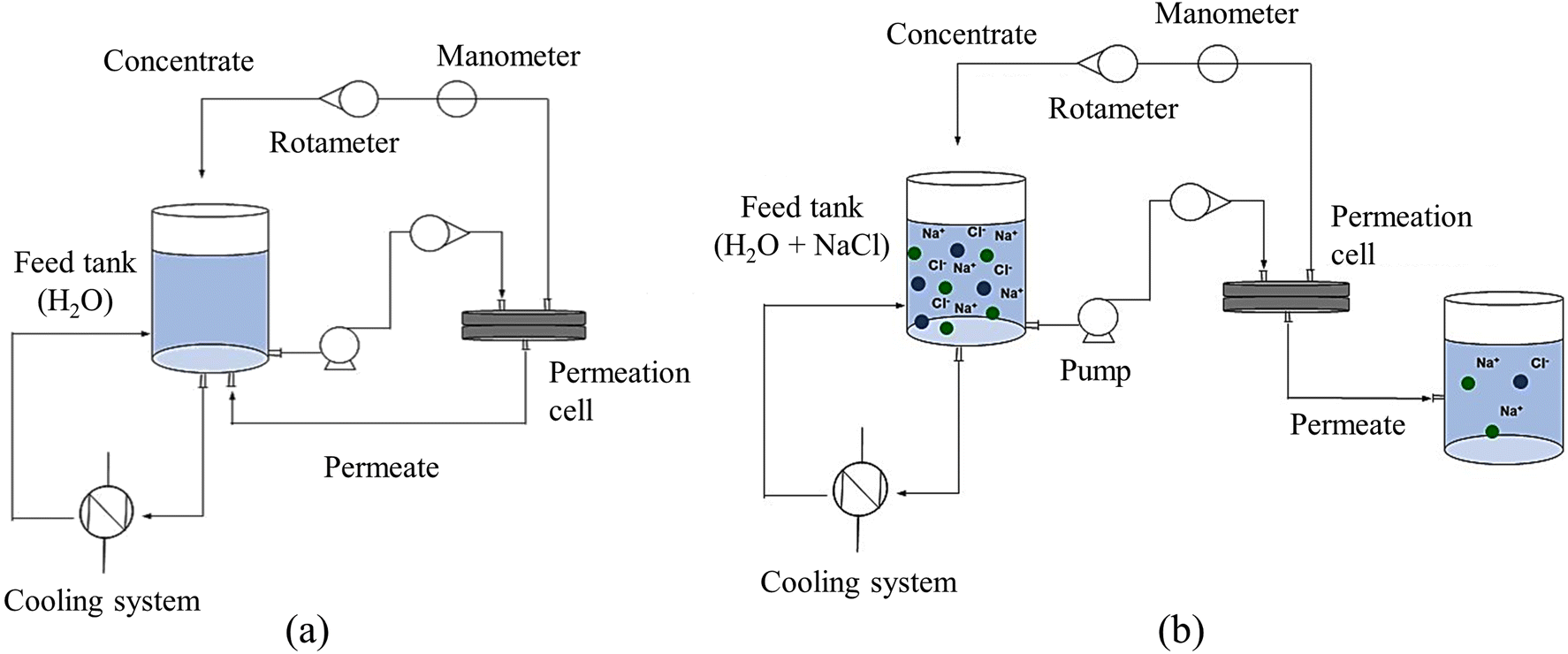 | ||
| Fig. 2 Experimental setups used to evaluate (a) hydraulic permeability and (b) salt rejection of the membranes used in this study. | ||
2.4. Fouling tests
Since the incrustation of organic compounds is typically a time-consuming process, it was simulated in an accelerated manner in this work. Stock solutions of each fouling model were initially prepared at a concentration of 2 g L−1. Bovine serum albumin (BSA, Aldrich) was solubilized in water under stirring at room temperature for 12 h. This solution was then filtered and its pH was adjusted to the range of 6–7. Next, 300 mL of this solution was collected for the subsequent preparation of the synthetic effluent. Humic acid (HA, Aldrich) stock solution was prepared after its dissolution in water under stirring at room temperature for 4 h. To promote complete dissolution, the pH was adjusted to 12 by adding sodium hydroxide. After solubilization, the mixture was centrifuged, 300 mL of the supernatant was separated, and the pH was adjusted to 6–7 by adding hydrochloric acid. Caprylic acid (octanoic acid – OCA, Aldrich) stock solution was prepared after dissolution in water under stirring at room temperature. The solution pH was kept constant at 4 by adding hydrochloric acid.To prepare a 50 mM ionic strength solution for the BSA and HA fouling tests, 1 mM CaCl2 and 47 mM NaCl were added to 2700 mL deionized water. For OCA fouling, a 2700 mL solution was prepared and its ionic strength was also adjusted to 50 mM by adding NaCl. Calcium ions can promote HA and BSA fouling by forming complexes with these molecules.28,29 However, this complexation effect is absent for OCA, requiring the use of NaCl instead of CaCl2 to stabilize the solution.30 Next, the synthetic feed effluent was prepared using the previously obtained stabilization and fouling solutions. This was done by mixing 300 mL of each stock solution with 2700 mL of the stabilization solution, resulting in a feed solution equivalent to 200 mg L−1 of the fouling model foulants for each test. Permeate flow was monitored every 10 min until constant flow was achieved in tests conducted with all fouling models. Throughout these tests, the feed pressure was maintained at 15 bar, the temperature was kept below 28 °C, and the feed flow rate was maintained at 2.4 L min−1. Fig. 3 summarizes the experimental workflow used in this study to evaluate the performance of modified PA membranes.
 | ||
| Fig. 3 Overview of the experimental workflow used to evaluate the performance of modified PA membranes. The process started with the preparation of GO solutions at various concentrations, followed by exfoliation in different solvents. GO was then deposited onto PA membranes using different methods. The modified membranes were subjected to fouling tests with BSA, HA, and OCA. Membrane performance was evaluated by measurements of water flux, salt rejection, chlorine resistance, and surface roughness. | ||
A cleaning procedure to remove the fouling compounds was also carried out. It consisted of immersing the fouled membranes in a citric acid solution (pH 2) for 2 h, followed by soaking them in a sodium hydroxide solution (pH 12) for 2 h. Each membrane was treated with 500 mL of each solution. The membranes were then rinsed thoroughly with water.
2.5. Membrane characterizations
The surface morphology was evaluated by scanning electron microscopy (SEM) using a FEI Quanta 200 Field Emission Gun microscope at an accelerating voltage of 5 kV. The samples were placed on double-sided carbon tapes and sputter coated with a 15 nm thick carbon layer. High-resolution transmission electron microscopy (HRTEM) micrographs were obtained using a JEOL 2100F FEG-TEM at 200 kV with holey-carbon-coated copper grids. The surface roughness was measured by atomic force microscopy (AFM) on an Asylum Research MFP-3D-AS microscope operating in the non-contact mode. A silicon cantilever with a spring constant of 26 N m−1 and a resonant frequency of 30 kHz was used in these tests. Identification of functional groups was performed by Fourier transform infrared (FTIR) spectroscopy using a Perkin Elmer Frontier spectrometer with a resolution of 4 cm−1 and 32 scans. The spectrometer was equipped with an attenuated total reflectance (ATR) accessory and a zinc selenide (ZnSe) crystal reflecting element was used. Thermogravimetric analysis (TGA) was conducted using a TA Q50 instrument, with a heating rate of 1 °C min−1 from room temperature to 800 °C. The experiment was carried out under an argon atmosphere with a flow rate of 20 mL min−1. Derivative thermogravimetric (DTG) profiles were obtained by applying the first derivative to the TG curves.3. Results and discussions
The results of this study are presented as follows. First, we examined the structural properties of the GO suspension prepared in this work. Next, the effect of GO concentration in two different solvents, namely water and 70% aqueous EtOH solution, was investigated. In this first phase, all samples were prepared using the spin coating technique. Then, the most effective system identified in the first phase was further investigated using different deposition techniques. Finally, the fouling by BSA, HA, or OCA was investigated. The performance and structural characteristics of the nanocoated membranes were carefully compared with those of commercially available membranes.3.1. GO characterization
Fig. 4 shows the characterization of the GO suspension used in this study. Fig. 4a shows a TEM micrograph showing that the GO nanosheets used to modify the commercial PA membranes are thin, slightly wrinkled, and have lateral dimensions in the micrometer range. The HRTEM image in Fig. 4b suggests that the GO nanosheets have an average thickness of about two layers. Fig. 4c shows the FTIR spectrum of GO, confirming the presence of functional groups characteristic of GO and verifying the effectiveness of the oxidation process used.31,32 In particular, the absorption band at 1722 cm−1, corresponding to the C![[double bond, length as m-dash]](https://www.rsc.org/images/entities/char_e001.gif) O stretching vibrations of carbonyl and carboxylic acid groups, is prominently observed, indicating successful oxidation. Table 1 summarizes the observed absorption bands and their corresponding assignments to specific chemical groups. Finally, Fig. 4d shows the TGA and DTG profiles, which reveal three distinct mass loss events. The first event, occurring at temperatures up to 100 °C, is attributed to the removal of physisorbed water and other volatile molecules. The second event, between 100 °C and 400 °C, corresponds to the removal of oxygenated groups. The final mass loss event, occurring at temperatures above 400 °C, is due to pyrolytic decomposition of the GO graphitic structure.33
O stretching vibrations of carbonyl and carboxylic acid groups, is prominently observed, indicating successful oxidation. Table 1 summarizes the observed absorption bands and their corresponding assignments to specific chemical groups. Finally, Fig. 4d shows the TGA and DTG profiles, which reveal three distinct mass loss events. The first event, occurring at temperatures up to 100 °C, is attributed to the removal of physisorbed water and other volatile molecules. The second event, between 100 °C and 400 °C, corresponds to the removal of oxygenated groups. The final mass loss event, occurring at temperatures above 400 °C, is due to pyrolytic decomposition of the GO graphitic structure.33
 | ||
| Fig. 4 Summary of the characterization tests performed to evaluate the prepared GO. (a) TEM, (b) HRTEM, (c) FTIR, and (d) TGA-DTG. | ||
| Wavenumber (cm−1) | Chemical bond |
|---|---|
| 3600–2960 | O–H |
| 1722 | CO |
| 1633 | CC |
| 1159 | C–O |
| 1038 | C–O epoxide |
3.2. Effect of solvent and GO concentration
The hydraulic permeability and salt rejection of membranes modified with GO by spin coating are shown in Fig. 5a. The results obtained for the pristine membrane are also shown for reference purposes. It can be observed that the sample modified with GO-EtOH (1 g L−1) has a significantly higher permeability (3.6 L hm−2 bar−1) than the reference membrane (3.1 L hm−2 bar−1), indicating a 16% increase. Nonetheless, salt rejection is lower for the modified sample (96.5%) than for the reference membrane (97.6%). Notably, these results remained unaffected by variations in GO concentration when EtOH was used as the solvent. Therefore, we used the highest concentration of GO (1 g L−1) to achieve superior surface coverage. This improved coverage plays a critical role in maintaining the integrity of the membrane's skin layer, effectively shielding it from the damaging effects of free chlorine attack. A similar trend was observed for GO-coated samples prepared in water, suggesting that the optimal condition is achieved at a concentration of 1 g L−1. Subsequently, we performed a comprehensive characterization of the GO-coated samples prepared in water and EtOH, both at a concentration of 1 g L−1. Structural, morphological, hydraulic permeability, salt rejection, and chemical resistance properties were considered in this characterization. | ||
| Fig. 5 (a) Hydraulic permeability and salt rejection of the reference membrane in bare and spin-coated conditions. (b) Permeability and (c) salt rejection of the membranes before and after short-term exposure to chlorine (10 h – 104 ppm). | ||
The membranes coated with GO-water showed water permeabilities similar to those of the pristine commercial membrane, regardless of the GO concentration. This behavior indicates that the exfoliation of GO in water did not affect the hydraulic permeability of the membranes. In terms of salt rejection, the reference membrane showed higher values than the coated membranes (96.4% for GO-water (1 g L−1) and 97.6% for the pristine membrane). Similar behavior has been already reported for membranes coated with GO-EtOH and GO-water.34 The authors observed that the membrane coated with GO-EtOH showed an increase in water permeability, while the membrane modified with GO-water showed a decrease compared to the reference membrane. Furthermore, the coated membranes showed a slight decrease in salt rejection compared to the reference membrane, which is consistent with our results. Increased adsorption on the GO layer may account for this decrease in salt rejection.
As shown in Fig. 5b, the reference membrane showed a significant increase in permeability when exposed to a 104 ppm NaClO solution for 10 h, changing from 3.1 L hm−2 bar−1 to 98.0 L hm−2 bar−1. Nonetheless, the salt rejection rate decreased from 96.9% to 12.8% after the chlorine attack (Fig. 5c). This dramatic increase in permeability and decrease in selectivity underscores the deleterious effect of chlorine on the PA layer, making its use under such conditions impractical.35 The GO-coated membrane prepared in water (1 g L−1) showed a significant increase in permeability from 2.9 L hm−2 bar−1 to 62.3 L hm−2 bar−1 after chlorine exposure (Fig. 5b). This increase of approximately 2048% is significant, but less pronounced than the more than 3000% increase observed in the reference membrane, which increased from 3.1 L hm−2 bar−1 to 98.0 L hm−2 bar−1. The degradation of the PA skin also had a significant impact on saline rejection, resulting in a reduction from 96.4% to 12.7%, a behavior similar to that observed for the reference sample. In contrast to the other samples, the permeability increase after chlorine exposure was significantly reduced for the GO-coated membrane prepared in EtOH (1 g L−1). The initial permeability of 3.6 L hm−2 bar−1, increased to 11.0 L hm−2 bar−1, a more modest increase of about 206% (Fig. 5b). This trend was also observed for salt rejection, as exposure to chlorine resulted in only a 21% decrease (Fig. 5c). These results support the potential of GO dispersion in EtOH (1 g L−1) to serve as a protective layer on the PA skin. It has been reported that GO effectively prevents the replacement of hydrogen in the N–H bond of the amide groups by chlorine (N–Cl bond), thereby inhibiting skin degradation.36 This protective effect demonstrates the promising role of GO in maintaining membrane integrity under chlorine exposure. It is important to note that in RO desalination plants, seawater typically undergoes a chlorination process with initial doses of less than 1 mg L−1 and contact times of up to 4 h.37–39 In this sense, the conditions applied here were even more severe than in a real plant, highlighting the excellent protective effect of the GO-EtOH layer on PA membranes, which can increase the lifetime of RO systems.
Fig. 6a and b show the hydraulic permeability and salt rejection after long-term exposure to chlorine (102 ppm for 21 days). The observed behavior is consistent with those found during short-term exposure (104 ppm for 10 h). The performance of the reference sample was dramatically affected by the test, showing a 245% increase in hydraulic permeability (from 3.1 L hm−2 bar−1 to 10.7 L hm−2 bar−1) and a 23% reduction in salt rejection (from 96.9 to 74.3%). On the other hand, the membrane coated with GO-EtOH (1 g L−1) showed the best performance with a 69% increase in hydraulic permeability (from 3.6 L hm−2 bar−1 to 6.1 L hm−2 bar−1) and a decrease of only 13% in salt rejection (from 96.4 to 82.6%). This result further highlights the protective potential of GO in maintaining membrane integrity under prolonged exposure to chlorine. The exposure time and NaClO concentration during the chlorine attack are critical aspects to be considered. In particular, it was observed that higher NaClO concentrations resulted in greater membrane damage, as shown in Fig. 5 and 6. However, it is important to note that the GO coating proved to be effective in protecting the PA skin layer from chlorine attack.
 | ||
| Fig. 6 (a) Hydraulic permeability and (b) salt rejection of the membranes before and after long-term exposure to chlorine (21 days – 102 ppm). Inset: FTIR spectra of the membranes before and after the chlorine attack. | ||
The inset in Fig. 6 shows the FTIR spectra of the pristine membrane before and after chlorine exposure. After exposure, several important spectral changes associated with aromatic PA were observed. Specifically, the absorption bands around 3500–3300 cm−1, attributed to N–H and O–H stretching,40–43 and the amide I band around 1660 cm−1, associated with CO stretching and C–N deformation,40,41,43–45 disappeared. The amide II band at 1542 cm−1, mainly due to N–H bonds,40,43,45,46 also decreased. These spectral changes are consistent with the degradation mechanism proposed by Stolov and Freger,47 who suggested that this process involves N-chlorination followed by either C-chlorination under acidic conditions or amide bond scission under alkaline conditions. They observed that N-chlorination decreases membrane polarity and reduces ion permeability, while C-chlorination has the opposite effect. Furthermore, chlorination under acidic conditions can lead to additional reactions, such as direct ring chlorination, in addition to N-chlorination and Orton rearrangement. These chemical transformations, whether by C-chlorination or amide bond scission, ultimately cause an irreversible increase in membrane polarity and a loss of ion rejection efficiency.
The hydroxyl and carboxyl groups on GO can form hydrogen bonds, but the strength of these interactions with the amide groups on PA membranes depends on several factors. While both hydroxyl and carboxyl groups can act as hydrogen bond donors and acceptors, the amide group, due to its polar nature, primarily attracts water molecules through hydrogen bonding. For hydrogen bonding to occur between GO and the PA membrane, the PA surface must have accessible hydrogen donors (from –NH groups) or acceptors (from CO groups). If these are not readily available, the interaction may be weak. In addition, the presence of water in the system may compete with GO for hydrogen bonding sites, reducing the likelihood of direct bonding between GO and PA. Other interactions such as van der Waals forces and electrostatic interactions (if surface charges are present) could also contribute to the overall adhesion between GO and the PA membrane. Further investigation of the conditions that promote hydrogen bond formation, such as surface modification of PA membranes or environmental factors such as pH and ionic strength, may help clarify the underlying mechanisms.
Fig. 7 shows the AFM images and the average roughness (Ra) obtained for the studied membranes before and after a short exposure to chlorine. The degradation of the skin layer of the reference membrane after the chlorine attack can be observed by comparing Fig. 7a and b. The roughness of the reference membrane decreased significantly from 42 ± 2 nm to 6 ± 4 nm (about 86%) after exposure to chlorine. This indicates that the chlorine attack has damaged the skin layer of the membrane, resulting in a smoother surface. For membranes coated with GO dispersed in water (Fig. 7c and d) or EtOH (Fig. 7e and f), Ra was less affected, remaining around 28 nm for the former and 25 nm for the latter. SEM micrographs of the bare membrane and samples spin-coated with GO dispersed in either water or EtOH are shown in Fig. 8. These micrographs show that the reference membrane (Fig. 8a and b) has a degraded PA layer as evidenced by the loss of its characteristic morphology. The SEM images for the GO-coated membranes (Fig. 8c–f) show a homogeneous and uniform coating along the membrane surface, which explains the smaller decrease in salt rejection after chlorine attack for the modified samples. These results support the proposition that GO can protect the PA layer from chlorine attack. However, it is important to note that even a small change in Ra can indicate that NaClO has reacted with PA. This reaction can cause permeability to increase (Fig. 5b) and salt rejection to decrease (Fig. 5c), compromising membrane performance and reducing desalination efficiency. As previously discussed, the degradation of RO membranes due to chlorine exposure is attributed to the cleavage of amide bonds in the polymer backbone, resulting in increased pore size and consequently, decreased selectivity.39
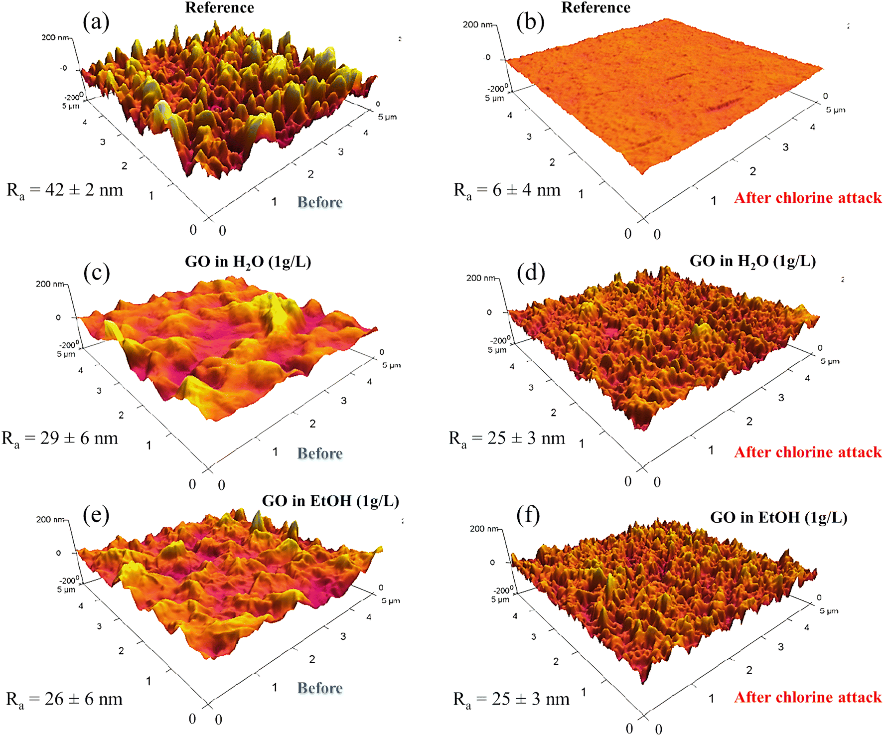 | ||
| Fig. 7 AFM images and average roughness (Ra) of the reference membrane in the bare and spin-coated conditions. (a and b) Reference membrane before and after chlorine attack; (c and d) membrane spin-coated with GO suspension in water (1 g L−1), (e and f) membrane spin-coated with GO suspension in EtOH (1 g L−1). The chlorine attack was performed for 10 h using an aqueous 104 ppm NaClO solution. | ||
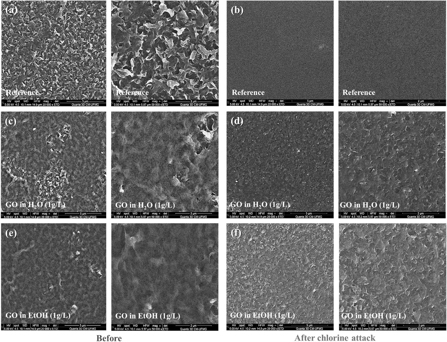 | ||
| Fig. 8 SEM micrographs of uncoated and GO-coated membranes in water or EtOH. Images (a), (c), and (e) show the membranes before chlorine exposure, while images (b), (d), and (f) show the membranes after chlorine exposure. Specifically, (a) and (b) show the untreated membrane; (c) and (d) correspond to the membrane coated with a GO dispersion in water; (e) and (f) correspond to the membrane coated with GO in EtOH. The scale bars in these images are either 2 μm or 5 μm. | ||
Fig. 9a shows the permeability and salt rejection of membranes spin-coated with GO dispersed in either EtOH or IsoOH. Compared to the reference material, the membrane coated with GO-EtOH showed a significant increase in permeability from 2.5 to 3.7 L hm−2 bar−1, a variation of 48%. This increase in permeability is a significant breakthrough in efficiency, which is particularly beneficial for the reduction of energy consumption in membrane separation processes. Similarly, the GO-IsoOH spin-coated membrane also showed an increase in water permeability. However, this increase was more modest at 12% (2.8 L hm−2 bar−1) compared to the membrane spin-coated with GO-EtOH (3.7 L hm−2 bar−1). The higher permeability of the GO spin-coated membrane in EtOH can be attributed to the better dispersion of the GO nanosheets in EtOH compared to IsoOH. EtOH has a greater ability to interact with the hydrophilic groups on the GO nanosheets because it is a more polar solvent than IsoOH. This improved dispersion of the GO nanosheets also results in a more uniform and defect-free coating. The salt rejection achieved by the GO-coated sample in IsoOH was remarkably high, reaching 96.6%. The salt rejection for the GO-modified membrane in EtOH was slightly lower (93.8%). Fig. 9b shows SEM images of GO-coated membranes in EtOH and IsoOH before and after permeation tests in water. Nanosheets are observed in both samples, which is a positive indicator of the stability of the nanostructured coatings. In addition, the surface of the GO-coated membranes is smoother than the rough surface of the pristine commercial membrane (Fig. 7). This observation is further supported by the AFM images in Fig. 9c, where the roughness of the reference membrane is significantly higher than that of the GO-coated samples, approximately 53 nm compared to 28 nm. Nanosheets can also be observed after permeation tests, which is a positive indicator of the stability of nanostructured coatings. Furthermore, this decrease in roughness may represent an important increase in the fouling resistance of the modified samples on the surface.
 | ||
| Fig. 9 (a) Permeability and salt rejection of membranes spin-coated with GO dispersed in either EtOH or IsoOH. (b) SEM images of GO-coated membranes in EtOH and IsoOH before and after permeation tests in water. (c) AFM images comparing the roughness of pristine membranes and GO-coated membranes in EtOH or IsoOH. | ||
The interaction between GO and PA involves both chemical bonding and electrostatic interactions, which significantly improves the chemical stability of GO-modified NF membranes. GO contains hydroxyl and carboxyl groups, which can form hydrogen bonds with the amide groups in the PA backbone, thereby improving the adhesion between the GO layer and the PA membrane.48 In addition, the negatively charged carboxyl groups on GO interact with positively charged sites on the PA membrane, contributing to a more uniform layer. However, in addition to electrostatic interactions, there are several critical factors involved in achieving a uniform GO coating. For example, the distribution of GO nanosheets and their ability to form a continuous coating depends on their lateral size and surface chemistry. It has been reported that the interplay between lateral size and surface chemistry of GO sheets is a critical factor influencing the nanofiltration performance of GO-containing membranes.49 Therefore, precise control of key properties, such as average lateral size and the type and amount of oxygenated functional groups on GO, is essential to optimize membrane quality and performance. In addition, the uniformity of the GO distribution can be affected by the coating method used. For instance, spin coating typically results in a thin and uniform layer due to the centrifugal forces that distribute the material evenly across the surface. On the other hand, dip-coating can result in more localized deposits, depending on the dipping time and withdrawal speed. These aspects should be carefully considered when optimizing the preparation of GO-modified membranes to ensure uniformity and effectiveness of the protective layer.
3.3. Deposition method
The next step in this study was to determine the most promising coating method. In the previous step, dispersion of GO in aqueous EtOH solution (1 g L−1) was found to be the best solvent for coating. Fig. 10a shows the permeability and salt rejection for membranes coated using different techniques (as illustrated by Fig. 1). The best strategy was spin coating, which resulted in a 16% increase in permeability (from 3.1 to 3.6 L hm−2 bar−1) and a minimal decrease in rejection (from 97.6 to 96.8%) compared to the reference material. The permeability and salt rejection of these membranes were also evaluated after exposure to chlorine (Fig. 10b). In several samples, the chlorine attack caused a significant increase in permeability. For the reference sample, the permeability varied from 3.1 L hm−2 bar−1 to 98 L hm−2 bar−1, an increase of about 3060%. The dip-coated sample showed an increase from 2.0 L hm−2 bar−1 to 14.7 L hm−2 bar−1, an increase of 635%. The permeability of the spin-coated sample increased from 3.6 L hm−2 bar−1 to 16.0 L hm−2 bar−1, an increase of 344%. For the drop-cast sample, the permeability increased from 2.2 L hm−2 bar−1 to 12.3 L hm−2 bar−1, an increase of 459%. Finally, the permeability of the filtered sample increased from 1.9 L hm−2 bar−1 to 9.5 L hm−2 bar−1, an increase of 400%. On the other hand, the salt rejection performance decreased as follows: for the reference sample, the salt rejection varied from 97.6% to 12.8%, a decrease of 86.9%. The dip-coated sample decreased from 96.8% to 38.5%, a decrease of 60.2%. The spin-coated sample decreased from 96.5% to 76.5%, a decrease of 20.7%. The salt rejection of the drop-cast sample decreased from 92.9% to 43.8%, a decrease of 52.8%. Finally, the filtered sample showed a reduction from 91.8% to 54.3%, a reduction of 40.8%. These results indicate that spin coating is the most promising technique for protecting PA from chlorine attack. This method resulted in the least significant increase in permeability (344%, from 3.6 L hm−2 bar−1 to 16.0 L hm−2 bar−1) and the smallest decrease in salt rejection (20.7%, from 96.5% to 76.5%) after chlorine exposure.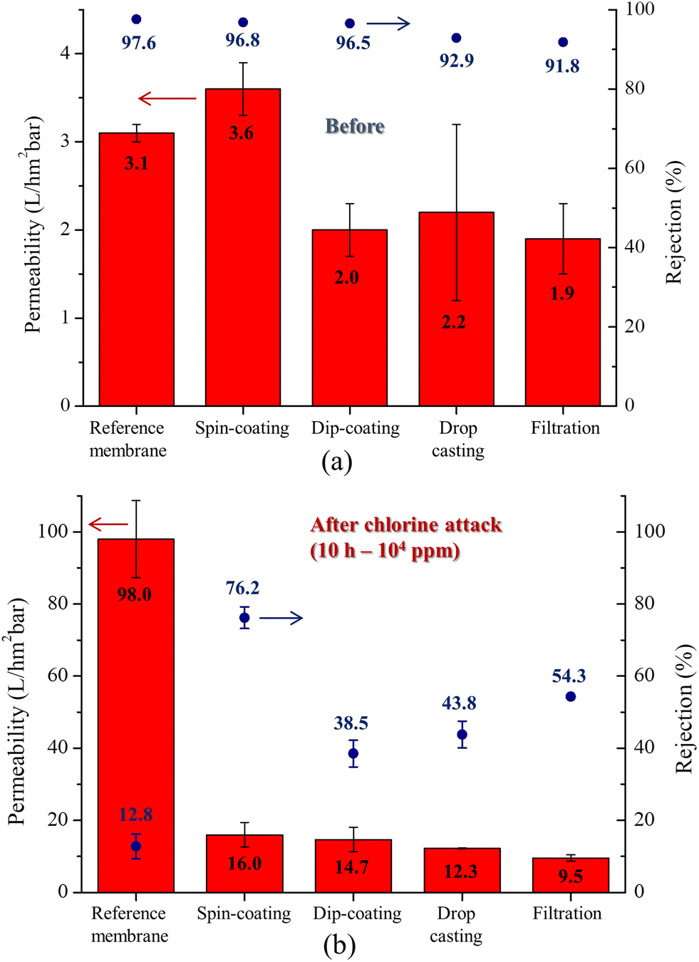 | ||
| Fig. 10 Permeability and salt rejection of membranes coated by different techniques (a) before and (b) after chlorine attack (104 ppm for 10 h). | ||
The AFM images in Fig. 11 reveal that most of the evaluated membranes became smoother after the chlorine attack, with the reference membrane showing the most significant change in roughness (from about 42 nm to 6 nm). The GO-coated membranes by dip-coating and filtration methods displayed a surface roughness variation of about 30 nm to 19 nm and 30 nm to 23 nm, respectively. The roughness of the spin-coated and drop-cast membranes remained relatively unchanged at about 26 nm and 22 nm, respectively. The SEM micrographs in Fig. 12 show that the GO-coated samples retained their morphology after exposure to chlorine. In contrast, the bare membrane showed a significant change in its characteristic surface morphology, accompanied by a significant decrease in roughness. This is an indication that the GO coating protects the PA layer from the harsh conditions of chlorine attack.
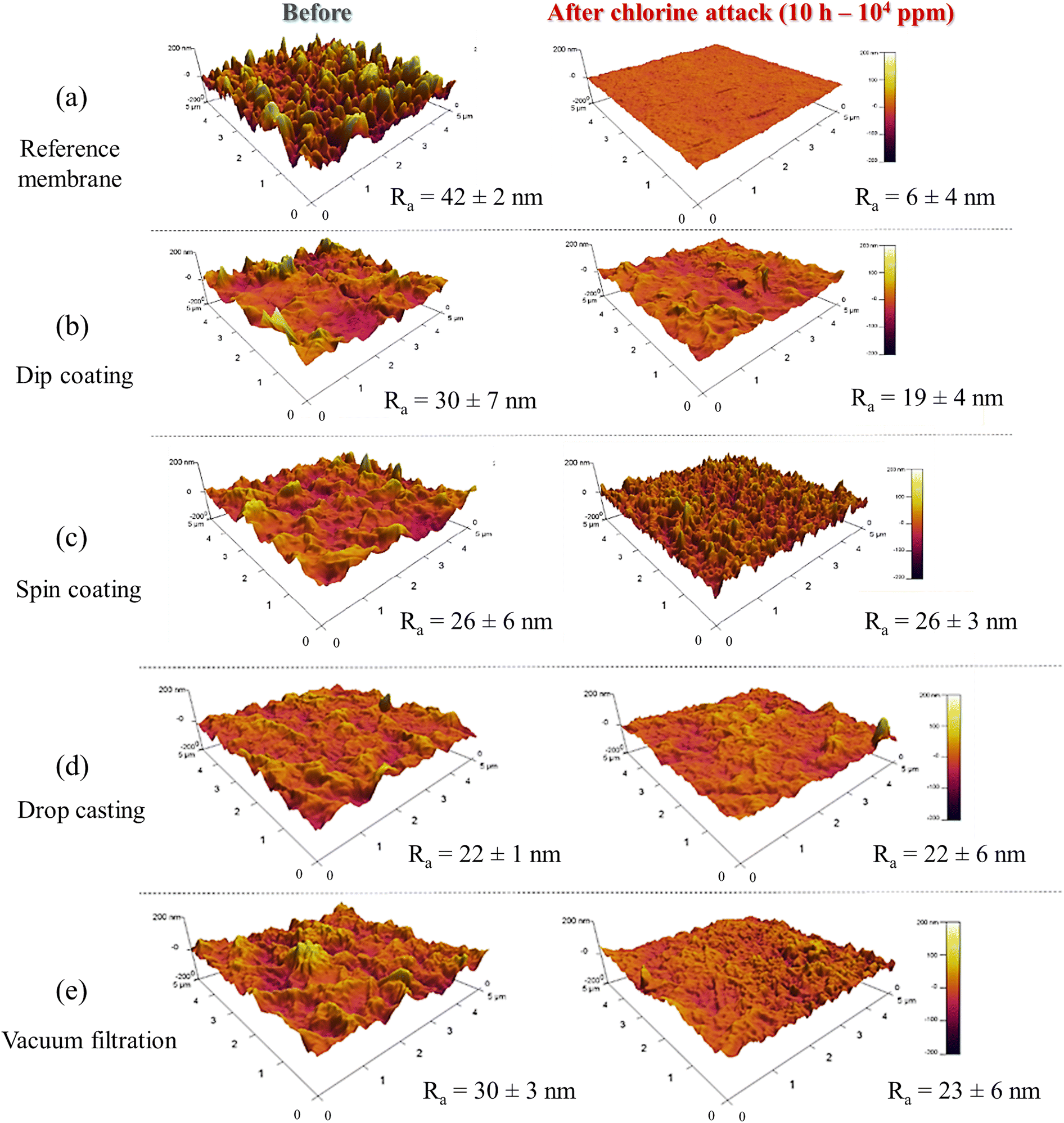 | ||
| Fig. 11 AFM images of the membranes used in this study before and after chlorine attack. (a) Pristine membrane; (b) dip-coated sample; (c) spin-coated sample; (d) drop cast membrane; (e) vacuum-filtered membrane. | ||
 | ||
| Fig. 12 SEM micrographs of bare and GO-coated membranes using different coating techniques. | ||
The improved performance associated with spin coating can be attributed to the effects of external forces applied during the deposition of the GO dispersion, specifically shear and centrifugal forces. These forces synergistically overcome the inherent repulsive electrostatic interactions between the GO nanosheets, resulting in a more homogeneous coating.50,51 The ordered structure of the resulting coating significantly minimizes the occurrence of defects that could compromise membrane integrity and lead to failure. In addition, this coating provides improved protection of the PA layer against chlorine attack. A similar mechanism has been proposed by Shen et al.51 for the preparation of GO membranes designed for gas separation.
3.4. Fouling
Membrane filtration processes for water treatment are significantly affected by the presence of organic matter in the treated medium, resulting in fouling of the membrane surface. This undesirable effect can adversely affect process productivity, increase costs, and degrade water quality.29 Therefore, prevention of fouling is of paramount importance. Here, the permeate flux profile for membranes permeating BSA, HA, and OCA foulant solutions is shown in Fig. 13. These results are expressed as relative flux (J/J0) versus time. For BSA (Fig. 13a), the reference membrane showed a 21% decrease in permeate flux when comparing the initial and final values. In contrast, the membrane coated with GO dispersion in EtOH (1 g L−1) showed only a 14% decrease. This behavior is indicative of the improved fouling resistance due to the modified properties of the GO-coated membrane, such as a reduction in average roughness and an increase in surface charge density. It has been reported that reduced roughness inhibits foulant adhesion while increased surface charge density minimizes organic fouling due to the electrostatic repulsion between the coated membrane surface and organic contaminants.52,53 For example, BSA is negatively charged at pH above 4.8, indicating that this protein will experience electrostatic repulsion near the GO coating, preventing it from fouling the membrane.53 As shown in Fig. 13b, the contrast between the coated membrane and the uncoated membrane was particularly pronounced for HA. This difference can be attributed to the electrostatic repulsion between the negatively charged HA groups and the negatively charged GO groups due to the carboxyl groups present on the GO surface.54 While the reference membrane experienced a significant permeate flux loss of 32%, the coated membrane experienced a significantly lower permeate flux loss of 12%. This behavior underscores the superior resistance of the GO-coated membrane to organic fouling, which contributes to a longer membrane lifetime and minimizes downtime for cleaning and maintenance. Fig. 13c shows the results obtained for OCA, which behaves in a different way than the other foulants used in this study. While the commercial reference membrane showed an 8% decrease in flux, the GO-coated sample maintained its initial flux and even showed a tendency to increase relative flux throughout the test (approximately 20%). The better results obtained by the GO-coated membrane could also be explained by the increase in the electrostatic repulsion between the coating layer and OCA, which decreases the amount of fatty acid deposits on the membrane surface.30,55 | ||
| Fig. 13 Water permeability results for membranes used in fouling tests using (a) BSA, (b) HA, and (c) OCA. | ||
Membranes used in wastewater and natural water treatment often come into contact with organic molecules, including proteins, polysaccharides, humic substances, fatty acids, and other contaminants. This requires a critical evaluation of their fouling behavior. Therefore, a more comprehensive characterization was performed using OCA as a foulant, as fatty acid molecules are one of the most important organic compounds found in water treatment processes.55 The performance of the membranes was evaluated by measuring hydraulic permeability and salt rejection before fouling, after fouling, and after chemical cleaning. The results obtained are summarized in Table 2. Evaluation of the pristine membrane showed a 39% decrease in permeability and a 6% decrease in salt rejection after fouling. In contrast, the membrane coated with GO in EtOH exhibited favorable performance, maintaining permeability with only a 1% loss in salt rejection. This further confirms the improved fouling resistance of the coated membrane, with less fouling on its surface compared to the pristine membrane. Post-fouling cleaning performance was also evaluated. The pristine membrane experienced a 32% decrease in permeability and a 7% decrease in rejection compared to its pre-fouled state. This result suggests that even after cleaning, the membrane was not able to fully recover its initial performance before the fouling test. The coated membrane showed a milder effect, increasing permeability by 14% and decreasing rejection by only 3% after cleaning compared to the pre-fouled membrane. Fig. 14 shows AFM images obtained for the membranes in different conditions. The uncoated membrane has a Ra value of 42 nm, while the coated membrane has a value of 26 nm. This difference is due to the smoothing of the commercial membrane surface by the GO coating. After fouling, both samples showed a significant increase in roughness, where a heterogeneous behavior was also observed, as indicated by the associated standard deviation. This heterogeneity was more pronounced in the reference membrane, resulting in a high standard deviation (44 nm). After cleaning, both the uncoated and the coated membranes showed a reduction in roughness, as expected due to the chemical cleaning process that attempted to restore the initial properties of the membranes.
| Membrane | Before fouling | After fouling | After cleaning | |||
|---|---|---|---|---|---|---|
| Water permeability (L hm−2 bar−1) | Salt rejection (%) | Water permeability (L hm−2 bar−1) | Salt rejection (%) | Water permeability (L hm−2 bar−1) | Salt rejection (%) | |
| Reference | 3.8 | 95.8 | 2.3 | 89.6 | 2.6 | 89.4 |
| GO-coated | 3.0 | 96.4 | 3.0 | 95.3 | 3.4 | 93.1 |
 | ||
| Fig. 14 AFM images obtained for the membranes before fouling (pristine), after fouling, and after chemical cleaning. | ||
It is well known that the improved performance of GO membranes is closely related to the formation of the so-called low friction channels.56 This mechanism is influenced not only by the hydrophilic edges and defects of the GO nanosheets, which serve as entry points for water molecules, but also by the arrangement of the nanosheets and the size of the resulting channels. Once inside, water molecules quickly diffuse through these carbon nanochannels, taking advantage of the low-friction interaction between water and the smooth, graphene-like surfaces, a phenomenon known as the drag reduction effect.57 Given the importance of both structural arrangement and channel size, a promising strategy to further improve the performance of GO membranes would be to develop methods to precisely control the spatial distribution and orientation of GO sheets on the membrane surface. Moreover, one of the major challenges in the large-scale development and implementation of surface-modified membranes is ensuring the stability of the coatings. Industrial-scale membranes operate in pressurized modules in cross-flow filtration mode, subjecting their surfaces to shear stresses in the direction of feed flow. These stresses have the potential to dislodge substances adhering to the membrane surface. Therefore, the bond strength between the membrane surface and the modifying material must exceed the forces attempting to remove the coating. This makes the selection of modifying materials, the polymeric structure of the membrane, and the modification method critical parameters. To assess membrane stability, we examined water samples collected after washing the membranes following their modifications, as well as feed samples taken at various intervals during operation (up to 7 h). These samples were analyzed using UV-vis spectroscopy, which identifies GO by its absorption band around 235 nm. Our analysis confirmed that no GO was detected in the samples throughout the testing period. The original modification dispersions had a concentration of 1000 mg L−1, and the detection limit of the method was 5 mg L−1. The observed stability is attributed to the oxygenated functional groups on the edges of the GO sheets, which can form bonds with other structures and functional groups, such as the amide groups characteristic of aromatic PA.
4. Conclusions
This study has established a solid technological basis for the application of nanostructured GO coatings on commercial PA membranes. We have found that the optimal conditions for achieving the best performance are spin coating as the deposition method, a GO concentration of 1 g L−1, and EtOH as the solvent. This surface modification increases water permeability by up to 50% compared to the reference membrane, which is particularly beneficial for reducing energy consumption in membrane separation processes. In addition, an observed reduction of about 50% in the average surface roughness of the coated membrane underscores the potential increase in fouling resistance. Notably, the membranes exhibited effective shielding against chlorine attack as evidenced by their stability under conditions of exposure to 100 ppm NaClO for 10 h. In addition, results from incrustation tests on the prepared samples show a significant reduction in relative flux for the GO-coated membranes, demonstrating improved resistance to organic incrustation. This improved resistance translates into reduced cleaning costs, minimized downtime for maintenance, and longer membrane life. These results demonstrate the potential of GO coatings to improve the performance of PA membranes in a variety of applications, including water purification and desalination.Data availability
The authors declare that the data supporting the results of this study are available from the corresponding author, Eduardo H. M. Nunes, upon reasonable request.Conflicts of interest
The authors declare no conflicts of interest.Acknowledgements
The authors acknowledge the financial support of CAPES (PROEX), CNPq and Petrobras. We also thank the UFMG Microscopy Center for their invaluable technical assistance in performing the microscopy analyses.References
- T. Peters, Chem. Eng. Technol., 2010, 33, 1233–1240 CrossRef CAS.
- S. Fellaou, A. Ruiz-Garcia and B. Gourich, Desalination, 2021, 506, 114999 CrossRef CAS.
- M. Qasim, M. Badrelzaman, N. N. Darwish, N. A. Darwish and N. Hilal, Desalination, 2019, 459, 59–104 CrossRef CAS.
- Q. Zhao, D. L. Zhao, L. Y. Ee, T.-S. Chung and S. B. Chen, Desalination, 2023, 554, 116515 CrossRef CAS.
- J. Bundschuh, M. Kaczmarczyk, N. Ghaffour and B. Tomaszewska, Desalination, 2021, 508, 115035 CrossRef CAS.
- N. Dhakal, S. G. Salinas-Rodriguez, J. Hamdani, A. Abushaban, H. Sawalha, J. C. Schippers and M. D. Kennedy, Membranes, 2022, 12, 381 CrossRef CAS PubMed.
- D. Rana, T. Matsuura, M. A. Kassim and A. F. Ismail, in Handbook of Membrane Separations: Chemical, Pharmaceutical, Food and Biotechnological Applications, ed. A. K. Pabby, S. S. H. Rizvi and A. M. Sastre, CRC Press, Boca Raton, 2nd edn, 2015, pp. 35–52 Search PubMed.
- D. Li, Y. Yan and H. Wang, Prog. Polym. Sci., 2016, 61, 104–155 CrossRef CAS.
- M. Tawalbeh, L. Qalyoubi, A. Al-Othman, M. Qasim and M. Shirazi, Desalination, 2023, 553, 116460 CrossRef CAS.
- J. Kucera, Reverse osmosis: Design, processes, and applications for engineers, Wiley-Scrivener, 2015 Search PubMed.
- D. Suresh, P. S. Goh, A. F. Ismail, S. B. Mansur, K. C. Wong, M. H. Asraf, N. A. N. N. Malek and T. W. Wong, Desalination, 2022, 543, 116107 CrossRef CAS.
- J. Glater, S. Hong and M. Elimelech, Desalination, 1994, 95, 325–345 CrossRef CAS.
- D. J. Johnson and N. Hilal, Desalination, 2021, 500, 114852 CrossRef CAS.
- A. Ruiz-García and I. Nuez, Desalination, 2020, 489, 114526 CrossRef.
- H.-R. Chae, J. Lee, C.-H. Lee, I.-C. Kim and P.-K. Park, J. Membr. Sci., 2015, 483, 128–135 CrossRef CAS.
- M. E. A. Ali, L. Wang, X. Wang and X. Feng, Desalination, 2016, 386, 67–76 CrossRef CAS.
- S. Bano, A. Mahmood, S.-J. Kim and K.-H. Lee, J. Mater. Chem. A, 2015, 3, 2065–2071 RSC.
- Z. Li, Y. Wang, M. Han, D. Wang, S. Han, Z. Liu, N. Zhou, R. Shang and C. Xie, Front. Chem., 2020, 7, 877 CrossRef PubMed.
- M. Abbaszadeh, D. Krizak and S. Kundu, Desalination, 2019, 470, 114116 CrossRef CAS.
- X. Guo, H. Gao, S. Wang, L. Yin and Y. Dai, Desalination, 2020, 488, 114535 CrossRef CAS.
- Y. Lu, J. Hao, G. Xiao, L. Chen, T. Wang and Z. Hu, Appl. Surf. Sci., 2017, 422, 710–719 CrossRef CAS.
- C. Liang, D. Wei, S. Zhang, Q. Ren, J. Shi and L. Liu, Ecotoxicol. Environ. Saf., 2021, 210, 111885 CrossRef CAS PubMed.
- A. Ruiz-García and I. Nuez, Desalination, 2022, 533, 115768 CrossRef.
- N. R. Sarker, P. Cherukupally, I. Gourevich, J. Wilbur, S. D. Jons and A. M. Bilton, Desalination, 2022, 539, 115956 CrossRef CAS.
- M. A. Al-Obaidi, K. H. Rasn, S. H. Aladwani, M. Kadhom and I. M. Mujtaba, Chem. Eng. Res. Des., 2022, 182, 525–543 CrossRef CAS.
- W. Mao, X. Zou, Z. Guo, S. Sun, S. Ma, S. Lyv, Y. Xiao, X. Ji and Y. Wang, Membranes, 2021, 11, 521 CrossRef CAS PubMed.
- V. G. Castro, J. C. Neves, N. M. Pereira, A. L. S. Assis, L. A. Montoro and G. G. Silva, Process for obtaining graphite oxide and graphene oxide: Products and uses, Br. Pat., 102016005632-2A2, Universidade Federal de Minas Gerais, 2017 Search PubMed.
- Y. Wang, X. Zheng, D. Li, J. Tian, H. Wu and Y. Zhang, Desalination, 2023, 548, 116236 CrossRef CAS.
- K. Katsoufidou, S. G. Yiantsios and A. J. Karabelas, Desalination, 2008, 220, 214–227 CrossRef CAS.
- W. S. Ang and M. Elimelech, Water Res., 2008, 42, 4393–4403 CrossRef CAS PubMed.
- M. M. Viana, M. C. F. S. Lima, J. C. Forsythe, V. S. Gangoli, M. Cho, Y. Cheng, G. G. Silva, M. S. Wong and V. Caliman, J. Braz. Chem. Soc., 2015, 26, 978–984 CAS.
- V. H. Pham, T. V. Cuong, S. H. Hur, E. Oh, E. J. Kim, E. W. Shin and J. S. Chung, J. Mater. Chem., 2011, 21, 3371–3377 RSC.
- V. Panwar, A. Chattree and K. Pal, Phys. E, 2015, 73, 235–241 CrossRef CAS.
- F. Shao, L. Dong, H. Dong, Q. Zhang, M. Zhao, L. Yu, B. Pang and Y. Chen, J. Membr. Sci., 2017, 525, 9–17 CrossRef CAS.
- V. T. Do, C. Y. Tang, M. Reinhard and J. O. Leckie, Environ. Sci. Technol., 2012, 46, 13184–13192 CrossRef CAS PubMed.
- J. Powell, J. Luh and O. Coronell, Environ. Sci. Technol., 2015, 49, 12136–12144 CrossRef CAS PubMed.
- E. Agus and D. L. Sedlak, Water Res., 2010, 44, 1616–1626 CrossRef CAS PubMed.
- E. Agus, N. Voutchkov and D. L. Sedlak, Desalination, 2009, 237, 214–237 CrossRef CAS.
- M. Al-Abri, B. Al-Ghafri, T. Bora, S. Dobretsov, J. Dutta, S. Castelletto, L. Rosa and A. Boretti, npj Clean Water, 2019, 2, 2 CrossRef CAS.
- G.-D. Kang, C.-J. Gao, W.-D. Chen, X.-M. Jie, Y.-M. Cao and Q. Yuan, J. Membr. Sci., 2007, 300, 165–171 CrossRef CAS.
- Y. Jin and Z. Su, J. Membr. Sci., 2009, 330, 175–179 CrossRef CAS.
- P. S. Singh, S. V. Joshi, J. J. Trivedi, C. V. Devmurari, A. P. Rao and P. K. Ghosh, J. Membr. Sci., 2006, 278, 19–25 CrossRef CAS.
- C. Y. Tang, Y.-N. Kwon and J. O. Leckie, Desalination, 2009, 242, 149–167 CrossRef CAS.
- Y.-N. Kwon and J. O. Leckie, J. Membr. Sci., 2006, 283, 21–26 CrossRef CAS.
- A. Antony, R. Fudianto, S. Cox and G. Leslie, J. Membr. Sci., 2010, 347, 159–164 CrossRef CAS.
- A. Ettori, E. Gaudichet-Maurin, J.-C. Schrotter, P. Aimar and C. Causserand, J. Membr. Sci., 2011, 375, 220–230 CrossRef CAS.
- M. Stolov and V. Freger, Environ. Sci. Technol., 2019, 53, 2618–2625 CrossRef CAS PubMed.
- S. J. A. Hocker, N. V. Hudson-Smith, P. T. Smith, C. H. Komatsu, L. R. Dickinson, H. C. Schniepp and D. E. Kranbuehl, Polymer, 2017, 126, 248–258 CrossRef CAS PubMed.
- V. Kandjou, Z. González, B. Acevedo, J. M. Munuera, J. I. Paredes and S. Melendi-Espina, J. Taiwan Inst. Chem. Eng., 2021, 119, 158–165 CrossRef CAS.
- O. Kwon, Y. Choi, E. Choi, M. Kim, Y. C. Woo and D. W. Kim, Nanomaterials, 2021, 11, 757 CrossRef CAS PubMed.
- J. Shen, G. Liu, K. Huang, Z. Chu, W. Jin and N. Xu, ACS Nano, 2016, 10, 3398–3409 CrossRef CAS PubMed.
- E. Igbinigun, Y. Fennell, R. Malaisamy, K. L. Jones and V. Morris, J. Membr. Sci., 2016, 514, 518–526 CrossRef CAS.
- W. Choi, J. Choi, J. Bang and J.-H. Lee, ACS Appl. Mater. Interfaces, 2013, 5, 12510–12519 CrossRef CAS PubMed.
- K. H. Chu, Y. Huang, M. Yu, N. Her, J. R. V. Flora, C. M. Park, S. Kim, J. Cho and Y. Yoon, ACS Appl. Mater. Interfaces, 2016, 8, 22270–22279 CrossRef CAS PubMed.
- K. Ruengruehan, H. Kim, L. T. Hai Yen, A. Jang, W. Lee and S. Kang, Desalin. Water Treat., 2016, 57, 7531–7537 CrossRef CAS.
- X. Han and Z. Guo, Carbon, 2021, 172, 647–681 CrossRef CAS.
- S. Castelletto and A. Boretti, RSC Adv., 2021, 11, 7981–8002 RSC.
| This journal is © The Royal Society of Chemistry 2025 |