 Open Access Article
Methanol-based thermoelectric conversion device with high power†
Touya
Aiba
a,
Haruka
Yamada
b and
Yutaka
Moritomo
 *abcd
*abcd
aGraduate School of Pure & Applied Science, University of Tsukuba, Tennodai 1-1-1, Tsukuba, Ibaraki 305-8571, Japan. E-mail: moritomo.yutaka.gf@u.tsukba.ac.jp
bSchool of Science & Engineering, University of Tsukuba, Tennodai 1-1-1, Tsukuba, Ibaraki 305-8571, Japan
cFaculty of Pure & Applied Science, University of Tsukuba, Tennodai 1-1-1, Tsukuba, Ibaraki 305-8571, Japan
dTsukuba Research Center for Energy Materials Science (TREMS), University of Tsukuba, Tsukuba, Ibaraki 305-8571, Japan
First published on 22nd November 2024
Abstract
A liquid thermoelectric conversion device (LTE) converts environmental heat into electric power via the electrochemical Seebeck coefficient α. The maximum power (Wmax) is expressed as  , where ΔT and R′ are the temperature difference between electrodes and device resistance in operation, respectively. Here, we systematically investigated the resistance components of LTEs composed of aqueous, methanol (MeOH) and acetone solutions containing 0.8 M Fe(ClO4)2/Fe(ClO4)3. We found that the charge transfer resistance Rct of the MeOH LTE is the smallest among the three LTEs. We demonstrated that the Wmax of the MeOH LTE is slightly larger than or comparable with that of the corresponding aqueous LTE. We further discussed the effects of the convection of an electrolyte on R′.
Keywords: Liquid thermoelectric conversion; Methanol; Resistivity components; Coated electrode.
1 Introduction
Energy harvesting devices are extensively investigated from the viewpoint of achieving the sustainable development goals (SDGs). Among the devices, liquid thermoelectric conversion devices (LTEs)1–5 have a simple device structure in which a redox-dissolved electrolyte is sandwiched between two electrodes. LTEs utilize the thermogalvanic effect (electrochemical Seebeck coefficient α) at each electrode to convert temperature differences ΔT between the electrodes into thermal voltage or electric power W. The research of LTE is increasingly active with significant progress.6–23 The performance of LTE is determined by α, effective electric conductivity σ, and effective thermal conductivity κ of the electrolyte. The term “effective” is used because the convection of the electrolyte due to gravity affects σ and κ in an actual LTE in operation.24–26 The maximum power (Wmax) is expressed as , where R′ is the device resistance in operation. To increase Wmax, it is effective to increase α or to decrease R′. α is expressed as
  , where ΔS and e (>0) are the entropy change at the reduction reaction of the redox couple and elementary charge.
In a non-operating LTE at ΔT = 0 K without electrolyte convection, the device resistance (R) can be decomposed into solution resistance Rs, charge transfer resistance Rct, and diffusion resistance Rdif.27 Similar to the resistance in a solid, Rs is determined by the balance between the electric force and frictional force. Then, Rs is proportional to the electrode distance d.28 On the other hand, Rct and Rdif are governed by the redox reaction kinetics in the vicinity of the electrode, and are independent of d. As the reaction progresses, the concentration of reactants/products at the electrode surface changes in a way that prevents further reaction. The resultant concentration gradient drives the diffusion of reactants from (products into) the bulk region, causing Rdif. In a LTE in operation, R′ is further influenced by the electrolyte convection driven by ΔT,25,26 which causes mass transfer and tends to make the concentration in the electrolyte uniform.
Aqueous solutions containing Fe2+/Fe3+ are most extensively investigated as electrolytes for LTE, because Fe2+/Fe3+ is inexpensive and aqueous LTE shows high σ. Kim et al.20 reported that α and σ of Fe2+/Fe3+ aqueous solutions become larger when ClO4− is the counter anion. Buckingham et al.21 demonstrated that α of Fe2+/Fe3+ aqueous solutions can be optimized by the pH of the electrolyte. Jung et al.22 reported that FeCN coated carbon cloth shows small Rct in Fe2+/Fe3+ aqueous solution. Aiba et al.28 reported that R of graphite-dispersing coated electrodes steeply decreases as the electrode thickness t increases below t ≤ 100 μm. On the other hand, Wake et al.,18,19 systematically investigated α and σ of organic solutions containing Fe(ClO4)2/Fe(ClO4)3. They found that the σ (= 34.6 mS cm−1 at 0.7 M) of methanol (MeOH) solution is the highest among those of 11 organic solutions. In addition, the α values of MeOH (1.85 mV K−1 at 0.5 M) and acetone (2.88 mV K−1 at 0.1 M) are much higher than the α (= 1.56 mV K−1 at 0.5 M) of aqueous solution. Therefore, MeOH and acetone LTEs are alternative LTE candidates with high Wmax.
In this paper, we systematically investigated the resistance components of LTEs composed of aqueous, MeOH and acetone solutions containing 0.8 M Fe(ClO4)2/Fe(ClO4)3. We found that the Rct of the MeOH LTE is the smallest among the three LTEs. We demonstrated that the Wmax of the MeOH LTE is slightly larger than or comparable with that of the corresponding aqueous LTE. We further discussed the effects of the electrolyte convection on R′.
2 Results and discussion
2.1 Resistance components against temperature
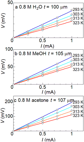
Fig. 1a shows the current I–voltage V plots at ΔT = 0 K in (a) aqueous, (b) MeOH, and (c) acetone solutions containing 0.8 M Fe(ClO4)2/Fe(ClO4)3 at different temperatures T. s and d were 42 mm2 and 10 mm, respectively. At all temperatures, V increases in proportion to I. R was evaluated from the slope of the plot, as indicated by straight lines. R steeply decreases as T increases.
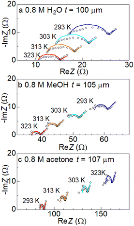
Fig. 2 shows the Cole–Cole plots of complex impedance in (a) aqueous, (b) MeOH, and (c) acetone solutions containing 0.8 M Fe(ClO4)2/Fe(ClO4)3 at different T. s and d were 42 mm2 and 10 mm, respectively. The Cole–Cole plot in (a) aqueous solution at 293 K shows a prototypical shape. The plot shows a semicircle at the left side and a straight line with an inclination of 45 degrees at the right side. The resistances at the left and right sides of the semicircle correspond to Rs and Rs + Rct, respectively. Solid curves are the results of least-squares fits with a Randles equivalent circuit composed of Rs, Rct, electric double layer capacitance Cd, and Warburg impedance ZW. ZW is expressed as ZW = AW(ω−1/2 − iω−1/2), where AW is the Warburg coefficient. The feature of the observed impedance is reproduced by the Randles equivalent circuit model. Similar behaviors are also observed at difference T and in different solutions. One may notice that the observed semicircle in (a) aqueous solution is slightly flattened as compared with the calculated one. The deviation between them can be improved if we replace Cd with constant phase element (CPE) Q, as shown in Fig. S4.†Q is expressed as  where ω is the angular velocity. Y0 and n are frequency-independent constants. Q becomes pure capacitance at n = 1. We note that there is little change in Rs and Rct between the Cd and CPE models (Table S1†).
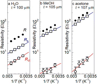
Fig. 3 shows R (filled circles), Rs (open squares), and Rct (open circles) against  in (a) aqueous, (b) MeOH, and (c) acetone solutions containing 0.8 M Fe(ClO4)2/Fe(ClO4)3. In (a) aqueous solution, R, Rs, and Rct increase as
  increases. We evaluated the activation energy Δi (i = s and ct) by least-squares fits with activation-type functions,
  [solid curves in Fig. 3a]. The activation energies are determined as Δs = 1550 K and Δct = 1730 K. Similar behaviors are observed in (b) MeOH and (c) acetone solutions even though Rct is scattered at higher temperatures. In (b) MeOH solution, the activation energies are Δs = 1380 K and Δct = 1360 K. In (c) acetone solution, the activation energies are Δs = 1830 K and Δct = 2420 K.
Here, let's consider the solution dependence of the resistance components. The magnitudes of R and Rs gradually increase in the order aqueous, MeOH, and acetone solutions. We note that Rct in MeOH solution is the smallest among the three solutions.
Here, we recall that the magnitude of Rs is proportional to d (ref. 28) and can be reduced by reducing d. Then, it may be possible to make the R of the MeOH LTE comparable to or smaller than that of the aqueous LTE. Thus, the MeOH LTE with small d is a promising LTE candidate with high Wmax.
2.2 Scaling relation between Rs and viscosity η
Now, let us discuss the solution parameter that governs the magnitude of Rs. In bulk solution, the j-th ion feels both the electric force (= |zj|eE, where |zj|, e, and E are the charge number of the j-th ion, elementary charge, and electric field, respectively) and frictional force proportional to the velocity vj of the j-th ion. According to Stokes' law, the frictional force is given as 6πηrjvj, where η and rj are the viscosity of the solution and effective radius of the j-th ion, respectively. Then, the mobility of the j-th ion is given as
  . On the other hand, Rs−1 is expressed as
  ,27 where F and cj are the Faraday constant and molar concentration of the j-th ion, respectively. By substituting
  , we obtain
  . Note that cj and zj are fixed in the present investigation. If the solution dependence of rj can be ignored, Rs is proportional to η.
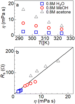
Fig. 4(a) shows η against T in aqueous (open squares), MeOH (open circles), and acetone (open triangles) solutions containing 0.8 M Fe(ClO4)2/Fe(ClO4)3. The T-dependence of η was evaluated using a sine-wave vibro viscometer (SV-10; A&D Company Limited) equipped with a heat bath. In all solutions, η steeply decreases with T. Fig. 4b shows the correlation between η and Rs. Open squares, circles, and triangles represent the η of aqueous, MeOH and acetone solutions containing 0.8 M Fe(ClO4)2/Fe(ClO4)3, respectively. As shown by the straight line, Rs increases almost linearly with η regardless of the solvent type. This observation indicates that the magnitude of Rs is governed by the η of the solution. In other words, the development of low-η solution would lead to a reduction in Rs. We note that the scaling relationship between η and Rs does not hold in the dilute solution. The η of the solvent increases in the order acetone (0.32 mPa s), MeOH (0.62 mPa s) and water (1.01 mPa s). Nevertheless, R is the smallest in aqueous solution even at 0.1 M.18
2.3 Resistance components of MeOH solution against t
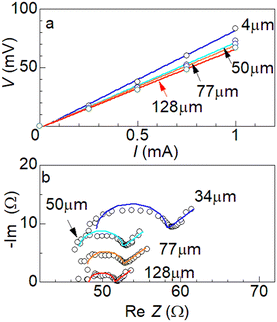
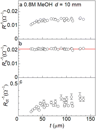
Fig. 4a shows the I–V plots at different t in 0.8 M Fe(ClO4)2/Fe(ClO4)3 MeOH solution at 298 K. s and d were 42 mm2 and 10 mm, respectively. For all electrodes, V increases in proportion to I. R was evaluated from the slope of the plot. Importantly, R decreases as t increases. Fig. 4b shows the Cole–Cole plots of complex impedance at different t in 0.8 M Fe(ClO4)2/Fe(ClO4)3 MeOH solution at 298 K. s and d were 42 mm2 and 10 mm, respectively. Solid curves are the results of least-squares fits with a Randles equivalent circuit composed of Rs, Rct, Cd, and Zω. The observed impedance is well reproduced by the Randles equivalent circuit model.Fig. 6a shows R−1 against t. R−1 slightly increases as t increases in the small t region (t ≤ 60 μm), and then is saturated to about 0.014 Ω−1. Fig. 5b shows Rs−1 against t. Rs−1 (= 0.021 Ω−1) is almost independent of d, because the macroscopic electric force between the electrodes is independent of the electrode structure. A similar t-independent behavior of Rs is observed in 0.8 M Fe(ClO4)2/Fe(ClO4)3 aqueous solution.28
Fig. 6c shows Rct−1 against t. In the small t region (t ≤ 50 μm), Rct−1 increases as t increases. In the large t region (t ≥ 50 μm), however, Rct−1 is seriously scattered. This is probably because the degree of dispersion of the graphite particles varies from electrode to electrode, causing the scattering if the data were plotted against t. On the other hand, Rct−1 is expected to increase in proportion to the electrochemically active surface area (EASA), which is usually evaluated by the Cd of the electrode.29–31 We investigated a correlation between Cd and t [Fig. S5a†] and correlation between Cd and Rct−1 [Fig. S5b†]. We found that the correlation between Cd and t is poor, supporting our idea that the degree of dispersion varies from electrode to electrode. Nevertheless, we found a good correlation between Cd and Rct−1, indicating that Rct−1 is proportional to the EASA.
2.4 Output characteristics of MeOH LTE
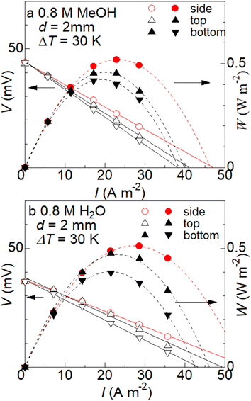
First, let us investigate the effect of the LTE orientation on output power W. Fig. 7a shows the output characteristics of MeOH whose d is 2 mm. The high (TH) and low (TL) electrodes were 298 K and 328 K, respectively. ΔT was fixed at 30 K. The electrolyte is MeOH solution containing 0.8 M Fe(ClO4)2/Fe(ClO4)3. The circles were the data of horizontally oriented LTEs (denoted as “side”). The triangles and inverted triangles were the data of vertically oriented LTEs whose TH-electrode is at the top and bottom, respectively. In both the LTEs, does not show any orientation dependence. The α values of the MeOH (aqueous) LTE are 1.48 (1.22), 1.48 (1.25), and 1.48 (1.22) mV K−1 in the side, top, and bottom configurations, respectively. This is because α is governed by the entropy change at the reduction reaction and is not affected by the electrolyte convection. On the other hand, W shows significant orientation dependence. We evaluated the V0 and R′ of the LTE in operation by least-squares fit of the I–V plot.
  steeply decreases in the order side (0.52 W m−2), top (0.45 W m−2), and bottom (0.42 W m−2) configurations. A similar orientation effect is also observed in the aqueous LTE whose d is 2 mm (Fig. 7b). Wmax steeply decreases in the order side (0.51 W m−2), top (0.46 W m−2), and bottom (0.40 W m−2) configurations.
The observed orientation effect can be ascribed to the convection of the electrolyte caused by gravity. Yang et al.25 investigated the convection effect on W through fluid simulations. In a horizontally oriented LTE, the direction of temperature difference is perpendicular to that of gravity. Then, the electrolyte near the TH-electrode rises, and then moves to the TL-electrode when it reaches the top of the electrode. The electrolyte near the TL-electrode descends, and moves to the TH-electrode when it reaches the bottom of the electrode. The resultant uniform convection throughout the electrolyte effectively carries consumed redox ions to the respective electrode and promotes the redox reaction there. In a vertically oriented LTE, the direction of temperature difference is parallel to that of gravity, and hence, uniform convection throughout the electrolyte is difficult. Then, the redox reaction at the electrode is not promoted as much, because consumed ions are not sufficiently supplied by the electrolyte convection. Consistent with our observation, their simulation25 showed that W decreases in the order side, top, and bottom configurations.
Next, let us compare the Wmax of (a) MeOH LTE with that of (b) aqueous LTE. In the side configuration, the Wmax (= 0.52 W m−2) of the MeOH LTE is comparable with the Wmax (= 0.51 W m−2) of the corresponding aqueous LTE. In the top configuration, the Wmax (= 0.45 W m−2) of the MeOH LTE is comparable with the Wmax (= 0.46 W m−2) of the corresponding aqueous LTE. In the bottom configuration, the Wmax (= 0.42 W m−2) of the MeOH LTE is 5% larger than the Wmax (= 0.40 W m−2) of the corresponding aqueous LTE. Thus, we demonstrated that the Wmax of the MeOH LTE is slightly larger than or comparable with that of the corresponding aqueous LTE. The large Wmax of the MeOH LTE is ascribed to the large α and small Rct, because the former causes high V0 and the latter causes small R′. In Table 1, we compare the obtained Wmax of the MeOH LTE with those of aqueous LTEs containing Fe2+/Fe3+ reported in the literature. We note that the effective electric conductivity σ strongly depends on d and ΔT, reflecting that Rct and Rdif are independent of d and the convection effect is driven by ΔT. Therefore, a direct comparison of Wmax evaluated at different d and ΔT is difficult. Roughly speaking, however, the Wmax of the MeOH LTE is comparable with those of aqueous LTEs reported so far.
The dimensionless figure of merit  is a significant parameter of LTE, since ZT determines the thermal efficiency η. Nishitani et al.32 reported the κ of several solutions containing Fe2(ClO4)2/Fe3(ClO4)3. The κ values at 0.8 M are 0.23 and 0.46 W m−1 K−1 in the MeOH and aqueous solutions.
  of the MeOH and aqueous LTEs can be evaluated from Fig. 7: α = 1.48 and 1.22 mV K−1, respectively.
  of the MeOH and aqueous LTEs can be evaluated from Table 2: σ = 0.213 and 0.280 S cm−1 in the side configuration. We obtained ZT = 0.040 and 0.018 in the MeOH and aqueous LTEs, respectively. The larger ZT in the MeOH LTE is ascribed to the smaller κ of MeOH solution.
| R′ (Ω) | R (Ω) | ||||
|---|---|---|---|---|---|
| Side | Top | Bottom | T L | T H | |
| MeOH | 22.4 | 25.9 | 27.7 | 27.3 | 20.8 |
| H2O | 17.0 | 18.2 | 20.2 | 18.6 | 13.5 |
2.5 Resistance components of LTE in operation
Table 2 shows the R′ of the operating LTEs (ΔT = 30 K) and the R of the non-operating LTE. We carefully performed a series of measurements using the same LTE. Looking at Table 2, one may notice a significant orientation dependence of R′; R′ decreases in the order side, top, and bottom configurations. As discussed in the previous subsection, the orientation effect can be ascribed to the electrolyte convection driven by ΔT. We further investigated the ΔT dependence of R′ in the side configuration with fixing TL at 298 K (Fig. S6†). In the MeOH and aqueous LTEs, R′ decreases as ΔT increases: R′ = 26.8 (20.3), 24.4 (18.2), and 22.4 (15.6); Ω at ΔT = 10, 20 and 30 K, respectively. It is reasonable that the convection effect becomes stronger (R′ becomes smaller) as ΔT increases. We further performed EIS measurements of the operating and non-operating LTEs. The Cole–Cole plot of the operating LTE is almost the same as that of the non-operating LTE at (Fig. S7†). In the MeOH and aqueous LTEs, Rs = 6.4–6.6 (3.4) Ω and Rct = 3.2–3.5 (4.8) Ω, respectively. Therefore, the convection effect in the operating LTE mainly affects Rdif, but has little effect on Rs and Rct.
Finally, let us compare R′ with the average value of R at TL and TH. In the MeOH LTE, R′ in the top and bottom configurations is larger than the average (= 24.1 Ω). In the aqueous LTE, R′ in the top and bottom configurations is larger than the average (= 16.1 Ω). This means that the electrolyte convection has an enhancing effect on Rdif, in addition to the aforementioned suppressing effect.25 As the redox reaction progresses, the concentration of reactants/products at the electrode surface changes in a way that prevents further reaction. The resultant concentration gradient drives the diffusion of reactants from (products into) the bulk region, causing Rdif. The electrolyte convection also enhances the mass transfer of the reactants/products, causing the suppressing effect on Rdif. On the other hand, the electrolyte convection tends to make the concentration in the electrolyte uniform and to suppress the concentration gradient in the vicinity of the electrode. This may be the origin of the enhancing effect on Rdif.
3 Conclusions
In conclusion, we systematically investigated the resistance components of LTEs composed of aqueous, MeOH and acetone solutions containing 0.8 M Fe(ClO4)2/Fe(ClO4)3. We found that the Rct of the MeOH LTE is the smallest among the three LTEs. We demonstrated that the Wmax of the MeOH LTE (d = 2 mm) is slightly larger than or comparable with that of the corresponding aqueous LTE. The MeOH LTE with small d is a promising LTE candidate with high Wmax.4 Experimental section
4.1 Coated electrode and electrolyte
Graphite powder (CAS RN: 7782-42-5, Wako Special Grade) was purchased from FUJIFILM Wako Corp. and used as received. The Raman scattering spectrum (Fig. S1†) at room temperature shows two characteristic bands at 1350 cm−1 and 1580 cm−1. The former and the latter bands are ascribed to the disorder (D) and graphene (G) bands, respectively. The intensity of the D band is much smaller as compared with that of the G band, indicating a small content of the defects.The graphite powder and polyvinylidene difluoride (PVDF) were mixed thoroughly in a ratio of 9![[thin space (1/6-em)]](https://www.rsc.org/images/entities/char_2009.gif) :
:![[thin space (1/6-em)]](https://www.rsc.org/images/entities/char_2009.gif) 1 with N,N-dimethylformamide (DMF).28 The mixture was coated onto stainless steel foil (SUS304, 10 μm) with the use of a coating machine. Then, the electrode was dried in vacuum at 60 °C. The electrode thickness t, which was evaluated with a micrometer, was controlled by the roll height of the machine. Except for the measurement of the t-dependence of the resistance components, t was fixed at ≈ 100 μm. Fig. S2† shows the cross sectional and surface scanning electron microscopy (SEM) images of the electrode (t = 131 μm). The electrode consists of graphite particles with uneven surfaces. The size distribution of the particles was determined to be 19 ± 12 μm from 40 particles.
1 with N,N-dimethylformamide (DMF).28 The mixture was coated onto stainless steel foil (SUS304, 10 μm) with the use of a coating machine. Then, the electrode was dried in vacuum at 60 °C. The electrode thickness t, which was evaluated with a micrometer, was controlled by the roll height of the machine. Except for the measurement of the t-dependence of the resistance components, t was fixed at ≈ 100 μm. Fig. S2† shows the cross sectional and surface scanning electron microscopy (SEM) images of the electrode (t = 131 μm). The electrode consists of graphite particles with uneven surfaces. The size distribution of the particles was determined to be 19 ± 12 μm from 40 particles.
The electrolytes were aqueous, MeOH, and acetone solutions containing 0.8 M Fe(ClO4)2·6.0H2O and 0.8 M Fe(ClO4)3·7.1H2O. The solutes and solvent were purchased from FUJIFILM Wako Corp. and used as received. The solute concentration (= 0.8 M) was selected because the Wmax of the aqueous LTE shows a maximum around 0.8 M.9
4.2 Fabrication of LTE
Resistance and output characteristics of LTE were investigated with a specially-designed two-pole cell (Fig. S3†).33 The cell consists of a cylindrical electrolyte tank and two electrode plates. The electrolyte tank was a 7.3 mm ϕ polytetrafluoroethylene (PTFE) cylinder. The electrode plate was a Pt disk, whose inner surface was completely covered with the coated electrodes. An aluminum base is attached to the outside of each Pt electrode, and a Peltier element and a cooling fan are attached to the base. The temperatures of the high (TH) and low (TL) electrodes were independently controlled with the Peltier element and cooling fan. TH and TL were monitored with T-type thermocouples. The electrode area s was 42 mm2. The electrode distance d was 10 mm or 2 mm.4.3 Device resistance and resistance components
Device resistance, i.e., R at ΔT = 0 and R′ at finite ΔT, was evaluated from the current I–voltage V relation. In the measurement of R, TL and TH were fixed at T. The slope of the I–V plot corresponds to R. The measurement of R was performed with horizontally oriented LTE (side configuration). In the measurement of R′, TL was fixed at 298 K. With the open circuit voltage V0 as the reference, V changed in proportion to I. The slope of the I–V plot corresponds to R′. We further investigated the orientation and ΔT dependence of R′.Resistance components, i.e., Rs and Rct, were evaluated by electrochemical impedance spectroscopy (EIS) with the use of a potentiostat (Vertex.One.EIS, Ivium Technologies). In the EIS measurement, an alternative electric field is applied, and the induced current component is sensitively detected. The frequency range was from 1 Hz to 20 kHz, and the amplitude was 10 mV. The EIS data were analyzed with a Randles equivalent circuit,27 which consists of Rs, Rct, Cd, and ZW. ZW is expressed as ZW = AW(ω−1/2 − iω−1/2), where AW and ω are the Warburg coefficient and angular velocity, respectively. Unless otherwise stated, measurement was performed at ΔT = 0 K and in the side configuration.
4.4 Output characteristics of LTE
Output characteristics of LTE were investigated with fixing TL at 298 K. The voltage V was measured against current I (≤ 1.0 mA). W is expressed as IV. V0 and R′ were evaluated by least-squares fitting of the I–V plot. Wmax is expressed as . To accurately evaluate the convection effect on V0, R′ and Wmax, we carefully investigated their orientation dependence using the same LTE.
Data availability
The data supporting this article have been included as part of the ESI.†Author contributions
Touya Aiba: data curation; formal analysis; investigation. Haruka Yamada: data curation; formal analysis; investigation (resistance components of MeOH solution against t). Yutaka Moritomo: conceptualization; supervision; writing – original draft; writing – review & editing.Conflicts of interest
There are no conflicts to declare.Acknowledgements
This work was supported by the Yazaki Memorial Foundation for Science and Technology, the Iwatani Naoji Foundation, and the joint research with Taisei Rotec Corporation.References
- T. Ikeshoji, Thermoelectric conversion by thin-layer thermogalvanic cells with soluble redox couples, Bull. Chem. Soc. Jpn., 1987, 60, 1505–1514 CrossRef CAS.
- I. Quickenden and Y. Mua, A review of power generation in aqueous thermogalvanic cells, J. Electrochem. Soc., 1995, 142, 3985 CrossRef.
- Y. Mua and T. I. Quickenden, Power conversion efficiency, electrode separation, and overpotential in the ferricyanide/ferrocyanide thermogalvanic cell, J. Electrochem. Soc., 1996, 143, 2558 CrossRef CAS.
- J. Kawamura, M. Shimoji and H. Hoshino, The ionic conductivity and thermoelectric power of the superionic conductor Ag3SBr, J. Phys. Soc. Jpn., 1981, 50, 194–200 CrossRef CAS.
- A. Schiraldi, E. Pezzati and P. Baldini, Thermoelectric power of the high ionic conductivity glasses silver iodide AgI:Ag2O·B2O3, J. Phys. Chem., 1985, 89, 1528–1531 CrossRef CAS.
- Y. Liang, J. K.-H. Hui, M. Morikawa, H. Inoue, T. Yamada and N. Kimizuka, High positive seebeck coefficient of aqueous I−/I3− thermocells based on host-guest interactions and LCST behavior of PEGylated α-cyclodextrin, ACS Appl. Energy Mater., 2021, 4, 5326–5331 CrossRef CAS.
- B. Yu, J. Duan, H. Cong, W. Xie, R. Liu, X. Ahuang, H. Wang, B. Qi, M. Xu and L. Wan, Thermosensitive crystallization-boosted liquid thermocells for low-grade heat harvesting, Science, 2020, 370, 342–346 CrossRef CAS PubMed.
- Y. Xaing, X. Guo, H. Zhu, Q. Zhang and S. Zhu, Aqueous biphase-boosted liquid-state thermocell for continuous low-grade heat harvesting, Chem. Eng. J., 2023, 461, 142013 CrossRef.
- J. H. Kim, J. H. Lee, E. E. Palen, M.-S. Suh, H. H. Lee and R. J. Kang, Iron (II/III) perchlorate electrolytes for electrochemically harvesting low-grade thermal energy, Sci. Rep., 2019, 9, 8706 CrossRef.
- J. Duan, G. Feng, B. Yu, J. Li, M. Chen, P. Yang, J. Feng, K. Liu and J. Zhou, Aqueous thermogalvanic cells with a high Seebeck coefficient for low-grade heat harvest, Nat. Commun., 2018, 9, 5146 CrossRef.
- T. Kim, J. S. Lee, G. Lee, H. Yoon, J. Yoon, T. J. Kangd and Y. H. Kim, High thermopower of ferri/ferrocyanide redox couple in organic-water solutions, Nano Energy, 2017, 31, 160 CrossRef CAS.
- M. Sindhuja, B. Lohith, V. Sudha, G. R. Manjunath and S. Harinipriya, Low grade thermal energy harvester using graphene-based Thermocells, Mater. Res. Express, 2017, 4, 075513 CrossRef.
- H. Im, T. Kim, H. Song, J. Choi, J. S. Park, R. Ovalle-Robles, H. D. Yang, K. D. Kihm, R. H. Baughman, H. H. Lee, T. J. Kang and Y. H. Kim, High-efficiency electrochemical thermal energy harvester using carbon nanotube aerogel sheet electrodes, Nat. Commun., 2016, 7, 10600 CrossRef CAS PubMed.
- H. Zhou, T. Yamada and N. Kimizuka, Supramolecular thermo-electrochemical cells: Enhanced thermoelectric performance by host-guest complexation and salt-induced crystallization, J. Am. Chem. Soc., 2016, 138, 10502–10507 CrossRef CAS PubMed.
- A. H. Kazim and B. A. Cola, Electrochemical characterization of carbon nanotube and poly (3,4-ethylenedioxythiophene)-poly(styrenesulfonate) composite aqueous electrolyte for thermo-electrochemical cells, J. Electrochem. Soc., 2016, 163, F867 CrossRef CAS.
- S. W. Lee, Y. Yang, H.-W. Lee, H. Ghasemi, D. Kraemer, G. Chen and Y. Cui, An electrochemical system for efficiently harvesting low-grade heat energy, Nat. Commun., 2014, 5, 3942 CrossRef CAS PubMed.
- Y. Tanaka, A. Wake, D. Inoue and Y. Moritomo, Concentration gradient effect in liquid thermoelectric device composed of organic-solvent-added aqueous solution containing K4[Fe(CN)6]/K3[Fe(CN)6], Jpn. J. Appl. Phys., 2024, 63, 014002 CrossRef CAS.
- A. Wake, D. Inoue and Y. Moritomo, A liquid thermoelectric device composed of organic solution, Appl. Phys. Express, 2022, 15, 054002 CrossRef CAS.
- A. Wake, D. Inoue and Y. Moritomo, Liquid thermoelectric conversion devices composed of several organic solvents, Jpn. J. Appl. Phys., 2023, 62, 014002 CrossRef CAS.
- K. Kim, S. Hwang and H. Lee, Unravelling ionic speciation and hydration structure of Fe(III/II) redox couples for thermoelectrochemical cells, Electrochim. Acta, 2020, 335, 135651 CrossRef CAS.
- M. A. Buckingham, F. Marken and L. Aldous, The thermoelectrochemistry of the aqueous iron(II)/iron(III) redox couple: significance of the anion and pH in thermogalvanic thermal-to-electrical energy conversion, Sustainable Energy Fuels, 2018, 2, 2717–2726 RSC.
- S.-M. Jung, S.-Y. Kang, B.-J. Lee, J. Kwon, D. Lee and Y.-T. Kim, Fe-N-C electrocatalyst for enhancing Fe(II)/Fe(III) redox kinetics in thermo-electrochemical cells, Adv. Funct. Mater., 2023, 33, 2304067 CrossRef CAS.
- B. Yu, H. Xiao, Y. Zeng, S. Liu, D. Wu, P. Liu, J. Guo, W. Xie, J. Duan and J. Zhou, Cost-effective n-type thermocells enabled by thermosensitive crystallizations and 3D multi-structured electrodes, Nano Energy, 2022, 93, 106795 CrossRef CAS.
- J. Duan, B. Yu, L. Huang, B. Hu, M. Xu, G. Feng and J. Zhou, Liquid-state thermocells: Opportunities and challenges for low-grade heat harvesting, Joule, 2021, 5, 768–779 CrossRef CAS.
- W. Yang, L. Sun, J. Bao, Z. Mo, M. Du, Y. Xu and J. Zhang, Multiphysics modeling of mass and heat transfer in a thermo-electrochemical cell, Ind. Eng. Chem. Res., 2023, 62, 12345 CrossRef CAS.
- P. F. Sadazar, S. Kumar and B. A. Cola, Design and optimization of thermo-electrochemical cells, J. Appl. Electrochem., 2014, 44, 325–336 CrossRef.
- A. J. Bard, L. R. Faulkner and H. S. White, Electrochemical Methods, Wiley, West Sussex, 2022 Search PubMed.
- T. Aiba, D. Inoeu and Y. Moritomo, Coated electrodes for liquid thermoelectric conversion devices to enhance Fe2+/Fe3+ redox kinetics, Sustainable Energy Fuels, 2024, 8, 2138–2143 RSC.
- P. Connor, J. Schuch, B. Kaiser and W. Jaegermann, The determination of electrochemical active surface area and specific capacity revisited for the system MnOx as an oxygen evolution catalyst, Z. Phys. Chem., 2020, 234, 979–994 CrossRef CAS.
- R. Martínez-Hincapié, J. Wegner, M. U. Anwar, A. Raza-Khan, S. Franzka, S. Kleszczynski and V. Čolič, The determination of the electrochemically active surface area and its effects on the electrocatalytic properties of structured nickel electrodes produced by additive manufacturing, Electrochim. Acta, 2024, 476, 143663 CrossRef.
- H. Tian, C. Chen, Z. Yu, W. Luo, X. Yu, Z. Chang, S. Li, X. Cui and J. Shi, Controlled construction of core-shell structured prussian blue analogues towards enhanced oxygen reduction, ChemSusChem, 2024, 17, e202301265 CrossRef CAS PubMed.
- K. Nishitani and Y. Moritomo, Thermal conductivity of organic solutions against solute concentration, J. Phys. Soc. Jpn., 2024, 93, 045002 CrossRef.
- Y. Fukuzumi, Y. Hinuma and Y. Moritomo, Configuration entropy effect on temperature coefficient of redox potential of P2-NaxCoO2, Jpn. J. Appl. Phys., 2019, 58, 065501 CrossRef CAS.
Footnote |
| † Electronic supplementary information (ESI) available: Raman scattering spectrum of graphite powder, SEM images of the coated electrode, picture of LTE, Cole–Cole plots analyzed with a CPE model, correlation between Cd and t (Cd and Rct−1), I–V plots of LTE against ΔT, and Cole–Cole plots of LTE against ΔT and orientation. See DOI: https://doi.org/10.1039/d4im00113c |
| This journal is © Institute of Process Engineering of CAS 2025 |

